EP2397302A1 - Injection molding method and injection molding machine - Google Patents
Injection molding method and injection molding machine Download PDFInfo
- Publication number
- EP2397302A1 EP2397302A1 EP11004895A EP11004895A EP2397302A1 EP 2397302 A1 EP2397302 A1 EP 2397302A1 EP 11004895 A EP11004895 A EP 11004895A EP 11004895 A EP11004895 A EP 11004895A EP 2397302 A1 EP2397302 A1 EP 2397302A1
- Authority
- EP
- European Patent Office
- Prior art keywords
- mold
- injection molding
- flow passage
- cross
- section
- Prior art date
- Legal status (The legal status is an assumption and is not a legal conclusion. Google has not performed a legal analysis and makes no representation as to the accuracy of the status listed.)
- Granted
Links
Images



Classifications
-
- B—PERFORMING OPERATIONS; TRANSPORTING
- B29—WORKING OF PLASTICS; WORKING OF SUBSTANCES IN A PLASTIC STATE IN GENERAL
- B29C—SHAPING OR JOINING OF PLASTICS; SHAPING OF MATERIAL IN A PLASTIC STATE, NOT OTHERWISE PROVIDED FOR; AFTER-TREATMENT OF THE SHAPED PRODUCTS, e.g. REPAIRING
- B29C45/00—Injection moulding, i.e. forcing the required volume of moulding material through a nozzle into a closed mould; Apparatus therefor
- B29C45/17—Component parts, details or accessories; Auxiliary operations
- B29C45/26—Moulds
- B29C45/34—Moulds having venting means
-
- B—PERFORMING OPERATIONS; TRANSPORTING
- B29—WORKING OF PLASTICS; WORKING OF SUBSTANCES IN A PLASTIC STATE IN GENERAL
- B29C—SHAPING OR JOINING OF PLASTICS; SHAPING OF MATERIAL IN A PLASTIC STATE, NOT OTHERWISE PROVIDED FOR; AFTER-TREATMENT OF THE SHAPED PRODUCTS, e.g. REPAIRING
- B29C45/00—Injection moulding, i.e. forcing the required volume of moulding material through a nozzle into a closed mould; Apparatus therefor
- B29C45/17—Component parts, details or accessories; Auxiliary operations
- B29C45/46—Means for plasticising or homogenising the moulding material or forcing it into the mould
- B29C45/56—Means for plasticising or homogenising the moulding material or forcing it into the mould using mould parts movable during or after injection, e.g. injection-compression moulding
-
- B—PERFORMING OPERATIONS; TRANSPORTING
- B29—WORKING OF PLASTICS; WORKING OF SUBSTANCES IN A PLASTIC STATE IN GENERAL
- B29C—SHAPING OR JOINING OF PLASTICS; SHAPING OF MATERIAL IN A PLASTIC STATE, NOT OTHERWISE PROVIDED FOR; AFTER-TREATMENT OF THE SHAPED PRODUCTS, e.g. REPAIRING
- B29C45/00—Injection moulding, i.e. forcing the required volume of moulding material through a nozzle into a closed mould; Apparatus therefor
- B29C45/17—Component parts, details or accessories; Auxiliary operations
- B29C45/76—Measuring, controlling or regulating
- B29C45/7653—Measuring, controlling or regulating mould clamping forces
-
- B—PERFORMING OPERATIONS; TRANSPORTING
- B29—WORKING OF PLASTICS; WORKING OF SUBSTANCES IN A PLASTIC STATE IN GENERAL
- B29K—INDEXING SCHEME ASSOCIATED WITH SUBCLASSES B29B, B29C OR B29D, RELATING TO MOULDING MATERIALS OR TO MATERIALS FOR MOULDS, REINFORCEMENTS, FILLERS OR PREFORMED PARTS, e.g. INSERTS
- B29K2105/00—Condition, form or state of moulded material or of the material to be shaped
- B29K2105/25—Solid
- B29K2105/253—Preform
Definitions
- the present invention relates to an injection molding method and an injection molding machine.
- a container has been formed as a finished product, that is, a finished molded product formed by forming a preform (a parison with a bottom) in advance as a preliminarily molded product, that is, a preliminary molding by an injection molding machine, setting the preform in a stretch blow molding machine, mechanically stretching the preform in an axial direction while the preform is heated and softened, and stretching the preform in a radial direction by air blowing.
- a finished product that is, a finished molded product formed by forming a preform (a parison with a bottom) in advance as a preliminarily molded product, that is, a preliminary molding by an injection molding machine, setting the preform in a stretch blow molding machine, mechanically stretching the preform in an axial direction while the preform is heated and softened, and stretching the preform in a radial direction by air blowing.
- a screw portion is formed at a spout of the container.
- the screw portion requires sufficiently high strength.
- the screw portion is formed at the preform stage so as to have the same dimensions and shape as the screw portion of the container that is the finished product.
- a resin heated and melted in a heating cylinder is filled in a cavity space of a mold device and is cooled and solidified in the cavity space, so that a preform is formed.
- the injection molding machine includes the mold device, a mold clamping device, and injection device.
- the injection device includes the heating cylinder, an injection nozzle that is mounted on the front end of the heating cylinder and injects the melted resin, a screw that is disposed in the heating cylinder so as to be rotatable and able to freely advance and retreat, and the like.
- the mold device includes a stationary mold and a movable mold. The movable mold is made to advance and retreat by the mold clamping device, so that the mold of the mold device is opened and closed, that is, mold closing, mold clamping, and mold opening. As the mold is clamped, a cavity space is formed between the stationary mold and the movable mold.
- the screw when the screw is rotated in a metering process, the melted resin is collected on the front of the screw. Accordingly, the screw retreats, and the mold of the mold device is closed and clamped while the screw retreats. Subsequently, the screw is made to advance in the injection process, so that the resin collected on the front side of the screw is injected from the injection nozzle and is filled in the cavity space through a runner such as a hot runner formed at the mold device. Next, the resin in the cavity space is cooled and solidified in a cooling process, so that a preform is formed. Subsequently, the mold is opened and the preform is taken out.
- the resin is melted in the heating cylinder, and generates gas while being heated in the hot runner. Further, if the generated gas remains in the cavity space, sinks are formed on the surface of the preform or bubbles are formed in the preform. In particular, if sinks are formed on the surface of the screw portion of the preform or bubbles are formed in the screw portion, a sealing property between a cap and the screw portion of a finished container deteriorates. For this reason, it is not possible to seal the container by the cap.
- a gas vent is formed at the parting lines between the stationary mold and the movable mold by a groove having a small depth, so that gas in the cavity space is discharged to the outside of the mold device through the gas vent (for example, see Patent Literature 1).
- an injection molding method of an injection molding machine including reducing a cross-section of a flow passage of a gas discharge portion formed at parting surfaces at a predetermined timing after a start of a filling of a molding material.
- An injection molding method according to an embodiment of the invention is applied to an injection molding machine including a split mold where a gas discharge portion is formed at parting surfaces.
- the cross-section of a flow passage of the gas discharge portion is reduced at a predetermined timing after the start of the filling of a molding material.
- the injection molding method is applied to an injection molding machine including a split mold where a gas discharge portion is formed at parting surfaces.
- the cross-section of a flow passage of the gas discharge portion is reduced at a predetermined timing after the start of the filling of a molding material.
- the cross-section of the flow passage of the gas discharge portion is reduced after a cavity space starts being filled with a molding material, it may be possible to make the amount of gas, which flows through the gas discharge portion, large while the cross-section of the flow passage is reduced after the start of the filling of a molding material. Accordingly, it may be possible to suppress the adhesion of a foreign material to the inner peripheral surface of the gas discharge portion and to suppress the clogging of the gas discharge portion.
- the mold device since the mold device does not need to be cleaned at regular intervals and adhering materials do not need to be removed, it may be possible not only to simplify the maintenance of the mold device but also to improve the productivity of a molded product.
- FIG. 1 is a view showing a split slide block of an embodiment of the invention
- FIG. 2 is a sectional view of a mold device according to an embodiment of the invention
- FIG. 3 is a cross-sectional view of main parts of the mold device according to the embodiment of the invention.
- reference numeral 11 denotes a stationary mold as a first mold
- reference numeral 12 denotes a movable mold as a second mold that is disposed so as to freely advance and retreat relative to the stationary mold 11.
- the stationary mold 11 and the movable mold 12 form a mold device.
- the stationary mold 11 is mounted on a stationary platen (not shown) and the movable mold 12 is mounted on a movable platen (not shown).
- the movable platen is made to advance and retreat by a toggle mechanism (not shown) as a mold clamping force generating unit
- the movable mold 12 is made to advance and retreat so that the mold of the mold device is closed, clamped, and opened.
- a cavity space C having a shape corresponding to the preform is formed by the stationary mold 11 and the movable mold 12 during the mold clamping.
- reference character PL denotes parting lines that formmating faces between the stationary mold 11 and the movable mold 12, that is, parting surfaces.
- the stationary platen, the movable platen, and the toggle mechanism form a mold clamping device.
- the mold clamping device includes a mold clamping motor as a drive unit that clamps a mold, and can make the movable platen advance and retreat by operating the toggle mechanism through the drive of the mold clamping motor.
- a mold clamping cylinder may be used instead of the toggle mechanism and the mold clamping motor.
- a direction approaching the movable mold 12 corresponds to the front side and a direction separated from the movable mold 12 corresponds to the rear side.
- a direction approaching the stationary mold 11 corresponds to the front side and a direction separated from the stationary mold 11 corresponds to the rear side.
- the stationary mold 11 includes a manifold (not shown), a spacer plate 15, a nozzle unit 16 that is supported by the spacer plate 15, a mold plate 17 that is mounted on the front side of the spacer plate 15, a bottom cavity 18 as a first cavity that is supported by the mold plate 17 and is disposed by coming onto contact with the front end of the nozzle unit 16, a cavity plate 21 that is mounted on the front side of the mold plate 17, a side cavity (simply referred to as a "cavity") 22 as a second cavity that is supported by the cavity plate 21 and is disposed by coming onto contact with the front end of the bottom cavity 18, and an annular locking ring 30 as a first fastening member that is mounted on the front side of the cavity plate 21 and the side cavity 22, and the like. Meanwhile, for the purpose of the positioning and alignment of the locking ring 30 relative to the side cavity 22, an annular projection 22a is formed at the front end of the side cavity 22 and the projection 22a is fitted to a hole of the locking ring 30.
- the stationary platen is disposed on the rear side of the manifold, and an injection device (not shown) is disposed on the rear side of the stationary platen.
- the injection device includes a heating cylinder as a cylinder member, and a screw as an injection member that is disposed in the heating cylinder so as to be rotatable and freely advance and retreat.
- the injection device further includes a metering motor as a metering drive unit, an injection motor as an injection drive unit, and the like.
- a resin as a molding material on the front side of the screw in the heating cylinder by rotating the screw through the drive of the metering motor.
- the nozzle unit 16 includes a nozzle 25, a needle 27 as a valve element, a heater 28 as a heating element, and the like.
- the nozzle 25 includes a columnar through hole 23, and a nozzle opening 24 is formed at the front end of the nozzle so as to communicate with the through hole 23.
- the needle 27 as a valve element is disposed in the through hole 23 so as to freely advance and retreat, opens the nozzle opening 24 when retreating, and closes the nozzle opening 24 when advancing.
- the heater 28 as a heating element is disposed on the outer peripheral surface of the through hole 23, and heats a resin so that the melted resin is maintained. Further, the resin passes through a hot runner (not shown) formed at the manifold, and is sent to the through hole 23.
- the bottom cavity 18 includes a concave surface s1 that is formed at the front end of the bottom cavity so as to have a shape corresponding to the bottom of a preform, and a gate 31 that communicates with the nozzle opening 24 of the nozzle unit 16 and is opened to the concave surface s1.
- the gate 31 functions as a supply port through which the resin sent from the through hole 23 is supplied to the cavity space C.
- the side cavity 22 has a tubular shape and includes a concave surface s2 that has a shape corresponding to the side portion of the preform.
- the movable mold 12 includes a core seat 34, a cylindrical core 37, an annular locking ring 41 as a second fastening member, a split 43 as a split mold, and the like.
- the cylindrical core 37 is supported by the core seat 34, and includes a base portion 35 having a large diameter and a tubular core mold 36.
- the tubular core mold 36 is formed to protrude forward from the base portion 35 and toward the inside of the bottom cavity 18 and the side cavity 22.
- the annular locking ring 41 as a second fastening member is mounted on the core 37 at a predetermined position, that is, on the front side of the base portion 35 in this embodiment, and is disposed so as to surround the core mold 36.
- the split 43 as a split mold is disposed so as to surround the core mold 36 and be movable to the front side of the locking ring 41.
- a columnar hole 51 is formed in the core 37.
- a tubular pipe 52 extends in the hole 51 with a predetermined distance between the inner peripheral surface of the hole 51 and itself so that the front end of the cylindrical pipe faces the front end of the core mold 36.
- water as a cooling medium is supplied into the pipe 52 from a cooling source (not shown). The water passes through a first flow passage formed in the pipe 52, is reversed at the front end of the pipe 52, and passes through a second flow passage that is formed between the inner peripheral surface of the hole 51 and the outer peripheral surface of the pipe 52. While passing through the second flow passage, the water cools the core 37. Then, the water returns to the cooling source.
- the split 43 includes slide blocks 44 and 45 as a plurality of (two in this embodiment) mold members that is disposed at a position corresponding to a screw portion of the preform and divided at predetermined positions in a circumferential direction.
- Each of the slide blocks 44 and 45 has a half-divided structure.
- a cam (not shown) is operated while interlocking with the opening/closing of the mold of the mold device. With the operation of the cam, the slide blocks 44 and 45 are moved in a radial direction (the directions of arrows A and B of FIG. 2 ).
- Each of the slide blocks 44 and 45 includes a flange portion 55 that is formed at the middle portion of the slide block in an axial direction, a hub portion 56 that is formed to protrude forward from the flange portion 55 and has a diameter smaller than the diameter of the flange portion 55, and a hub portion 57 that is formed to protrude rearward from the flange portion 55 and has a diameter smaller than the diameter of the flange portion 55.
- the hub portion 56 includes a tapered surface sa that is formed so that an outer diameter is reduced toward the front side.
- the hub portion 57 includes a tapered surface sb that is formed so that an outer diameter is reduced toward the rear side.
- a through hole 61 which forms a screw portion of a preform and a neck portion adjacent to the screw portion, is formed at the slide block 44; a smooth column surface 62 is formed at the front half portion of the through hole 61 (a portion of the through hole corresponding to the side cavity 22); and a screw groove 63, which forms a screw portion of the preform, is formed at the rear half portion of the through hole 61 (a portion of the through hole corresponding to the locking ring 41).
- the slide blocks 44 and 45 are disposed at retreat positions that are positioned at the outer side in the radial direction.
- the slide blocks 44 and 45 are disposed at operation positions that are positioned at the inner side in the radial direction. Accordingly, the slide blocks 44 and 45 form the cavity space C together with the bottom cavity 18, the side cavity 22, the locking ring 41, and the like.
- a hole having a shape corresponding to the hub portion 56 is formed at the front end portion of the locking ring 30, and a tapered surface sc corresponding to the tapered surface sa is formed on the inner peripheral surface of the hole so that the inner diameter of the tapered surface sc is increased toward the front side.
- a concave portion having a shape corresponding to the hub portion 57 is formed at the front end portion of the locking ring 41, and a tapered surface sd corresponding to the tapered surface sb is formed on the inner peripheral surface of the concave portion so that the inner diameter of the concave portion is increased toward the front side.
- the mold clamping device makes the movable mold 12 advance by making the movable platen advance so as to close the mold
- the slide blocks 44 and 45 disposed at retreat positions are moved inward in the radial direction with the operation of the cam, are disposed at the operation positions, and come into contact with each other.
- the split 43 (the slide blocks 44 and 45) and the side cavity 22 come into contact with each other. Accordingly, a cavity space C is formed between the stationary mold 11 and the movable mold 12, that is, between the core 37 and the bottom cavity 18 of the movable mold 12 and the side cavity 22 of the stationary mold 11.
- the mold clamping device when the mold clamping device generates a mold clamping force and clamps the mold, the movable mold 12 is pressed against the stationary mold 11 by the mold clamping force. Accordingly, a resin injected by the injection device is filled in the cavity space C through the hot runner, the through hole 23, and the gate 31.
- the hub portion 56 enters the hole of the locking ring 30 through the sliding between the tapered surface sa and the tapered surface sc, and the hub portion 57 enters the concave portion of the locking ring 41 through the sliding between the tapered surface sb and the tapered surface sd. Accordingly, the slide blocks 44 and 45 come into close contact with each other at mating faces. Therefore, the resin, which is filed in the cavity space C, does not leak from a gap between the slide blocks 44 and 45.
- the mold clamping device makes the movable platen retreat and opens the mold. Accordingly, the slide blocks 44 and 45 are moved outward in the radial direction with the operation of the cam, and are disposed at the retreat positions.
- the cavity space C As the cavity space C is filled with the resin, air in the cavity space C needs to be discharged to the outside of the mold device. Further, the resin is melted in the heating cylinder, and generates gas while being heated in the hot runner. Furthermore, if air and the generated gas remain in the cavity space C after the cavity space C is filled with the resin, sinks are formed on the surface of the preform or bubbles are formed in the preform. In particular, if sinks are formed on the surface of the screw portion of the preform or bubbles are formed in the screw portion, a sealing property between a cap and the screw portion of a container as a finished product deteriorates. For this reason, it is not possible to seal the container by the cap.
- a gas vent 71 as a gas discharge portion is formed between the slide blocks 44 and 45 of the split 43 and air and gas in the cavity space C are discharged to the outside of the mold device through the gas vent 71.
- concave portions AR1 and AR2 which have a predetermined shape, that is, a rectangular shape in this embodiment, having a small depth from edges eg1 and eg2 of the inner peripheral surface to the outside in the radial direction, are formed at a predetermined position, that is, near the inner peripheral surface of the through hole 61 in this embodiment, on one of the respective mating faces of the slide blocks 44 and 45, that is, a mating face Sm of the slide block 44 in this embodiment.
- first grooves 73 which are deeper than the concave portions AR1 and AR2, are formed from the respective concave portions AR1 and AR2 to the outside in the radial direction
- second grooves 74 which are deeper than the concave portions AR1 and AR2, are formed from the respective concave portions AR1 and AR2 toward the front end of the slide block 44.
- a first gas vent passage 75 is formed by the concave portions AR1 and AR2
- a second gas vent passage 76 is formed by the first groove 73
- a third gas vent passage (not shown) is formed by the second groove 74. Therefore, as the cavity space C is filled with the resin, it may be possible to discharge air and gas in the cavity space C to the outside of the mold device through the first gas vent passage 75, the second gas vent passage 76, and the third gas vent passage.
- the gas vent 71 is clogged in a short time. Accordingly, making the gas vent 71 large can be considered. However, if the gas vent 71 is large, the resin leaks to the parting surfaces from the gas vent 71, that is, flash are formed when the cavity space is completely filled with the resin.
- the slide blocks 44 and 45 come into contact with each other at the mating faces with a small force for a predetermined time after the start of the closing of the mold of the mold device, and a gap between the slide blocks 44 and 45 and the cross-section of the flow passage of the gas vent 71 are large.
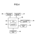
- FIG. 4 is a control block diagram of the injection molding machine according to the embodiment of the invention
- FIG. 5 is a time chart illustrating the operation of the injection molding machine according to the embodiment of the invention.
- reference numeral 81 denotes a controller
- the controller 81 includes a CPU 82 as an arithmetic device and a memory 83 as a recording unit and a storage unit.
- reference numeral 84 denotes a display unit
- reference numeral 85 denotes an operation unit
- reference numeral 86 denotes the metering motor
- reference numeral 87 denotes the injection motor
- reference numeral 88 denotes the mold clamping motor.
- the movable mold 12 is disposed at a mold opening position Q1 and the screw is disposed at a metering completion position R1. Moreover, at a timing t1, mold opening/closing processing means (mold opening/closing processing unit) (not shown) of the CPU 82 performs mold opening/closing processing, drives the mold clamping motor 88, starts closing the mold, and makes the movable mold 12 advance.
- a mold clamping force is gradually increased. Since it is known that a foreign material is not present between the stationary mold 11 and the movable mold 12 when the movable mold 12 reaches a mold protecting position (a position set to confirm whether a foreign material is present between the stationary mold 11 and the movable mold 12) at a timing t3, the mold opening/closing processing means increases a mold clamping force.
- the mold opening/closing processing means starts clamping the mold with a first mold clamping force F1.
- the first mold clamping force F1 is set so that the slide blocks 44 and 45 come into contact with each other at the mating faces with a small force and a gap between the slide blocks 44 and 45 and the cross-section of the flow passage of the gas vent 71 are large.
- the mold opening/closing processing means functions as flow passage cross-section setting processing means (a flow passage cross-section setting processing unit).
- an injection processing means (injection processing unit) (not shown) of the CPU 82 performs injection processing, starts making the screw, which is positioned at the metering completion position R1, advance, and starts filling the cavity space C with a resin.
- the processing means increases a mold clamping force and sets the mold clamping force to a second mold clamping force (set mold clamping force) F2.
- the mold opening/closing processing means can increase a mold clamping force at the timing t6 where a predetermined time ⁇ 1 has passed from the timing t4, and can set the mold clamping force to a second mold clamping force (set mold clamping force) F2.
- the second mold clamping force F2 is set so that the slide blocks 44 and 45 come into contact with each other at the mating faces with a large force and a gap between the slide blocks 44 and 45 (a gap between the parting lines PL) and the cross-section of the flow passage of the gas vent 71 are reduced.
- the mold opening/closing processing means functions as flow passage cross-section changing processing means (a flow passage cross-section changing processing unit).
- the hub portion 56 does not completely enter the hole of the locking ring 30, the hub portion 57 does not completely enter the concave portion of the locking ring 41, and the gap between the slide blocks 44 and 45 and the cross-section of the flow passage of the gas vent 71 are large. Accordingly, since it may be possible to make the amount of gas, which flows through the gas vent 71, large, it may be possible to prevent an oligomer from adhering to the inner peripheral surface of the gas vent 71 and to suppress the clogging of the gas vent 71.
Landscapes
- Engineering & Computer Science (AREA)
- Manufacturing & Machinery (AREA)
- Mechanical Engineering (AREA)
- Moulds For Moulding Plastics Or The Like (AREA)
- Injection Moulding Of Plastics Or The Like (AREA)
Abstract
Description
- This application is based upon and claims the benefit of priority from Japanese Patent Application No.
2010-136028, filed on June 15, 2010 - The present invention relates to an injection molding method and an injection molding machine.
- In the past, in a stretch blow molding method that forms a container made of a resin, for example, a PET resin, a container has been formed as a finished product, that is, a finished molded product formed by forming a preform (a parison with a bottom) in advance as a preliminarily molded product, that is, a preliminary molding by an injection molding machine, setting the preform in a stretch blow molding machine, mechanically stretching the preform in an axial direction while the preform is heated and softened, and stretching the preform in a radial direction by air blowing.
- Meanwhile, for example, in the case of a container that can be sealed by a screw type cap, a screw portion is formed at a spout of the container. However, the screw portion requires sufficiently high strength. For this reason, the screw portion is formed at the preform stage so as to have the same dimensions and shape as the screw portion of the container that is the finished product.
- In the injection molding machine that forms a preform, like in a general injection molding machine, a resin heated and melted in a heating cylinder is filled in a cavity space of a mold device and is cooled and solidified in the cavity space, so that a preform is formed.
- The injection molding machine includes the mold device, a mold clamping device, and injection device. The injection device includes the heating cylinder, an injection nozzle that is mounted on the front end of the heating cylinder and injects the melted resin, a screw that is disposed in the heating cylinder so as to be rotatable and able to freely advance and retreat, and the like. Further, the mold device includes a stationary mold and a movable mold. The movable mold is made to advance and retreat by the mold clamping device, so that the mold of the mold device is opened and closed, that is, mold closing, mold clamping, and mold opening. As the mold is clamped, a cavity space is formed between the stationary mold and the movable mold.
- Further, when the screw is rotated in a metering process, the melted resin is collected on the front of the screw. Accordingly, the screw retreats, and the mold of the mold device is closed and clamped while the screw retreats. Subsequently, the screw is made to advance in the injection process, so that the resin collected on the front side of the screw is injected from the injection nozzle and is filled in the cavity space through a runner such as a hot runner formed at the mold device. Next, the resin in the cavity space is cooled and solidified in a cooling process, so that a preform is formed. Subsequently, the mold is opened and the preform is taken out.
- Meanwhile, the resin is melted in the heating cylinder, and generates gas while being heated in the hot runner. Further, if the generated gas remains in the cavity space, sinks are formed on the surface of the preform or bubbles are formed in the preform. In particular, if sinks are formed on the surface of the screw portion of the preform or bubbles are formed in the screw portion, a sealing property between a cap and the screw portion of a finished container deteriorates. For this reason, it is not possible to seal the container by the cap.
- Accordingly, in the mold device in the related art, a gas vent is formed at the parting lines between the stationary mold and the movable mold by a groove having a small depth, so that gas in the cavity space is discharged to the outside of the mold device through the gas vent (for example, see Patent Literature 1).
-
- [PTL 1]
JP-A-7-285135 - According to an embodiment of the invention, there is provided an injection molding method of an injection molding machine including reducing a cross-section of a flow passage of a gas discharge portion formed at parting surfaces at a predetermined timing after a start of a filling of a molding material.
-
-
FIG. 1 is a view showing a split slide block of an embodiment of the invention. -
FIG. 2 is a sectional view of a mold device according to an embodiment of the invention. -
FIG. 3 is a cross-sectional view of main parts of the mold device according to an embodiment of the invention. -
FIG. 4 is a control block diagram of an injection molding machine according to an embodiment of the invention. -
FIG. 5 is a time chart illustrating the operation of the injection molding machine according to an embodiment of the invention. -
- in the mold device in the related art, an ingredient contained in the gas, for example, an oligomer (low-molecular resin) adheres to the inner peripheral surface of the gas vent as a foreign material when the gas passes through the gas vent. For this reason, the gas vent is clogged in a short time.
- Accordingly, since the mold device needs to be cleaned at regular intervals and adhering oligomer needs to be removed, not only the maintenance of the mold device is troublesome but also the productivity of a preform deteriorates.
- There is a need for providing an injection molding method that can suppress the clogging of a gas vent, simplify the maintenance of a mold device, and improve the productivity of a molded product.
- An injection molding method according to an embodiment of the invention is applied to an injection molding machine including a split mold where a gas discharge portion is formed at parting surfaces.
- Further, the cross-section of a flow passage of the gas discharge portion is reduced at a predetermined timing after the start of the filling of a molding material.
- According to an embodiment of the invention, the injection molding method is applied to an injection molding machine including a split mold where a gas discharge portion is formed at parting surfaces.
- Further, the cross-section of a flow passage of the gas discharge portion is reduced at a predetermined timing after the start of the filling of a molding material.
- In this case, since the cross-section of the flow passage of the gas discharge portion is reduced after a cavity space starts being filled with a molding material, it may be possible to make the amount of gas, which flows through the gas discharge portion, large while the cross-section of the flow passage is reduced after the start of the filling of a molding material. Accordingly, it may be possible to suppress the adhesion of a foreign material to the inner peripheral surface of the gas discharge portion and to suppress the clogging of the gas discharge portion.
- As a result, since the mold device does not need to be cleaned at regular intervals and adhering materials do not need to be removed, it may be possible not only to simplify the maintenance of the mold device but also to improve the productivity of a molded product.
- Embodiments of the invention will be described in detail below with reference to the drawings. In this case, an injection molding machine, which is used to form a preform as a preliminary molded product, will be described.
-
FIG. 1 is a view showing a split slide block of an embodiment of the invention,FIG. 2 is a sectional view of a mold device according to an embodiment of the invention, andFIG. 3 is a cross-sectional view of main parts of the mold device according to the embodiment of the invention. - In
FIGS. 1 to 3 ,reference numeral 11 denotes a stationary mold as a first mold, andreference numeral 12 denotes a movable mold as a second mold that is disposed so as to freely advance and retreat relative to thestationary mold 11. Thestationary mold 11 and themovable mold 12 form a mold device. - Further, the
stationary mold 11 is mounted on a stationary platen (not shown) and themovable mold 12 is mounted on a movable platen (not shown). As the movable platen is made to advance and retreat by a toggle mechanism (not shown) as a mold clamping force generating unit, themovable mold 12 is made to advance and retreat so that the mold of the mold device is closed, clamped, and opened. A cavity space C having a shape corresponding to the preform is formed by thestationary mold 11 and themovable mold 12 during the mold clamping. Meanwhile, reference character PL denotes parting lines that formmating faces between thestationary mold 11 and themovable mold 12, that is, parting surfaces. Furthermore, the stationary platen, the movable platen, and the toggle mechanism form a mold clamping device. The mold clamping device includes a mold clamping motor as a drive unit that clamps a mold, and can make the movable platen advance and retreat by operating the toggle mechanism through the drive of the mold clamping motor. Moreover, a mold clamping cylinder may be used instead of the toggle mechanism and the mold clamping motor. - Meanwhile, in the description of the invention, as seen from the
stationary mold 11, a direction approaching themovable mold 12 corresponds to the front side and a direction separated from themovable mold 12 corresponds to the rear side. Further, as seen from themovable mold 12, a direction approaching thestationary mold 11 corresponds to the front side and a direction separated from thestationary mold 11 corresponds to the rear side. - The
stationary mold 11 includes a manifold (not shown), aspacer plate 15, anozzle unit 16 that is supported by thespacer plate 15, amold plate 17 that is mounted on the front side of thespacer plate 15, abottom cavity 18 as a first cavity that is supported by themold plate 17 and is disposed by coming onto contact with the front end of thenozzle unit 16, acavity plate 21 that is mounted on the front side of themold plate 17, a side cavity (simply referred to as a "cavity") 22 as a second cavity that is supported by thecavity plate 21 and is disposed by coming onto contact with the front end of thebottom cavity 18, and anannular locking ring 30 as a first fastening member that is mounted on the front side of thecavity plate 21 and theside cavity 22, and the like. Meanwhile, for the purpose of the positioning and alignment of thelocking ring 30 relative to theside cavity 22, anannular projection 22a is formed at the front end of theside cavity 22 and theprojection 22a is fitted to a hole of thelocking ring 30. - The stationary platen is disposed on the rear side of the manifold, and an injection device (not shown) is disposed on the rear side of the stationary platen. The injection device includes a heating cylinder as a cylinder member, and a screw as an injection member that is disposed in the heating cylinder so as to be rotatable and freely advance and retreat. In order to rotate the screw or make the screw advance, the injection device further includes a metering motor as a metering drive unit, an injection motor as an injection drive unit, and the like. Furthermore, in a metering process, it may be possible to collect a resin as a molding material on the front side of the screw in the heating cylinder by rotating the screw through the drive of the metering motor. In an injection process, it may be possible to inject the collected resin from an injection nozzle, which is mounted on the front end of the heating cylinder, by making the screw advance through the drive of the injection motor, and to fill the cavity space C with the resin.
- Moreover, the
nozzle unit 16 includes anozzle 25, aneedle 27 as a valve element, aheater 28 as a heating element, and the like. Thenozzle 25 includes a columnar throughhole 23, and anozzle opening 24 is formed at the front end of the nozzle so as to communicate with the throughhole 23. Theneedle 27 as a valve element is disposed in the throughhole 23 so as to freely advance and retreat, opens thenozzle opening 24 when retreating, and closes thenozzle opening 24 when advancing. Theheater 28 as a heating element is disposed on the outer peripheral surface of the throughhole 23, and heats a resin so that the melted resin is maintained. Further, the resin passes through a hot runner (not shown) formed at the manifold, and is sent to the throughhole 23. - Further, the
bottom cavity 18 includes a concave surface s1 that is formed at the front end of the bottom cavity so as to have a shape corresponding to the bottom of a preform, and agate 31 that communicates with thenozzle opening 24 of thenozzle unit 16 and is opened to the concave surface s1. Thegate 31 functions as a supply port through which the resin sent from the throughhole 23 is supplied to the cavity space C. - Furthermore, the
side cavity 22 has a tubular shape and includes a concave surface s2 that has a shape corresponding to the side portion of the preform. - Moreover, the
movable mold 12 includes acore seat 34, acylindrical core 37, anannular locking ring 41 as a second fastening member, asplit 43 as a split mold, and the like. Thecylindrical core 37 is supported by thecore seat 34, and includes abase portion 35 having a large diameter and atubular core mold 36. Thetubular core mold 36 is formed to protrude forward from thebase portion 35 and toward the inside of thebottom cavity 18 and theside cavity 22. Theannular locking ring 41 as a second fastening member is mounted on the core 37 at a predetermined position, that is, on the front side of thebase portion 35 in this embodiment, and is disposed so as to surround thecore mold 36. Thesplit 43 as a split mold is disposed so as to surround thecore mold 36 and be movable to the front side of the lockingring 41. - A
columnar hole 51 is formed in thecore 37. Atubular pipe 52 extends in thehole 51 with a predetermined distance between the inner peripheral surface of thehole 51 and itself so that the front end of the cylindrical pipe faces the front end of thecore mold 36. Further, water as a cooling medium is supplied into thepipe 52 from a cooling source (not shown). The water passes through a first flow passage formed in thepipe 52, is reversed at the front end of thepipe 52, and passes through a second flow passage that is formed between the inner peripheral surface of thehole 51 and the outer peripheral surface of thepipe 52. While passing through the second flow passage, the water cools thecore 37. Then, the water returns to the cooling source. - Further, the
split 43 includes slide blocks 44 and 45 as a plurality of (two in this embodiment) mold members that is disposed at a position corresponding to a screw portion of the preform and divided at predetermined positions in a circumferential direction. Each of the slide blocks 44 and 45 has a half-divided structure. A cam (not shown) is operated while interlocking with the opening/closing of the mold of the mold device. With the operation of the cam, the slide blocks 44 and 45 are moved in a radial direction (the directions of arrows A and B ofFIG. 2 ). Each of the slide blocks 44 and 45 includes aflange portion 55 that is formed at the middle portion of the slide block in an axial direction, ahub portion 56 that is formed to protrude forward from theflange portion 55 and has a diameter smaller than the diameter of theflange portion 55, and ahub portion 57 that is formed to protrude rearward from theflange portion 55 and has a diameter smaller than the diameter of theflange portion 55. - The
hub portion 56 includes a tapered surface sa that is formed so that an outer diameter is reduced toward the front side. Thehub portion 57 includes a tapered surface sb that is formed so that an outer diameter is reduced toward the rear side. - Furthermore, a through
hole 61, which forms a screw portion of a preform and a neck portion adjacent to the screw portion, is formed at theslide block 44; asmooth column surface 62 is formed at the front half portion of the through hole 61 (a portion of the through hole corresponding to the side cavity 22); and ascrew groove 63, which forms a screw portion of the preform, is formed at the rear half portion of the through hole 61 (a portion of the through hole corresponding to the locking ring 41). - Meanwhile, when the mold is opened so that the
movable mold 12 is separated from thestationary mold 11, the slide blocks 44 and 45 are disposed at retreat positions that are positioned at the outer side in the radial direction. When the mold is closed so that themovable mold 12 comes into contact with thestationary mold 11, the slide blocks 44 and 45 are disposed at operation positions that are positioned at the inner side in the radial direction. Accordingly, the slide blocks 44 and 45 form the cavity space C together with thebottom cavity 18, theside cavity 22, the lockingring 41, and the like. - Further, a hole having a shape corresponding to the
hub portion 56 is formed at the front end portion of the lockingring 30, and a tapered surface sc corresponding to the tapered surface sa is formed on the inner peripheral surface of the hole so that the inner diameter of the tapered surface sc is increased toward the front side. Furthermore, a concave portion having a shape corresponding to thehub portion 57 is formed at the front end portion of the lockingring 41, and a tapered surface sd corresponding to the tapered surface sb is formed on the inner peripheral surface of the concave portion so that the inner diameter of the concave portion is increased toward the front side. - In the mold device having the above-mentioned structure, when the mold clamping device makes the
movable mold 12 advance by making the movable platen advance so as to close the mold, the slide blocks 44 and 45 disposed at retreat positions are moved inward in the radial direction with the operation of the cam, are disposed at the operation positions, and come into contact with each other. Subsequently, the split 43 (the slide blocks 44 and 45) and theside cavity 22 come into contact with each other. Accordingly, a cavity space C is formed between thestationary mold 11 and themovable mold 12, that is, between the core 37 and thebottom cavity 18 of themovable mold 12 and theside cavity 22 of thestationary mold 11. - Subsequently, when the mold clamping device generates a mold clamping force and clamps the mold, the
movable mold 12 is pressed against thestationary mold 11 by the mold clamping force. Accordingly, a resin injected by the injection device is filled in the cavity space C through the hot runner, the throughhole 23, and thegate 31. - In this case, the
hub portion 56 enters the hole of the lockingring 30 through the sliding between the tapered surface sa and the tapered surface sc, and thehub portion 57 enters the concave portion of the lockingring 41 through the sliding between the tapered surface sb and the tapered surface sd. Accordingly, the slide blocks 44 and 45 come into close contact with each other at mating faces. Therefore, the resin, which is filed in the cavity space C, does not leak from a gap between the slide blocks 44 and 45. - Further, when the resin filled in the cavity space C is cooled and solidified, the mold clamping device makes the movable platen retreat and opens the mold. Accordingly, the slide blocks 44 and 45 are moved outward in the radial direction with the operation of the cam, and are disposed at the retreat positions.
- Meanwhile, as the cavity space C is filled with the resin, air in the cavity space C needs to be discharged to the outside of the mold device. Further, the resin is melted in the heating cylinder, and generates gas while being heated in the hot runner. Furthermore, if air and the generated gas remain in the cavity space C after the cavity space C is filled with the resin, sinks are formed on the surface of the preform or bubbles are formed in the preform. In particular, if sinks are formed on the surface of the screw portion of the preform or bubbles are formed in the screw portion, a sealing property between a cap and the screw portion of a container as a finished product deteriorates. For this reason, it is not possible to seal the container by the cap.
- Accordingly, in this embodiment, a
gas vent 71 as a gas discharge portion is formed between the slide blocks 44 and 45 of thesplit 43 and air and gas in the cavity space C are discharged to the outside of the mold device through thegas vent 71. - For this reason, concave portions AR1 and AR2, which have a predetermined shape, that is, a rectangular shape in this embodiment, having a small depth from edges eg1 and eg2 of the inner peripheral surface to the outside in the radial direction, are formed at a predetermined position, that is, near the inner peripheral surface of the through
hole 61 in this embodiment, on one of the respective mating faces of the slide blocks 44 and 45, that is, a mating face Sm of theslide block 44 in this embodiment. Further,first grooves 73, which are deeper than the concave portions AR1 and AR2, are formed from the respective concave portions AR1 and AR2 to the outside in the radial direction, andsecond grooves 74, which are deeper than the concave portions AR1 and AR2, are formed from the respective concave portions AR1 and AR2 toward the front end of theslide block 44. - Accordingly, when the slide blocks 44 and 45 come into contact with each other at the mating faces, a first
gas vent passage 75 is formed by the concave portions AR1 and AR2, a secondgas vent passage 76 is formed by thefirst groove 73, and a third gas vent passage (not shown) is formed by thesecond groove 74. Therefore, as the cavity space C is filled with the resin, it may be possible to discharge air and gas in the cavity space C to the outside of the mold device through the firstgas vent passage 75, the secondgas vent passage 76, and the third gas vent passage. - As a result, it may be possible to prevent sinks from being formed on the surface of a preform or to prevent bubbles from being formed in a preform. In particular, since it may be possible to prevent sinks from being formed on the surface of a preform or to prevent bubbles from being formed in a preform, it may be possible to improve a sealing property between a cap and the screw portion of the container and to sufficiently seal the container by a cap.
- Meanwhile, if an ingredient contained in the gas, for example, an oligomer adheres to the inner peripheral surface of the
gas vent 71, thegas vent 71 is clogged in a short time. Accordingly, making thegas vent 71 large can be considered. However, if thegas vent 71 is large, the resin leaks to the parting surfaces from thegas vent 71, that is, flash are formed when the cavity space is completely filled with the resin. - Accordingly, in this embodiment, the slide blocks 44 and 45 come into contact with each other at the mating faces with a small force for a predetermined time after the start of the closing of the mold of the mold device, and a gap between the slide blocks 44 and 45 and the cross-section of the flow passage of the
gas vent 71 are large. -
FIG. 4 is a control block diagram of the injection molding machine according to the embodiment of the invention, andFIG. 5 is a time chart illustrating the operation of the injection molding machine according to the embodiment of the invention. - In
FIG. 4 ,reference numeral 81 denotes a controller, and thecontroller 81 includes aCPU 82 as an arithmetic device and amemory 83 as a recording unit and a storage unit. Further,reference numeral 84 denotes a display unit,reference numeral 85 denotes an operation unit,reference numeral 86 denotes the metering motor,reference numeral 87 denotes the injection motor, andreference numeral 88 denotes the mold clamping motor. - In the injection molding machine having the above-mentioned structure, first, the
movable mold 12 is disposed at a mold opening position Q1 and the screw is disposed at a metering completion position R1. Moreover, at a timing t1, mold opening/closing processing means (mold opening/closing processing unit) (not shown) of theCPU 82 performs mold opening/closing processing, drives themold clamping motor 88, starts closing the mold, and makes themovable mold 12 advance. - After that, when the
movable mold 12 comes into contact with thestationary mold 11 at a timing t2, a mold clamping force is gradually increased. Since it is known that a foreign material is not present between thestationary mold 11 and themovable mold 12 when themovable mold 12 reaches a mold protecting position (a position set to confirm whether a foreign material is present between thestationary mold 11 and the movable mold 12) at a timing t3, the mold opening/closing processing means increases a mold clamping force. - Subsequently, at a timing t4, the mold opening/closing processing means starts clamping the mold with a first mold clamping force F1.
- In this case, the first mold clamping force F1 is set so that the slide blocks 44 and 45 come into contact with each other at the mating faces with a small force and a gap between the slide blocks 44 and 45 and the cross-section of the flow passage of the
gas vent 71 are large. Meanwhile, in this case, the mold opening/closing processing means functions as flow passage cross-section setting processing means (a flow passage cross-section setting processing unit). - Further, at a predetermined timing t5 after the timing t4, an injection processing means (injection processing unit) (not shown) of the
CPU 82 performs injection processing, starts making the screw, which is positioned at the metering completion position R1, advance, and starts filling the cavity space C with a resin. - Furthermore, when the screw reaches a pressure-rise screw position R2, which is positioned on the front side of an advance limit position R3, at a timing t6, the processing means increases a mold clamping force and sets the mold clamping force to a second mold clamping force (set mold clamping force) F2.
- Meanwhile, the mold opening/closing processing means can increase a mold clamping force at the timing t6 where a predetermined time τ1 has passed from the timing t4, and can set the mold clamping force to a second mold clamping force (set mold clamping force) F2.
- In this case, until the screw reaches a pressure-rise screw position R2, the
movable mold 12 retreats due to the pressure of a resin. However, since the resin filled in the cavity space C does not reach thegas vent 71, the resin does not leak to the outside of the mold device through thegas vent 71. - In this case, the second mold clamping force F2 is set so that the slide blocks 44 and 45 come into contact with each other at the mating faces with a large force and a gap between the slide blocks 44 and 45 (a gap between the parting lines PL) and the cross-section of the flow passage of the
gas vent 71 are reduced. Meanwhile, in this case, the mold opening/closing processing means functions as flow passage cross-section changing processing means (a flow passage cross-section changing processing unit). - After that, the screw reaches the advance limit position R3 at a timing t7.
- Since the first mold clamping force F1 is generated between the timing t4 and the timing t6 in this embodiment as described above, the
hub portion 56 does not completely enter the hole of the lockingring 30, thehub portion 57 does not completely enter the concave portion of the lockingring 41, and the gap between the slide blocks 44 and 45 and the cross-section of the flow passage of thegas vent 71 are large. Accordingly, since it may be possible to make the amount of gas, which flows through thegas vent 71, large, it may be possible to prevent an oligomer from adhering to the inner peripheral surface of thegas vent 71 and to suppress the clogging of thegas vent 71. - As a result, since cleaning does not need to be frequently performed for the removal of the adhering oligomer, it may be possible not only to simplify the maintenance of the mold device but also to improve the preform productivity.
- Meanwhile, the invention is not limited to the above-mentioned embodiment, and may have various modifications on the basis of the concept of the invention. These modifications are not excluded from the scope of the invention.
Claims (6)
- An injection molding method of an injection molding machine comprising:reducing a cross-section of a flow passage of a gas discharge portion formed at parting surfaces at a predetermined timing after a start of a filling of a molding material.
- The injection molding method according to claim 1, wherein the cross-section of the flow passage is reduced by increasing a mold clamping force at the predetermined timing.
- The injection molding method according to claim 2, wherein the cross-section of the flow passage is reduced by reducing a gap between a parting surfaces of a split mold through the increase of the mold clamping force.
- An injection molding machine comprising:a split mold where a gas discharge portion is formed at parting surfaces,a controller that controls the operation of the split mold,
wherein the controller includes a flow passage cross-section changing processing unit that reduces the cross-section of a flow passage of the gas discharge portion at a predetermined timing after the start of the filling of a - The injection molding machine according to claim 4,
wherein the flow passage cross-section changing processing unit reduces the cross-section of the flow passage by increasing a mold clamping force at the predetermined timing. - The injection molding machine according to claim 5,
wherein the flow passage cross-section changing processing unit reduces the cross-section of the flow passage by reducing a gap between the parting surfaces of the split mold through the increase of the mold clamping force.
Applications Claiming Priority (1)
| Application Number | Priority Date | Filing Date | Title |
|---|---|---|---|
| JP2010136028A JP5684498B2 (en) | 2010-06-15 | 2010-06-15 | Injection molding method and injection molding machine |
Publications (2)
| Publication Number | Publication Date |
|---|---|
| EP2397302A1 true EP2397302A1 (en) | 2011-12-21 |
| EP2397302B1 EP2397302B1 (en) | 2015-02-18 |
Family
ID=44512247
Family Applications (1)
| Application Number | Title | Priority Date | Filing Date |
|---|---|---|---|
| EP11004895.6A Active EP2397302B1 (en) | 2010-06-15 | 2011-06-15 | Injection molding method and injection molding machine |
Country Status (5)
| Country | Link |
|---|---|
| US (1) | US8709326B2 (en) |
| EP (1) | EP2397302B1 (en) |
| JP (1) | JP5684498B2 (en) |
| CN (1) | CN102328404B (en) |
| CA (1) | CA2742230C (en) |
Cited By (1)
| Publication number | Priority date | Publication date | Assignee | Title |
|---|---|---|---|---|
| CN111387763A (en) * | 2020-03-20 | 2020-07-10 | 谷小龙 | Display method for highlighting stage creation |
Families Citing this family (10)
| Publication number | Priority date | Publication date | Assignee | Title |
|---|---|---|---|---|
| EP2813342A1 (en) | 2009-11-30 | 2014-12-17 | Husky Injection Molding Systems S.A. | Molding apparatus |
| CA2933802C (en) | 2011-08-04 | 2017-10-03 | Husky Injection Molding Systems Ltd. | A mold component having a residue cleaning feature |
| KR101423130B1 (en) * | 2012-06-22 | 2014-07-31 | 주식회사 엠피에이테크놀로지 | Apparatus of vacuum injection molding |
| JP6303003B2 (en) * | 2014-06-04 | 2018-03-28 | オリンパス株式会社 | Injection molding method for resin molded products and identification method of clamping force |
| EP3271131B1 (en) | 2015-03-20 | 2020-12-30 | Husky Injection Molding Systems Ltd. | Molding system having a mold stack with a cleaning configuration and a shut height adjustment mechanism |
| JP6576862B2 (en) * | 2016-03-16 | 2019-09-18 | 東芝メモリ株式会社 | Transfer molding equipment |
| JP6795348B2 (en) * | 2016-07-29 | 2020-12-02 | 東洋製罐株式会社 | Molding method and molding equipment for molten material |
| CN108215069B (en) | 2016-12-14 | 2020-10-23 | 赫斯基注塑系统有限公司 | Split mold insert and mold stack |
| KR102205197B1 (en) * | 2020-02-21 | 2021-01-19 | 강태윤 | An apparatus for injection blow molding |
| KR20230122440A (en) * | 2022-02-14 | 2023-08-22 | 효성중공업 주식회사 | High-speed molding device |
Citations (6)
| Publication number | Priority date | Publication date | Assignee | Title |
|---|---|---|---|---|
| JPH03199023A (en) * | 1989-12-28 | 1991-08-30 | Toyo Seikan Kaisha Ltd | Injection molding mold and maintenance thereof |
| US5500166A (en) * | 1992-01-29 | 1996-03-19 | Kabushiki Kaisha Komatsu Seisakusho | Method for controlling injection volume of material into mold |
| JP2001047483A (en) * | 1999-08-06 | 2001-02-20 | Nok Corp | Injection molding machine |
| US20040081717A1 (en) * | 2002-10-24 | 2004-04-29 | Marazita Jose R. | Injection molding machine and controller |
| CN201325148Y (en) * | 2008-11-14 | 2009-10-14 | 解冬正 | Bottle billet die |
| JP2010136028A (en) | 2008-12-03 | 2010-06-17 | Ntt Docomo Inc | Device and method for generating signal |
Family Cites Families (12)
| Publication number | Priority date | Publication date | Assignee | Title |
|---|---|---|---|---|
| US4828769A (en) * | 1986-05-05 | 1989-05-09 | Galic/Maus Ventures | Method for injection molding articles |
| US5061168A (en) * | 1990-07-09 | 1991-10-29 | Fox Alton L | Modular unscrewing mold apparatus |
| JPH06126740A (en) * | 1992-10-20 | 1994-05-10 | Mitsubishi Plastics Ind Ltd | Injection molding method of parison for synthetic resin bottles |
| JPH07256722A (en) * | 1994-03-24 | 1995-10-09 | Fanuc Ltd | Injection molding control method in injection molding machine |
| JP3519511B2 (en) * | 1995-07-27 | 2004-04-19 | ファナック株式会社 | Control method and apparatus for injection molding machine |
| JPH1034692A (en) * | 1996-07-29 | 1998-02-10 | Mitsuboshi Belting Ltd | Molding method for thermosetting resin molded product |
| JP2002166448A (en) * | 2000-12-01 | 2002-06-11 | Sony Corp | Molding apparatus for molding and molding method |
| US20060198974A1 (en) * | 2003-01-24 | 2006-09-07 | Miller William E | Apparatus and method for removing a molded article from a mold, and a molded article |
| US7481642B2 (en) * | 2004-04-23 | 2009-01-27 | Husky Injection Molding Systems Ltd. | Method and apparatus for controlling a vent gap with active material elements |
| US7580771B2 (en) * | 2004-10-19 | 2009-08-25 | Husky Injection Molding Systems Ltd. | Intelligent molding environment and method of configuring a molding system |
| GB2430642A (en) * | 2005-10-03 | 2007-04-04 | Im Pak Technologies Ltd | Injection impact compression moulding |
| US8398392B2 (en) * | 2011-01-13 | 2013-03-19 | Husky Injection Molding Systems Ltd. | Neck ring for forming a neck portion of a preform and the mold stack incorporating same |
-
2010
- 2010-06-15 JP JP2010136028A patent/JP5684498B2/en active Active
-
2011
- 2011-06-02 CA CA2742230A patent/CA2742230C/en not_active Expired - Fee Related
- 2011-06-13 US US13/158,847 patent/US8709326B2/en active Active
- 2011-06-15 CN CN201110161078.8A patent/CN102328404B/en active Active
- 2011-06-15 EP EP11004895.6A patent/EP2397302B1/en active Active
Patent Citations (6)
| Publication number | Priority date | Publication date | Assignee | Title |
|---|---|---|---|---|
| JPH03199023A (en) * | 1989-12-28 | 1991-08-30 | Toyo Seikan Kaisha Ltd | Injection molding mold and maintenance thereof |
| US5500166A (en) * | 1992-01-29 | 1996-03-19 | Kabushiki Kaisha Komatsu Seisakusho | Method for controlling injection volume of material into mold |
| JP2001047483A (en) * | 1999-08-06 | 2001-02-20 | Nok Corp | Injection molding machine |
| US20040081717A1 (en) * | 2002-10-24 | 2004-04-29 | Marazita Jose R. | Injection molding machine and controller |
| CN201325148Y (en) * | 2008-11-14 | 2009-10-14 | 解冬正 | Bottle billet die |
| JP2010136028A (en) | 2008-12-03 | 2010-06-17 | Ntt Docomo Inc | Device and method for generating signal |
Cited By (1)
| Publication number | Priority date | Publication date | Assignee | Title |
|---|---|---|---|---|
| CN111387763A (en) * | 2020-03-20 | 2020-07-10 | 谷小龙 | Display method for highlighting stage creation |
Also Published As
| Publication number | Publication date |
|---|---|
| JP2012000803A (en) | 2012-01-05 |
| JP5684498B2 (en) | 2015-03-11 |
| US20110304077A1 (en) | 2011-12-15 |
| CN102328404B (en) | 2016-01-20 |
| CA2742230A1 (en) | 2011-12-15 |
| CA2742230C (en) | 2015-08-11 |
| CN102328404A (en) | 2012-01-25 |
| EP2397302B1 (en) | 2015-02-18 |
| US8709326B2 (en) | 2014-04-29 |
Similar Documents
| Publication | Publication Date | Title |
|---|---|---|
| CA2742230C (en) | Injection molding method and injection molding machine | |
| KR101205686B1 (en) | A mold stack for a preform | |
| CN101678587B (en) | Mold inserts and mold stacks for use with molding machines | |
| CN208615198U (en) | Mold stack, injection mold and molding-system for moulding preforms | |
| JP5723018B2 (en) | Mold stack for preforms | |
| JPH11115001A (en) | Valve gate assembly and injection molding method | |
| CN105050790B (en) | Die stacks with floating cavity inserts | |
| KR100966877B1 (en) | Hot runner system and injection molding method using the same | |
| CN104822506A (en) | Method of manufacturing injected and blown product | |
| JP6795348B2 (en) | Molding method and molding equipment for molten material | |
| US9061457B2 (en) | Stripper sleeve | |
| US20050200048A1 (en) | Apparatus for valve-gate injection molding and method for the same | |
| US7063525B2 (en) | Extrusion die | |
| US7458806B2 (en) | Waste-less injection molding fan gate | |
| EP4129617B1 (en) | Mold for molding an article in two materials | |
| CN113442394A (en) | Method for producing orthodontic film, computer readable medium, mold and injection molding machine | |
| US20250262808A1 (en) | Injection mold component | |
| US7479244B2 (en) | Process for the production of plates made of transparent plastic material with non-transparent areas | |
| JP6615040B2 (en) | Cylinder molding die and cylinder molding method using the same | |
| WO2007080797A1 (en) | Plasticizing apparatus and method for controlling same | |
| US20060222730A1 (en) | Hot edge diaphragm gate for injection mold | |
| US7291007B2 (en) | Valve ring gate for thermoplastic and thermoset injection molding | |
| CN207696949U (en) | New diverter plate valve pin plug | |
| JPH04270615A (en) | Manufacture of hollow body | |
| KR20180000355U (en) | Nozzle device of an injection molding machine |
Legal Events
| Date | Code | Title | Description |
|---|---|---|---|
| 17P | Request for examination filed |
Effective date: 20110615 |
|
| AK | Designated contracting states |
Kind code of ref document: A1 Designated state(s): AL AT BE BG CH CY CZ DE DK EE ES FI FR GB GR HR HU IE IS IT LI LT LU LV MC MK MT NL NO PL PT RO RS SE SI SK SM TR |
|
| AX | Request for extension of the european patent |
Extension state: BA ME |
|
| PUAI | Public reference made under article 153(3) epc to a published international application that has entered the european phase |
Free format text: ORIGINAL CODE: 0009012 |
|
| 17Q | First examination report despatched |
Effective date: 20130207 |
|
| RIC1 | Information provided on ipc code assigned before grant |
Ipc: B29C 45/56 20060101ALN20140715BHEP Ipc: B29C 45/76 20060101ALN20140715BHEP Ipc: B29C 45/34 20060101AFI20140715BHEP |
|
| GRAP | Despatch of communication of intention to grant a patent |
Free format text: ORIGINAL CODE: EPIDOSNIGR1 |
|
| RIC1 | Information provided on ipc code assigned before grant |
Ipc: B29C 45/34 20060101AFI20140718BHEP Ipc: B29C 45/56 20060101ALN20140718BHEP Ipc: B29C 45/76 20060101ALN20140718BHEP |
|
| INTG | Intention to grant announced |
Effective date: 20140827 |
|
| RIC1 | Information provided on ipc code assigned before grant |
Ipc: B29C 45/34 20060101AFI20140818BHEP Ipc: B29C 45/76 20060101ALN20140818BHEP Ipc: B29C 45/56 20060101ALN20140818BHEP |
|
| GRAS | Grant fee paid |
Free format text: ORIGINAL CODE: EPIDOSNIGR3 |
|
| GRAA | (expected) grant |
Free format text: ORIGINAL CODE: 0009210 |
|
| AK | Designated contracting states |
Kind code of ref document: B1 Designated state(s): AL AT BE BG CH CY CZ DE DK EE ES FI FR GB GR HR HU IE IS IT LI LT LU LV MC MK MT NL NO PL PT RO RS SE SI SK SM TR |
|
| REG | Reference to a national code |
Ref country code: GB Ref legal event code: FG4D |
|
| REG | Reference to a national code |
Ref country code: CH Ref legal event code: EP Ref country code: CH Ref legal event code: NV Representative=s name: RIEDERER HASLER AND PARTNER PATENTANWAELTE AG, LI |
|
| REG | Reference to a national code |
Ref country code: AT Ref legal event code: REF Ref document number: 710471 Country of ref document: AT Kind code of ref document: T Effective date: 20150315 |
|
| REG | Reference to a national code |
Ref country code: IE Ref legal event code: FG4D |
|
| REG | Reference to a national code |
Ref country code: DE Ref legal event code: R096 Ref document number: 602011013716 Country of ref document: DE Effective date: 20150402 |
|
| REG | Reference to a national code |
Ref country code: NL Ref legal event code: VDEP Effective date: 20150218 |
|
| REG | Reference to a national code |
Ref country code: LT Ref legal event code: MG4D |
|
| PG25 | Lapsed in a contracting state [announced via postgrant information from national office to epo] |
Ref country code: FI Free format text: LAPSE BECAUSE OF FAILURE TO SUBMIT A TRANSLATION OF THE DESCRIPTION OR TO PAY THE FEE WITHIN THE PRESCRIBED TIME-LIMIT Effective date: 20150218 Ref country code: NO Free format text: LAPSE BECAUSE OF FAILURE TO SUBMIT A TRANSLATION OF THE DESCRIPTION OR TO PAY THE FEE WITHIN THE PRESCRIBED TIME-LIMIT Effective date: 20150518 Ref country code: LT Free format text: LAPSE BECAUSE OF FAILURE TO SUBMIT A TRANSLATION OF THE DESCRIPTION OR TO PAY THE FEE WITHIN THE PRESCRIBED TIME-LIMIT Effective date: 20150218 Ref country code: SE Free format text: LAPSE BECAUSE OF FAILURE TO SUBMIT A TRANSLATION OF THE DESCRIPTION OR TO PAY THE FEE WITHIN THE PRESCRIBED TIME-LIMIT Effective date: 20150218 Ref country code: ES Free format text: LAPSE BECAUSE OF FAILURE TO SUBMIT A TRANSLATION OF THE DESCRIPTION OR TO PAY THE FEE WITHIN THE PRESCRIBED TIME-LIMIT Effective date: 20150218 Ref country code: HR Free format text: LAPSE BECAUSE OF FAILURE TO SUBMIT A TRANSLATION OF THE DESCRIPTION OR TO PAY THE FEE WITHIN THE PRESCRIBED TIME-LIMIT Effective date: 20150218 |
|
| PG25 | Lapsed in a contracting state [announced via postgrant information from national office to epo] |
Ref country code: LV Free format text: LAPSE BECAUSE OF FAILURE TO SUBMIT A TRANSLATION OF THE DESCRIPTION OR TO PAY THE FEE WITHIN THE PRESCRIBED TIME-LIMIT Effective date: 20150218 Ref country code: IS Free format text: LAPSE BECAUSE OF FAILURE TO SUBMIT A TRANSLATION OF THE DESCRIPTION OR TO PAY THE FEE WITHIN THE PRESCRIBED TIME-LIMIT Effective date: 20150618 Ref country code: NL Free format text: LAPSE BECAUSE OF FAILURE TO SUBMIT A TRANSLATION OF THE DESCRIPTION OR TO PAY THE FEE WITHIN THE PRESCRIBED TIME-LIMIT Effective date: 20150218 Ref country code: GR Free format text: LAPSE BECAUSE OF FAILURE TO SUBMIT A TRANSLATION OF THE DESCRIPTION OR TO PAY THE FEE WITHIN THE PRESCRIBED TIME-LIMIT Effective date: 20150519 Ref country code: RS Free format text: LAPSE BECAUSE OF FAILURE TO SUBMIT A TRANSLATION OF THE DESCRIPTION OR TO PAY THE FEE WITHIN THE PRESCRIBED TIME-LIMIT Effective date: 20150218 |
|
| PG25 | Lapsed in a contracting state [announced via postgrant information from national office to epo] |
Ref country code: SK Free format text: LAPSE BECAUSE OF FAILURE TO SUBMIT A TRANSLATION OF THE DESCRIPTION OR TO PAY THE FEE WITHIN THE PRESCRIBED TIME-LIMIT Effective date: 20150218 Ref country code: DK Free format text: LAPSE BECAUSE OF FAILURE TO SUBMIT A TRANSLATION OF THE DESCRIPTION OR TO PAY THE FEE WITHIN THE PRESCRIBED TIME-LIMIT Effective date: 20150218 Ref country code: CZ Free format text: LAPSE BECAUSE OF FAILURE TO SUBMIT A TRANSLATION OF THE DESCRIPTION OR TO PAY THE FEE WITHIN THE PRESCRIBED TIME-LIMIT Effective date: 20150218 Ref country code: RO Free format text: LAPSE BECAUSE OF FAILURE TO SUBMIT A TRANSLATION OF THE DESCRIPTION OR TO PAY THE FEE WITHIN THE PRESCRIBED TIME-LIMIT Effective date: 20150218 Ref country code: EE Free format text: LAPSE BECAUSE OF FAILURE TO SUBMIT A TRANSLATION OF THE DESCRIPTION OR TO PAY THE FEE WITHIN THE PRESCRIBED TIME-LIMIT Effective date: 20150218 |
|
| REG | Reference to a national code |
Ref country code: DE Ref legal event code: R097 Ref document number: 602011013716 Country of ref document: DE |
|
| PG25 | Lapsed in a contracting state [announced via postgrant information from national office to epo] |
Ref country code: PL Free format text: LAPSE BECAUSE OF FAILURE TO SUBMIT A TRANSLATION OF THE DESCRIPTION OR TO PAY THE FEE WITHIN THE PRESCRIBED TIME-LIMIT Effective date: 20150218 |
|
| PLBE | No opposition filed within time limit |
Free format text: ORIGINAL CODE: 0009261 |
|
| STAA | Information on the status of an ep patent application or granted ep patent |
Free format text: STATUS: NO OPPOSITION FILED WITHIN TIME LIMIT |
|
| PG25 | Lapsed in a contracting state [announced via postgrant information from national office to epo] |
Ref country code: IT Free format text: LAPSE BECAUSE OF FAILURE TO SUBMIT A TRANSLATION OF THE DESCRIPTION OR TO PAY THE FEE WITHIN THE PRESCRIBED TIME-LIMIT Effective date: 20150218 |
|
| 26N | No opposition filed |
Effective date: 20151119 |
|
| PG25 | Lapsed in a contracting state [announced via postgrant information from national office to epo] |
Ref country code: MC Free format text: LAPSE BECAUSE OF FAILURE TO SUBMIT A TRANSLATION OF THE DESCRIPTION OR TO PAY THE FEE WITHIN THE PRESCRIBED TIME-LIMIT Effective date: 20150218 |
|
| REG | Reference to a national code |
Ref country code: AT Ref legal event code: UEP Ref document number: 710471 Country of ref document: AT Kind code of ref document: T Effective date: 20150218 |
|
| GBPC | Gb: european patent ceased through non-payment of renewal fee |
Effective date: 20150615 |
|
| PG25 | Lapsed in a contracting state [announced via postgrant information from national office to epo] |
Ref country code: LU Free format text: LAPSE BECAUSE OF FAILURE TO SUBMIT A TRANSLATION OF THE DESCRIPTION OR TO PAY THE FEE WITHIN THE PRESCRIBED TIME-LIMIT Effective date: 20150615 Ref country code: SI Free format text: LAPSE BECAUSE OF FAILURE TO SUBMIT A TRANSLATION OF THE DESCRIPTION OR TO PAY THE FEE WITHIN THE PRESCRIBED TIME-LIMIT Effective date: 20150218 |
|
| REG | Reference to a national code |
Ref country code: IE Ref legal event code: MM4A |
|
| REG | Reference to a national code |
Ref country code: FR Ref legal event code: ST Effective date: 20160229 |
|
| PG25 | Lapsed in a contracting state [announced via postgrant information from national office to epo] |
Ref country code: IE Free format text: LAPSE BECAUSE OF NON-PAYMENT OF DUE FEES Effective date: 20150615 Ref country code: GB Free format text: LAPSE BECAUSE OF NON-PAYMENT OF DUE FEES Effective date: 20150615 |
|
| PG25 | Lapsed in a contracting state [announced via postgrant information from national office to epo] |
Ref country code: BE Free format text: LAPSE BECAUSE OF FAILURE TO SUBMIT A TRANSLATION OF THE DESCRIPTION OR TO PAY THE FEE WITHIN THE PRESCRIBED TIME-LIMIT Effective date: 20150218 Ref country code: FR Free format text: LAPSE BECAUSE OF NON-PAYMENT OF DUE FEES Effective date: 20150630 |
|
| PG25 | Lapsed in a contracting state [announced via postgrant information from national office to epo] |
Ref country code: MT Free format text: LAPSE BECAUSE OF FAILURE TO SUBMIT A TRANSLATION OF THE DESCRIPTION OR TO PAY THE FEE WITHIN THE PRESCRIBED TIME-LIMIT Effective date: 20150218 |
|
| PG25 | Lapsed in a contracting state [announced via postgrant information from national office to epo] |
Ref country code: BG Free format text: LAPSE BECAUSE OF FAILURE TO SUBMIT A TRANSLATION OF THE DESCRIPTION OR TO PAY THE FEE WITHIN THE PRESCRIBED TIME-LIMIT Effective date: 20150218 Ref country code: HU Free format text: LAPSE BECAUSE OF FAILURE TO SUBMIT A TRANSLATION OF THE DESCRIPTION OR TO PAY THE FEE WITHIN THE PRESCRIBED TIME-LIMIT; INVALID AB INITIO Effective date: 20110615 Ref country code: SM Free format text: LAPSE BECAUSE OF FAILURE TO SUBMIT A TRANSLATION OF THE DESCRIPTION OR TO PAY THE FEE WITHIN THE PRESCRIBED TIME-LIMIT Effective date: 20150218 |
|
| PG25 | Lapsed in a contracting state [announced via postgrant information from national office to epo] |
Ref country code: CY Free format text: LAPSE BECAUSE OF FAILURE TO SUBMIT A TRANSLATION OF THE DESCRIPTION OR TO PAY THE FEE WITHIN THE PRESCRIBED TIME-LIMIT Effective date: 20150218 |
|
| PG25 | Lapsed in a contracting state [announced via postgrant information from national office to epo] |
Ref country code: TR Free format text: LAPSE BECAUSE OF FAILURE TO SUBMIT A TRANSLATION OF THE DESCRIPTION OR TO PAY THE FEE WITHIN THE PRESCRIBED TIME-LIMIT Effective date: 20150218 |
|
| PG25 | Lapsed in a contracting state [announced via postgrant information from national office to epo] |
Ref country code: MK Free format text: LAPSE BECAUSE OF FAILURE TO SUBMIT A TRANSLATION OF THE DESCRIPTION OR TO PAY THE FEE WITHIN THE PRESCRIBED TIME-LIMIT Effective date: 20150218 Ref country code: PT Free format text: LAPSE BECAUSE OF FAILURE TO SUBMIT A TRANSLATION OF THE DESCRIPTION OR TO PAY THE FEE WITHIN THE PRESCRIBED TIME-LIMIT Effective date: 20150218 |
|
| PG25 | Lapsed in a contracting state [announced via postgrant information from national office to epo] |
Ref country code: AL Free format text: LAPSE BECAUSE OF FAILURE TO SUBMIT A TRANSLATION OF THE DESCRIPTION OR TO PAY THE FEE WITHIN THE PRESCRIBED TIME-LIMIT Effective date: 20150218 |
|
| PGFP | Annual fee paid to national office [announced via postgrant information from national office to epo] |
Ref country code: CH Payment date: 20190614 Year of fee payment: 9 |
|
| REG | Reference to a national code |
Ref country code: CH Ref legal event code: PL |
|
| PG25 | Lapsed in a contracting state [announced via postgrant information from national office to epo] |
Ref country code: LI Free format text: LAPSE BECAUSE OF NON-PAYMENT OF DUE FEES Effective date: 20200630 Ref country code: CH Free format text: LAPSE BECAUSE OF NON-PAYMENT OF DUE FEES Effective date: 20200630 |
|
| PGFP | Annual fee paid to national office [announced via postgrant information from national office to epo] |
Ref country code: AT Payment date: 20210525 Year of fee payment: 11 |
|
| REG | Reference to a national code |
Ref country code: AT Ref legal event code: MM01 Ref document number: 710471 Country of ref document: AT Kind code of ref document: T Effective date: 20220615 |
|
| PG25 | Lapsed in a contracting state [announced via postgrant information from national office to epo] |
Ref country code: AT Free format text: LAPSE BECAUSE OF NON-PAYMENT OF DUE FEES Effective date: 20220615 |
|
| PGFP | Annual fee paid to national office [announced via postgrant information from national office to epo] |
Ref country code: DE Payment date: 20250429 Year of fee payment: 15 |