EP2397207A1 - System for separating a feed stream comprising at least three liquid phases - Google Patents
System for separating a feed stream comprising at least three liquid phases Download PDFInfo
- Publication number
- EP2397207A1 EP2397207A1 EP11153630A EP11153630A EP2397207A1 EP 2397207 A1 EP2397207 A1 EP 2397207A1 EP 11153630 A EP11153630 A EP 11153630A EP 11153630 A EP11153630 A EP 11153630A EP 2397207 A1 EP2397207 A1 EP 2397207A1
- Authority
- EP
- European Patent Office
- Prior art keywords
- compartment
- separator
- liquid phase
- weir
- overflow weir
- Prior art date
- Legal status (The legal status is an assumption and is not a legal conclusion. Google has not performed a legal analysis and makes no representation as to the accuracy of the status listed.)
- Withdrawn
Links
- 239000007791 liquid phase Substances 0.000 title claims abstract description 90
- 239000007788 liquid Substances 0.000 claims abstract description 28
- 239000012530 fluid Substances 0.000 claims abstract description 3
- XLYOFNOQVPJJNP-UHFFFAOYSA-N water Substances O XLYOFNOQVPJJNP-UHFFFAOYSA-N 0.000 claims description 25
- 239000000126 substance Substances 0.000 claims description 16
- 239000000839 emulsion Substances 0.000 claims description 13
- 238000000034 method Methods 0.000 claims description 12
- 238000011084 recovery Methods 0.000 claims description 4
- 238000009835 boiling Methods 0.000 claims description 3
- 239000012071 phase Substances 0.000 description 8
- 239000000203 mixture Substances 0.000 description 5
- 238000000926 separation method Methods 0.000 description 5
- 239000007789 gas Substances 0.000 description 4
- 239000011343 solid material Substances 0.000 description 4
- 239000003129 oil well Substances 0.000 description 3
- 239000004215 Carbon black (E152) Substances 0.000 description 2
- 230000001419 dependent effect Effects 0.000 description 2
- 239000003599 detergent Substances 0.000 description 2
- 238000004945 emulsification Methods 0.000 description 2
- 229930195733 hydrocarbon Natural products 0.000 description 2
- 150000002430 hydrocarbons Chemical class 0.000 description 2
- 239000007787 solid Substances 0.000 description 2
- 241000364021 Tulsa Species 0.000 description 1
- 238000007872 degassing Methods 0.000 description 1
- 238000011161 development Methods 0.000 description 1
- 230000018109 developmental process Effects 0.000 description 1
- 239000007792 gaseous phase Substances 0.000 description 1
- 238000012986 modification Methods 0.000 description 1
- 230000004048 modification Effects 0.000 description 1
- 239000004094 surface-active agent Substances 0.000 description 1
Images

Classifications
-
- B—PERFORMING OPERATIONS; TRANSPORTING
- B01—PHYSICAL OR CHEMICAL PROCESSES OR APPARATUS IN GENERAL
- B01D—SEPARATION
- B01D17/00—Separation of liquids, not provided for elsewhere, e.g. by thermal diffusion
- B01D17/02—Separation of non-miscible liquids
- B01D17/0208—Separation of non-miscible liquids by sedimentation
- B01D17/0211—Separation of non-miscible liquids by sedimentation with baffles
-
- C—CHEMISTRY; METALLURGY
- C10—PETROLEUM, GAS OR COKE INDUSTRIES; TECHNICAL GASES CONTAINING CARBON MONOXIDE; FUELS; LUBRICANTS; PEAT
- C10G—CRACKING HYDROCARBON OILS; PRODUCTION OF LIQUID HYDROCARBON MIXTURES, e.g. BY DESTRUCTIVE HYDROGENATION, OLIGOMERISATION, POLYMERISATION; RECOVERY OF HYDROCARBON OILS FROM OIL-SHALE, OIL-SAND, OR GASES; REFINING MIXTURES MAINLY CONSISTING OF HYDROCARBONS; REFORMING OF NAPHTHA; MINERAL WAXES
- C10G1/00—Production of liquid hydrocarbon mixtures from oil-shale, oil-sand, or non-melting solid carbonaceous or similar materials, e.g. wood, coal
- C10G1/04—Production of liquid hydrocarbon mixtures from oil-shale, oil-sand, or non-melting solid carbonaceous or similar materials, e.g. wood, coal by extraction
- C10G1/047—Hot water or cold water extraction processes
-
- C—CHEMISTRY; METALLURGY
- C10—PETROLEUM, GAS OR COKE INDUSTRIES; TECHNICAL GASES CONTAINING CARBON MONOXIDE; FUELS; LUBRICANTS; PEAT
- C10G—CRACKING HYDROCARBON OILS; PRODUCTION OF LIQUID HYDROCARBON MIXTURES, e.g. BY DESTRUCTIVE HYDROGENATION, OLIGOMERISATION, POLYMERISATION; RECOVERY OF HYDROCARBON OILS FROM OIL-SHALE, OIL-SAND, OR GASES; REFINING MIXTURES MAINLY CONSISTING OF HYDROCARBONS; REFORMING OF NAPHTHA; MINERAL WAXES
- C10G33/00—Dewatering or demulsification of hydrocarbon oils
-
- E—FIXED CONSTRUCTIONS
- E21—EARTH OR ROCK DRILLING; MINING
- E21B—EARTH OR ROCK DRILLING; OBTAINING OIL, GAS, WATER, SOLUBLE OR MELTABLE MATERIALS OR A SLURRY OF MINERALS FROM WELLS
- E21B43/00—Methods or apparatus for obtaining oil, gas, water, soluble or meltable materials or a slurry of minerals from wells
- E21B43/34—Arrangements for separating materials produced by the well
Definitions
- the present invention relates to a system and a method for separating a feed stream comprising at least three liquid phases.
- chemical EOR chemical Enhanced Oil Recovery
- a system for separating a feed stream comprising at least three liquid phases into at least three different liquid streams comprising a first separator and a second separator, wherein
- An advantage of the present invention is that feed streams comprising at least three liquid phases can be separated in a very simple way, minimizing or even avoiding the need of flow controllers, level controllers and the like and avoiding risk of re-emulsification.
- a further advantage of the present invention is that, in particular in the case wherein the feed stream has been obtained from an oil well that has been subjected to chemical EOR, the majority of the water and oil can be removed and the processing of the phase comprising an emulsion of water and oil (possibly also containing detergents and/or chemicals as used during the EOR) can be performed on a much smaller stream.
- the feed stream to be separated comprises at least three different liquid phases.
- the feed stream may contain one or more gases as well as solid materials, although it is preferred that any solid material has been removed before entering the separator to avoid clogging.
- the feed stream comprises at least three liquid phases having a different density.
- the feed stream comprises at least a first, second and third liquid phase wherein the density of the first liquid phase is greater than the density of the second liquid phase and wherein the density of the second liquid phase is greater than the density of the third liquid phase.
- the feed stream has been obtained from an oil well that has been subjected to chemical EOR.
- chemical EOR is known in the prior art, this is not further described here.
- An exemplary chemical EOR process has been described in J.R. Barnes et al., "Developments of Surfactants for Chemical Flooding at Difficult Reservoir Conditions", SPE-113313-PP and presented at the 2008 SPE Improved Oil Recovery Symposium as held in Tulsa, Oklahoma, US on 19-23 April 2008 , the teaching of which is hereby incorporated by reference.
- the feed stream to be separated comprises at least water as the first liquid phase, an emulsion of water and oil as the second liquid phase and oil as the third liquid phase.
- oil is intended to refer to the liquid hydrocarbon-containing composition produced in a well; the person skilled in the art will understand that the composition of the liquid hydrocarbon-containing composition may vary broadly (e.g. dependent on the well) and may contain some solid material dispersed in it.
- the inlet of the first separator feeds into the first compartment, preferably between the first overflow weir and the underflow weir of the first compartment. This prevents or minimizes the chance that the first liquid phase that is intended to overflow the second overflow weir of the first compartment in fact overflows the first overflow weir of the first compartment thereby entering the third compartment.
- the inlet of the second separator feeds into the first compartment, preferably between the first overflow weir and the underflow weir of the first compartment.
- overflow weirs and underflow weirs can be embodied in various ways.
- the overflow and underflow weirs comprise substantially vertically arranged baffles which may be connected to the inner wall of the separator.
- each of the first and second separators may take various shapes, e.g. having a substantially cylindrical shaped horizontally or vertically oriented outer wall.
- the first and second separator have a substantially cylindrical shaped horizontally oriented outer wall.
- the present invention provides a method for separating a feed stream comprising at least three liquid phases into at least three different liquid streams, the method comprising at least the steps of:
- the feed stream entering the first compartment of the first and second separators has a low velocity in order to avoid that some of the phases (such as the water and oil phases) undergo emulsification; a typical velocity for the feed stream is below 1.0 m/s, preferably below 0.5 m/s.
- the density of the first liquid phase is greater than the density of the second liquid phase and wherein the density of the second liquid phase is greater than the density of the third liquid phase.
- the first liquid phase comprises water
- the second liquid phase comprises an emulsion of water and oil
- the third liquid phase comprises oil. It is even further preferred that the feed stream is obtained from a well that has been subjected to chemical Enhanced Oil Recovery (chemical EOR).
- the first liquid phase after being fed to the first compartment and before overflowing the second overflow weir of the first compartment of the first separator underflows an underflow weir.
- the second liquid phase after entering the first compartment and before overflowing the second overflow weir of the first compartment of the second separator underflows an underflow weir.
- the feed stream has a temperature below the boiling temperature of water at the prevailing pressure.
- the separator according to the present invention is operated at a pressure of from ambient pressure to about 10 bar, preferably below 5 bar.
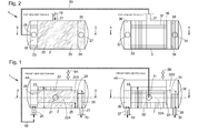
- Figures 1 and 2 schematically show a system 1 (comprising a first separator 2 and a second separator 3) for separating a feed stream 10 comprising at least three liquid phases (the density of the first liquid phase being greater than the density of the second liquid phase and the density of the second liquid phase being greater than the density of the third liquid phase) into at least three different liquid streams.
- the feed stream 10 is obtained from a well (not shown) that has been subjected to chemical EOR.
- the feed stream 10 is separated in the system 1 to obtain three liquid phases which are removed from the system 1; the first liquid phase comprises water, the second liquid phase comprises an emulsion of water and oil and the third liquid phase comprises oil.
- the first separator 2 and second separator 3 both have a substantially cylindrical shaped horizontally oriented outer walls 4A and 4B.
- the first separator 2 comprises an inlet 21 for receiving the feed stream 10, which inlet 21 is typically positioned at the side of the first separator 2 and two outlets 27 and 29 (for respectively water and a stream 50 comprising oil and an emulsion of water and oil).
- the second separator 3 comprises an inlet 31 for receiving stream 50, which inlet 31 is typically positioned at the side of the second separator 3 and two outlets 37 and 39 (for respectively oil and an emulsion of water and oil).
- the first separator 2 and second separator 3 may have further inlets and outlets if needed, e.g. for feeding or removing further liquid (typically at the bottom of the separators) or gaseous streams (typically at the top of the separators, such as degassing outlets 5A and 5B).
- first separator 2 comprises first, second and third compartments 22,26,28 and the second separator 3 comprises first, second and third compartments 32,36,38. Again, further compartments may be present, if needed.
- the first compartment 22 has a first overflow weir 23, a second overflow weir 24 and an underflow weir 25.
- the underflow weir 25 divides the first compartment 22 into first and second zones 22A and 22B.
- the volume contained in zone 22A between the first overflow weir 23 and the underflow 25 is typically above 1000 liter ( 1 ).
- the second overflow weir 24 is preferably positioned lower than the first overflow weir 23.
- the second overflow weir 24 is positioned downstream of the underflow weir 25, when determined for the first liquid phase (having the highest density in first compartment 22) that is to overflow the second overflow weir 24 from zone 22B to enter second compartment 26.
- the second compartment 26 can receive liquid (i.e. the first liquid phase) present in zone 22B and overflowing the second overflow weir 24 of the first compartment 22.
- the second compartment 26 has an outlet 27 for removing the first liquid phase from the first separator 2 of the system 1.
- the third compartment 28 can receive liquid (i.e. second and third liquid phases) present in zone 22A and overflowing the first overflow weir 23 of the first compartment 22.
- the third compartment 28 has an outlet 29 for removing the second and third liquid phase from the first separator 2 as stream 50; stream 50 is fed into the second separator 3 at inlet 31.
- the first compartment 32 has a first overflow weir 33, a second overflow weir 34 and an underflow weir 35.
- the underflow weir 35 divides the first compartment 32 into first and second zones 32A and 32B.
- the volume contained in zone 32A between the first overflow weir 33 and the underflow 35 is typically above 1000 liter ( 1 ).
- the second overflow weir 34 is preferably positioned lower than the first overflow weir 33.
- the second overflow weir 34 is positioned downstream of the underflow weir 35, when determined for the second liquid phase (having the highest density in first compartment 32 of the second separator 3) that is to overflow the second overflow weir 34 from zone 32B to enter third compartment 38.
- the third compartment 38 can receive liquid (i.e. the second liquid phase) present in zone 32B and overflowing the second overflow weir 34 of the first compartment 32.
- the third compartment 38 has an outlet 39 for removing the second liquid phase as stream 30 from the second separator 3 of the system 1.
- the second compartment 36 can receive liquid (i.e. third liquid phases) present in zone 32A and overflowing the first overflow weir 33 of the first compartment 32.
- the second compartment 36 has an outlet 37 for removing the third liquid phase as stream 40 from the second separator 2 of the system 1.
- the inlets 21,31 feed into the first compartments 22,32, and preferably in zones 22A,32A between the first overflow weirs 23,33 and the underflow weirs 25,35 of the first compartments 22,32.
- the overflow and underflow weirs comprise substantially vertically arranged baffles.
- the overflow weirs are connected to the bottom wall of the first and second separators 2,3, whilst the underflow weirs are connected to the top wall of the first and second separators 2,3.
- the feed stream 10 (indicated as "bulk” in the Figures) is fed at the inlet 21 of the first separator 2, into the first compartment 22 thereof.
- the feed stream is obtained from a well subjected to chemical EOR at least three liquid phases are removed from the system 1; the first liquid phase comprises water, the second liquid phase comprises an emulsion of water and oil and the third liquid phase comprises oil. Further phases such as liquid phases and gaseous phases may be present in the feed stream 10, although any solid material is preferably removed in advance.
- mixtures of phases may be present which separate by means of gravitation whilst being processed in the system 1.
- the first liquid phase (water; being the heaviest phase) at least partially underflows weir 25 of the first compartment 22 of the first separator 2 and is - from zone 22B - allowed to overflow the second overflow weir 24 of the first compartment 22 to enter the second compartment 26. Subsequently, the first liquid phase in the second compartment 26 is removed from the system 1 as stream 20 via the outlet 27.
- the second liquid phase (emulsion of water and oil) and the third liquid phases (oil) overflow - from zone 22A - the first overflow weir 23 of the first compartment 22 to enter the third compartment 28; the second and third liquid phases are removed from the third compartment 28 of the first separator 2 as stream 50 at outlet 29 and fed into the first inlet 31 of the second separator 3 into the first compartment 32 thereof.
- the second liquid phase (emulsion of water and oil; being the heaviest phase in first compartment 32) at least partially underflows weir 35 of the first compartment 32 and is - from zone 32B of the third compartment 32 - allowed to overflow the second overflow weir 34 of the first compartment 32 to enter the third compartment 38.
- the second liquid phase (emulsion of water and oil) in the third compartment 38 is removed from the system 1 as stream 30 via outlet 39.
- the emulsion of water and oil may be subjected to further treatment in order to remove the oil therefrom, such as by increasing or lowering the pH, removing the detergents, etc.
- zone 32A of the first compartment 32 the third liquid phase (oil) is allowed to overflow the first overflow weir 33 of the first compartment 32 to enter the second compartment 36.
- the third liquid phase (oil) in the third compartment 36 is removed from the system 1 as stream 40 via outlet 37.
- Fig. 3 schematically shows a schematic side view of a second embodiment of a system 1 in accordance with the present invention, in which the first and second separators 2,3 are in the form of a tank and hence have a substantially cylindrical shaped vertically oriented outer walls 4A and 4B.
- the feed stream 10 preferably has a temperature below the boiling temperature of water at the prevailing pressure, preferably in the range of from 30 to 95°C, preferably from 50 to 90°C, in order to expedite the separation between the water and the other liquid phases.
- the system 1 may comprises heaters in e.g. zone 22A.
- the first and second separators 2,3 may have inlets for gases or liquids which may help in separation of the various liquid phases.
Landscapes
- Chemical & Material Sciences (AREA)
- Engineering & Computer Science (AREA)
- Life Sciences & Earth Sciences (AREA)
- Oil, Petroleum & Natural Gas (AREA)
- Mining & Mineral Resources (AREA)
- Geology (AREA)
- Chemical Kinetics & Catalysis (AREA)
- Physics & Mathematics (AREA)
- Environmental & Geological Engineering (AREA)
- General Chemical & Material Sciences (AREA)
- Fluid Mechanics (AREA)
- Organic Chemistry (AREA)
- General Life Sciences & Earth Sciences (AREA)
- Geochemistry & Mineralogy (AREA)
- Wood Science & Technology (AREA)
- Thermal Sciences (AREA)
- Production Of Liquid Hydrocarbon Mixture For Refining Petroleum (AREA)
Abstract
The present invention provides a system (1) for separating a feed stream (10) comprising at least three liquid phases into at least three different liquid streams (20,30,40), the system (1) comprising a first separator (2) and a second separator (3), wherein
- the first separator (2) comprises: an inlet (21) for receiving the feed stream (10); a first compartment (22) having a first overflow weir (23), a second overflow weir (24) and an underflow weir (25); a second compartment (26) that can receive liquid overflowing the second overflow weir (24) of the first compartment (22), the second compartment (26) having an outlet (27); a third compartment (28) that can receive liquid overflowing the first overflow weir (23) of the first compartment (22), the third compartment (28) having an outlet (29); and
- the second separator (3) comprises: an inlet (31) for receiving fluid leaving the outlet (29) of the third compartment (28) of the first separator (2); a first compartment (32) having a first overflow weir (33), a second overflow weir (34) and an underflow weir (35); a second compartment (36) that can receive liquid overflowing the first overflow weir (33) of the first compartment (32), the second compartment (36) having an outlet (37); a third compartment (38) that can receive liquid overflowing the second overflow weir (34) of the first compartment (32), the third compartment (38) having an outlet (39).
- the first separator (2) comprises: an inlet (21) for receiving the feed stream (10); a first compartment (22) having a first overflow weir (23), a second overflow weir (24) and an underflow weir (25); a second compartment (26) that can receive liquid overflowing the second overflow weir (24) of the first compartment (22), the second compartment (26) having an outlet (27); a third compartment (28) that can receive liquid overflowing the first overflow weir (23) of the first compartment (22), the third compartment (28) having an outlet (29); and
- the second separator (3) comprises: an inlet (31) for receiving fluid leaving the outlet (29) of the third compartment (28) of the first separator (2); a first compartment (32) having a first overflow weir (33), a second overflow weir (34) and an underflow weir (35); a second compartment (36) that can receive liquid overflowing the first overflow weir (33) of the first compartment (32), the second compartment (36) having an outlet (37); a third compartment (38) that can receive liquid overflowing the second overflow weir (34) of the first compartment (32), the third compartment (38) having an outlet (39).
Description
- The present invention relates to a system and a method for separating a feed stream comprising at least three liquid phases.
- In the prior art various separators are known, such as gas/liquid separators, gas/solid separators, liquid/solid separators, etc.
- There is a constant desire for new and alternative separators.
- It is an object of the present invention to provide an alternative separation system, in particular for separating a feed stream comprising at least three liquid phases.
- It is a further object of the present invention to provide a system for separating a feed stream that has been obtained from an oil well that has been subjected to chemical Enhanced Oil Recovery (chemical EOR).
- One or more of the above or other objects are achieved according to the present invention by providing a system for separating a feed stream comprising at least three liquid phases into at least three different liquid streams, the system comprising a first separator and a second separator, wherein
- the first separator comprises: an inlet for receiving the feed stream; a first compartment having a first overflow weir, a second overflow weir and an underflow weir; a second compartment that can receive liquid overflowing the second overflow weir of the first compartment, the second compartment having an outlet; a third compartment that can receive liquid overflowing the first overflow weir of the first compartment, the third compartment having an outlet; and
- the second separator comprises: an inlet for receiving fluid leaving the outlet of the third compartment of the first separator; a first compartment having a first overflow weir, a second overflow weir and an underflow weir; a second compartment that can receive liquid overflowing the first overflow weir of the first compartment, the second compartment having an outlet; a third compartment that can receive liquid overflowing the second overflow weir of the first compartment, the third compartment having an outlet.
- An advantage of the present invention is that feed streams comprising at least three liquid phases can be separated in a very simple way, minimizing or even avoiding the need of flow controllers, level controllers and the like and avoiding risk of re-emulsification.
- A further advantage of the present invention is that, in particular in the case wherein the feed stream has been obtained from an oil well that has been subjected to chemical EOR, the majority of the water and oil can be removed and the processing of the phase comprising an emulsion of water and oil (possibly also containing detergents and/or chemicals as used during the EOR) can be performed on a much smaller stream.
- According to the present invention, the feed stream to be separated comprises at least three different liquid phases. In addition to the at least three liquid phases, the feed stream may contain one or more gases as well as solid materials, although it is preferred that any solid material has been removed before entering the separator to avoid clogging. Typically, the feed stream comprises at least three liquid phases having a different density. Preferably, the feed stream comprises at least a first, second and third liquid phase wherein the density of the first liquid phase is greater than the density of the second liquid phase and wherein the density of the second liquid phase is greater than the density of the third liquid phase.
- Preferably the feed stream has been obtained from an oil well that has been subjected to chemical EOR. As chemical EOR is known in the prior art, this is not further described here. An exemplary chemical EOR process has been described in J.R. Barnes et al., "Developments of Surfactants for Chemical Flooding at Difficult Reservoir Conditions", SPE-113313-PP and presented at the 2008 SPE Improved Oil Recovery Symposium as held in Tulsa, Oklahoma, US on 19-23 April 2008, the teaching of which is hereby incorporated by reference.
- Preferably, the feed stream to be separated comprises at least water as the first liquid phase, an emulsion of water and oil as the second liquid phase and oil as the third liquid phase. According to the present invention, the term "oil" is intended to refer to the liquid hydrocarbon-containing composition produced in a well; the person skilled in the art will understand that the composition of the liquid hydrocarbon-containing composition may vary broadly (e.g. dependent on the well) and may contain some solid material dispersed in it.
- It is preferred according to the present invention that the inlet of the first separator feeds into the first compartment, preferably between the first overflow weir and the underflow weir of the first compartment. This prevents or minimizes the chance that the first liquid phase that is intended to overflow the second overflow weir of the first compartment in fact overflows the first overflow weir of the first compartment thereby entering the third compartment. Similarly, it is preferred that the inlet of the second separator feeds into the first compartment, preferably between the first overflow weir and the underflow weir of the first compartment.
- The person skilled in the art readily understands that the overflow weirs and underflow weirs can be embodied in various ways. In a preferred embodiment the overflow and underflow weirs comprise substantially vertically arranged baffles which may be connected to the inner wall of the separator.
- Also, each of the first and second separators may take various shapes, e.g. having a substantially cylindrical shaped horizontally or vertically oriented outer wall. Preferably the first and second separator have a substantially cylindrical shaped horizontally oriented outer wall.
- In another aspect the present invention provides a method for separating a feed stream comprising at least three liquid phases into at least three different liquid streams, the method comprising at least the steps of:
- (a) feeding the feed stream at an inlet of a first separator into a first compartment thereof;
- (b) allowing a first liquid phase to overflow a second overflow weir of the first compartment to enter a second compartment and removing the first liquid phase in the second compartment from the first separator via an outlet;
- (c) allowing a second and third liquid phase to overflow a first overflow weir of the first compartment to enter a third compartment;
- (d) removing the second and third liquid phase in the third compartment from the first separator via an outlet and feeding it at a first inlet of a second separator into a first compartment thereof;
- (e) allowing the second liquid phase to overflow a second overflow weir of the first compartment to enter a third compartment and removing the second liquid phase in the third compartment from the second separator via an outlet;
- (f) allowing the third liquid phase to overflow a first overflow weir of the first compartment to enter a second compartment and removing the third liquid phase in the second compartment from the second separator via an outlet.
- Preferably the feed stream entering the first compartment of the first and second separators has a low velocity in order to avoid that some of the phases (such as the water and oil phases) undergo emulsification; a typical velocity for the feed stream is below 1.0 m/s, preferably below 0.5 m/s.
- As indicated above, preferably the density of the first liquid phase is greater than the density of the second liquid phase and wherein the density of the second liquid phase is greater than the density of the third liquid phase. Also it is preferred that the first liquid phase comprises water, the second liquid phase comprises an emulsion of water and oil and the third liquid phase comprises oil. It is even further preferred that the feed stream is obtained from a well that has been subjected to chemical Enhanced Oil Recovery (chemical EOR).
- According to a preferred embodiment the first liquid phase, after being fed to the first compartment and before overflowing the second overflow weir of the first compartment of the first separator underflows an underflow weir. Also it is preferred that the second liquid phase, after entering the first compartment and before overflowing the second overflow weir of the first compartment of the second separator underflows an underflow weir.
- According to an especially preferred embodiment of the present invention the feed stream has a temperature below the boiling temperature of water at the prevailing pressure. Preferably, the separator according to the present invention is operated at a pressure of from ambient pressure to about 10 bar, preferably below 5 bar.
- Hereinafter the invention will be further illustrated by the following non-limiting drawing. Herein shows:
-
Fig. 1 schematically a schematic side view of a first embodiment of a system in accordance with the present invention; -
Fig. 2 schematically a schematic top view of the separator ofFig. 1 ; and -
Fig. 3 schematically a schematic side view of a second embodiment of a system in accordance with the present invention. - For the purpose of this description, same reference numbers refer to similar components.
-
Figures 1 and 2 schematically show a system 1 (comprising afirst separator 2 and a second separator 3) for separating afeed stream 10 comprising at least three liquid phases (the density of the first liquid phase being greater than the density of the second liquid phase and the density of the second liquid phase being greater than the density of the third liquid phase) into at least three different liquid streams. - Preferably, the
feed stream 10 is obtained from a well (not shown) that has been subjected to chemical EOR. In the latter case, thefeed stream 10 is separated in the system 1 to obtain three liquid phases which are removed from the system 1; the first liquid phase comprises water, the second liquid phase comprises an emulsion of water and oil and the third liquid phase comprises oil. - In the embodiment of
Figure 1 , thefirst separator 2 andsecond separator 3 both have a substantially cylindrical shaped horizontally orientedouter walls first separator 2 comprises aninlet 21 for receiving thefeed stream 10, whichinlet 21 is typically positioned at the side of thefirst separator 2 and twooutlets 27 and 29 (for respectively water and astream 50 comprising oil and an emulsion of water and oil). Thesecond separator 3 comprises aninlet 31 for receivingstream 50, whichinlet 31 is typically positioned at the side of thesecond separator 3 and twooutlets 37 and 39 (for respectively oil and an emulsion of water and oil). It goes without saying that thefirst separator 2 andsecond separator 3 may have further inlets and outlets if needed, e.g. for feeding or removing further liquid (typically at the bottom of the separators) or gaseous streams (typically at the top of the separators, such as degassingoutlets - Further, the
first separator 2 comprises first, second andthird compartments second separator 3 comprises first, second andthird compartments - With respect to the
first separator 2, thefirst compartment 22 has afirst overflow weir 23, asecond overflow weir 24 and anunderflow weir 25. Theunderflow weir 25 divides thefirst compartment 22 into first andsecond zones zone 22A between thefirst overflow weir 23 and theunderflow 25 is typically above 1000 liter (1). Thesecond overflow weir 24 is preferably positioned lower than thefirst overflow weir 23. Also, thesecond overflow weir 24 is positioned downstream of theunderflow weir 25, when determined for the first liquid phase (having the highest density in first compartment 22) that is to overflow thesecond overflow weir 24 fromzone 22B to entersecond compartment 26. Thesecond compartment 26 can receive liquid (i.e. the first liquid phase) present inzone 22B and overflowing thesecond overflow weir 24 of thefirst compartment 22. Thesecond compartment 26 has anoutlet 27 for removing the first liquid phase from thefirst separator 2 of the system 1. Thethird compartment 28 can receive liquid (i.e. second and third liquid phases) present inzone 22A and overflowing thefirst overflow weir 23 of thefirst compartment 22. Thethird compartment 28 has anoutlet 29 for removing the second and third liquid phase from thefirst separator 2 asstream 50;stream 50 is fed into thesecond separator 3 atinlet 31. - Similar to the
first separator 2, with respect to thesecond separator 3 thefirst compartment 32 has afirst overflow weir 33, asecond overflow weir 34 and anunderflow weir 35. The underflowweir 35 divides thefirst compartment 32 into first andsecond zones zone 32A between thefirst overflow weir 33 and theunderflow 35 is typically above 1000 liter (1). Thesecond overflow weir 34 is preferably positioned lower than thefirst overflow weir 33. Also, thesecond overflow weir 34 is positioned downstream of theunderflow weir 35, when determined for the second liquid phase (having the highest density infirst compartment 32 of the second separator 3) that is to overflow thesecond overflow weir 34 fromzone 32B to enterthird compartment 38. Thethird compartment 38 can receive liquid (i.e. the second liquid phase) present inzone 32B and overflowing thesecond overflow weir 34 of thefirst compartment 32. Thethird compartment 38 has anoutlet 39 for removing the second liquid phase asstream 30 from thesecond separator 3 of the system 1. Thesecond compartment 36 can receive liquid (i.e. third liquid phases) present inzone 32A and overflowing thefirst overflow weir 33 of thefirst compartment 32. Thesecond compartment 36 has anoutlet 37 for removing the third liquid phase asstream 40 from thesecond separator 2 of the system 1. - Preferably, and as shown in
Fig. 1 , theinlets first compartments zones first overflow weirs underflow weirs first compartments Figs. 1 and 2 , the overflow weirs are connected to the bottom wall of the first andsecond separators second separators - During use of the system 1 of
Figures 1 and 2 , the feed stream 10 (indicated as "bulk" in the Figures) is fed at theinlet 21 of thefirst separator 2, into thefirst compartment 22 thereof. In the case that the feed stream is obtained from a well subjected to chemical EOR at least three liquid phases are removed from the system 1; the first liquid phase comprises water, the second liquid phase comprises an emulsion of water and oil and the third liquid phase comprises oil. Further phases such as liquid phases and gaseous phases may be present in thefeed stream 10, although any solid material is preferably removed in advance. Also some mixtures of phases (such as the "bulk" fed atinlet 21 and the (mixture of) "oil and emulsion" present in streamthird compartment 28 of thefirst separator 2,stream 50 and thefirst compartment 32 of the second separator 3) may be present which separate by means of gravitation whilst being processed in the system 1. - The first liquid phase (water; being the heaviest phase) at least partially
underflows weir 25 of thefirst compartment 22 of thefirst separator 2 and is - fromzone 22B - allowed to overflow thesecond overflow weir 24 of thefirst compartment 22 to enter thesecond compartment 26. Subsequently, the first liquid phase in thesecond compartment 26 is removed from the system 1 asstream 20 via theoutlet 27. - The second liquid phase (emulsion of water and oil) and the third liquid phases (oil) overflow - from
zone 22A - thefirst overflow weir 23 of thefirst compartment 22 to enter thethird compartment 28; the second and third liquid phases are removed from thethird compartment 28 of thefirst separator 2 asstream 50 atoutlet 29 and fed into thefirst inlet 31 of thesecond separator 3 into thefirst compartment 32 thereof. The second liquid phase (emulsion of water and oil; being the heaviest phase in first compartment 32) at least partiallyunderflows weir 35 of thefirst compartment 32 and is - fromzone 32B of the third compartment 32 - allowed to overflow thesecond overflow weir 34 of thefirst compartment 32 to enter thethird compartment 38. The second liquid phase (emulsion of water and oil) in thethird compartment 38 is removed from the system 1 asstream 30 viaoutlet 39. The emulsion of water and oil may be subjected to further treatment in order to remove the oil therefrom, such as by increasing or lowering the pH, removing the detergents, etc. - In
zone 32A of thefirst compartment 32 the third liquid phase (oil) is allowed to overflow thefirst overflow weir 33 of thefirst compartment 32 to enter thesecond compartment 36. The third liquid phase (oil) in thethird compartment 36 is removed from the system 1 asstream 40 viaoutlet 37. -
Fig. 3 schematically shows a schematic side view of a second embodiment of a system 1 in accordance with the present invention, in which the first andsecond separators outer walls - The person skilled in the art will readily understand that many modifications may be made without departing from the scope of the invention. As an example, the
feed stream 10 preferably has a temperature below the boiling temperature of water at the prevailing pressure, preferably in the range of from 30 to 95°C, preferably from 50 to 90°C, in order to expedite the separation between the water and the other liquid phases. - Also, although the system 1 according to the present invention is preferably kept as simple as possible, the system 1 may comprises heaters in
e.g. zone 22A. Also, the first andsecond separators
Claims (11)
- A system (1) for separating a feed stream (10) comprising at least three liquid phases into at least three different liquid streams (20,30,40), the system (1) comprising a first separator (2) and a second separator (3), wherein- the first separator (2) comprises: an inlet (21) for receiving the feed stream (10); a first compartment (22) having a first overflow weir (23), a second overflow weir (24) and an underflow weir (25); a second compartment (26) that can receive liquid overflowing the second overflow weir (24) of the first compartment (22), the second compartment (26) having an outlet (27); a third compartment (28) that can receive liquid overflowing the first overflow weir (23) of the first compartment (22), the third compartment (28) having an outlet (29); and- the second separator (3) comprises: an inlet (31) for receiving fluid leaving the outlet (29) of the third compartment (28) of the first separator (2); a first compartment (32) having a first overflow weir (33), a second overflow weir (34) and an underflow weir (35); a second compartment (36) that can receive liquid overflowing the first overflow weir (33) of the first compartment (32), the second compartment (36) having an outlet (37); a third compartment (38) that can receive liquid overflowing the second overflow weir (34) of the first compartment (32), the third compartment (38) having an outlet (39).
- The system (1) according to claim 1, wherein the inlet (21) of the first separator (2) feeds into the first compartment (22), preferably between the first overflow weir (23) and the underflow weir (25) of the first compartment (22).
- The system (1) according to claim 1 or 2, wherein the inlet (31) of the second separator (3) feeds into the first compartment (32), preferably between the first overflow weir (33) and the underflow weir (35) of the first compartment (32).
- The system (1) according to any one of claim 1-3, wherein the overflow and underflow weirs comprise substantially vertically arranged baffles.
- A method for separating a feed stream (10) comprising at least three liquid phases into at least three different liquid streams (20,30,40), the method comprising at least the steps of:(a) feeding the feed stream (10) at an inlet (21) of a first separator (2) into a first compartment (22) thereof;(b) allowing a first liquid phase to overflow a second overflow weir (24) of the first compartment (22) to enter a second compartment (26) and removing the first liquid phase in the second compartment (26) from the first separator (2) via an outlet (27);(c) allowing a second and third liquid phase to overflow a first overflow weir (23) of the first compartment (22) to enter a third compartment (28);(d) removing the second and third liquid phase in the third compartment (28) from the first separator (2) via an outlet (29) and feeding it at a first inlet (31) of a second separator (3) into a first compartment (32) thereof;(e) allowing the second liquid phase to overflow a second overflow weir (34) of the first compartment (32) to enter a third compartment (38) and removing the second liquid phase in the third compartment (38) from the second separator (3) via an outlet (39);(f) allowing the third liquid phase to overflow a first overflow weir (33) of the first compartment (32) to enter a second compartment (36) and removing the third liquid phase in the second compartment (36) from the second separator (3) via an outlet (37).
- The method according to claim 5, wherein the density of the first liquid phase is greater than the density of the second liquid phase and wherein the density of the second liquid phase is greater than the density of the third liquid phase.
- The method according to claim 5 or 6, wherein the first liquid phase comprises water, the second liquid phase comprises an emulsion of water and oil and the third liquid phase comprises oil.
- The method according to any one of claims 5-7, wherein the feed stream (10) is obtained from a well that has been subjected to chemical Enhanced Oil Recovery (chemical EOR).
- The method according to any one of claims 5-8, wherein the first liquid phase, after being fed to the first compartment (22) and before overflowing the second overflow weir (24) of the first compartment (22) of the first separator (2) underflows an underflow weir (25).
- The method according to any one of claims 5-9, wherein the second liquid phase, after entering the first compartment (32) and before overflowing the second overflow weir (34) of the first compartment (32) of the second separator (3) underflows an underflow weir (35).
- The method according to any one of claims 5-10, wherein the feed stream (10) has a temperature below the boiling temperature of water at the prevailing pressure, preferably in the range of from 30 to 95°C.
Priority Applications (1)
| Application Number | Priority Date | Filing Date | Title |
|---|---|---|---|
| EP11153630A EP2397207A1 (en) | 2011-02-08 | 2011-02-08 | System for separating a feed stream comprising at least three liquid phases |
Applications Claiming Priority (1)
| Application Number | Priority Date | Filing Date | Title |
|---|---|---|---|
| EP11153630A EP2397207A1 (en) | 2011-02-08 | 2011-02-08 | System for separating a feed stream comprising at least three liquid phases |
Publications (1)
| Publication Number | Publication Date |
|---|---|
| EP2397207A1 true EP2397207A1 (en) | 2011-12-21 |
Family
ID=43923660
Family Applications (1)
| Application Number | Title | Priority Date | Filing Date |
|---|---|---|---|
| EP11153630A Withdrawn EP2397207A1 (en) | 2011-02-08 | 2011-02-08 | System for separating a feed stream comprising at least three liquid phases |
Country Status (1)
| Country | Link |
|---|---|
| EP (1) | EP2397207A1 (en) |
Cited By (1)
| Publication number | Priority date | Publication date | Assignee | Title |
|---|---|---|---|---|
| CN103372331A (en) * | 2012-04-16 | 2013-10-30 | 中国石油化工集团公司 | Oil water separation device and method |
Citations (4)
| Publication number | Priority date | Publication date | Assignee | Title |
|---|---|---|---|---|
| NL7413907A (en) * | 1974-10-24 | 1976-04-27 | Shell Int Research | Oil and water separating chamber for drainage collecting tank - "V"-shaped baffle plates increase active surface area |
| US4689155A (en) * | 1983-08-29 | 1987-08-25 | Chevron Research Company | Method for purifying solids-stabilized emulsions |
| US5656173A (en) * | 1996-03-05 | 1997-08-12 | National Tank Company | Method of removing dispersed oil from an oil in water emulsion employing aerated solutions within a coalescing media |
| DE19651680A1 (en) * | 1996-12-12 | 1998-06-18 | Obm Oberdorfer Maschinenfabrik | Oil separator for cutting fluids having central vessel with oil coagulation mat |
-
2011
- 2011-02-08 EP EP11153630A patent/EP2397207A1/en not_active Withdrawn
Patent Citations (4)
| Publication number | Priority date | Publication date | Assignee | Title |
|---|---|---|---|---|
| NL7413907A (en) * | 1974-10-24 | 1976-04-27 | Shell Int Research | Oil and water separating chamber for drainage collecting tank - "V"-shaped baffle plates increase active surface area |
| US4689155A (en) * | 1983-08-29 | 1987-08-25 | Chevron Research Company | Method for purifying solids-stabilized emulsions |
| US5656173A (en) * | 1996-03-05 | 1997-08-12 | National Tank Company | Method of removing dispersed oil from an oil in water emulsion employing aerated solutions within a coalescing media |
| DE19651680A1 (en) * | 1996-12-12 | 1998-06-18 | Obm Oberdorfer Maschinenfabrik | Oil separator for cutting fluids having central vessel with oil coagulation mat |
Non-Patent Citations (1)
| Title |
|---|
| J.R. BARNES ET AL.: "Developments of Surfactants for Chemical Flooding at Difficult Reservoir Conditions", SPE-113313-PP AND PRESENTED AT THE 2008 SPE IMPROVED OIL RECOVERY SYMPOSIUM AS HELD IN TULSA, OKLAHOMA, US ON 19-23 APRIL 2008, 19 April 2008 (2008-04-19) |
Cited By (2)
| Publication number | Priority date | Publication date | Assignee | Title |
|---|---|---|---|---|
| CN103372331A (en) * | 2012-04-16 | 2013-10-30 | 中国石油化工集团公司 | Oil water separation device and method |
| CN103372331B (en) * | 2012-04-16 | 2015-05-13 | 中国石油化工集团公司 | Oil water separation device and method |
Similar Documents
| Publication | Publication Date | Title |
|---|---|---|
| KR101217363B1 (en) | A method and device for converting horizontal tanks into gas flotation separators | |
| EP1284800B1 (en) | A method and a system for separating a mixture | |
| DK179274B1 (en) | Split flow pipe separator | |
| US10913013B2 (en) | System and method to process effluent brine and interface rag from an oil dehydration/desalting system | |
| EP2355913B1 (en) | Separation method for immiscible fluids | |
| KR101935884B1 (en) | Spherical separation device and method for separation | |
| JP2000061205A (en) | Liquid separation method and apparatus | |
| NO329085B1 (en) | Process and apparatus for separating fluid phases, and their applications | |
| EP3038725B1 (en) | Gas flotation tank | |
| GB2451965A (en) | A method for separating a multiphase fluid stream comprising a heavier fluid component and a lighter fluid component | |
| US9174223B2 (en) | Compact separation apparatus | |
| WO2014058480A1 (en) | Multiphase separation system | |
| EP2397206A1 (en) | Separator for separating a feed stream comprising at least three liquid phases | |
| RU125483U1 (en) | THREE PHASE SEPARATOR | |
| JP2008264745A (en) | Oil/water separator | |
| WO2016209086A1 (en) | Separator system and method for breaking down a dispersion band | |
| CA2527543C (en) | Vessel and method for treating contaminated water | |
| EP1559465B1 (en) | Small droplets recovery system | |
| US20180127288A1 (en) | Gas flotation tank | |
| WO2020225342A1 (en) | Multi stage contactor | |
| WO2012030503A1 (en) | Method and apparatus to enhance separation performance of a lean and low mean size dispersed phase from a continuous phase | |
| CA3008916A1 (en) | Separation of water and oil from a production stream | |
| MXPA06008230A (en) | Small droplets recovery system | |
| WO2013017939A2 (en) | Device and method for separating oil/fat from water | |
| HK1220158B (en) | Gas flotation tank |
Legal Events
| Date | Code | Title | Description |
|---|---|---|---|
| AK | Designated contracting states |
Kind code of ref document: A1 Designated state(s): AL AT BE BG CH CY CZ DE DK EE ES FI FR GB GR HR HU IE IS IT LI LT LU LV MC MK MT NL NO PL PT RO RS SE SI SK SM TR |
|
| AX | Request for extension of the european patent |
Extension state: BA ME |
|
| PUAI | Public reference made under article 153(3) epc to a published international application that has entered the european phase |
Free format text: ORIGINAL CODE: 0009012 |
|
| STAA | Information on the status of an ep patent application or granted ep patent |
Free format text: STATUS: THE APPLICATION HAS BEEN WITHDRAWN |
|
| 18W | Application withdrawn |
Effective date: 20120221 |