EP1559465B1 - Small droplets recovery system - Google Patents
Small droplets recovery system Download PDFInfo
- Publication number
- EP1559465B1 EP1559465B1 EP04290203.1A EP04290203A EP1559465B1 EP 1559465 B1 EP1559465 B1 EP 1559465B1 EP 04290203 A EP04290203 A EP 04290203A EP 1559465 B1 EP1559465 B1 EP 1559465B1
- Authority
- EP
- European Patent Office
- Prior art keywords
- large drops
- fluid
- coalescing element
- flow
- bed
- Prior art date
- Legal status (The legal status is an assumption and is not a legal conclusion. Google has not performed a legal analysis and makes no representation as to the accuracy of the status listed.)
- Expired - Lifetime
Links
- 238000011084 recovery Methods 0.000 title claims description 29
- 239000012530 fluid Substances 0.000 claims description 72
- XLYOFNOQVPJJNP-UHFFFAOYSA-N water Substances O XLYOFNOQVPJJNP-UHFFFAOYSA-N 0.000 claims description 56
- 239000000839 emulsion Substances 0.000 claims description 49
- 238000012856 packing Methods 0.000 claims description 39
- 229930195733 hydrocarbon Natural products 0.000 claims description 20
- 150000002430 hydrocarbons Chemical class 0.000 claims description 20
- 230000002745 absorbent Effects 0.000 claims description 14
- 239000002250 absorbent Substances 0.000 claims description 14
- 239000004215 Carbon black (E152) Substances 0.000 claims description 13
- 238000000034 method Methods 0.000 claims description 12
- 239000008213 purified water Substances 0.000 claims description 12
- 229920005830 Polyurethane Foam Polymers 0.000 claims description 10
- 239000000463 material Substances 0.000 claims description 10
- 239000011496 polyurethane foam Substances 0.000 claims description 10
- 229920000642 polymer Polymers 0.000 claims description 9
- 238000011144 upstream manufacturing Methods 0.000 claims description 9
- 239000012071 phase Substances 0.000 description 70
- 239000010410 layer Substances 0.000 description 13
- 230000005484 gravity Effects 0.000 description 10
- 238000002203 pretreatment Methods 0.000 description 5
- 238000004519 manufacturing process Methods 0.000 description 4
- 239000008346 aqueous phase Substances 0.000 description 3
- 230000000694 effects Effects 0.000 description 3
- 239000007788 liquid Substances 0.000 description 3
- 230000015572 biosynthetic process Effects 0.000 description 2
- 238000004140 cleaning Methods 0.000 description 2
- 239000002184 metal Substances 0.000 description 2
- 239000000203 mixture Substances 0.000 description 2
- 239000003208 petroleum Substances 0.000 description 2
- 229920002635 polyurethane Polymers 0.000 description 2
- 239000004814 polyurethane Substances 0.000 description 2
- 230000000717 retained effect Effects 0.000 description 2
- 239000007790 solid phase Substances 0.000 description 2
- 239000012267 brine Substances 0.000 description 1
- 230000009172 bursting Effects 0.000 description 1
- 239000006227 byproduct Substances 0.000 description 1
- 238000005119 centrifugation Methods 0.000 description 1
- 238000005516 engineering process Methods 0.000 description 1
- 230000007613 environmental effect Effects 0.000 description 1
- 238000001914 filtration Methods 0.000 description 1
- 238000009434 installation Methods 0.000 description 1
- 239000002245 particle Substances 0.000 description 1
- 239000003209 petroleum derivative Substances 0.000 description 1
- 239000000376 reactant Substances 0.000 description 1
- 238000010008 shearing Methods 0.000 description 1
- 239000002356 single layer Substances 0.000 description 1
- HPALAKNZSZLMCH-UHFFFAOYSA-M sodium;chloride;hydrate Chemical compound O.[Na+].[Cl-] HPALAKNZSZLMCH-UHFFFAOYSA-M 0.000 description 1
- 239000007787 solid Substances 0.000 description 1
- 239000004094 surface-active agent Substances 0.000 description 1
Images


Classifications
-
- B—PERFORMING OPERATIONS; TRANSPORTING
- B01—PHYSICAL OR CHEMICAL PROCESSES OR APPARATUS IN GENERAL
- B01D—SEPARATION
- B01D17/00—Separation of liquids, not provided for elsewhere, e.g. by thermal diffusion
- B01D17/02—Separation of non-miscible liquids
- B01D17/0208—Separation of non-miscible liquids by sedimentation
- B01D17/0211—Separation of non-miscible liquids by sedimentation with baffles
-
- B—PERFORMING OPERATIONS; TRANSPORTING
- B01—PHYSICAL OR CHEMICAL PROCESSES OR APPARATUS IN GENERAL
- B01D—SEPARATION
- B01D17/00—Separation of liquids, not provided for elsewhere, e.g. by thermal diffusion
- B01D17/02—Separation of non-miscible liquids
- B01D17/0208—Separation of non-miscible liquids by sedimentation
- B01D17/0214—Separation of non-miscible liquids by sedimentation with removal of one of the phases
-
- B—PERFORMING OPERATIONS; TRANSPORTING
- B01—PHYSICAL OR CHEMICAL PROCESSES OR APPARATUS IN GENERAL
- B01D—SEPARATION
- B01D17/00—Separation of liquids, not provided for elsewhere, e.g. by thermal diffusion
- B01D17/02—Separation of non-miscible liquids
- B01D17/04—Breaking emulsions
- B01D17/045—Breaking emulsions with coalescers
-
- Y—GENERAL TAGGING OF NEW TECHNOLOGICAL DEVELOPMENTS; GENERAL TAGGING OF CROSS-SECTIONAL TECHNOLOGIES SPANNING OVER SEVERAL SECTIONS OF THE IPC; TECHNICAL SUBJECTS COVERED BY FORMER USPC CROSS-REFERENCE ART COLLECTIONS [XRACs] AND DIGESTS
- Y10—TECHNICAL SUBJECTS COVERED BY FORMER USPC
- Y10S—TECHNICAL SUBJECTS COVERED BY FORMER USPC CROSS-REFERENCE ART COLLECTIONS [XRACs] AND DIGESTS
- Y10S210/00—Liquid purification or separation
- Y10S210/05—Coalescer
Definitions
- the invention relates generally to the separating of small droplets from a continuous phase of a water/hydrocarbons emulsion fluid with a coalescing element.
- Filtering a fluid comprising two non-miscible phases is a common operation.
- the fluid may be stored in a container during a given time: a first phase and a second phase may separate upon gravity. The phase having the smallest density is then collected at a surface of the fluid.
- the fluid may be under a form of an emulsion comprising a continuous phase and a dispersed phase.
- the emulsion may be relatively stable, in particular if a surfactant is added at a forming of the emulsion.
- a separator packing allows to separate a dispersed oily phase from a continuous phase.
- the separator packing comprises a plurality of plates that are made of an oleophilic material so that drops of the dispersed oily phase adhere to the plates.
- the plates are oriented in a diagonal direction in such a way that the coalesced drops move upward along the plates upon a pressure generated by a flow of the continuous phase.
- the continuous phase flows through the separator packing.
- particles of the solid phase are intercepted by the separator packing and drop at the bottom of the separator under the effect of gravity.
- the separator packing hence guides the dispersed oily phase upward, the solid phase downward and let the continuous phase flow.
- the dispersed phase is in a form of relatively small droplets, the effect of the gravity is minimized. It may hence take a relatively long time to separate an emulsion by storing it in a container. Under such circumstances, a separator packing provides a relatively low efficiency in separating small droplets from a continuous phase.
- British Patent 1 418 806 to Continental oil Co discloses a process for separating the phases of an emulsion comprised of water and of a petroleum hydrocarbon.
- the process comprises passing the emulsion through a bed of polyurethane foam.
- the hydrocarbon dispersed phase is coalesced into droplets. If the droplets are less dense than water, the droplets rise to form an hydrocarbon layer that is above a water layer. Portions of the hydrocarbon layer and of the water layer are continually drawn off, thus effecting the separating.
- FIG. 1A, FIG. 1B and FIG. 1C illustrate a coalescing of the oil droplets at a RPA bed according to prior art.
- a flow of an emulsion comprising a water continuous phase 13 and oil droplets 12 passes through RPA elements 11.
- the RPA elements 11 intercept oil droplets.
- the emulsion may still comprise free droplets 17 at an outlet of the RPA elements 11.
- the intercepted droplets 14 may, upon the flow of the emulsion, form a layer 16 at a surface of the RPA elements 11, as represented in FIG. 1B .
- a creaming of an emulsion i.e. a velocity of a given drop upon gravity is governed by Stoke's law : the large oil drops 16 move upward faster than the oil droplets (12, 17).
- FIG. 2 illustrates a system for separating oil droplets from a continuous water phase according to prior art.
- a plurality of RPA beds (27a, 27b) are provided within a vessel 28 through which an emulsion fluid comprising oil droplets (22a, 22b, 22c) among a continuous water phase 23 may flow.
- a first RPA bed 27a allows to form large oil drops 25a from the oil droplets 22a.
- An number of non retained oil droplets 22b may pass trough the first RPA bed 27a without adhering to any RPA element (not represented on FIG. 2 ) of the first RPA bed 27a.
- the large oil drops 25a move upward upon gravity faster than the oil droplets 22b.
- the large oil drops form at a surface of the water phase an oil layer 24.
- a recovery outlet, e.g. a recovery pipe 29 at the surface allows to recover the oil layer 24.
- a similar process is iterated via a second RPA bed 27b and further RPA beds (not represented on FIG. 2 ) for further cleaning if necessary. It is desirable to avoid the large oil drops 25a generated at the first RPA bed 27a to enter the second RPA bed 27b.
- the recovering of the large oil drops 25a depends on a plurality of parameters : a velocity of the flow of emulsion fluid, a density of oil, a density of water, a distance between the first RPA bed 27a and the second RPA be 27b, and a height between the large oil drop at the first RPA bed 25a and the oil layer 24.
- the RPA beds (27a, 27b) may be positioned at a relatively high distance.
- the invention relates to a system for separating a water/hydrocarbons emulsion fluid into a recovered oil fluid and a purified water fluid according to claim 1.
- the emulsion fluid comprises a continuous phase and a dispersed phase.
- the purified water fluid is essentially constituted of the continuous phase.
- the system comprises a vessel at an inlet of which the emulsion fluid may flow.
- the system further comprises one or more coalescing element. Each coalescing element allows to coalesce at least a portion of the dispersed phase into large drops further detached from the coalescing element upon a flow of the emulsion fluid.
- the system further comprises one or more guiding means. Each guiding means is associated with one coalescing element to guide the detached large drops for further recovery.
- the system further comprises one or more bed, each bed allowing to support one coalescing element.
- the system further comprises one or more recovery outlet. Each recovery outlet allows to recover the recovered fluid from large drops detached from one coalescing element.
- the guiding means is a separator packing.
- the separator packing has a structure that is adapted to allow the continuous phase to flow through the separator packing.
- each separator packing is substantially located at 10 millimeters of the associated coalescing element so as to allow a burst of bubbles of the continuous phase.
- the bubbles are surrounded by a film of the dispersed phase. The bubbles are formed between the coalescing element and the separator packing.
- the separator packing comprises a plurality of plates disposed at an output of the at least one associated coalescing to intercept the large drops.
- the dispersed phase may comprise oil droplets.
- the plurality of plates are made of an oleophilic material so that the intercepted large drops adhere to the plates
- the plurality of plates have a diagonal orientation adapted for guiding the adhered large drops upward.
- the emulsion fluid is a produced water associated with a production of hydrocarbons.
- the coalescing element is a Reusable Polymer Absorbent, being polyurethane foam shredded in small flakes so as to increase a surface area offered to a flow.
- the invention provides a method for recovering from a water/hydrocarbons emulsion fluid a recovered fluid and a purified water fluid according to claim 6.
- the emulsion fluid comprises a continuous phase and a dispersed phase.
- the purified water fluid is essentially constituted of the continuous phase.
- the method comprises providing a flow of at least a portion of the emulsion fluid through at least one bed within a vessel. Each bed supports a coalescing element made of Reusable Polymer Absorbent material, being polyurethane foam shredded in small flakes so as to increase a surface area offered to a flow, whereby at least a portion of the dispersed phase coalesces into large drops.
- the coalesced large drops are detached from each bed by means of a flow velocity.
- the detached large drops are guided with at least one guiding means.
- the at least one guiding means is associated with the at least one bed.
- the method further comprises recovering the recovered fluid from the guided large drops.
- the method further comprises repeating the coalescing, the detaching, the guiding and the recovering at a further location of the vessel.
- the dispersed phase comprises droplets of oil.
- At least one bed supports a coalescing element.
- the coalescing element allows to coalesce at least a portion of the dispersed phase into large drops detached from the coalescing element upon a flow of the continuous phase.
- the system further comprises at least one weir located along the at least one bed at an upstream side of the at least one bed. Each weir allows to prevent the coalesced portion to flow through an associated bed.
- system further comprises a recovery outlet located at the upstream side of the bed, the recovery outlet allowing to recover the coalesced portion.
- a vessel system comprising a plurality of RPA beds - or any bed supporting coalescing element through which an emulsion may flow - allows to separate small droplets of the emulsion from a continuous phase.
- the coalescing element allows to generate large drops by coalescing the droplets.
- the large drops are detached from the coalescing element upon a flow of the emulsion.
- the large drops move to a surface of the continuous phase upon gravity and may be easily recovered.
- Each bed of coalescing element needs to be positioned at a relatively high distance from others beds so as to avoid the large drops generated at a determined bed to enter a further bed before being recovered.
- the vessel system may have a relatively long length.
- Such vessel system may for example be used in petroleum industry.
- the production of hydrocarbons is usually associated with the generation of a produced water.
- the produced water needs to be cleaned from oil before disposal.
- the vessel system allows to separate a last fraction of oil present in the water as an emulsion.
- the length of the vessel is a crucial factor as a vessel having a relatively short length is easier to accommodate.
- a separating system allowing to separate small droplets from a continuous phase of an emulsion that has a relatively short length so as to allow an easier manipulating.
- Such a separating system may be used in the petroleum industry as well as in any other industry. Typically, many industries produce oily water as a byproduct.
- FIG. 3 illustrates an example of a system according to the present invention.
- the system allows to separate a water/hydrocarbons emulsion fluid comprising a continuous phase and a dispersed phase into a recovered oil fluid and a purified water fluid.
- the purified water fluid is essentially constituted of the continuous phase.
- the system comprises a vessel 38.
- the vessel 38 comprises an inlet through which the emulsion fluid may flow so as to meet one or more coalescing element 37a.
- Each coalescing element 37a allows to coalesce at least a portion of the dispersed phase into large drops (not represented on FIG. 3 ).
- the coalesced large drops are detached from the coalescing element upon a flow of the emulsion fluid.
- the coalesced large drops are guided for further recovery by a guiding means 33a.
- the guiding means i.e. a separator packing 33a allow to improve a recovering of the recovered fluid, i.e. of the large drops.
- Droplets (not represented on FIG. 3 ) of the dispersed phase may coalesce at the coalescing element and form the large drops.
- the large drops move to the surface of the fluid upon gravity, and reach the surface faster than the droplets.
- the dispersed phase has a lower density than the continuous phase and the large oil drops hence move upward upon gravity.
- the large drops may meet each other and form a layer (not represented).
- the system may comprise a recovery outlet, e.g. a recovery pipe 39a.
- the recovery pipe allows to recover at least a portion of the layer at surface.
- the large drops are deported along a deportation distance because of a flow velocity.
- the separator packing as guiding the large drops upward, allows to reduce the deportation distance. It is hence possible to position a further coalescing element 37b at a relatively low distance from the coalescing element 37a.
- the vessel according to the first embodiment of the present invention may hence achieve to produce a purified fluid having a same quality as those produced with vessels systems from prior art with a shorter length.
- the vessel of the present invention is easier to manipulate and may be used in various industries, e.g. an offshore oil/gas exploitation.
- the emulsion fluid is a produced water associated with a production of hydrocarbons.
- the produced water, at the flowing into the vessel may be already relatively clean: the produced water may contain a continuous water phase and oil droplets.
- the oil droplets have a relatively small diameter and are difficult to remove by traditional separating means.
- the vessel systems with coalescing elements allow to separate the oil droplets so as to produce a filtered fluid having a relatively low oil content, e.g. 15 ppm.
- the vessel systems of the present invention are, for a given oil content, shorter than the vessel systems from prior art, which may be appreciated for example at a transportation of the vessel system to the offshore oil/gas exploitation.
- the vessel system according to the first embodiment of the present invention may comprise a plurality of beds (31a, 31b), a plurality of coalescing elements (37a, 37b), a plurality of separator packings (33a, 33b) within the vessel 38 and a plurality of recovery pipes (39a, 39b) so as to allow to repeat the coalescing, the guiding and the recovering.
- Each coalescing element may be supported by an associated bed. As represented on FIG. 3 , a first bed 31a supports the coalescing element 37a and a second bed 31b supports the further coalescing element 37b.
- One recovery pipe may be provided for each bed (37a, 37b). Each recovery pipe (39a, 39b) allows to recover the recovered fluid from the large drops detached from one associated bed (37a, 37b).
- the separator packing 33a of FIG.3 guides the large drops coalesced at the first bed 31a for further recovery at a first recovery pipe 39a.
- a second separator packing 33b guides the large drops coalesced at the second bed 31b for further recovery at a second recovery pipe 39b.
- Each separator packing (33a, 33b) is located downstream of one associated bed (37a, 37b).
- the separator packings (33a, 33b) allow to avoid that the large drops flow into a further bed.
- the vessels systems from prior art there is an higher risk that a coalesced large drop enters the further bed. If some large drops enters the further bed, an efficiency of the vessel system to separate droplets from the continuous phase may be considerably reduced. Consequently, the vessels systems from prior art comprises an high number of beds so as to insure that a given dispersed phase content in the purified fluid is achieved.
- the vessels systems according to the present invention hence allow to provide a lower number of beds to achieve the given dispersed phase content in the purified fluid.
- a vessel system according to the present invention comprising eight beds produces a purified fluid having an oil content lower than 15 ppm, whereas in prior art, such oil content is provided with a vessel system comprising twelve beds.
- the dispersed phase of the emulsion fluid comprises droplets of oil.
- the continuous phase may be for example water, or brine.
- the separator packing is positioned at a certain distance, typically 10 millimeters, of the associated bed. It may happen that bubbles of water form at an output of the bed. The bubbles may, in the vessels systems from prior art, fill a space between two beds. The associated recovery pipe hence recovers bubbles instead of pure oil.
- the separator packing allows to avoid the recovering of the bubbles of water.
- FIG. 4A illustrates a formation of bubbles of water in an example of a system according to the first embodiment of the present invention.
- a vessel 48 comprises a bed 47 of coalescing material, e.g. RPA polymer.
- An emulsion fluid comprising a dispersed oil phase into oil droplets (not represented on FIG. 4A ) and a continuous water phase (not represented on FIG. 4A ) flows through the vessel 48.
- the RPA polymer allows to form large oil drops (not represented on FIG. 4A ) from the oil droplets. It may happen that bubbles of water 41 are surrounded by a film of oil formed at an outlet of the bed 47.
- a separator packing 43 is located at a certain distance from the bed 47.
- FIG. 4B and FIG. 4C illustrate a burst of bubbles of water in the example of the system already illustrated in FIG. 4A .
- the bubbles of water 41 may expand and begin to fill a space between the bed 47 and the separator packing 43.
- the bubbles 41 burst as illustrated in FIG. 4B .
- the bursting of the bubbles 41 generates a coalescing of the film of oil into oil drops 45.
- the oil drops 45 are guided by the separator packing 43.
- the recovery pipe 49 allows to recover pure oil.
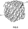
- FIG. 5 illustrates an example of a separator packing according to the first embodiment of the present invention.
- the separator packing may comprise a plurality of plates 51 that are disposed at an outlet of a associated bed (not represented on FIG. 5 ) so as to allow large drops (not represented on FIG. 5 ) coalesced at the bed to intercept the plates 51.
- the separator packing is made of an oleophilic material : this allows the intercepted large drops to adhere to the plates 51.
- the plates 51 have a substantially diagonal orientation that is adapted for guiding the adhered large drops upward.
- the adhered drops may, upon a flow of fluid, be guided along the plates upon a flow velocity, thus being guided upward. On the contrary, a continuous aqueous phase flows through the separator packing.
- FIG. 6 illustrates a first example of a system allows to separate an emulsion fluid into a recovered fluid and a purified fluid.
- the emulsion fluid comprises a continuous phase 65, a dispersed phase 67 and a coalesced portion 66.
- the purified fluid is essentially constituted of the continuous phase.
- the system comprises a bed 61 supporting a coalescing element 63.
- the coalescing element 63 allows to coalesce at least a portion of the dispersed phase 67 into large drops 69 that are detached from the coalescing element 63 upon a flow of the continuous phase.
- the system further comprises a weir 64 located along the bed 61 at an upstream side of the bed 61. The weir 64 allows to prevent the coalesced portion 66 to flow through the bed 61.
- the system comprises a vessel at an inlet of which the emulsion fluid flows into the vessel.
- the system may comprise further beds (not represented on FIG. 6 ) to improve the separating.
- the system may further comprise a recovery outlet 62, e.g. a recovery pipe, that allows to recover the coalesced portion 66.
- the recovery pipe is located at the upstream side of the bed 61. If the coalesced portion 66 enters into the bed 61, this has the effect of reducing the quality of the purified fluid.
- the weir 64 e.g. a metal sheet, allows to isolate the bed 61 from the coalesced portion 66.
- the system may achieve to produce a purified water having a given quality with a lower number of beds than a system from prior art, since the weir prevents a coalesced portion to flow along the vessel.
- a vessel system comprising a relatively low number of beds, i.e. with a vessel that has a relatively short length.
- the vessel system is hence easier to manipulate than the vessel systems from prior art.
- a vessel system with a coalescing element allows to separate small oil droplets from the aqueous phase.
- a vessel system according to the present invention may have a shorter length than a vessel system according to prior art and is hence easier to manipulate. Furthermore, the vessel system according to the present invention occupies less space on a boat.
- the coalesced portion 66 results from a pre-treatment of the emulsion fluid within the vessel 68.
- the pre-treatment allows to remove a high percentage of the dispersed phase.
- the pre-treatment may be relatively basic : for example, the emulsion fluid simply passes through a pre-treatment box 610 of the vessel 68. Most of the dispersed phase may move upward upon gravity at the pre-treatment box 610.
- the recovery outlet 62 allows to recover the coalesced portion 66.
- FIG. 7 illustrates a second example of a system, wherein emulsion fluid comprising a continuous phase 75, a dispersed phase (not represented on FIG. 7 ) and a coalesced portion 76 may flow through a bed 71b that supports a coalescing element 73b.
- the emulsion fluid itself results from an upstream portion of a vessel 78, the upstream portion of the vessel 78 comprising a distinct previous bed 71a.
- a coalescing action of a distinct coalescing element 73a supported by the distinct previous bed 71a produces large drops 79a.
- the large drops 79a move upward upon gravity.
- a weir 74b e.g. a metal sheet, is provided along the bed 71b.
- a recovery outlet 72 allows to remove the coalesced portion 66 while being retained by the weir 74b.
- the second example of vessel system comprises a plurality of beds (71a, 71b). Each bed may be associated to a weir (74a, 74b). Each bed allows to coalesce at least a portion of a dispersed phase of an upstream fluid into large drops (79a, 79b).
- the coalescing element is a Reusable Polymer Absorbent (RPA), i.e. polyurethane foam shredded in small flakes so as to increase a surface area offered to a flow.
- RPA Reusable Polymer Absorbent
- the vessel system according to the present invention comprises an output pipe that is located downstream of the beds.
- the output pipe may be oriented downward, so as to insure a prioritized collecting of the purified fluid.
- the first embodiment of the present invention is combined with either of the systems illustrated in Figures 6 and7.
- large drop we means any coalesced fluid having a size that is relatively larger than a size of droplets initially present in an emulsion fluid.
- the large drops may hence have a substantially spherical shape, a longitudinal shape etc.
- the large drops may also be a single layer that is detached from a bed, or is formed from substantially spherical drops.
Landscapes
- Physics & Mathematics (AREA)
- Thermal Sciences (AREA)
- Chemical & Material Sciences (AREA)
- Chemical Kinetics & Catalysis (AREA)
- Production Of Liquid Hydrocarbon Mixture For Refining Petroleum (AREA)
- Liquid Carbonaceous Fuels (AREA)
- Colloid Chemistry (AREA)
Description
- The invention relates generally to the separating of small droplets from a continuous phase of a water/hydrocarbons emulsion fluid with a coalescing element.
- Filtering a fluid comprising two non-miscible phases is a common operation. Typically the fluid may be stored in a container during a given time: a first phase and a second phase may separate upon gravity. The phase having the smallest density is then collected at a surface of the fluid.
- However, the fluid may be under a form of an emulsion comprising a continuous phase and a dispersed phase. The emulsion may be relatively stable, in particular if a surfactant is added at a forming of the emulsion.
- A separator packing allows to separate a dispersed oily phase from a continuous phase. The separator packing comprises a plurality of plates that are made of an oleophilic material so that drops of the dispersed oily phase adhere to the plates. The plates are oriented in a diagonal direction in such a way that the coalesced drops move upward along the plates upon a pressure generated by a flow of the continuous phase. The continuous phase flows through the separator packing. In case of a further phase that is solid, particles of the solid phase are intercepted by the separator packing and drop at the bottom of the separator under the effect of gravity. The separator packing hence guides the dispersed oily phase upward, the solid phase downward and let the continuous phase flow.
- However, if the dispersed phase is in a form of relatively small droplets, the effect of the gravity is minimized. It may hence take a relatively long time to separate an emulsion by storing it in a container. Under such circumstances, a separator packing provides a relatively low efficiency in separating small droplets from a continuous phase.
- British Patent
1 418 806 -
US Patent 5,239,040 to E.R.T. Environmental Research Technology K.S.P.W. Inc. (CA), published August 24, 1993, describes a polyurethane particulate liquid absorbent. The absorbent is prepared from specific reactants using a particular process. The absorbent is suitable for use in cleaning up liquids contaminated with oil droplets. The absorbent allows to intercept the oil droplets. The absorbent and the intercepted oil droplets may be separated by a centrifugation step, thus providing recovered oil, and oil-free absorbent for re-use. - International application
WO02/20115 US Patent 5,239,040 may be used.US 4 022 694 A also discloses an oil-water separator making use of a block of polyurethane foam as an absorbing/coalescing element. -
FIG. 1A, FIG. 1B and FIG. 1C illustrate a coalescing of the oil droplets at a RPA bed according to prior art. A flow of an emulsion comprising a watercontinuous phase 13 andoil droplets 12 passes throughRPA elements 11. As represented inFIG. 1A , theRPA elements 11 intercept oil droplets. Despite the intercepteddroplets 14 that adhere to theRPA elements 11, the emulsion may still comprisefree droplets 17 at an outlet of theRPA elements 11. - The intercepted
droplets 14 may, upon the flow of the emulsion, form alayer 16 at a surface of theRPA elements 11, as represented inFIG. 1B . - As the
layer 16 increases, the flow of the emulsion creates an increasing shearing force onto thelayer 16. Consequently,large oil drops 15 may form from thelayer 16 and be entrained by the flow as represented inFIG. 1C . - A creaming of an emulsion, i.e. a velocity of a given drop upon gravity is governed by Stoke's law : the large oil drops 16 move upward faster than the oil droplets (12, 17).
-
FIG. 2 illustrates a system for separating oil droplets from a continuous water phase according to prior art. A plurality of RPA beds (27a, 27b) are provided within avessel 28 through which an emulsion fluid comprising oil droplets (22a, 22b, 22c) among acontinuous water phase 23 may flow. - A first RPA bed 27a allows to form
large oil drops 25a from theoil droplets 22a. An number of non retainedoil droplets 22b may pass trough the first RPA bed 27a without adhering to any RPA element (not represented onFIG. 2 ) of the first RPA bed 27a. The large oil drops 25a move upward upon gravity faster than theoil droplets 22b. The large oil drops form at a surface of the water phase an oil layer 24. A recovery outlet, e.g. arecovery pipe 29 at the surface allows to recover the oil layer 24. - A similar process is iterated via a
second RPA bed 27b and further RPA beds (not represented onFIG. 2 ) for further cleaning if necessary. It is desirable to avoid thelarge oil drops 25a generated at the first RPA bed 27a to enter thesecond RPA bed 27b. The recovering of thelarge oil drops 25a depends on a plurality of parameters : a velocity of the flow of emulsion fluid, a density of oil, a density of water, a distance between the first RPA bed 27a and the second RPA be 27b, and a height between the large oil drop at thefirst RPA bed 25a and the oil layer 24. In order to insure an efficient separating of theoil droplets 22a from thecontinuous water phase 23, the RPA beds (27a, 27b) may be positioned at a relatively high distance. - The invention relates to a system for separating a water/hydrocarbons emulsion fluid into a recovered oil fluid and a purified water fluid according to claim 1. The emulsion fluid comprises a continuous phase and a dispersed phase. The purified water fluid is essentially constituted of the continuous phase. The system comprises a vessel at an inlet of which the emulsion fluid may flow. The system further comprises one or more coalescing element. Each coalescing element allows to coalesce at least a portion of the dispersed phase into large drops further detached from the coalescing element upon a flow of the emulsion fluid. The system further comprises one or more guiding means. Each guiding means is associated with one coalescing element to guide the detached large drops for further recovery.
- In a first preferred embodiment, the system further comprises one or more bed, each bed allowing to support one coalescing element. The system further comprises one or more recovery outlet. Each recovery outlet allows to recover the recovered fluid from large drops detached from one coalescing element.
- According to the invention, the guiding means is a separator packing. The separator packing has a structure that is adapted to allow the continuous phase to flow through the separator packing.
- In a second preferred embodiment, each separator packing is substantially located at 10 millimeters of the associated coalescing element so as to allow a burst of bubbles of the continuous phase. The bubbles are surrounded by a film of the dispersed phase. The bubbles are formed between the coalescing element and the separator packing.
- According to the invention, the separator packing comprises a plurality of plates disposed at an output of the at least one associated coalescing to intercept the large drops. The dispersed phase may comprise oil droplets. The plurality of plates are made of an oleophilic material so that the intercepted large drops adhere to the plates The plurality of plates have a diagonal orientation adapted for guiding the adhered large drops upward.
- In a third preferred embodiment, the emulsion fluid is a produced water associated with a production of hydrocarbons. According to the invention, the coalescing element is a Reusable Polymer Absorbent, being polyurethane foam shredded in small flakes so as to increase a surface area offered to a flow.
- In a second aspect, the invention provides a method for recovering from a water/hydrocarbons emulsion fluid a recovered fluid and a purified water fluid according to claim 6. The emulsion fluid comprises a continuous phase and a dispersed phase. The purified water fluid is essentially constituted of the continuous phase. The method comprises providing a flow of at least a portion of the emulsion fluid through at least one bed within a vessel. Each bed supports a coalescing element made of Reusable Polymer Absorbent material, being polyurethane foam shredded in small flakes so as to increase a surface area offered to a flow, whereby at least a portion of the dispersed phase coalesces into large drops. The coalesced large drops are detached from each bed by means of a flow velocity. The detached large drops are guided with at least one guiding means. The at least one guiding means is associated with the at least one bed. The method further comprises recovering the recovered fluid from the guided large drops.
- According to the second aspect of the invention, the method further comprises repeating the coalescing, the detaching, the guiding and the recovering at a further location of the vessel.
- In a fourth preferred embodiment, the dispersed phase comprises droplets of oil.
- According to another embodiment at least one bed supports a coalescing element. The coalescing element allows to coalesce at least a portion of the dispersed phase into large drops detached from the coalescing element upon a flow of the continuous phase. The system further comprises at least one weir located along the at least one bed at an upstream side of the at least one bed. Each weir allows to prevent the coalesced portion to flow through an associated bed.
- In another preferred embodiment, the system further comprises a recovery outlet located at the upstream side of the bed, the recovery outlet allowing to recover the coalesced portion.
- Other aspects and advantages of the invention will be apparent from the following description and the appended claims.
-
-
FIG. 1A, FIG. 1B and FIG. 1C illustrate a coalescing of the oil droplets at a RPA bed according to prior art. -
FIG. 2 illustrates a system for separating oil droplets from a continuous water phase according to prior art. -
FIG. 3 illustrates an example of a system according to a first embodiment of the present invention. -
FIG. 4A illustrates a formation of bubbles of water in an example of a system according to the first embodiment of the present invention. -
FIG. 4B and FIG. 4C illustrate a burst of bubbles of water in the example of the system illustrated inFIG. 4A . -
FIG. 5 illustrates an example of a separator packing according to the first embodiment of the present invention. -
FIG. 6 illustrates a first example of a system which can be combined with the embodiment of the present invention. -
FIG. 7 illustrates a second example of a system which can be combined with the embodiment of the present invention. - A vessel system according to prior art comprising a plurality of RPA beds - or any bed supporting coalescing element through which an emulsion may flow - allows to separate small droplets of the emulsion from a continuous phase. The coalescing element allows to generate large drops by coalescing the droplets. The large drops are detached from the coalescing element upon a flow of the emulsion. The large drops move to a surface of the continuous phase upon gravity and may be easily recovered. Each bed of coalescing element needs to be positioned at a relatively high distance from others beds so as to avoid the large drops generated at a determined bed to enter a further bed before being recovered.
- However, because of the relatively high distance between two coalescing elements, the vessel system may have a relatively long length.
- Such vessel system may for example be used in petroleum industry. The production of hydrocarbons is usually associated with the generation of a produced water. The produced water needs to be cleaned from oil before disposal. The vessel system allows to separate a last fraction of oil present in the water as an emulsion. In case of an offshore installation, the length of the vessel is a crucial factor as a vessel having a relatively short length is easier to accommodate.
- There is a need for a separating system allowing to separate small droplets from a continuous phase of an emulsion that has a relatively short length so as to allow an easier manipulating. Such a separating system may be used in the petroleum industry as well as in any other industry. Typically, many industries produce oily water as a byproduct.
-
FIG. 3 illustrates an example of a system according to the present invention. The system allows to separate a water/hydrocarbons emulsion fluid comprising a continuous phase and a dispersed phase into a recovered oil fluid and a purified water fluid. The purified water fluid is essentially constituted of the continuous phase. The system comprises avessel 38. Thevessel 38 comprises an inlet through which the emulsion fluid may flow so as to meet one ormore coalescing element 37a. Each coalescingelement 37a allows to coalesce at least a portion of the dispersed phase into large drops (not represented onFIG. 3 ). The coalesced large drops are detached from the coalescing element upon a flow of the emulsion fluid. The coalesced large drops are guided for further recovery by a guiding means 33a. - The guiding means, i.e. a
separator packing 33a allow to improve a recovering of the recovered fluid, i.e. of the large drops. - Droplets (not represented on
FIG. 3 ) of the dispersed phase may coalesce at the coalescing element and form the large drops. The large drops move to the surface of the fluid upon gravity, and reach the surface faster than the droplets. - Typically, the dispersed phase has a lower density than the continuous phase and the large oil drops hence move upward upon gravity. During the moving up, or at a reaching of an upper side of the vessel, the large drops may meet each other and form a layer (not represented).
- The system may comprise a recovery outlet, e.g. a recovery pipe 39a. The recovery pipe allows to recover at least a portion of the layer at surface.
- During the moving up, the large drops are deported along a deportation distance because of a flow velocity. The separator packing, as guiding the large drops upward, allows to reduce the deportation distance. It is hence possible to position a
further coalescing element 37b at a relatively low distance from the coalescingelement 37a. - The vessel according to the first embodiment of the present invention may hence achieve to produce a purified fluid having a same quality as those produced with vessels systems from prior art with a shorter length. The vessel of the present invention is easier to manipulate and may be used in various industries, e.g. an offshore oil/gas exploitation.
- In this latter case, the emulsion fluid is a produced water associated with a production of hydrocarbons. The produced water, at the flowing into the vessel may be already relatively clean: the produced water may contain a continuous water phase and oil droplets. The oil droplets have a relatively small diameter and are difficult to remove by traditional separating means. The vessel systems with coalescing elements, whether according to prior art or to the first embodiment of the present invention, allow to separate the oil droplets so as to produce a filtered fluid having a relatively low oil content, e.g. 15 ppm. The vessel systems of the present invention, are, for a given oil content, shorter than the vessel systems from prior art, which may be appreciated for example at a transportation of the vessel system to the offshore oil/gas exploitation.
- Typically, the vessel system according to the first embodiment of the present invention may comprise a plurality of beds (31a, 31b), a plurality of coalescing elements (37a, 37b), a plurality of separator packings (33a, 33b) within the
vessel 38 and a plurality of recovery pipes (39a, 39b) so as to allow to repeat the coalescing, the guiding and the recovering. - Each coalescing element may be supported by an associated bed. As represented on
FIG. 3 , afirst bed 31a supports the coalescingelement 37a and asecond bed 31b supports thefurther coalescing element 37b. - One recovery pipe may be provided for each bed (37a, 37b). Each recovery pipe (39a, 39b) allows to recover the recovered fluid from the large drops detached from one associated bed (37a, 37b).
- The
separator packing 33a ofFIG.3 guides the large drops coalesced at thefirst bed 31a for further recovery at a first recovery pipe 39a. Similarly, a second separator packing 33b guides the large drops coalesced at thesecond bed 31b for further recovery at a second recovery pipe 39b. Each separator packing (33a, 33b) is located downstream of one associated bed (37a, 37b). - The separator packings (33a, 33b) allow to avoid that the large drops flow into a further bed. With the vessels systems from prior art, there is an higher risk that a coalesced large drop enters the further bed. If some large drops enters the further bed, an efficiency of the vessel system to separate droplets from the continuous phase may be considerably reduced. Consequently, the vessels systems from prior art comprises an high number of beds so as to insure that a given dispersed phase content in the purified fluid is achieved. The vessels systems according to the present invention hence allow to provide a lower number of beds to achieve the given dispersed phase content in the purified fluid. Typically, in a case of produced water to be purified, a vessel system according to the present invention comprising eight beds produces a purified fluid having an oil content lower than 15 ppm, whereas in prior art, such oil content is provided with a vessel system comprising twelve beds.
- Preferably the dispersed phase of the emulsion fluid comprises droplets of oil. The continuous phase may be for example water, or brine.
- Preferably the separator packing is positioned at a certain distance, typically 10 millimeters, of the associated bed. It may happen that bubbles of water form at an output of the bed. The bubbles may, in the vessels systems from prior art, fill a space between two beds. The associated recovery pipe hence recovers bubbles instead of pure oil. The separator packing allows to avoid the recovering of the bubbles of water.
-
FIG. 4A illustrates a formation of bubbles of water in an example of a system according to the first embodiment of the present invention. Avessel 48 comprises abed 47 of coalescing material, e.g. RPA polymer. An emulsion fluid comprising a dispersed oil phase into oil droplets (not represented onFIG. 4A ) and a continuous water phase (not represented onFIG. 4A ) flows through thevessel 48. The RPA polymer allows to form large oil drops (not represented onFIG. 4A ) from the oil droplets. It may happen that bubbles ofwater 41 are surrounded by a film of oil formed at an outlet of thebed 47. In the vessel systems according to the invention, a separator packing 43 is located at a certain distance from thebed 47. -
FIG. 4B and FIG. 4C illustrate a burst of bubbles of water in the example of the system already illustrated inFIG. 4A . The bubbles ofwater 41 may expand and begin to fill a space between thebed 47 and the separator packing 43. When thebubbles 41 reach the separator packing 43, thebubbles 41 burst as illustrated inFIG. 4B . The bursting of thebubbles 41 generates a coalescing of the film of oil into oil drops 45. The oil drops 45 are guided by the separator packing 43. Therecovery pipe 49 allows to recover pure oil. -
FIG. 5 illustrates an example of a separator packing according to the first embodiment of the present invention. The separator packing may comprise a plurality ofplates 51 that are disposed at an outlet of a associated bed (not represented onFIG. 5 ) so as to allow large drops (not represented onFIG. 5 ) coalesced at the bed to intercept theplates 51. If the large drops are made of oil, the separator packing is made of an oleophilic material : this allows the intercepted large drops to adhere to theplates 51. Theplates 51 have a substantially diagonal orientation that is adapted for guiding the adhered large drops upward. The adhered drops may, upon a flow of fluid, be guided along the plates upon a flow velocity, thus being guided upward. On the contrary, a continuous aqueous phase flows through the separator packing. -
FIG. 6 illustrates a first example of a system allows to separate an emulsion fluid into a recovered fluid and a purified fluid. The emulsion fluid comprises acontinuous phase 65, a dispersedphase 67 and a coalescedportion 66. The purified fluid is essentially constituted of the continuous phase. - The system comprises a bed 61 supporting a coalescing element 63. The coalescing element 63 allows to coalesce at least a portion of the dispersed
phase 67 intolarge drops 69 that are detached from the coalescing element 63 upon a flow of the continuous phase. The system further comprises aweir 64 located along the bed 61 at an upstream side of the bed 61. Theweir 64 allows to prevent the coalescedportion 66 to flow through the bed 61. - Preferably the system comprises a vessel at an inlet of which the emulsion fluid flows into the vessel. The system may comprise further beds (not represented on
FIG. 6 ) to improve the separating. - The system may further comprise a
recovery outlet 62, e.g. a recovery pipe, that allows to recover the coalescedportion 66. The recovery pipe is located at the upstream side of the bed 61. If the coalescedportion 66 enters into the bed 61, this has the effect of reducing the quality of the purified fluid. Theweir 64, e.g. a metal sheet, allows to isolate the bed 61 from the coalescedportion 66. - The system may achieve to produce a purified water having a given quality with a lower number of beds than a system from prior art, since the weir prevents a coalesced portion to flow along the vessel. Hence it allows to provide a separating with a vessel system comprising a relatively low number of beds, i.e. with a vessel that has a relatively short length. The vessel system is hence easier to manipulate than the vessel systems from prior art.
- This may be particularly useful in a case of an offshore hydrocarbon exploitation. The production of the hydrocarbon is associated with produced water, i.e. a mixture of an aqueous phase and an oily phase. The mixture needs to be purified for further disposal. Most of the oily phase may be removed with traditional separating techniques. A vessel system with a coalescing element allows to separate small oil droplets from the aqueous phase. A vessel system according to the present invention may have a shorter length than a vessel system according to prior art and is hence easier to manipulate. Furthermore, the vessel system according to the present invention occupies less space on a boat.
- In the first example of system illustrated in
FIG. 6 , the coalescedportion 66 results from a pre-treatment of the emulsion fluid within thevessel 68. The pre-treatment allows to remove a high percentage of the dispersed phase. The pre-treatment may be relatively basic : for example, the emulsion fluid simply passes through apre-treatment box 610 of thevessel 68. Most of the dispersed phase may move upward upon gravity at thepre-treatment box 610. Therecovery outlet 62 allows to recover the coalescedportion 66. -
FIG. 7 illustrates a second example of a system, wherein emulsion fluid comprising acontinuous phase 75, a dispersed phase (not represented onFIG. 7 ) and a coalescedportion 76 may flow through abed 71b that supports a coalescingelement 73b. The emulsion fluid itself results from an upstream portion of avessel 78, the upstream portion of thevessel 78 comprising a distinctprevious bed 71a. A coalescing action of adistinct coalescing element 73a supported by the distinctprevious bed 71a produceslarge drops 79a. The large drops 79a move upward upon gravity. In order to avoid that the coalescedportion 66 enters into thebed 71b, aweir 74b, e.g. a metal sheet, is provided along thebed 71b. Arecovery outlet 72 allows to remove the coalescedportion 66 while being retained by theweir 74b. - The second example of vessel system comprises a plurality of beds (71a, 71b). Each bed may be associated to a weir (74a, 74b). Each bed allows to coalesce at least a portion of a dispersed phase of an upstream fluid into large drops (79a, 79b).
- The coalescing element is a Reusable Polymer Absorbent (RPA), i.e. polyurethane foam shredded in small flakes so as to increase a surface area offered to a flow.
- Preferably the vessel system according to the present invention comprises an output pipe that is located downstream of the beds. The output pipe may be oriented downward, so as to insure a prioritized collecting of the purified fluid.
- Preferably, the first embodiment of the present invention is combined with either of the systems illustrated in
Figures 6 and7. - By "large drop", we means any coalesced fluid having a size that is relatively larger than a size of droplets initially present in an emulsion fluid. The large drops may hence have a substantially spherical shape, a longitudinal shape etc. The large drops may also be a single layer that is detached from a bed, or is formed from substantially spherical drops.
Claims (7)
- A system for separating a water/hydrocarbon emulsion fluid into a recovered hydrocarbon fluid and a purified water fluid, the water/hydrocarbon emulsion fluid comprising a continuous phase and a dispersed phase, the purified water fluid being essentially constituted of the continuous phase, the system comprising:a vessel (38, 48) at an inlet of which the water/hydrocarbon emulsion fluid may flow;one or more coalescing element (37a, 37b) made of Reusable Polymer Absorbent material, being polyurethane foam shredded in small flakes so as to increase a surface area offered to a flow; each coalescing element allowing to coalesce at least a portion of the dispersed phase into large drops, said large drops being further detached from the coalescing element upon a flow of the emulsion fluid;one or more guiding means (33a, 33b, 43), wherein the guiding means is a separator packing, the separator packing having a structure that is adapted to allow the continuous phase to flow through the separator packing, each guiding means being associated with one coalescing element to guide the said detached large drops for further recovery and wherein the separator packing comprises a plurality of plates (51) to intercept said detached large drops; wherein:the plurality of plates (51) are made of an oleophilic material so that the intercepted large drops adhere to the plates;the plurality of plates (51) have a diagonal orientation adapted for guiding the adhered large drops upward.
- The system of claim 1, further comprising :one or more beds (31a, 31b), each bed allowing to support one coalescing element (37a, 37b) made of Reusable Polymer Absorbent material, being polyurethane foam shredded in small flakes so as to increase a surface area offered to a flow;one or more recovery outlets (39a, 39b), each recovery outlet allowing to recover the recovered fluid from large drops detached from one coalescing element (37a, 37b).
- The system according to claim 1 or 2, wherein
each guiding means is substantially located at 10 millimeters of the associated coalescing element so as to allow a burst of bubbles (41) of the continuous phase, the bubbles being surrounded by a film of the dispersed phase, and the bubbles being formed between the coalescing element and the guiding means. - The system according to any one of claims 1 to 3, comprising at least two coalescing elements and further comprising one or more weirs (74a, 74b), each weir being associated with one coalescing element, said weir being located along and at an upstream side of the associated coalescing element, and said weir allowing to prevent the detached large drops of an upstream coalescing element to flow through the associated coalescing element.
- The system of claim 4, wherein each weir is located at an upper portion of the vessel.
- A method for separating from a water/hydrocarbon emulsion fluid into a recovered hydrocarbon fluid and a purified water fluid, the water/hydrocarbon emulsion fluid comprising a continuous phase and a dispersed phase, the purified water fluid being essentially constituted of the continuous phase, the method comprising:providing a flow of at least a portion of the water/hydrocarbon emulsion fluid through at least one bed (31a, 31b) within a vessel (38, 48), each bed supporting a coalescing element (37a, 37b) made of Reusable Polymer Absorbent material, being polyurethane foam shredded in small flakes so as to increase a surface area offered to a flow;whereby at least a portion of the dispersed phase coalesces into large drops;detaching said large drops from each bed (31a, 31b) by means of a flow velocity;guiding the detached large drops with at least one guiding means (33a, 33b, 43), wherein the guiding means is a separator packing, the separator packing having a structure that is adapted to allow the continuous phase to flow through the separator packing, the at least one guiding means being associated with the at least one bed (31a, 31b),; and wherein the separator packing comprises a plurality of plates (51) to intercept said detached large drops; wherein:
the plurality of plates (51) are made of an oleophilic material so that the intercepted large drops adhere to the plates;the plurality of plates (51) have a diagonal orientation adapted for guiding the adhered large drops upward;intercepting the detached large drops with the plates (51) of the separator packing, the large drops adhering onto the plates;guiding the adhered large drops along the plates (51) upon a flow velocity recovering the recovered oil fluid from the guided large drops; andrecovering the purified water fluid from the continuous phase. - The method of claim 6, further comprising: repeating the coalescing, the detaching, the guiding and the recovering at a further location of the vessel (38, 48).
Priority Applications (7)
| Application Number | Priority Date | Filing Date | Title |
|---|---|---|---|
| EP04290203.1A EP1559465B1 (en) | 2004-01-27 | 2004-01-27 | Small droplets recovery system |
| EA200601379A EA012976B1 (en) | 2004-01-27 | 2005-01-10 | A system for separating aqueous/hydrogen emulsion fluid and a method for recovery thereof and purified aqueous/hydrogen fluid |
| BRPI0507095-3A BRPI0507095B1 (en) | 2004-01-27 | 2005-01-10 | SYSTEM FOR SEPARATING A WATER / HYDROCARIO EMULSION FLUID IN THE FORM OF A RECOVERED OIL FLUID AND A PURIFIED WATER FLUID, AND METHOD FOR RECOVERING FROM A WATER / HYDROCAROID FLUID EYE / HYDROCARBUID FLUID |
| CA2553219A CA2553219C (en) | 2004-01-27 | 2005-01-10 | Small droplets recovery system |
| PCT/EP2005/000227 WO2005070514A1 (en) | 2004-01-27 | 2005-01-10 | Small droplets recovery system |
| US10/597,124 US7678286B2 (en) | 2004-01-27 | 2005-01-10 | Small droplets recovery system |
| NO20063520A NO343608B1 (en) | 2004-01-27 | 2006-08-02 | System and method for separating a water / hydrocarbon emulsion fluid. |
Applications Claiming Priority (1)
| Application Number | Priority Date | Filing Date | Title |
|---|---|---|---|
| EP04290203.1A EP1559465B1 (en) | 2004-01-27 | 2004-01-27 | Small droplets recovery system |
Publications (2)
| Publication Number | Publication Date |
|---|---|
| EP1559465A1 EP1559465A1 (en) | 2005-08-03 |
| EP1559465B1 true EP1559465B1 (en) | 2019-03-27 |
Family
ID=34639479
Family Applications (1)
| Application Number | Title | Priority Date | Filing Date |
|---|---|---|---|
| EP04290203.1A Expired - Lifetime EP1559465B1 (en) | 2004-01-27 | 2004-01-27 | Small droplets recovery system |
Country Status (7)
| Country | Link |
|---|---|
| US (1) | US7678286B2 (en) |
| EP (1) | EP1559465B1 (en) |
| BR (1) | BRPI0507095B1 (en) |
| CA (1) | CA2553219C (en) |
| EA (1) | EA012976B1 (en) |
| NO (1) | NO343608B1 (en) |
| WO (1) | WO2005070514A1 (en) |
Families Citing this family (4)
| Publication number | Priority date | Publication date | Assignee | Title |
|---|---|---|---|---|
| GB0022013D0 (en) * | 2000-09-07 | 2000-10-25 | Earth Canada Corp | Polyurethane oil de-emulsification unit |
| EP2226106B1 (en) * | 2009-02-20 | 2015-09-02 | FRÄNKISCHE ROHRWERKE GEBR. KIRCHNER GmbH & Co KG | Light fluid separation device |
| RU2469766C1 (en) * | 2011-06-07 | 2012-12-20 | Открытое акционерное общество "Татнефть" имени В.Д. Шашина | Settling tank for purification of oil-containing wastewater |
| US9624454B2 (en) * | 2014-09-25 | 2017-04-18 | Biosynthetic Technologies, Llc | Reclamation of estolide base oils from compositions comprising immiscible components |
Family Cites Families (17)
| Publication number | Priority date | Publication date | Assignee | Title |
|---|---|---|---|---|
| US2405838A (en) * | 1944-03-01 | 1946-08-13 | Lawson Archibald | Liquid separator apparatus |
| US2731150A (en) * | 1952-05-26 | 1956-01-17 | Warner Lewis Company | Horizontal filter apparatus |
| US3231091A (en) * | 1962-10-29 | 1966-01-25 | Pfaudler Permutit Inc | Separator |
| BE793060A (en) * | 1971-12-24 | 1973-04-16 | Metallgesellschaft Ag | DEVICE FOR SEPARATING LIQUIDS |
| BE794932A (en) * | 1972-03-17 | 1973-05-29 | Continental Oil Co | PROCESS FOR CAUSING THE COALESCENCE OF DISPERSIONS OF WATER AND OLEOPHILIC LIQUIDS |
| US3957656A (en) * | 1972-04-28 | 1976-05-18 | Castelli Joseph L | Plate separator for fluid mixtures |
| US4022694A (en) * | 1974-05-06 | 1977-05-10 | Hydronautics, Incorporated | Oil-water separation apparatus |
| US4123365A (en) * | 1974-08-14 | 1978-10-31 | Ballast-Nedam Groep N.V. | Oil-water separator |
| US4278545A (en) * | 1979-09-12 | 1981-07-14 | The Bendix Corporation | Apparatus for separating solids and liquid components |
| DE3151749A1 (en) * | 1981-12-29 | 1983-07-14 | Central'noe proektno-konstruktorskoe i technologičeskoe bjuro Vsesojuznogo rybopromyšlennogo ob"edinenija azovo-černomorskogo bassejna | Crude oil/water separator |
| FR2552071B1 (en) * | 1983-09-21 | 1988-04-08 | Inst Nat Sciences Appliq | DEVICE FOR SEPARATING A PHASE DISPERSE IN EMULSION OR SUSPENSION IN A CONTINUOUS PHASE |
| DE4212449A1 (en) * | 1992-04-14 | 1993-10-28 | Dyckerhoff & Widmann Ag | Device for separating suspended substances from a liquid |
| US5531890A (en) * | 1993-05-28 | 1996-07-02 | Atlantic Richfield Company | Oil separation and disposal systems |
| DE4434271C2 (en) * | 1994-09-24 | 1996-11-28 | Buderus Guss Gmbh | Stackable coalescence element for insertion in a light liquid separator |
| DE29616832U1 (en) * | 1996-09-27 | 1996-12-19 | Buderus Guss Gmbh | Light liquid separator |
| US5762810A (en) * | 1996-11-22 | 1998-06-09 | Pelton; Paul | Coalescing oil/water separator |
| GB0022013D0 (en) * | 2000-09-07 | 2000-10-25 | Earth Canada Corp | Polyurethane oil de-emulsification unit |
-
2004
- 2004-01-27 EP EP04290203.1A patent/EP1559465B1/en not_active Expired - Lifetime
-
2005
- 2005-01-10 WO PCT/EP2005/000227 patent/WO2005070514A1/en active Application Filing
- 2005-01-10 BR BRPI0507095-3A patent/BRPI0507095B1/en active IP Right Grant
- 2005-01-10 CA CA2553219A patent/CA2553219C/en not_active Expired - Fee Related
- 2005-01-10 EA EA200601379A patent/EA012976B1/en not_active IP Right Cessation
- 2005-01-10 US US10/597,124 patent/US7678286B2/en not_active Expired - Fee Related
-
2006
- 2006-08-02 NO NO20063520A patent/NO343608B1/en unknown
Non-Patent Citations (1)
| Title |
|---|
| None * |
Also Published As
| Publication number | Publication date |
|---|---|
| NO20063520L (en) | 2006-10-24 |
| BRPI0507095B1 (en) | 2014-12-16 |
| EP1559465A1 (en) | 2005-08-03 |
| EA200601379A1 (en) | 2006-12-29 |
| EA012976B1 (en) | 2010-02-26 |
| WO2005070514A1 (en) | 2005-08-04 |
| CA2553219A1 (en) | 2005-08-04 |
| CA2553219C (en) | 2011-11-22 |
| NO343608B1 (en) | 2019-04-15 |
| US7678286B2 (en) | 2010-03-16 |
| WO2005070514B1 (en) | 2006-01-12 |
| BRPI0507095A (en) | 2007-06-19 |
| US20070039892A1 (en) | 2007-02-22 |
Similar Documents
| Publication | Publication Date | Title |
|---|---|---|
| KR101217363B1 (en) | A method and device for converting horizontal tanks into gas flotation separators | |
| US5656173A (en) | Method of removing dispersed oil from an oil in water emulsion employing aerated solutions within a coalescing media | |
| EP1284800B1 (en) | A method and a system for separating a mixture | |
| US3844743A (en) | Dispersed oil separator | |
| US3948767A (en) | Method and apparatus for separating oil from aqueous liquids | |
| EP3138617B1 (en) | Separator | |
| KR100559350B1 (en) | Method for the separation of a first liquid from a second one | |
| US4198300A (en) | Apparatus for removing suspended oil droplets from water | |
| US5543043A (en) | Clarification of produced water in the oil and gas industry | |
| CA2553219C (en) | Small droplets recovery system | |
| US6602423B2 (en) | Method and apparatus for removing foaming contaminants from hydrocarbon processing solvents | |
| US7160450B2 (en) | Method for removing oil, fat and grease from water | |
| US20100126925A1 (en) | Flotation device | |
| MXPA06008230A (en) | Small droplets recovery system | |
| Portnov et al. | Separator on the principle of gravitational-dynamic separation of emulsions (water–oil type) for solving various problems of oil and gas production, petrochemistry, and ecology | |
| WO1986003252A1 (en) | Three phase separator | |
| WO2006101399A1 (en) | Method for separation and a separator device | |
| Mulyandasari | Separator vessel selection and sizing (engineering design guideline) | |
| GB2189161A (en) | Separators | |
| White et al. | Best practices and technologies for enhancing produced water quality | |
| RU2105583C1 (en) | Method for dewatering of hydrocarbon media | |
| Parker et al. | A technical review of the principles of oil-water separation | |
| Ibrahim | CFD simulation coalescing plate to sepetaing water and oil in water treatment plant in petrolum project | |
| Kenawy et al. | A challenge to meet Environmental Law number-4, a comparative evaluation between water-treating modified systems and other available oil-water separation techniques | |
| Kolmetz | COALESCER SYSTEMS SELECTION, SIZING AND TROUBLESHOOING |
Legal Events
| Date | Code | Title | Description |
|---|---|---|---|
| PUAI | Public reference made under article 153(3) epc to a published international application that has entered the european phase |
Free format text: ORIGINAL CODE: 0009012 |
|
| AK | Designated contracting states |
Kind code of ref document: A1 Designated state(s): AT BE BG CH CY CZ DE DK EE ES FI FR GB GR HU IE IT LI LU MC NL PT RO SE SI SK TR |
|
| AX | Request for extension of the european patent |
Extension state: AL LT LV MK |
|
| 17P | Request for examination filed |
Effective date: 20060131 |
|
| AKX | Designation fees paid |
Designated state(s): AT BE BG CH CY CZ DE DK EE ES FI FR GB GR HU IE IT LI LU MC NL PT RO SE SI SK TR |
|
| RAP1 | Party data changed (applicant data changed or rights of an application transferred) |
Owner name: SCHLUMBERGER TECHNOLOGY B.V. Owner name: SCHLUMBERGER HOLDINGS LIMITED Owner name: SERVICES PETROLIERS SCHLUMBERGER |
|
| RAP1 | Party data changed (applicant data changed or rights of an application transferred) |
Owner name: SCHLUMBERGER HOLDINGS LIMITED Owner name: SCHLUMBERGER TECHNOLOGY B.V. Owner name: SERVICES PETROLIERS SCHLUMBERGER |
|
| 17Q | First examination report despatched |
Effective date: 20120502 |
|
| STAA | Information on the status of an ep patent application or granted ep patent |
Free format text: STATUS: EXAMINATION IS IN PROGRESS |
|
| GRAP | Despatch of communication of intention to grant a patent |
Free format text: ORIGINAL CODE: EPIDOSNIGR1 |
|
| STAA | Information on the status of an ep patent application or granted ep patent |
Free format text: STATUS: GRANT OF PATENT IS INTENDED |
|
| INTG | Intention to grant announced |
Effective date: 20181017 |
|
| RIC1 | Information provided on ipc code assigned before grant |
Ipc: B01D 17/02 20060101AFI20040707BHEP Ipc: B01D 17/04 20060101ALI20040707BHEP |
|
| GRAS | Grant fee paid |
Free format text: ORIGINAL CODE: EPIDOSNIGR3 |
|
| GRAA | (expected) grant |
Free format text: ORIGINAL CODE: 0009210 |
|
| STAA | Information on the status of an ep patent application or granted ep patent |
Free format text: STATUS: THE PATENT HAS BEEN GRANTED |
|
| REG | Reference to a national code |
Ref country code: DE Ref legal event code: R081 Ref document number: 602004053817 Country of ref document: DE Owner name: SCHLUMBERGER TECHNOLOGY B.V., NL Free format text: FORMER OWNERS: SCHLUMBERGER HOLDINGS LTD., ROAD TOWN, TORTOLA, VG; SERVICES PETROLIERS SCHLUMBERGER, PARIS, FR; SCHLUMBERGER TECHNOLOGY B.V., DEN HAAG/ THE HAGUE, NL |
|
| AK | Designated contracting states |
Kind code of ref document: B1 Designated state(s): AT BE BG CH CY CZ DE DK EE ES FI FR GB GR HU IE IT LI LU MC NL PT RO SE SI SK TR |
|
| REG | Reference to a national code |
Ref country code: GB Ref legal event code: FG4D |
|
| REG | Reference to a national code |
Ref country code: CH Ref legal event code: EP |
|
| REG | Reference to a national code |
Ref country code: DE Ref legal event code: R096 Ref document number: 602004053817 Country of ref document: DE |
|
| REG | Reference to a national code |
Ref country code: AT Ref legal event code: REF Ref document number: 1112356 Country of ref document: AT Kind code of ref document: T Effective date: 20190415 |
|
| REG | Reference to a national code |
Ref country code: IE Ref legal event code: FG4D |
|
| PG25 | Lapsed in a contracting state [announced via postgrant information from national office to epo] |
Ref country code: FI Free format text: LAPSE BECAUSE OF FAILURE TO SUBMIT A TRANSLATION OF THE DESCRIPTION OR TO PAY THE FEE WITHIN THE PRESCRIBED TIME-LIMIT Effective date: 20190327 Ref country code: SE Free format text: LAPSE BECAUSE OF FAILURE TO SUBMIT A TRANSLATION OF THE DESCRIPTION OR TO PAY THE FEE WITHIN THE PRESCRIBED TIME-LIMIT Effective date: 20190327 |
|
| REG | Reference to a national code |
Ref country code: NL Ref legal event code: MP Effective date: 20190327 |
|
| PG25 | Lapsed in a contracting state [announced via postgrant information from national office to epo] |
Ref country code: NL Free format text: LAPSE BECAUSE OF FAILURE TO SUBMIT A TRANSLATION OF THE DESCRIPTION OR TO PAY THE FEE WITHIN THE PRESCRIBED TIME-LIMIT Effective date: 20190327 Ref country code: BG Free format text: LAPSE BECAUSE OF FAILURE TO SUBMIT A TRANSLATION OF THE DESCRIPTION OR TO PAY THE FEE WITHIN THE PRESCRIBED TIME-LIMIT Effective date: 20190627 Ref country code: GR Free format text: LAPSE BECAUSE OF FAILURE TO SUBMIT A TRANSLATION OF THE DESCRIPTION OR TO PAY THE FEE WITHIN THE PRESCRIBED TIME-LIMIT Effective date: 20190628 |
|
| REG | Reference to a national code |
Ref country code: AT Ref legal event code: MK05 Ref document number: 1112356 Country of ref document: AT Kind code of ref document: T Effective date: 20190327 |
|
| PG25 | Lapsed in a contracting state [announced via postgrant information from national office to epo] |
Ref country code: EE Free format text: LAPSE BECAUSE OF FAILURE TO SUBMIT A TRANSLATION OF THE DESCRIPTION OR TO PAY THE FEE WITHIN THE PRESCRIBED TIME-LIMIT Effective date: 20190327 Ref country code: PT Free format text: LAPSE BECAUSE OF FAILURE TO SUBMIT A TRANSLATION OF THE DESCRIPTION OR TO PAY THE FEE WITHIN THE PRESCRIBED TIME-LIMIT Effective date: 20190727 Ref country code: SK Free format text: LAPSE BECAUSE OF FAILURE TO SUBMIT A TRANSLATION OF THE DESCRIPTION OR TO PAY THE FEE WITHIN THE PRESCRIBED TIME-LIMIT Effective date: 20190327 Ref country code: IT Free format text: LAPSE BECAUSE OF FAILURE TO SUBMIT A TRANSLATION OF THE DESCRIPTION OR TO PAY THE FEE WITHIN THE PRESCRIBED TIME-LIMIT Effective date: 20190327 Ref country code: ES Free format text: LAPSE BECAUSE OF FAILURE TO SUBMIT A TRANSLATION OF THE DESCRIPTION OR TO PAY THE FEE WITHIN THE PRESCRIBED TIME-LIMIT Effective date: 20190327 Ref country code: RO Free format text: LAPSE BECAUSE OF FAILURE TO SUBMIT A TRANSLATION OF THE DESCRIPTION OR TO PAY THE FEE WITHIN THE PRESCRIBED TIME-LIMIT Effective date: 20190327 Ref country code: CZ Free format text: LAPSE BECAUSE OF FAILURE TO SUBMIT A TRANSLATION OF THE DESCRIPTION OR TO PAY THE FEE WITHIN THE PRESCRIBED TIME-LIMIT Effective date: 20190327 |
|
| PG25 | Lapsed in a contracting state [announced via postgrant information from national office to epo] |
Ref country code: AT Free format text: LAPSE BECAUSE OF FAILURE TO SUBMIT A TRANSLATION OF THE DESCRIPTION OR TO PAY THE FEE WITHIN THE PRESCRIBED TIME-LIMIT Effective date: 20190327 |
|
| REG | Reference to a national code |
Ref country code: DE Ref legal event code: R097 Ref document number: 602004053817 Country of ref document: DE |
|
| PG25 | Lapsed in a contracting state [announced via postgrant information from national office to epo] |
Ref country code: DK Free format text: LAPSE BECAUSE OF FAILURE TO SUBMIT A TRANSLATION OF THE DESCRIPTION OR TO PAY THE FEE WITHIN THE PRESCRIBED TIME-LIMIT Effective date: 20190327 |
|
| PLBE | No opposition filed within time limit |
Free format text: ORIGINAL CODE: 0009261 |
|
| STAA | Information on the status of an ep patent application or granted ep patent |
Free format text: STATUS: NO OPPOSITION FILED WITHIN TIME LIMIT |
|
| PG25 | Lapsed in a contracting state [announced via postgrant information from national office to epo] |
Ref country code: SI Free format text: LAPSE BECAUSE OF FAILURE TO SUBMIT A TRANSLATION OF THE DESCRIPTION OR TO PAY THE FEE WITHIN THE PRESCRIBED TIME-LIMIT Effective date: 20190327 |
|
| 26N | No opposition filed |
Effective date: 20200103 |
|
| PG25 | Lapsed in a contracting state [announced via postgrant information from national office to epo] |
Ref country code: TR Free format text: LAPSE BECAUSE OF FAILURE TO SUBMIT A TRANSLATION OF THE DESCRIPTION OR TO PAY THE FEE WITHIN THE PRESCRIBED TIME-LIMIT Effective date: 20190327 |
|
| REG | Reference to a national code |
Ref country code: DE Ref legal event code: R119 Ref document number: 602004053817 Country of ref document: DE |
|
| PG25 | Lapsed in a contracting state [announced via postgrant information from national office to epo] |
Ref country code: MC Free format text: LAPSE BECAUSE OF FAILURE TO SUBMIT A TRANSLATION OF THE DESCRIPTION OR TO PAY THE FEE WITHIN THE PRESCRIBED TIME-LIMIT Effective date: 20190327 |
|
| REG | Reference to a national code |
Ref country code: CH Ref legal event code: PL |
|
| GBPC | Gb: european patent ceased through non-payment of renewal fee |
Effective date: 20200127 |
|
| REG | Reference to a national code |
Ref country code: BE Ref legal event code: MM Effective date: 20200131 |
|
| PG25 | Lapsed in a contracting state [announced via postgrant information from national office to epo] |
Ref country code: FR Free format text: LAPSE BECAUSE OF NON-PAYMENT OF DUE FEES Effective date: 20200131 Ref country code: GB Free format text: LAPSE BECAUSE OF NON-PAYMENT OF DUE FEES Effective date: 20200127 Ref country code: DE Free format text: LAPSE BECAUSE OF NON-PAYMENT OF DUE FEES Effective date: 20200801 Ref country code: LU Free format text: LAPSE BECAUSE OF NON-PAYMENT OF DUE FEES Effective date: 20200127 |
|
| PG25 | Lapsed in a contracting state [announced via postgrant information from national office to epo] |
Ref country code: LI Free format text: LAPSE BECAUSE OF NON-PAYMENT OF DUE FEES Effective date: 20200131 Ref country code: BE Free format text: LAPSE BECAUSE OF NON-PAYMENT OF DUE FEES Effective date: 20200131 Ref country code: CH Free format text: LAPSE BECAUSE OF NON-PAYMENT OF DUE FEES Effective date: 20200131 |
|
| PG25 | Lapsed in a contracting state [announced via postgrant information from national office to epo] |
Ref country code: IE Free format text: LAPSE BECAUSE OF NON-PAYMENT OF DUE FEES Effective date: 20200127 |
|
| PG25 | Lapsed in a contracting state [announced via postgrant information from national office to epo] |
Ref country code: CY Free format text: LAPSE BECAUSE OF FAILURE TO SUBMIT A TRANSLATION OF THE DESCRIPTION OR TO PAY THE FEE WITHIN THE PRESCRIBED TIME-LIMIT Effective date: 20190327 |
|
| P01 | Opt-out of the competence of the unified patent court (upc) registered |
Effective date: 20231208 |