EP2396828B1 - Solar energy collection apparatus - Google Patents
Solar energy collection apparatus Download PDFInfo
- Publication number
- EP2396828B1 EP2396828B1 EP10705429.8A EP10705429A EP2396828B1 EP 2396828 B1 EP2396828 B1 EP 2396828B1 EP 10705429 A EP10705429 A EP 10705429A EP 2396828 B1 EP2396828 B1 EP 2396828B1
- Authority
- EP
- European Patent Office
- Prior art keywords
- components
- solar energy
- collection apparatus
- energy collection
- cells
- Prior art date
- Legal status (The legal status is an assumption and is not a legal conclusion. Google has not performed a legal analysis and makes no representation as to the accuracy of the status listed.)
- Active
Links
- 230000015572 biosynthetic process Effects 0.000 claims description 59
- 238000005755 formation reaction Methods 0.000 claims description 59
- XLYOFNOQVPJJNP-UHFFFAOYSA-N water Substances O XLYOFNOQVPJJNP-UHFFFAOYSA-N 0.000 claims description 17
- 239000006096 absorbing agent Substances 0.000 claims description 16
- 238000005253 cladding Methods 0.000 claims description 15
- 239000004020 conductor Substances 0.000 claims description 6
- 229920001971 elastomer Polymers 0.000 claims description 5
- 239000000806 elastomer Substances 0.000 claims description 5
- 238000009413 insulation Methods 0.000 claims description 2
- 239000004411 aluminium Substances 0.000 description 8
- 229910052782 aluminium Inorganic materials 0.000 description 8
- XAGFODPZIPBFFR-UHFFFAOYSA-N aluminium Chemical compound [Al] XAGFODPZIPBFFR-UHFFFAOYSA-N 0.000 description 8
- 230000005611 electricity Effects 0.000 description 7
- 239000000463 material Substances 0.000 description 6
- 239000000853 adhesive Substances 0.000 description 4
- 230000001070 adhesive effect Effects 0.000 description 4
- 238000001125 extrusion Methods 0.000 description 4
- 238000005452 bending Methods 0.000 description 3
- 238000010438 heat treatment Methods 0.000 description 3
- RYGMFSIKBFXOCR-UHFFFAOYSA-N Copper Chemical compound [Cu] RYGMFSIKBFXOCR-UHFFFAOYSA-N 0.000 description 2
- 230000005540 biological transmission Effects 0.000 description 2
- 229910052802 copper Inorganic materials 0.000 description 2
- 239000010949 copper Substances 0.000 description 2
- 230000007423 decrease Effects 0.000 description 2
- 230000001419 dependent effect Effects 0.000 description 2
- 230000009977 dual effect Effects 0.000 description 2
- 238000004519 manufacturing process Methods 0.000 description 2
- 229910052751 metal Inorganic materials 0.000 description 2
- 239000002184 metal Substances 0.000 description 2
- 238000007789 sealing Methods 0.000 description 2
- 230000009182 swimming Effects 0.000 description 2
- 239000004793 Polystyrene Substances 0.000 description 1
- 229910000639 Spring steel Inorganic materials 0.000 description 1
- NIXOWILDQLNWCW-UHFFFAOYSA-N acrylic acid group Chemical group C(C=C)(=O)O NIXOWILDQLNWCW-UHFFFAOYSA-N 0.000 description 1
- 239000011449 brick Substances 0.000 description 1
- 238000010276 construction Methods 0.000 description 1
- 238000001816 cooling Methods 0.000 description 1
- 239000000498 cooling water Substances 0.000 description 1
- 238000010348 incorporation Methods 0.000 description 1
- 238000009434 installation Methods 0.000 description 1
- 239000011810 insulating material Substances 0.000 description 1
- 229920002223 polystyrene Polymers 0.000 description 1
- 229920002620 polyvinyl fluoride Polymers 0.000 description 1
Images


Classifications
-
- F—MECHANICAL ENGINEERING; LIGHTING; HEATING; WEAPONS; BLASTING
- F24—HEATING; RANGES; VENTILATING
- F24S—SOLAR HEAT COLLECTORS; SOLAR HEAT SYSTEMS
- F24S10/00—Solar heat collectors using working fluids
- F24S10/70—Solar heat collectors using working fluids the working fluids being conveyed through tubular absorbing conduits
- F24S10/75—Solar heat collectors using working fluids the working fluids being conveyed through tubular absorbing conduits with enlarged surfaces, e.g. with protrusions or corrugations
- F24S10/753—Solar heat collectors using working fluids the working fluids being conveyed through tubular absorbing conduits with enlarged surfaces, e.g. with protrusions or corrugations the conduits being parallel to each other
-
- F—MECHANICAL ENGINEERING; LIGHTING; HEATING; WEAPONS; BLASTING
- F24—HEATING; RANGES; VENTILATING
- F24S—SOLAR HEAT COLLECTORS; SOLAR HEAT SYSTEMS
- F24S20/00—Solar heat collectors specially adapted for particular uses or environments
- F24S20/60—Solar heat collectors integrated in fixed constructions, e.g. in buildings
- F24S20/67—Solar heat collectors integrated in fixed constructions, e.g. in buildings in the form of roof constructions
-
- F—MECHANICAL ENGINEERING; LIGHTING; HEATING; WEAPONS; BLASTING
- F24—HEATING; RANGES; VENTILATING
- F24S—SOLAR HEAT COLLECTORS; SOLAR HEAT SYSTEMS
- F24S25/00—Arrangement of stationary mountings or supports for solar heat collector modules
- F24S25/20—Peripheral frames for modules
-
- F—MECHANICAL ENGINEERING; LIGHTING; HEATING; WEAPONS; BLASTING
- F24—HEATING; RANGES; VENTILATING
- F24S—SOLAR HEAT COLLECTORS; SOLAR HEAT SYSTEMS
- F24S25/00—Arrangement of stationary mountings or supports for solar heat collector modules
- F24S25/60—Fixation means, e.g. fasteners, specially adapted for supporting solar heat collector modules
- F24S25/63—Fixation means, e.g. fasteners, specially adapted for supporting solar heat collector modules for fixing modules or their peripheral frames to supporting elements
- F24S25/634—Clamps; Clips
-
- F—MECHANICAL ENGINEERING; LIGHTING; HEATING; WEAPONS; BLASTING
- F24—HEATING; RANGES; VENTILATING
- F24S—SOLAR HEAT COLLECTORS; SOLAR HEAT SYSTEMS
- F24S25/00—Arrangement of stationary mountings or supports for solar heat collector modules
- F24S25/60—Fixation means, e.g. fasteners, specially adapted for supporting solar heat collector modules
- F24S25/67—Fixation means, e.g. fasteners, specially adapted for supporting solar heat collector modules for coupling adjacent modules or their peripheral frames
-
- F—MECHANICAL ENGINEERING; LIGHTING; HEATING; WEAPONS; BLASTING
- F24—HEATING; RANGES; VENTILATING
- F24S—SOLAR HEAT COLLECTORS; SOLAR HEAT SYSTEMS
- F24S80/00—Details, accessories or component parts of solar heat collectors not provided for in groups F24S10/00-F24S70/00
- F24S80/50—Elements for transmitting incoming solar rays and preventing outgoing heat radiation; Transparent coverings
-
- H—ELECTRICITY
- H01—ELECTRIC ELEMENTS
- H01L—SEMICONDUCTOR DEVICES NOT COVERED BY CLASS H10
- H01L31/00—Semiconductor devices sensitive to infrared radiation, light, electromagnetic radiation of shorter wavelength or corpuscular radiation and specially adapted either for the conversion of the energy of such radiation into electrical energy or for the control of electrical energy by such radiation; Processes or apparatus specially adapted for the manufacture or treatment thereof or of parts thereof; Details thereof
- H01L31/04—Semiconductor devices sensitive to infrared radiation, light, electromagnetic radiation of shorter wavelength or corpuscular radiation and specially adapted either for the conversion of the energy of such radiation into electrical energy or for the control of electrical energy by such radiation; Processes or apparatus specially adapted for the manufacture or treatment thereof or of parts thereof; Details thereof adapted as photovoltaic [PV] conversion devices
- H01L31/052—Cooling means directly associated or integrated with the PV cell, e.g. integrated Peltier elements for active cooling or heat sinks directly associated with the PV cells
- H01L31/0521—Cooling means directly associated or integrated with the PV cell, e.g. integrated Peltier elements for active cooling or heat sinks directly associated with the PV cells using a gaseous or a liquid coolant, e.g. air flow ventilation, water circulation
-
- H—ELECTRICITY
- H02—GENERATION; CONVERSION OR DISTRIBUTION OF ELECTRIC POWER
- H02S—GENERATION OF ELECTRIC POWER BY CONVERSION OF INFRARED RADIATION, VISIBLE LIGHT OR ULTRAVIOLET LIGHT, e.g. USING PHOTOVOLTAIC [PV] MODULES
- H02S40/00—Components or accessories in combination with PV modules, not provided for in groups H02S10/00 - H02S30/00
- H02S40/40—Thermal components
- H02S40/44—Means to utilise heat energy, e.g. hybrid systems producing warm water and electricity at the same time
-
- F—MECHANICAL ENGINEERING; LIGHTING; HEATING; WEAPONS; BLASTING
- F24—HEATING; RANGES; VENTILATING
- F24S—SOLAR HEAT COLLECTORS; SOLAR HEAT SYSTEMS
- F24S20/00—Solar heat collectors specially adapted for particular uses or environments
- F24S2020/10—Solar modules layout; Modular arrangements
-
- F—MECHANICAL ENGINEERING; LIGHTING; HEATING; WEAPONS; BLASTING
- F24—HEATING; RANGES; VENTILATING
- F24S—SOLAR HEAT COLLECTORS; SOLAR HEAT SYSTEMS
- F24S25/00—Arrangement of stationary mountings or supports for solar heat collector modules
- F24S25/60—Fixation means, e.g. fasteners, specially adapted for supporting solar heat collector modules
- F24S2025/6004—Fixation means, e.g. fasteners, specially adapted for supporting solar heat collector modules by clipping, e.g. by using snap connectors
-
- Y—GENERAL TAGGING OF NEW TECHNOLOGICAL DEVELOPMENTS; GENERAL TAGGING OF CROSS-SECTIONAL TECHNOLOGIES SPANNING OVER SEVERAL SECTIONS OF THE IPC; TECHNICAL SUBJECTS COVERED BY FORMER USPC CROSS-REFERENCE ART COLLECTIONS [XRACs] AND DIGESTS
- Y02—TECHNOLOGIES OR APPLICATIONS FOR MITIGATION OR ADAPTATION AGAINST CLIMATE CHANGE
- Y02A—TECHNOLOGIES FOR ADAPTATION TO CLIMATE CHANGE
- Y02A30/00—Adapting or protecting infrastructure or their operation
- Y02A30/60—Planning or developing urban green infrastructure
-
- Y—GENERAL TAGGING OF NEW TECHNOLOGICAL DEVELOPMENTS; GENERAL TAGGING OF CROSS-SECTIONAL TECHNOLOGIES SPANNING OVER SEVERAL SECTIONS OF THE IPC; TECHNICAL SUBJECTS COVERED BY FORMER USPC CROSS-REFERENCE ART COLLECTIONS [XRACs] AND DIGESTS
- Y02—TECHNOLOGIES OR APPLICATIONS FOR MITIGATION OR ADAPTATION AGAINST CLIMATE CHANGE
- Y02B—CLIMATE CHANGE MITIGATION TECHNOLOGIES RELATED TO BUILDINGS, e.g. HOUSING, HOUSE APPLIANCES OR RELATED END-USER APPLICATIONS
- Y02B10/00—Integration of renewable energy sources in buildings
- Y02B10/10—Photovoltaic [PV]
-
- Y—GENERAL TAGGING OF NEW TECHNOLOGICAL DEVELOPMENTS; GENERAL TAGGING OF CROSS-SECTIONAL TECHNOLOGIES SPANNING OVER SEVERAL SECTIONS OF THE IPC; TECHNICAL SUBJECTS COVERED BY FORMER USPC CROSS-REFERENCE ART COLLECTIONS [XRACs] AND DIGESTS
- Y02—TECHNOLOGIES OR APPLICATIONS FOR MITIGATION OR ADAPTATION AGAINST CLIMATE CHANGE
- Y02B—CLIMATE CHANGE MITIGATION TECHNOLOGIES RELATED TO BUILDINGS, e.g. HOUSING, HOUSE APPLIANCES OR RELATED END-USER APPLICATIONS
- Y02B10/00—Integration of renewable energy sources in buildings
- Y02B10/20—Solar thermal
-
- Y—GENERAL TAGGING OF NEW TECHNOLOGICAL DEVELOPMENTS; GENERAL TAGGING OF CROSS-SECTIONAL TECHNOLOGIES SPANNING OVER SEVERAL SECTIONS OF THE IPC; TECHNICAL SUBJECTS COVERED BY FORMER USPC CROSS-REFERENCE ART COLLECTIONS [XRACs] AND DIGESTS
- Y02—TECHNOLOGIES OR APPLICATIONS FOR MITIGATION OR ADAPTATION AGAINST CLIMATE CHANGE
- Y02B—CLIMATE CHANGE MITIGATION TECHNOLOGIES RELATED TO BUILDINGS, e.g. HOUSING, HOUSE APPLIANCES OR RELATED END-USER APPLICATIONS
- Y02B10/00—Integration of renewable energy sources in buildings
- Y02B10/70—Hybrid systems, e.g. uninterruptible or back-up power supplies integrating renewable energies
-
- Y—GENERAL TAGGING OF NEW TECHNOLOGICAL DEVELOPMENTS; GENERAL TAGGING OF CROSS-SECTIONAL TECHNOLOGIES SPANNING OVER SEVERAL SECTIONS OF THE IPC; TECHNICAL SUBJECTS COVERED BY FORMER USPC CROSS-REFERENCE ART COLLECTIONS [XRACs] AND DIGESTS
- Y02—TECHNOLOGIES OR APPLICATIONS FOR MITIGATION OR ADAPTATION AGAINST CLIMATE CHANGE
- Y02E—REDUCTION OF GREENHOUSE GAS [GHG] EMISSIONS, RELATED TO ENERGY GENERATION, TRANSMISSION OR DISTRIBUTION
- Y02E10/00—Energy generation through renewable energy sources
- Y02E10/40—Solar thermal energy, e.g. solar towers
- Y02E10/44—Heat exchange systems
-
- Y—GENERAL TAGGING OF NEW TECHNOLOGICAL DEVELOPMENTS; GENERAL TAGGING OF CROSS-SECTIONAL TECHNOLOGIES SPANNING OVER SEVERAL SECTIONS OF THE IPC; TECHNICAL SUBJECTS COVERED BY FORMER USPC CROSS-REFERENCE ART COLLECTIONS [XRACs] AND DIGESTS
- Y02—TECHNOLOGIES OR APPLICATIONS FOR MITIGATION OR ADAPTATION AGAINST CLIMATE CHANGE
- Y02E—REDUCTION OF GREENHOUSE GAS [GHG] EMISSIONS, RELATED TO ENERGY GENERATION, TRANSMISSION OR DISTRIBUTION
- Y02E10/00—Energy generation through renewable energy sources
- Y02E10/40—Solar thermal energy, e.g. solar towers
- Y02E10/47—Mountings or tracking
-
- Y—GENERAL TAGGING OF NEW TECHNOLOGICAL DEVELOPMENTS; GENERAL TAGGING OF CROSS-SECTIONAL TECHNOLOGIES SPANNING OVER SEVERAL SECTIONS OF THE IPC; TECHNICAL SUBJECTS COVERED BY FORMER USPC CROSS-REFERENCE ART COLLECTIONS [XRACs] AND DIGESTS
- Y02—TECHNOLOGIES OR APPLICATIONS FOR MITIGATION OR ADAPTATION AGAINST CLIMATE CHANGE
- Y02E—REDUCTION OF GREENHOUSE GAS [GHG] EMISSIONS, RELATED TO ENERGY GENERATION, TRANSMISSION OR DISTRIBUTION
- Y02E10/00—Energy generation through renewable energy sources
- Y02E10/50—Photovoltaic [PV] energy
-
- Y—GENERAL TAGGING OF NEW TECHNOLOGICAL DEVELOPMENTS; GENERAL TAGGING OF CROSS-SECTIONAL TECHNOLOGIES SPANNING OVER SEVERAL SECTIONS OF THE IPC; TECHNICAL SUBJECTS COVERED BY FORMER USPC CROSS-REFERENCE ART COLLECTIONS [XRACs] AND DIGESTS
- Y02—TECHNOLOGIES OR APPLICATIONS FOR MITIGATION OR ADAPTATION AGAINST CLIMATE CHANGE
- Y02E—REDUCTION OF GREENHOUSE GAS [GHG] EMISSIONS, RELATED TO ENERGY GENERATION, TRANSMISSION OR DISTRIBUTION
- Y02E10/00—Energy generation through renewable energy sources
- Y02E10/60—Thermal-PV hybrids
Definitions
- THIS invention relates to a solar energy collection apparatus.
- PV cells are widely used to convert solar energy to electricity.
- PV panel may convert only about 15% of incident solar energy to electricity leaving the balance to be dissipated as heat.
- efficiency of a PV cell decreases with increasing temperature. It has, for example, been said that for every degree Celsius rise in temperature the electrical power produced by a PV cell decreases by 0.5%.
- PV cell configurations Another problem with known PV cell configurations is the fact that the cells are extremely thin and brittle. Where the cells are made up into large modules or panels, as is typically the case, breakage of a single cell or small region of the module or panel will generally render the entire module or panel inoperative. In these situations it is generally necessary to replace the entire module or panel, typically at substantial cost.
- PV module and panel configurations are particularly serious in cases where the modules or panels are mounted on a roof.
- the modules and panels are readily prone to breakage as a result of sharp impacts from, for example, large hailstones or acts of vandalism in which vandals throw hard objects such as stones or bricks onto roof-mounted units, or as a result of workers or other persons walking or falling on the modules or panels.
- US2008/011289 A1 describes a solar energy collection apparatus which can be mounted as a separate unit on an existing roof or other structure.
- the apparatus includes rigid support components of thermally conductive material which can be connected to one another. Solar cells are mounted to the support components in heat-transmitting relationship with the support components. Thermally conductive conduits are connected to the components and convey water to remove heat from the cells.
- US 2008/011289 describes an solar energy collection apparatus as defined in the preamble of independent claim 1.
- One object of the present invention is to provide a solar energy collection system, based on PV cells or solar energy absorbers, with improved heat removal characteristics.
- a further object of the invention is to provide a solar energy collection apparatus in which the PV cells or solar energy absorbers are supported with sufficient rigidity to avoid or at least reduce the possibility of cell breakage but in which partial replacement of a solar panel can be achieved in a convenient manner should breakage take place.
- the objective of heat removal from the PV cells or solar energy absorbers is achieved by the water-conveying conduits. It will be understood that the water which is conveyed in the conduits and is thermally heated by the PV cells or solar energy absorbers can be used in other applications requiring heated water. Examples of such applications are geysers and swimming pools where an elevated water temperature is desired.
- the rigid support structure comprises a plurality of elongate, rigid, extruded components of thermally conductive material which are connected releasably to one another, each component defining at least one elongate recess in which an elongate row of PV cells or solar energy absorbers is/are fixed in heat transmitting relationship with the material of the component.
- the releasable interconnection of components is conveniently achieved by way of releasable component clips.
- extruded components of the rigid support structure include integral, transverse formations along long edges of the components, the formations of adjacent components lying alongside one another and the system including component clips which engage the formations releasably to connect the components to one another.
- each cover has side edges which are connected releasably to the first formations by the component clips. There may be seals between the side edges of the cover and the transverse formations and between the side edges of the cover and the component clips.
- the components of the rigid support structure include further integral, transversely projecting formations extending longitudinally and defining undercut channels and the cover includes integral, transverse ribs which are received in sliding manner in the channels.
- the components of the rigid support structure may also include integral, transversely oriented receptacles in which the conduits are received, the system including thermally conductive conduit clips which are clipped into the receptacles to anchor the conduits in the receptacles.
- each receptacle and associated clip in combination, define a cavity which is complemental in shape to the external surface of a conduit.
- the conduit has a round cylindrical outer surface and the receptacle and associated clip in combination define a cavity with an internal surface which is complementally round cylindrical in cross-section.
- thermally conductive elastomer between the external surface of the conduit and the internal surface of the cavity.
- the objective of supporting the PV cells or solar energy absorbers with sufficient rigidity to avoid or at least reduce the possibility of cell or absorber breakage but allowing partial replacement is achieved by the rigidity of the extruded components, each carrying some of the cells, and the fact that the components are connected to one another in a releasable manner. Accordingly if one or only a few cells or absorbers should be damaged or broken it is possible to remove and replace only the affected component(s).
- the rigidity of the extruded components is attributable in the main to the various transverse formations which provide the components with an increased resistance to bending.
- each recess has a width corresponding to that of a single PV cell, i.e. each recess accommodates a single row of PV cells.
- Thermal transmission is improved by providing, in each recess, a thermally conductive elastomer between the bases of the PV cells and the base of the recess.
- the apparatus may include connectors which are connectable to battens of the roof support structure and are connected releasably to the transverse formations. Conveniently the connectors are connected releasably to the first formations by the action of the component clips.
- the apparatus may comprise extruded edge members which are connected releasably to components at opposite sides of the rigid support structure by the component clips and to which can be attached flashing members for overlapping neighbouring regions of the roof cladding structure on opposite sides of the apparatus. It may also comprise end members connected to ends of the components in order to provide the solar energy collection apparatus with closed ends.
- the solar energy collection apparatus 10 seen in Figure 1 is designed to form part of a roof cladding structure, i.e. the apparatus will actually form part of the roof cladding, typically between neighbouring regions of the roof cladding which may, for example, consist of tiles, metal sheets or the like.
- the numeral 12 in Figure 1 indicates a batten or purlin, typically of timber, which spans transversely over rafters (not shown) in a conventional pitched roof structure.
- the system 10 includes a rigid support structure, indicated generally by the numeral 14, which includes elongate, extruded components 16 of a material with a high degree of thermal conductivity, in this case, aluminium.
- the components 16 are elongate in a direction into the plane of the paper in Figure 1 .
- each extruded component 16 is made up of two extruded sub-components 16.1 and 16.2 which are illustrated at a larger scale in Figures 2 and 3 respectively.
- the sub-component 16.1 includes an integral formation 20 which is transverse to the length of the extrusion, which has the illustrated cross-sectional shape and which runs for the length of the sub-component along one side edge.
- the sub-component 16.2 also includes an integral formation 22 which is transverse to the length of the extrusion, which has the illustrated cross-sectional shape and which runs for the length of the sub-component along a side edge.
- the sub-components 16.1 and 16.2 include edge formations 24, 26 which are mated with another as seen in the enlargement in Figure 1 , with a tongue 28 of the edge formation 26 locating in a groove 30 of the other edge formation.
- the sub-components are fixed rigidly to one another by means of suitable fasteners indicated diagrammatically by the numeral 32 in Figure 1 .
- each component 16 is composed of two sub-components it will be understood that in other embodiments, each component may be formed as a one-piece, integral extrusion or of more than two interconnected sub-components.
- the component 16 includes upstanding ribs 34 as well as transversely projecting formations 36 each composed of upstanding elements 36.1, 36.2 which define an undercut channel between them.
- the ribs and formatioins 36 extend longitudinally for the length of the component 16. Between each rib 34 and a formation 36 there is a recess 38 extending for the length of the component. A further recess 40 is defined between the formations 36.
- each recess 38, 40 accommodate PV cells 42.
- each recess 38, 40 has a width slightly greater than that of a single cell 42, typically about 100mm.
- each recess there is a single row of cells 42, the row extending for the length of the component 16.
- the cells 42 which typically have a backing 44 of Tedlar® or other suitable thermally conductive film, are fixed in the recess by a thermally conductive adhesive 45, in this case a thermally conductive elastomeric adhesive such that marketed as Dow Corning 3-6655.
- the cells are embedded in the adhesive in the recess and so are in an intimate, thermally transmitting relationship with the thermally conductive material of the component 16, i.e. aluminium in this case.
- Each component 16 also includes integral, transverse, downwardly projecting receptacles or housings 44 defined by spaced apart elements 46.
- the receptacles 44 extend for the length of the components and have bases 47 of half-round cross-section.
- a longitudinally extending conduit 48 of round cross-section is located in each receptacle.
- the base of each receptacle is complemental in shape to one half of the external surface of a conduit 48.
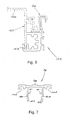
- the conduits 48 are held in the receptacles by conduit clips 50, one of which is illustrated at a larger scale in Figure 8 .
- the conduit clips are of extruded aluminium and extend for the full length of the component 16. In practice, with the conduits 48 located in the receptacles, the conduit clips 50 are pressed upwardly between the elements 46 such that laterally projecting lugs 52 on the lugs clip into complemental recesses 54 on the inner surfaces of the legs.
- each conduit clip 50 has an upper surface 56 of half round cross-section complemental to the external surface of the conduit 48. Accordingly, with the conduits held in position by the conduit clips, each receptacle and associated conduit clip, in combination, forms a cavity which completely and complementally surrounds the external surface of the conduit for the full length of the component 16.
- a suitable, thermally conductive gel or elastomer 58 is applied between the external surface of each conduit and the internal surface of the associated cavity to ensure that there is intimate, thermally transmitting contact between the component 16 and the conduit.
- the conduits 48 which are made of a material with high thermal conductivity, typically copper, are suitably connected to one another at the ends of the components 16 and are connected to a supply of water, which accordingly flows lengthways relative to the components.
- the intimate thermally transmitting relationship between the PV cells and the components 16, and between the components 16 and the conduits 48, combined with the high thermal conductivity of the component material, i.e. aluminium and of the adhesive 45 and 58, and the high thermal conductivity of the conduits, ensures that there is efficient heat transfer from the PV cells to the water conveyed by the conduits.
- the hot water which is produced by the apparatus 10 may be taken to a hot water container such as a geyser, or to a swimming pool or other location where hot water is required.
- the apparatus 10 accordingly serves the dual functions of electricity generation and hot water production.
- the components 16 are located side by side with their formations 20 and 22 in a side by side overlapping relationship the nature of which will be evident from the enlargement in Figure 1 .
- a connector 62 seen at a larger scale in Figure 9 , which has a base 64 and upstanding ribs 66 and 68.
- the connector is of extruded aluminium and extends for the length of the components.
- the rib 68 includes a laterally projecting clipping lug 70.
- the connector is positioned such that the longer rib 68 extends upwardly between opposing surfaces of the formations 20 and 22, with the shorter rib 66 received in a groove 72 in the formation 22 and with the clipping lug 70 making clipping engagement with a laterally extending lug 74 on the formation 22.
- the formations 20 and 22 and the connector 62 are connected to one another at each junction 60 by means of a component clip 76 which is illustrated at a larger scale in Figure 7 .
- the component clip which is of extruded aluminium and which extends for the length of the components 16, has a top portion 78 and downwardly extending legs 80 which include inwardly directed ribs 81 and arrowhead shape clipping lugs 82.
- the component clip 76 is driven downwardly relative to the assembly of formations 20 and 22 and connector 62 such that the ribs 80 bear inwardly on overlapping portions of the formations and the clipping lugs 82 make clipping engagement with respective lugs 84 and 86 on the formations 20 and 22.
- the component clip 76 secures the formations 20 and 22 and the connector 62 to one another, and thereby connects the adjacent components 16 to one another.
- the connectors 62 are fastened to the battens 12 by means of screws indicated diagrammatically by the numeral 90.
- battens are provided at a spacing of about 400mm so it will be understood that the interconnected components 16 are fastened to, and supported by, the battens at this regular interval over their length.
- the apparatus 10 includes, for each component 16, a light transmitting cover 92, in this case made of impact resistant acrylic.
- the cover 92 has downwardly projecting ribs 94 at positions corresponding to the positions of the undercut channel formations 36.
- the ribs 94 are of generally U-shaped cross-section. It will be noted that the ribs 94 have an upwardly tapering shape with an external profile complemental to the internal profile of the undercut channel formations 36, enabling the ribs to slide lengthways in the undercut channels.
- the covers 92 are positioned over the components 16 by sliding the ribs 94 lengthways into the undercut channel formations 36.
- the covers have a length corresponding to that of the components 16 and so completely cover the components when in position. It will be noted that the covers are positioned some distance above the components 16 and PV cells 42, and that when the covers are in position, downturned side edges 96 thereof locate over edge formations 98 of the formations 20. Sealing strips 100 are positioned in grooves 102 in the component clips 76 to seal against the upper surfaces of the covers when the component clips are installed.
- Further sealing strips 106 are positioned in grooves 106 in the edge formations 98 of the formations 20 to seal against the lower surfaces of the covers when the component clips are installed. The edges the covers are accordingly sealed top and bottom and are locked relative to the formations 20 and 22 by the component clips 76 when the latter are installed.
- the ends of the apparatus 10 are closed off by end members 110, a typical one of which is seen in Figure 5 .
- the end members which are in the form of plates of aluminium or other suitable material, span transverse across the ends of the components 10, i.e. in a direction parallel to the battens 12.
- the ends of the ribs 94 of the associated cover 92 locate in cut-outs 112 in the upper edge of the end member, and the end member is secured to the ends of the components 16 by means of screws or other fasteners (not shown) which pass through holes 116 in the end member into screw-receiving openings 118 in the formations 20, 22.
- a bowed strip of spring steel 120 which spans between grooves 122 at the sides of the end member 110 bear downwardly against the ends of the covers, and thereby reduce the chances of the covers lifting, fluttering or otherwise moving in windy conditions.
- the illustrated apparatus 10 actually forms part of a roof cladding, i.e. it actually forms part of the roof covering itself.
- flashings 123 such as that seen in Figure 4
- edge formations 125 such as that seen in Figure 6 are provided.
- the flashings 123 and edge formations 125 are in the form of aluminium extrusions and extend for the length of the components 16.
- the edge formation 122 has a shape generally corresponding to that of a formation 22, with the addition of an upwardly facing channel 124.
- the flashing has a downwardly extending main rib 126 and includes a downwardly facing channel 128.
- the edge formation 122 is located alongside the formation 20 which is at the side of the apparatus, the channel 128 of the flashing is positioned in a manner similar to the downturned side 96 of a cover, whereafter the component clip is applied to lock the edge components and flashing together, with a laterally extending portion 130 of the flashing extending some distance over the neighbouring roof cladding.
- the assembly of flashing and edge formation 122 is indicated in broken outline in Figure 6 .
- a corresponding assembly is provided at the other side edge of the apparatus 10 to mount a corresponding flashing over the neighbouring roof cladding on that side.
- the edge formation provided at the edge of the apparatus will have a shape corresponding to that of a formation 20.
- the apparatus 10 sits flush with neighbouring regions of the roof cladding and forms a part of the cladding between those regions.
- Figure 1 shows a single, complete component 10 and portions of adjacent components 10. In practice, there may be many such components making up the full width of the apparatus 10, the number of components being dependent on the amount electricity which is it required to generate and the amount of hot water which it is desired to produce.
- the apparatus 10 described above and illustrated in the drawings achieves the desired object of providing efficient cooling of the PV cells. This object is attained by means of a heat-transmitting support structure which supports both the PV cells and conduits and which conveys cooling water, and in which the PV cells and conduits are in intimate heating transmitting relationship with the support structure.
- the apparatus 10 provides the added advantage of providing heated water for other desired purposes.
- the described apparatus 10 has the further advantage that the covers 96 provide the PV cells with protection against impacts, thereby reducing the chances of possible cell breakage.
- the apparatus also solves another problem described at the outset, namely that of having to replace entire PV modules or panels in the event of breakage of a single cell or small group of cells.
- the components 16, each of which supports a part of the overall PV cell array are releasably connected to one another and so are individually replaceable. Referring to the enlargement in Figure 1 , it is possible to unclip the component clip 76 by inserting a suitable tool into one of the illustrated apertures 140 and manipulating the tool to prise the respective clipping formations apart from one another.
- the component clip 76 can be removed, whereafter the covers and individual components 16 can be detached from one another and from the connectors 62.
- This allows a component 16 which supports one or more broken or damaged PV cells to be replaced individually while the remainder of the apparatus 10 is left intact. In other words, it is not necessary to replace the entire panel or array or PV cells. It will be understood that where replacement of a single component 16 is undertaken it will be necessary to disconnect and reconnect the associated water-conveying conduits and electrical connections as required.
- the support structure 14 is itself extremely rigid. This is attributable to the design of the components 16 and in particular the fact that each component includes a number of integrally formed, transverse formations including the formations 20 and 22, the ribs 34, the formations 36 and the receptacles 44. These transverse formations considerably increase the resistance of the components 16 to bending under applied loads, for example the load imposed by a person walking on the apparatus. The bending resistance is of course aided by the fact that the components are themselves supported at small, regular intervals by the battens of the roof support structure. These features also contribute to achieving the objective of reducing possible breakage of or damage to the brittle PV cells.
- the numeral 150 indicates a bulk insulating material, for example polystyrene or other suitable material, which is located between the receptacles 44 and formations 20, 22, i.e. beneath the recesses 38 and 40. This insulation reduces downward loss of heat generated by the PV cells.
- the apparatus described above is designed for incorporation as part of a roof cladding structure, it will be understood that it would be quite possible to use the system in a retro-fit application in which it is mounted on an existing, complete roof cladding structure.
- the connectors 62 may be modified as necessary, or other mounting arrangements may be provided, to allow the assembled apparatus to be mounted on the existing roof cladding structure.
- the components 16 are in this embodiment provided with three recesses 38, 40, and hence are suitable for accommodating three rows of PV cells, it will be understood that it would be possible in other embodiments for the corresponding components to have only one or recesses, thereby allowing the component to accommodate only one or two row of PV cells, or for the components to have more than three recesses, thereby allowing the component to accommodate more than three separate rows of PV cells.
- the covers 92 are spaced above the recesses in the components 16, i.e. above the PV cells and accordingly form sealed air spaces above the PV cells while at the same time physically protecting the cells.
Description
- THIS invention relates to a solar energy collection apparatus.
- Photovoltaic (PV) cells are widely used to convert solar energy to electricity. However it is well known that such cells are relatively inefficient to the extent that in a typical case, a PV panel may convert only about 15% of incident solar energy to electricity leaving the balance to be dissipated as heat. It is furthermore well known that the efficiency of a PV cell decreases with increasing temperature. It has, for example, been said that for every degree Celsius rise in temperature the electrical power produced by a PV cell decreases by 0.5%.
- For these reasons, considerable research has been conducted into the dissipation of the heat generated by PV cells. Currently, the research is directed primarily towards improving heat removal from PV cells using natural convection. In these solutions, air gaps are created beneath and possibly around the PV panel such that natural convection of air through the gap(s) removes heat generated by the cells. A distinct and recognised problem with such arrangements is however the fact that the air is heated up during its passage through the gap(s) so that air initially entering the gap is cooler than that leaving the gap. This in turn means that less heat is removed from more elevated cells which accordingly run at lower electricity generating efficiency.
- Another problem with known PV cell configurations is the fact that the cells are extremely thin and brittle. Where the cells are made up into large modules or panels, as is typically the case, breakage of a single cell or small region of the module or panel will generally render the entire module or panel inoperative. In these situations it is generally necessary to replace the entire module or panel, typically at substantial cost.
- The above disadvantage of known PV module and panel configurations is particularly serious in cases where the modules or panels are mounted on a roof. In such situations, the modules and panels are readily prone to breakage as a result of sharp impacts from, for example, large hailstones or acts of vandalism in which vandals throw hard objects such as stones or bricks onto roof-mounted units, or as a result of workers or other persons walking or falling on the modules or panels.
- The specification of
US2008/011289 A1 describes a solar energy collection apparatus which can be mounted as a separate unit on an existing roof or other structure. The apparatus includes rigid support components of thermally conductive material which can be connected to one another. Solar cells are mounted to the support components in heat-transmitting relationship with the support components. Thermally conductive conduits are connected to the components and convey water to remove heat from the cells.US 2008/011289 describes an solar energy collection apparatus as defined in the preamble of independent claim 1. - One object of the present invention is to provide a solar energy collection system, based on PV cells or solar energy absorbers, with improved heat removal characteristics. A further object of the invention is to provide a solar energy collection apparatus in which the PV cells or solar energy absorbers are supported with sufficient rigidity to avoid or at least reduce the possibility of cell breakage but in which partial replacement of a solar panel can be achieved in a convenient manner should breakage take place.
- The above objects are met by a solar energy collection apparatus as set forth in claim 1 and preferred features are set forth in the dependent claims.
- The objective of heat removal from the PV cells or solar energy absorbers is achieved by the water-conveying conduits. It will be understood that the water which is conveyed in the conduits and is thermally heated by the PV cells or solar energy absorbers can be used in other applications requiring heated water. Examples of such applications are geysers and swimming pools where an elevated water temperature is desired.
- Preferably the rigid support structure comprises a plurality of elongate, rigid, extruded components of thermally conductive material which are connected releasably to one another, each component defining at least one elongate recess in which an elongate row of PV cells or solar energy absorbers is/are fixed in heat transmitting relationship with the material of the component. The releasable interconnection of components is conveniently achieved by way of releasable component clips.
- Typically, extruded components of the rigid support structure include integral, transverse formations along long edges of the components, the formations of adjacent components lying alongside one another and the system including component clips which engage the formations releasably to connect the components to one another.
- In the preferred arrangement, each cover has side edges which are connected releasably to the first formations by the component clips. There may be seals between the side edges of the cover and the transverse formations and between the side edges of the cover and the component clips.
- Typically also, the components of the rigid support structure include further integral, transversely projecting formations extending longitudinally and defining undercut channels and the cover includes integral, transverse ribs which are received in sliding manner in the channels.
- The components of the rigid support structure may also include integral, transversely oriented receptacles in which the conduits are received, the system including thermally conductive conduit clips which are clipped into the receptacles to anchor the conduits in the receptacles. Preferably each receptacle and associated clip, in combination, define a cavity which is complemental in shape to the external surface of a conduit. Typically the conduit has a round cylindrical outer surface and the receptacle and associated clip in combination define a cavity with an internal surface which is complementally round cylindrical in cross-section. For improved thermal transmission there may be a thermally conductive elastomer between the external surface of the conduit and the internal surface of the cavity.
- The objective of supporting the PV cells or solar energy absorbers with sufficient rigidity to avoid or at least reduce the possibility of cell or absorber breakage but allowing partial replacement is achieved by the rigidity of the extruded components, each carrying some of the cells, and the fact that the components are connected to one another in a releasable manner. Accordingly if one or only a few cells or absorbers should be damaged or broken it is possible to remove and replace only the affected component(s). The rigidity of the extruded components is attributable in the main to the various transverse formations which provide the components with an increased resistance to bending.
- In the preferred embodiments using PV cells, each recess has a width corresponding to that of a single PV cell, i.e. each recess accommodates a single row of PV cells. Thermal transmission is improved by providing, in each recess, a thermally conductive elastomer between the bases of the PV cells and the base of the recess.
- The apparatus may include connectors which are connectable to battens of the roof support structure and are connected releasably to the transverse formations. Conveniently the connectors are connected releasably to the first formations by the action of the component clips.
- The apparatus may comprise extruded edge members which are connected releasably to components at opposite sides of the rigid support structure by the component clips and to which can be attached flashing members for overlapping neighbouring regions of the roof cladding structure on opposite sides of the apparatus. It may also comprise end members connected to ends of the components in order to provide the solar energy collection apparatus with closed ends.
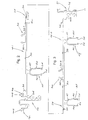
- The invention will now be described in more detail, by way of example only, with reference to the accompanying drawings in which:
- Figure 1
- shows a cross-sectional view of a solar energy collection apparatus according to this invention;
- Figures 2 to 4
- show cross-sectional views of extruded components seen in
Figure 1 ; - Figure 5
- an elevation view of and end member;
- Figure 6
- shows a cross-sectional view of an edge member;
- Figure 7
- shows a cross-sectional view of the component clip seen in
Figure 1 ; - Figure 8
- shows a cross-sectional view of the conduit clip seen in
Figure 1 ; and - Figure 9
- shows a cross-sectional view of the connector seen in
Figure 1 . - The solar energy collection apparatus 10 seen in
Figure 1 is designed to form part of a roof cladding structure, i.e. the apparatus will actually form part of the roof cladding, typically between neighbouring regions of the roof cladding which may, for example, consist of tiles, metal sheets or the like. - The numeral 12 in
Figure 1 indicates a batten or purlin, typically of timber, which spans transversely over rafters (not shown) in a conventional pitched roof structure. - The system 10 includes a rigid support structure, indicated generally by the numeral 14, which includes elongate, extruded
components 16 of a material with a high degree of thermal conductivity, in this case, aluminium. Thecomponents 16 are elongate in a direction into the plane of the paper inFigure 1 . - In the illustrated embodiment, each extruded
component 16 is made up of two extruded sub-components 16.1 and 16.2 which are illustrated at a larger scale inFigures 2 and 3 respectively. The sub-component 16.1 includes anintegral formation 20 which is transverse to the length of the extrusion, which has the illustrated cross-sectional shape and which runs for the length of the sub-component along one side edge. The sub-component 16.2 also includes anintegral formation 22 which is transverse to the length of the extrusion, which has the illustrated cross-sectional shape and which runs for the length of the sub-component along a side edge. At their opposite side edges the sub-components 16.1 and 16.2 includeedge formations Figure 1 , with atongue 28 of theedge formation 26 locating in agroove 30 of the other edge formation. At this junction, the sub-components are fixed rigidly to one another by means of suitable fasteners indicated diagrammatically by the numeral 32 inFigure 1 . - Although in this embodiment, each
component 16 is composed of two sub-components it will be understood that in other embodiments, each component may be formed as a one-piece, integral extrusion or of more than two interconnected sub-components. - The
component 16 includesupstanding ribs 34 as well as transversely projectingformations 36 each composed of upstanding elements 36.1, 36.2 which define an undercut channel between them. The ribs and formatioins 36 extend longitudinally for the length of thecomponent 16. Between eachrib 34 and aformation 36 there is arecess 38 extending for the length of the component. Afurther recess 40 is defined between theformations 36. - The
recesses PV cells 42. In practice, eachrecess single cell 42, typically about 100mm. In each recess there is a single row ofcells 42, the row extending for the length of thecomponent 16. Thecells 42, which typically have abacking 44 of Tedlar® or other suitable thermally conductive film, are fixed in the recess by a thermally conductive adhesive 45, in this case a thermally conductive elastomeric adhesive such that marketed as Dow Corning 3-6655. In practice, the cells are embedded in the adhesive in the recess and so are in an intimate, thermally transmitting relationship with the thermally conductive material of thecomponent 16, i.e. aluminium in this case. - The electrical connections between the adjacent cells are not shown in the drawings, but may be taken as conventional.
- Each
component 16 also includes integral, transverse, downwardly projecting receptacles orhousings 44 defined by spaced apartelements 46. Thereceptacles 44 extend for the length of the components and havebases 47 of half-round cross-section. A longitudinally extendingconduit 48 of round cross-section is located in each receptacle. As illustrated, the base of each receptacle is complemental in shape to one half of the external surface of aconduit 48. Theconduits 48 are held in the receptacles by conduit clips 50, one of which is illustrated at a larger scale inFigure 8 . The conduit clips are of extruded aluminium and extend for the full length of thecomponent 16. In practice, with theconduits 48 located in the receptacles, the conduit clips 50 are pressed upwardly between theelements 46 such that laterally projectinglugs 52 on the lugs clip intocomplemental recesses 54 on the inner surfaces of the legs. - As illustrated, each
conduit clip 50 has anupper surface 56 of half round cross-section complemental to the external surface of theconduit 48. Accordingly, with the conduits held in position by the conduit clips, each receptacle and associated conduit clip, in combination, forms a cavity which completely and complementally surrounds the external surface of the conduit for the full length of thecomponent 16. A suitable, thermally conductive gel orelastomer 58 is applied between the external surface of each conduit and the internal surface of the associated cavity to ensure that there is intimate, thermally transmitting contact between thecomponent 16 and the conduit. - In use, the
conduits 48, which are made of a material with high thermal conductivity, typically copper, are suitably connected to one another at the ends of thecomponents 16 and are connected to a supply of water, which accordingly flows lengthways relative to the components. The intimate thermally transmitting relationship between the PV cells and thecomponents 16, and between thecomponents 16 and theconduits 48, combined with the high thermal conductivity of the component material, i.e. aluminium and of the adhesive 45 and 58, and the high thermal conductivity of the conduits, ensures that there is efficient heat transfer from the PV cells to the water conveyed by the conduits. - The water accordingly cools the PV cells and enables them to operate efficiently in their electricity producing duty.
- As indicated above the hot water which is produced by the apparatus 10 may be taken to a hot water container such as a geyser, or to a swimming pool or other location where hot water is required. The apparatus 10 accordingly serves the dual functions of electricity generation and hot water production.
- Referring to
Figure 1 , thecomponents 16 are located side by side with theirformations Figure 1 . At each junction 60 betweenadjacent components 16, there is also aconnector 62, seen at a larger scale inFigure 9 , which has abase 64 andupstanding ribs 66 and 68. The connector is of extruded aluminium and extends for the length of the components. Therib 68 includes a laterally projecting clipping lug 70.The connector is positioned such that thelonger rib 68 extends upwardly between opposing surfaces of theformations groove 72 in theformation 22 and with the clippinglug 70 making clipping engagement with a laterally extendinglug 74 on theformation 22. - The
formations connector 62 are connected to one another at each junction 60 by means of acomponent clip 76 which is illustrated at a larger scale inFigure 7 . The component clip, which is of extruded aluminium and which extends for the length of thecomponents 16, has a top portion 78 and downwardly extending legs 80 which include inwardly directed ribs 81 and arrowhead shape clipping lugs 82. As illustrated in the enlargement inFigure 1 , thecomponent clip 76 is driven downwardly relative to the assembly offormations connector 62 such that the ribs 80 bear inwardly on overlapping portions of the formations and the clipping lugs 82 make clipping engagement withrespective lugs 84 and 86 on theformations component clip 76 secures theformations connector 62 to one another, and thereby connects theadjacent components 16 to one another. - The
connectors 62 are fastened to the battens 12 by means of screws indicated diagrammatically by the numeral 90. In a typical pitched roof construction battens are provided at a spacing of about 400mm so it will be understood that theinterconnected components 16 are fastened to, and supported by, the battens at this regular interval over their length. - Referring again to
Figure 1 , the apparatus 10 includes, for eachcomponent 16, alight transmitting cover 92, in this case made of impact resistant acrylic. Thecover 92 has downwardly projectingribs 94 at positions corresponding to the positions of the undercutchannel formations 36. Theribs 94 are of generally U-shaped cross-section. It will be noted that theribs 94 have an upwardly tapering shape with an external profile complemental to the internal profile of the undercutchannel formations 36, enabling the ribs to slide lengthways in the undercut channels. - During assembly, before the component clips 72 are clipped into position, the
covers 92 are positioned over thecomponents 16 by sliding theribs 94 lengthways into the undercutchannel formations 36. The covers have a length corresponding to that of thecomponents 16 and so completely cover the components when in position. It will be noted that the covers are positioned some distance above thecomponents 16 andPV cells 42, and that when the covers are in position, downturned side edges 96 thereof locate overedge formations 98 of theformations 20. Sealing strips 100 are positioned ingrooves 102 in the component clips 76 to seal against the upper surfaces of the covers when the component clips are installed. Further sealingstrips 106 are positioned ingrooves 106 in theedge formations 98 of theformations 20 to seal against the lower surfaces of the covers when the component clips are installed. The edges the covers are accordingly sealed top and bottom and are locked relative to theformations - The ends of the apparatus 10 are closed off by end members 110, a typical one of which is seen in
Figure 5 . The end members, which are in the form of plates of aluminium or other suitable material, span transverse across the ends of the components 10, i.e. in a direction parallel to the battens 12. At each end member, the ends of theribs 94 of the associatedcover 92 locate in cut-outs 112 in the upper edge of the end member, and the end member is secured to the ends of thecomponents 16 by means of screws or other fasteners (not shown) which pass through holes 116 in the end member into screw-receiving openings 118 in theformations grooves 122 at the sides of the end member 110 bear downwardly against the ends of the covers, and thereby reduce the chances of the covers lifting, fluttering or otherwise moving in windy conditions. - As indicated previously, the illustrated apparatus 10 actually forms part of a roof cladding, i.e. it actually forms part of the roof covering itself. To provide a seal between the apparatus 10 and regions of the remaining roof cladding, for example tiles, sheet metal or the like, lying to the sides of the apparatus,
flashings 123 such as that seen inFigure 4 andedge formations 125 such as that seen inFigure 6 are provided. Theflashings 123 andedge formations 125 are in the form of aluminium extrusions and extend for the length of thecomponents 16. - Referring to
Figure 6 , it will be noted that theedge formation 122 has a shape generally corresponding to that of aformation 22, with the addition of an upwardly facingchannel 124. As shown inFigure 4 , the flashing has a downwardly extendingmain rib 126 and includes a downwardly facingchannel 128. During assembly, and before installation of the component clip at a side edge of the apparatus 10, theedge formation 122 is located alongside theformation 20 which is at the side of the apparatus, thechannel 128 of the flashing is positioned in a manner similar to thedownturned side 96 of a cover, whereafter the component clip is applied to lock the edge components and flashing together, with a laterally extendingportion 130 of the flashing extending some distance over the neighbouring roof cladding. The assembly of flashing andedge formation 122 is indicated in broken outline inFigure 6 . - It will be understood that a corresponding assembly is provided at the other side edge of the apparatus 10 to mount a corresponding flashing over the neighbouring roof cladding on that side. In this case, the edge formation provided at the edge of the apparatus will have a shape corresponding to that of a
formation 20. - In the final assembly, the apparatus 10 sits flush with neighbouring regions of the roof cladding and forms a part of the cladding between those regions.
-
Figure 1 shows a single, complete component 10 and portions of adjacent components 10. In practice, there may be many such components making up the full width of the apparatus 10, the number of components being dependent on the amount electricity which is it required to generate and the amount of hot water which it is desired to produce. - The apparatus 10 described above and illustrated in the drawings achieves the desired object of providing efficient cooling of the PV cells. This object is attained by means of a heat-transmitting support structure which supports both the PV cells and conduits and which conveys cooling water, and in which the PV cells and conduits are in intimate heating transmitting relationship with the support structure. The apparatus 10 provides the added advantage of providing heated water for other desired purposes.
- The described apparatus 10 has the further advantage that the
covers 96 provide the PV cells with protection against impacts, thereby reducing the chances of possible cell breakage. However, the apparatus also solves another problem described at the outset, namely that of having to replace entire PV modules or panels in the event of breakage of a single cell or small group of cells. In the present case, as described above, thecomponents 16, each of which supports a part of the overall PV cell array, are releasably connected to one another and so are individually replaceable. Referring to the enlargement inFigure 1 , it is possible to unclip thecomponent clip 76 by inserting a suitable tool into one of the illustrated apertures 140 and manipulating the tool to prise the respective clipping formations apart from one another. Once thecomponent clip 76 has been unclipped it can be removed, whereafter the covers andindividual components 16 can be detached from one another and from theconnectors 62. This allows acomponent 16 which supports one or more broken or damaged PV cells to be replaced individually while the remainder of the apparatus 10 is left intact. In other words, it is not necessary to replace the entire panel or array or PV cells. It will be understood that where replacement of asingle component 16 is undertaken it will be necessary to disconnect and reconnect the associated water-conveying conduits and electrical connections as required. - Apart from the protection provided by the
covers 96, thesupport structure 14 is itself extremely rigid. This is attributable to the design of thecomponents 16 and in particular the fact that each component includes a number of integrally formed, transverse formations including theformations ribs 34, theformations 36 and thereceptacles 44. These transverse formations considerably increase the resistance of thecomponents 16 to bending under applied loads, for example the load imposed by a person walking on the apparatus. The bending resistance is of course aided by the fact that the components are themselves supported at small, regular intervals by the battens of the roof support structure. These features also contribute to achieving the objective of reducing possible breakage of or damage to the brittle PV cells. - Referring again to
Figure 1 , the numeral 150 indicates a bulk insulating material, for example polystyrene or other suitable material, which is located between thereceptacles 44 andformations recesses - Although the apparatus described above is designed for incorporation as part of a roof cladding structure, it will be understood that it would be quite possible to use the system in a retro-fit application in which it is mounted on an existing, complete roof cladding structure. In this case, the
connectors 62 may be modified as necessary, or other mounting arrangements may be provided, to allow the assembled apparatus to be mounted on the existing roof cladding structure. - Also, although the
components 16 are in this embodiment provided with threerecesses - In situations where only a water heating function is required, as opposed to the dual function of electricity production and water heating, it is possible to replace the PV cells with conventional solar energy absorbers in the
recesses conduits 48 via the interchangeablesupport structure components 16 and conduits which will, again, be of thermally conductive material such as copper. - The
covers 92 are spaced above the recesses in thecomponents 16, i.e. above the PV cells and accordingly form sealed air spaces above the PV cells while at the same time physically protecting the cells.
Claims (15)
- A solar energy collection apparatus (10) comprising a rigid support structure (14) which includes rigid support components (16) made of thermally conductive material connected releasably to one another and carrying operatively downwardly projecting conduit-receiving receptacles (44), PV cells (42) or solar energy absorbers mounted on the components of the support structure in heat transmitting relationship with the components, thermally conductive conduits (48) which are connected to the components of the support structure in heat transmitting relationship with the components and which are arranged to convey water to remove heat from the PV cells or solar energy absorbers via the components and conduits, bulk thermal insulation (150) located beneath recesses (38,40) of the components in which the PV cells (42) or solar energy absorbers are accommodated in order to reduce downward loss of heat generated by the PV cells or solar energy absorbers, and at least one removable, light-transmitting cover (92) spaced above and extending over the cells or solar energy absorbers, characterised in that:the rigid support structure is configured to be connected to a roof support structure (12) such that the apparatus (10) forms part of a roof cladding structure;the apparatus includes thermally conductive conduit clips (50) which are clipped into the receptacles (44) to anchor the conduits (48) in the receptacles, andeach receptacle and associated clip, in combination, defines a conduit-receiving cavity which is complemental in shape to the external surface of a conduit.
- A solar energy collection apparatus according to claim 1 wherein the rigid support structure (14) comprises a plurality of elongate, extruded components (16) of thermally conductive material which are connected releasably to one another, each component defining at least one elongate recess (38, 40) in which a row of cells (42) or solar energy absorbers is/are fixed in heat transmitting relationship with the component.
- A solar energy collection apparatus according to claim 2 wherein the apparatus includes releasable component clips (76) to connect the components (16) of the rigid support structure (14) to one another.
- A solar energy collection apparatus according to claim 3 wherein the components (16) of the rigid support structure (14) include integral, transverse formations (20, 22) along long edges of the components, the formations of adjacent components lying alongside one another with the component clips (76) serving to connect the formations releasably to one another.
- A solar energy collection apparatus according to claim 4 wherein each cover (92) has side edges (96) which are connected releasably to the transverse formations (20. 22) by the component clips (76).
- A solar energy collection apparatus according to claim 5 and comprising seals (106, 100) between the side edges (96) of each cover (92) and the transverse formations (20, 22) and between the side edges of each cover and the component clips (76).
- A solar energy collection apparatus according to either one of claims 5 or 6 wherein the components (16) of the rigid support structure (14) include further integral, transversely projecting formations (36) extending longitudinally and defining undercut channels, and each cover (92) includes integral, transverse ribs (94) which are received in sliding manner in the undercut channels.
- A solar energy collection apparatus according to claim 7 wherein the formations (36) defining the undercut channels project upwardly relative to the support structure (14).
- A solar energy collection apparatus according to any one of the preceding claims wherein the receptacles (44) and conduit clips (50) extend for the full length of the rigid support components (16).
- A solar energy collection apparatus according to claim 8 or claim 9 and comprising a thermally conductive elastomer(58) between the external surface of each conduit (48) and the internal surface of the cavity in which the conduit is received.
- A solar energy collection apparatus according to any one of claims 4 to 10 and comprising connectors (62) which are connectable to battens (12) of the roof support structure and are connected releasably to the transverse formations (20, 22) of the components (16).
- A solar energy collection apparatus according to claim 11 wherein the connectors (62) are connected releasably to the transverse formations (20, 22) of the components by the component clips (76).
- A solar energy collection apparatus according to claim 11 or claim 12 and comprising extruded edge members (125) which are connected releasably to components (20, 22) at opposite sides of the rigid support structure by component clips and to which can be attached flashing members (123) for overlapping neighbouring regions of the roof cladding structure on opposite sides of the apparatus (10).
- A solar energy collection apparatus according to any one of claims 11 to 13 and comprising end members (110) connected to ends of the components (16) in order to provide the apparatus (10) with closed ends.
- A solar energy collection apparatus according to any one of claims 2 to 14 wherein each recess (38, 40) has a width corresponding to that of a single PV cell (42), each recess accommodating a row of single PV cells with a thermally conductive elastomer (45) between the PV cells and a base of the recess.
Applications Claiming Priority (2)
| Application Number | Priority Date | Filing Date | Title |
|---|---|---|---|
| ZA200901066 | 2009-02-16 | ||
| PCT/IB2010/050681 WO2010092559A2 (en) | 2009-02-16 | 2010-02-16 | Solar energy collection apparatus |
Publications (2)
| Publication Number | Publication Date |
|---|---|
| EP2396828A2 EP2396828A2 (en) | 2011-12-21 |
| EP2396828B1 true EP2396828B1 (en) | 2013-11-06 |
Family
ID=42562130
Family Applications (1)
| Application Number | Title | Priority Date | Filing Date |
|---|---|---|---|
| EP10705429.8A Active EP2396828B1 (en) | 2009-02-16 | 2010-02-16 | Solar energy collection apparatus |
Country Status (9)
| Country | Link |
|---|---|
| US (1) | US20130199596A1 (en) |
| EP (1) | EP2396828B1 (en) |
| CN (1) | CN102396080B (en) |
| AP (1) | AP2011005869A0 (en) |
| AU (1) | AU2010213398B2 (en) |
| ES (1) | ES2439997T3 (en) |
| PT (1) | PT2396828E (en) |
| WO (1) | WO2010092559A2 (en) |
| ZA (1) | ZA201106581B (en) |
Families Citing this family (4)
| Publication number | Priority date | Publication date | Assignee | Title |
|---|---|---|---|---|
| US8646228B2 (en) * | 2009-03-24 | 2014-02-11 | Certainteed Corporation | Photovoltaic systems, methods for installing photovoltaic systems, and kits for installing photovoltaic systems |
| FR2966228B1 (en) * | 2010-10-18 | 2014-12-19 | Frederic Paul Francois Marcais | MULTIPURPOSE FIXING SUPPORT FOR THE INSTALLATION OF THERMAL RECOVERY MODULES FOR SOLAR RADIATION |
| ITRM20110686A1 (en) * | 2011-12-23 | 2013-06-24 | Umberto Berti | ALUMINUM COMPOSITE BEARING STRUCTURE CONSISTS OF PAIRING BETWEEN PHOTOVOLTAIC MODULES AND ELEMENTS IN ALUMINUM WITH RADIANT EFFECT, CALLED `BDRSTRIP¿ |
| CN107210328A (en) * | 2014-09-01 | 2017-09-26 | 康福科技有限公司 | Solar collector for generating |
Family Cites Families (6)
| Publication number | Priority date | Publication date | Assignee | Title |
|---|---|---|---|---|
| US5232518A (en) * | 1990-11-30 | 1993-08-03 | United Solar Systems Corporation | Photovoltaic roof system |
| US5589006A (en) * | 1993-11-30 | 1996-12-31 | Canon Kabushiki Kaisha | Solar battery module and passive solar system using same |
| US6105317A (en) * | 1997-09-24 | 2000-08-22 | Matsushita Electric Works, Ltd. | Mounting system for installing an array of solar battery modules of a panel-like configuration on a roof |
| US20080011289A1 (en) * | 2006-07-14 | 2008-01-17 | National Science And Technology Development Agency | Photovoltaic thermal (PVT) collector |
| US7939747B2 (en) * | 2007-04-06 | 2011-05-10 | Bradley Owen Stimson | Solar heating method and apparatus |
| CN201160074Y (en) * | 2007-09-06 | 2008-12-03 | 比亚迪股份有限公司 | Strutting piece, processing mould and solar cell module including the strutting piece |
-
2010
- 2010-02-16 AU AU2010213398A patent/AU2010213398B2/en active Active
- 2010-02-16 WO PCT/IB2010/050681 patent/WO2010092559A2/en active Application Filing
- 2010-02-16 PT PT107054298T patent/PT2396828E/en unknown
- 2010-02-16 US US13/201,822 patent/US20130199596A1/en not_active Abandoned
- 2010-02-16 AP AP2011005869A patent/AP2011005869A0/en unknown
- 2010-02-16 CN CN201080016600.7A patent/CN102396080B/en active Active
- 2010-02-16 ES ES10705429.8T patent/ES2439997T3/en active Active
- 2010-02-16 EP EP10705429.8A patent/EP2396828B1/en active Active
-
2011
- 2011-09-08 ZA ZA2011/06581A patent/ZA201106581B/en unknown
Also Published As
| Publication number | Publication date |
|---|---|
| EP2396828A2 (en) | 2011-12-21 |
| CN102396080A (en) | 2012-03-28 |
| PT2396828E (en) | 2014-01-22 |
| ZA201106581B (en) | 2012-11-28 |
| US20130199596A1 (en) | 2013-08-08 |
| WO2010092559A3 (en) | 2011-06-23 |
| WO2010092559A2 (en) | 2010-08-19 |
| AU2010213398A1 (en) | 2011-10-06 |
| ES2439997T3 (en) | 2014-01-27 |
| CN102396080B (en) | 2014-11-05 |
| AU2010213398B2 (en) | 2015-07-16 |
| AP2011005869A0 (en) | 2011-10-31 |
Similar Documents
| Publication | Publication Date | Title |
|---|---|---|
| US5935343A (en) | Combined solar collector and photovoltaic cells | |
| EP2655759B1 (en) | Building integrated thermal electric hybrid roofing system | |
| GB2448920A (en) | Solar energy collector for obtaining electrical and thermal energy | |
| US8739478B1 (en) | Integrated thermal module and back plate structure and related methods | |
| KR20080009264A (en) | Roof cover or facade siding | |
| EP2396828B1 (en) | Solar energy collection apparatus | |
| EP2216829A1 (en) | Solar roof tile assembly | |
| CA2743382A1 (en) | Photovoltaic system, photovoltaic module and method for assembling a photovoltaic system | |
| WO2011107835A1 (en) | Building cover element with an integrated energy production device | |
| US20160087131A1 (en) | Facade element or roof element | |
| US9909781B2 (en) | Solar cell roof tiles | |
| US8946542B1 (en) | Solar module bonding method integrated into a pan structure | |
| EP0940859B1 (en) | Combined solar collector and photovoltaic cells | |
| AU2022224751B2 (en) | Solar Roof Panel | |
| JP5322103B2 (en) | Drainage structure of solar energy conversion module integrated exterior structure | |
| JP6444706B2 (en) | PV module | |
| EP2823238A1 (en) | A solar collector and solar panel with solar cells for the roof of a building | |
| WO2016035005A1 (en) | Solar collector for electricity generation | |
| KR101235720B1 (en) | Shingle type photovoltaic module | |
| KR102490041B1 (en) | Roof Integrated photovoltaic module assembly and its construction method | |
| JP2012172950A (en) | Snow melting device for solar panel | |
| JP5527675B2 (en) | Drainage structure of solar energy conversion module integrated exterior structure | |
| KR20120017322A (en) | Combiniing structure for fixing solar cell module | |
| WO2017058086A1 (en) | Solar cell module | |
| EP3356748A1 (en) | Solar cell module |
Legal Events
| Date | Code | Title | Description |
|---|---|---|---|
| PUAI | Public reference made under article 153(3) epc to a published international application that has entered the european phase |
Free format text: ORIGINAL CODE: 0009012 |
|
| 17P | Request for examination filed |
Effective date: 20110915 |
|
| AK | Designated contracting states |
Kind code of ref document: A2 Designated state(s): AT BE BG CH CY CZ DE DK EE ES FI FR GB GR HR HU IE IS IT LI LT LU LV MC MK MT NL NO PL PT RO SE SI SK SM TR |
|
| DAX | Request for extension of the european patent (deleted) | ||
| 17Q | First examination report despatched |
Effective date: 20120910 |
|
| REG | Reference to a national code |
Ref country code: DE Ref legal event code: R079 Ref document number: 602010011478 Country of ref document: DE Free format text: PREVIOUS MAIN CLASS: H01L0031052000 Ipc: F24J0002040000 |
|
| RIC1 | Information provided on ipc code assigned before grant |
Ipc: F24J 2/52 20060101ALI20130417BHEP Ipc: H01L 31/052 20060101ALI20130417BHEP Ipc: F24J 2/46 20060101ALI20130417BHEP Ipc: H01L 31/058 20060101ALI20130417BHEP Ipc: F24J 2/26 20060101ALI20130417BHEP Ipc: F24J 2/00 20060101ALI20130417BHEP Ipc: F24J 2/04 20060101AFI20130417BHEP Ipc: F24J 2/50 20060101ALI20130417BHEP |
|
| GRAP | Despatch of communication of intention to grant a patent |
Free format text: ORIGINAL CODE: EPIDOSNIGR1 |
|
| INTG | Intention to grant announced |
Effective date: 20130702 |
|
| GRAS | Grant fee paid |
Free format text: ORIGINAL CODE: EPIDOSNIGR3 |
|
| GRAA | (expected) grant |
Free format text: ORIGINAL CODE: 0009210 |
|
| AK | Designated contracting states |
Kind code of ref document: B1 Designated state(s): AT BE BG CH CY CZ DE DK EE ES FI FR GB GR HR HU IE IS IT LI LT LU LV MC MK MT NL NO PL PT RO SE SI SK SM TR |
|
| REG | Reference to a national code |
Ref country code: GB Ref legal event code: FG4D |
|
| REG | Reference to a national code |
Ref country code: CH Ref legal event code: EP |
|
| REG | Reference to a national code |
Ref country code: AT Ref legal event code: REF Ref document number: 639765 Country of ref document: AT Kind code of ref document: T Effective date: 20131215 |
|
| REG | Reference to a national code |
Ref country code: IE Ref legal event code: FG4D |
|
| REG | Reference to a national code |
Ref country code: DE Ref legal event code: R096 Ref document number: 602010011478 Country of ref document: DE Effective date: 20140102 |
|
| REG | Reference to a national code |
Ref country code: DE Ref legal event code: R081 Ref document number: 602010011478 Country of ref document: DE Owner name: CONVER-TEK PROPRIETARY LTD., ZA Free format text: FORMER OWNER: DAVIS, BEVAN JOHN, GERMISTON, ZA |
|
| REG | Reference to a national code |
Ref country code: PT Ref legal event code: SC4A Free format text: AVAILABILITY OF NATIONAL TRANSLATION Effective date: 20140115 |
|
| REG | Reference to a national code |
Ref country code: ES Ref legal event code: FG2A Ref document number: 2439997 Country of ref document: ES Kind code of ref document: T3 Effective date: 20140127 |
|
| REG | Reference to a national code |
Ref country code: NL Ref legal event code: VDEP Effective date: 20131106 |
|
| REG | Reference to a national code |
Ref country code: AT Ref legal event code: MK05 Ref document number: 639765 Country of ref document: AT Kind code of ref document: T Effective date: 20131106 |
|
| REG | Reference to a national code |
Ref country code: GR Ref legal event code: EP Ref document number: 20140400235 Country of ref document: GR Effective date: 20140317 |
|
| REG | Reference to a national code |
Ref country code: LT Ref legal event code: MG4D |
|
| PG25 | Lapsed in a contracting state [announced via postgrant information from national office to epo] |
Ref country code: IS Free format text: LAPSE BECAUSE OF FAILURE TO SUBMIT A TRANSLATION OF THE DESCRIPTION OR TO PAY THE FEE WITHIN THE PRESCRIBED TIME-LIMIT Effective date: 20140306 Ref country code: LT Free format text: LAPSE BECAUSE OF FAILURE TO SUBMIT A TRANSLATION OF THE DESCRIPTION OR TO PAY THE FEE WITHIN THE PRESCRIBED TIME-LIMIT Effective date: 20131106 Ref country code: SE Free format text: LAPSE BECAUSE OF FAILURE TO SUBMIT A TRANSLATION OF THE DESCRIPTION OR TO PAY THE FEE WITHIN THE PRESCRIBED TIME-LIMIT Effective date: 20131106 Ref country code: NL Free format text: LAPSE BECAUSE OF FAILURE TO SUBMIT A TRANSLATION OF THE DESCRIPTION OR TO PAY THE FEE WITHIN THE PRESCRIBED TIME-LIMIT Effective date: 20131106 Ref country code: FI Free format text: LAPSE BECAUSE OF FAILURE TO SUBMIT A TRANSLATION OF THE DESCRIPTION OR TO PAY THE FEE WITHIN THE PRESCRIBED TIME-LIMIT Effective date: 20131106 Ref country code: NO Free format text: LAPSE BECAUSE OF FAILURE TO SUBMIT A TRANSLATION OF THE DESCRIPTION OR TO PAY THE FEE WITHIN THE PRESCRIBED TIME-LIMIT Effective date: 20140206 Ref country code: HR Free format text: LAPSE BECAUSE OF FAILURE TO SUBMIT A TRANSLATION OF THE DESCRIPTION OR TO PAY THE FEE WITHIN THE PRESCRIBED TIME-LIMIT Effective date: 20131106 |
|
| PG25 | Lapsed in a contracting state [announced via postgrant information from national office to epo] |
Ref country code: LV Free format text: LAPSE BECAUSE OF FAILURE TO SUBMIT A TRANSLATION OF THE DESCRIPTION OR TO PAY THE FEE WITHIN THE PRESCRIBED TIME-LIMIT Effective date: 20131106 Ref country code: BE Free format text: LAPSE BECAUSE OF FAILURE TO SUBMIT A TRANSLATION OF THE DESCRIPTION OR TO PAY THE FEE WITHIN THE PRESCRIBED TIME-LIMIT Effective date: 20131106 Ref country code: AT Free format text: LAPSE BECAUSE OF FAILURE TO SUBMIT A TRANSLATION OF THE DESCRIPTION OR TO PAY THE FEE WITHIN THE PRESCRIBED TIME-LIMIT Effective date: 20131106 |
|
| PGFP | Annual fee paid to national office [announced via postgrant information from national office to epo] |
Ref country code: FR Payment date: 20140213 Year of fee payment: 5 Ref country code: IT Payment date: 20140113 Year of fee payment: 5 Ref country code: TR Payment date: 20140107 Year of fee payment: 5 |
|
| PGFP | Annual fee paid to national office [announced via postgrant information from national office to epo] |
Ref country code: PT Payment date: 20140121 Year of fee payment: 5 |
|
| PG25 | Lapsed in a contracting state [announced via postgrant information from national office to epo] |
Ref country code: EE Free format text: LAPSE BECAUSE OF FAILURE TO SUBMIT A TRANSLATION OF THE DESCRIPTION OR TO PAY THE FEE WITHIN THE PRESCRIBED TIME-LIMIT Effective date: 20131106 |
|
| REG | Reference to a national code |
Ref country code: DE Ref legal event code: R097 Ref document number: 602010011478 Country of ref document: DE |
|
| PG25 | Lapsed in a contracting state [announced via postgrant information from national office to epo] |
Ref country code: CZ Free format text: LAPSE BECAUSE OF FAILURE TO SUBMIT A TRANSLATION OF THE DESCRIPTION OR TO PAY THE FEE WITHIN THE PRESCRIBED TIME-LIMIT Effective date: 20131106 Ref country code: RO Free format text: LAPSE BECAUSE OF FAILURE TO SUBMIT A TRANSLATION OF THE DESCRIPTION OR TO PAY THE FEE WITHIN THE PRESCRIBED TIME-LIMIT Effective date: 20131106 Ref country code: SK Free format text: LAPSE BECAUSE OF FAILURE TO SUBMIT A TRANSLATION OF THE DESCRIPTION OR TO PAY THE FEE WITHIN THE PRESCRIBED TIME-LIMIT Effective date: 20131106 Ref country code: PL Free format text: LAPSE BECAUSE OF FAILURE TO SUBMIT A TRANSLATION OF THE DESCRIPTION OR TO PAY THE FEE WITHIN THE PRESCRIBED TIME-LIMIT Effective date: 20131106 |
|
| PLBE | No opposition filed within time limit |
Free format text: ORIGINAL CODE: 0009261 |
|
| STAA | Information on the status of an ep patent application or granted ep patent |
Free format text: STATUS: NO OPPOSITION FILED WITHIN TIME LIMIT |
|
| PG25 | Lapsed in a contracting state [announced via postgrant information from national office to epo] |
Ref country code: LU Free format text: LAPSE BECAUSE OF FAILURE TO SUBMIT A TRANSLATION OF THE DESCRIPTION OR TO PAY THE FEE WITHIN THE PRESCRIBED TIME-LIMIT Effective date: 20140216 Ref country code: MC Free format text: LAPSE BECAUSE OF FAILURE TO SUBMIT A TRANSLATION OF THE DESCRIPTION OR TO PAY THE FEE WITHIN THE PRESCRIBED TIME-LIMIT Effective date: 20131106 Ref country code: DK Free format text: LAPSE BECAUSE OF FAILURE TO SUBMIT A TRANSLATION OF THE DESCRIPTION OR TO PAY THE FEE WITHIN THE PRESCRIBED TIME-LIMIT Effective date: 20131106 |
|
| REG | Reference to a national code |
Ref country code: CH Ref legal event code: PL |
|
| 26N | No opposition filed |
Effective date: 20140807 |
|
| GBPC | Gb: european patent ceased through non-payment of renewal fee |
Effective date: 20140216 |
|
| PG25 | Lapsed in a contracting state [announced via postgrant information from national office to epo] |
Ref country code: CH Free format text: LAPSE BECAUSE OF NON-PAYMENT OF DUE FEES Effective date: 20140228 Ref country code: LI Free format text: LAPSE BECAUSE OF NON-PAYMENT OF DUE FEES Effective date: 20140228 |
|
| REG | Reference to a national code |
Ref country code: DE Ref legal event code: R097 Ref document number: 602010011478 Country of ref document: DE Effective date: 20140807 |
|
| REG | Reference to a national code |
Ref country code: IE Ref legal event code: MM4A |
|
| PG25 | Lapsed in a contracting state [announced via postgrant information from national office to epo] |
Ref country code: IE Free format text: LAPSE BECAUSE OF NON-PAYMENT OF DUE FEES Effective date: 20140216 Ref country code: GB Free format text: LAPSE BECAUSE OF NON-PAYMENT OF DUE FEES Effective date: 20140216 |
|
| PG25 | Lapsed in a contracting state [announced via postgrant information from national office to epo] |
Ref country code: SI Free format text: LAPSE BECAUSE OF FAILURE TO SUBMIT A TRANSLATION OF THE DESCRIPTION OR TO PAY THE FEE WITHIN THE PRESCRIBED TIME-LIMIT Effective date: 20131106 |
|
| REG | Reference to a national code |
Ref country code: PT Ref legal event code: MM4A Free format text: LAPSE DUE TO NON-PAYMENT OF FEES Effective date: 20150817 |
|
| REG | Reference to a national code |
Ref country code: DE Ref legal event code: R082 Ref document number: 602010011478 Country of ref document: DE Representative=s name: ABITZ & PARTNER PATENTANWAELTE MBB, DE Ref country code: DE Ref legal event code: R081 Ref document number: 602010011478 Country of ref document: DE Owner name: CONVER-TEK PROPRIETARY LTD., ZA Free format text: FORMER OWNERS: DAVIS, BEVAN JOHN, GERMISTON, ZA; VAN NIEKERK, DANIEL GABRIEL, BOKSBURG, ZA |
|
| PG25 | Lapsed in a contracting state [announced via postgrant information from national office to epo] |
Ref country code: PT Free format text: LAPSE BECAUSE OF NON-PAYMENT OF DUE FEES Effective date: 20150817 |
|
| REG | Reference to a national code |
Ref country code: FR Ref legal event code: ST Effective date: 20151030 |
|
| PG25 | Lapsed in a contracting state [announced via postgrant information from national office to epo] |
Ref country code: IT Free format text: LAPSE BECAUSE OF NON-PAYMENT OF DUE FEES Effective date: 20150216 |
|
| PG25 | Lapsed in a contracting state [announced via postgrant information from national office to epo] |
Ref country code: MT Free format text: LAPSE BECAUSE OF FAILURE TO SUBMIT A TRANSLATION OF THE DESCRIPTION OR TO PAY THE FEE WITHIN THE PRESCRIBED TIME-LIMIT Effective date: 20131106 Ref country code: FR Free format text: LAPSE BECAUSE OF NON-PAYMENT OF DUE FEES Effective date: 20150302 |
|
| PG25 | Lapsed in a contracting state [announced via postgrant information from national office to epo] |
Ref country code: SM Free format text: LAPSE BECAUSE OF FAILURE TO SUBMIT A TRANSLATION OF THE DESCRIPTION OR TO PAY THE FEE WITHIN THE PRESCRIBED TIME-LIMIT Effective date: 20131106 |
|
| PGFP | Annual fee paid to national office [announced via postgrant information from national office to epo] |
Ref country code: GR Payment date: 20160331 Year of fee payment: 7 |
|
| PG25 | Lapsed in a contracting state [announced via postgrant information from national office to epo] |
Ref country code: BG Free format text: LAPSE BECAUSE OF FAILURE TO SUBMIT A TRANSLATION OF THE DESCRIPTION OR TO PAY THE FEE WITHIN THE PRESCRIBED TIME-LIMIT Effective date: 20131106 Ref country code: CY Free format text: LAPSE BECAUSE OF FAILURE TO SUBMIT A TRANSLATION OF THE DESCRIPTION OR TO PAY THE FEE WITHIN THE PRESCRIBED TIME-LIMIT Effective date: 20131106 |
|
| PG25 | Lapsed in a contracting state [announced via postgrant information from national office to epo] |
Ref country code: HU Free format text: LAPSE BECAUSE OF FAILURE TO SUBMIT A TRANSLATION OF THE DESCRIPTION OR TO PAY THE FEE WITHIN THE PRESCRIBED TIME-LIMIT; INVALID AB INITIO Effective date: 20100216 |
|
| PG25 | Lapsed in a contracting state [announced via postgrant information from national office to epo] |
Ref country code: TR Free format text: LAPSE BECAUSE OF NON-PAYMENT OF DUE FEES Effective date: 20150216 |
|
| PG25 | Lapsed in a contracting state [announced via postgrant information from national office to epo] |
Ref country code: GR Free format text: LAPSE BECAUSE OF NON-PAYMENT OF DUE FEES Effective date: 20170906 |
|
| REG | Reference to a national code |
Ref country code: DE Ref legal event code: R079 Ref document number: 602010011478 Country of ref document: DE Free format text: PREVIOUS MAIN CLASS: F24J0002040000 Ipc: F24S0010000000 |
|
| PG25 | Lapsed in a contracting state [announced via postgrant information from national office to epo] |
Ref country code: MK Free format text: LAPSE BECAUSE OF FAILURE TO SUBMIT A TRANSLATION OF THE DESCRIPTION OR TO PAY THE FEE WITHIN THE PRESCRIBED TIME-LIMIT Effective date: 20131106 |
|
| PGFP | Annual fee paid to national office [announced via postgrant information from national office to epo] |
Ref country code: ES Payment date: 20230314 Year of fee payment: 14 |
|
| PGFP | Annual fee paid to national office [announced via postgrant information from national office to epo] |
Ref country code: DE Payment date: 20221220 Year of fee payment: 14 |
|
| PGFP | Annual fee paid to national office [announced via postgrant information from national office to epo] |
Ref country code: ES Payment date: 20240306 Year of fee payment: 15 |