EP2396250B1 - Method for manufacturing a container of paper material, particularly for foodstuffs. - Google Patents
Method for manufacturing a container of paper material, particularly for foodstuffs. Download PDFInfo
- Publication number
- EP2396250B1 EP2396250B1 EP10708594A EP10708594A EP2396250B1 EP 2396250 B1 EP2396250 B1 EP 2396250B1 EP 10708594 A EP10708594 A EP 10708594A EP 10708594 A EP10708594 A EP 10708594A EP 2396250 B1 EP2396250 B1 EP 2396250B1
- Authority
- EP
- European Patent Office
- Prior art keywords
- bottom wall
- side wall
- container
- making
- defining
- Prior art date
- Legal status (The legal status is an assumption and is not a legal conclusion. Google has not performed a legal analysis and makes no representation as to the accuracy of the status listed.)
- Active
Links
- 239000000463 material Substances 0.000 title claims description 32
- 238000004519 manufacturing process Methods 0.000 title claims description 23
- 238000000034 method Methods 0.000 title claims description 16
- 238000005304 joining Methods 0.000 claims description 5
- 239000000047 product Substances 0.000 description 18
- 238000004806 packaging method and process Methods 0.000 description 7
- 239000011265 semifinished product Substances 0.000 description 4
- 235000014594 pastries Nutrition 0.000 description 3
- 238000003825 pressing Methods 0.000 description 3
- 235000009508 confectionery Nutrition 0.000 description 2
- 238000003860 storage Methods 0.000 description 2
- 238000004458 analytical method Methods 0.000 description 1
- 230000015572 biosynthetic process Effects 0.000 description 1
- 238000010276 construction Methods 0.000 description 1
- 238000005516 engineering process Methods 0.000 description 1
- 239000000835 fiber Substances 0.000 description 1
- 230000001788 irregular Effects 0.000 description 1
- 238000012423 maintenance Methods 0.000 description 1
- 230000004048 modification Effects 0.000 description 1
- 238000012986 modification Methods 0.000 description 1
- 238000004080 punching Methods 0.000 description 1
- 230000003014 reinforcing effect Effects 0.000 description 1
- 239000000126 substance Substances 0.000 description 1
Images


Classifications
-
- B—PERFORMING OPERATIONS; TRANSPORTING
- B65—CONVEYING; PACKING; STORING; HANDLING THIN OR FILAMENTARY MATERIAL
- B65D—CONTAINERS FOR STORAGE OR TRANSPORT OF ARTICLES OR MATERIALS, e.g. BAGS, BARRELS, BOTTLES, BOXES, CANS, CARTONS, CRATES, DRUMS, JARS, TANKS, HOPPERS, FORWARDING CONTAINERS; ACCESSORIES, CLOSURES, OR FITTINGS THEREFOR; PACKAGING ELEMENTS; PACKAGES
- B65D85/00—Containers, packaging elements or packages, specially adapted for particular articles or materials
- B65D85/60—Containers, packaging elements or packages, specially adapted for particular articles or materials for sweets or like confectionery products
-
- B—PERFORMING OPERATIONS; TRANSPORTING
- B65—CONVEYING; PACKING; STORING; HANDLING THIN OR FILAMENTARY MATERIAL
- B65B—MACHINES, APPARATUS OR DEVICES FOR, OR METHODS OF, PACKAGING ARTICLES OR MATERIALS; UNPACKING
- B65B43/00—Forming, feeding, opening or setting-up containers or receptacles in association with packaging
- B65B43/08—Forming three-dimensional containers from sheet material
-
- B—PERFORMING OPERATIONS; TRANSPORTING
- B65—CONVEYING; PACKING; STORING; HANDLING THIN OR FILAMENTARY MATERIAL
- B65D—CONTAINERS FOR STORAGE OR TRANSPORT OF ARTICLES OR MATERIALS, e.g. BAGS, BARRELS, BOTTLES, BOXES, CANS, CARTONS, CRATES, DRUMS, JARS, TANKS, HOPPERS, FORWARDING CONTAINERS; ACCESSORIES, CLOSURES, OR FITTINGS THEREFOR; PACKAGING ELEMENTS; PACKAGES
- B65D5/00—Rigid or semi-rigid containers of polygonal cross-section, e.g. boxes, cartons or trays, formed by folding or erecting one or more blanks made of paper
- B65D5/42—Details of containers or of foldable or erectable container blanks
- B65D5/44—Integral, inserted or attached portions forming internal or external fittings
- B65D5/50—Internal supporting or protecting elements for contents
- B65D5/5028—Elements formed separately from the container body
- B65D5/503—Tray-like elements formed in one piece
Definitions
- the present invention relates to a method of manufacturing a container made of a sheet material, preferably paper, for foodstuffs, in particular for products such as pastries, small cakes and the like.
- containers of paper material for foodstuffs in particular for confectionery goods of small sizes such as pastries and the like, known in the technical field as "bun cases", generally consist of a single portion of paper material, of circular shape for example, obtained by a punching or cutting-away operation and suitably shaped so as to obtain a flat bottom wall and a flared side wall in the form of a truncated cone so as to promote formation of packets and containers suitable to be stacked up on each other.
- the bottom wall and side wall form a cavity having an opening facing upwardly in the normal use position of the container.
- the side wall is normally made up of a pleating formed with pleats and waves having a substantially vertical extension direction, i.e. a direction corresponding to the apothem of the truncated cone, and defining an indented upper edge.
- the bun cases are obtained starting from a flat sheet of suitable sizes, made of paper material, which is drawn by means of male-female dies capable of forming the flat bottom wall, as well as the corresponding pleats on the side wall.
- the French patent No. FR 2767513 too discloses a container of paper material adapted to house foodstuffs in which a bottom wall and a side wall form an upwardly open cavity, under normal use conditions of the container.
- the side wall is formed with successive pleats and has undulations disposed in a vertical orientation.
- the containers in accordance with the French document are of frustoconical shape and obtained starting from a flat sheet of paper material of suitable sizes that is drawn by means of male/female dies capable of producing a flat bottom and corresponding pleats on the side wall.
- Also known from document GB 128187 is a holding case of paper material manufactured starting from a flat sheet having a circular central region from which a plurality of petals or sectors emerge, which sectors following pleating overlap each other and define a final convex conformation encompassing a possible product contained therein.
- US 2005/0093195 A1 discloses a process for manufacturing a container according to the preamble of claim 1.
- convex containers have side walls with such relative inclinations to a vertical directrix that it is substantially very difficult with the traditional technologies to be able to reach sufficient pressures to enable the final shape of the product to be maintained.
- the present invention substantially aims at solving the mentioned drawbacks present in the known art.
- a first aim of the invention is to make available a production process enabling bun cases having shapes different from the frustoconical ones to be obtained in a simple and efficient manner, being able to ensure, during manufacture, that sufficient pressures are generated for maintenance of the shape even in the presence of said shaped configurations.
- Another aim of the invention is to enable manufacture of shapes different from the traditional ones.
- the container of paper material according to the invention has been generally identified with reference numeral 1.
- It is preferably made up of a single portion of sheet of flexible material, generally paper (although with greater costs and more complicated manufacturing processes, it would be possible to contemplate the possibility of making said container using more than one sheet: a sheet for the bottom wall and one secured to the first sheet, for the side wall, for example).
- This portion of paper material cut out in the form of a circle if the container is provided to be of circular shape for example, defines a flat bottom wall 2 from which a side wall 3 emerges.
- the container is made starting from a single flat sheet of paper material, the material designed to define the side wall 3 after the first folding appears to be in excess and therefore cannot give rise to a perfectly smooth wall.
- flattening of the side wall is carried out by pressing said wall upon itself so that the latter takes a conformation that is as much as possible smooth to the touch.
- the profile defined by the side wall is of a substantially circular type, as much as possible close to the profile that would be defined by a perfectly smooth surface. Due to the excess material however, in this closed profile there are some regions showing overlapping material.
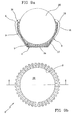
- the other type of container that is generally the preferred one (see Figs. 1 , 5 , 9 ) is on the contrary provided with a series of substantially vertical pleats arranged on the container in a regular manner.
- the pleats give a three-dimensional appearance to the side wall, that in a section of the container taken along a plane parallel to the bottom wall, is provided with a closed circular profile 11 with an undulated course similar to a sinusoid (see Fig. 4 ).
- the raised regions 5 and hollow regions 6 will extend in mutual side by side relationship along the whole extension of the side wall.
- the bottom wall 2 and side wall 3 form a cavity 7 adapted to house a foodstuff and having an upwardly facing opening in the position of normal use of the container.
- This opening defining the cavity 7 of the container is delimited by the bottom wall 2 and the side wall 3 terminating at the top with an edge 8 defining the opening contour.
- no curl-shaped reinforcing band is provided in the continuation of the side wall 3 for defining an overturned edge.
- the side wall 3 starts from the bottom wall 2 and terminates at the edge 8 so as to define the opening contour.
- the upper edge of the side wall is free and exhibits a substantially sinusoidal conformation.
- this stretch 9 has at least one curved portion 10.
- the shape of the curved portion 10 is suitable to give the side wall a substantially concave course, the concavity being turned towards the cavity 7 of the container, under use conditions of the latter.
- the curved portion can also substantially extend along the whole length of the stretch defined in section by the side wall.
- the line of the side wall in section in a vertical plane can be defined by an arc of a circumference (which situation is not shown); alternatively it can instead have a more complicated course (shown in Figs. 1 and 3 ) consisting of a first stretch 12 coming out of the bottom wall and being substantially rectilinear, then a second stretch 13 with a curvature towards the inside of cavity 7 (the curved portion 10), and finally a turned-up end portion 14, which is substantially curved as well, turned up towards the outside and delimited by edge 8.
- FIGs. 5 and 7 show a container in which the stretch 9 defining the side wall 3 in section has a first rectilinear portion 15 directly emerging from the bottom wall 2 and extending over at least two-thirds of the container height; the first portion is connected to an end portion 16 (defining said curved portion 10) encompassing the product or foodstuff 20 contained in the container in such a manner that the edge 8 substantially comes into contact with the product elastically retaining it inside the container.
- the containers 1 in accordance with the present invention can be made in such a manner that the curved portion 10 will define a rounded or convex region towards the inside of cavity 7, so that the free edge 8 defines a contour of the cavity opening 7 of smaller radial sizes than the maximum bulkiness of the product 20 contained therein.
- container 1 can elastically retain the product inside it avoiding use of viscous or sticky substances for retaining said product 20 in contact with the bottom wall 2.
- the container has a first rectilinear portion 17 emerging away from the bottom wall 2 with an inclined course relative to the vertical axis of the container.
- a second stretch 18 Connected to the first portion is a second stretch 18 which is rectilinear too and has a substantially vertical orientation under normal use conditions of the container (the first portion 17 and the second stretch 18 therefore defining a broken line in section).
- a curved end portion 19 is connected to the second stretch 18 and it is turned over towards the inside of cavity 7 in such a manner that, once again, the free edge 8 clings the foodstuff 20 contained therein.
- the container is characterised in that the side wall has a conformation with substantially convex regions adapted to encompass the product 20.
- the containers of the invention have been mainly designed for containing cakes of small sizes (as previously said, they are substantially "bun cases"), so that the bottom wall will generally be of circular shape, as shown in the accompanying drawings, and will have a diameter preferably included between 10 and 110 mm, whose preferred range will be 20 to 90 mm.
- manufacture of said bottom wall 2 (generally of round shape) is carried out, said wall having an upper surface 2a and a lower surface 2b opposite to each other (the two opposing round faces of the bottom).
- the preferred and illustrated embodiment shows said bottom and side walls 2, 3 made simultaneously in a single step from the same sheet of paper material, so that they are joined without a break (made of one piece construction by drawing).
- the step of making the side wall gives the latter such a conformation that it exhibits the aforesaid predetermined number of pleats 4 having a major orientation transverse to the bottom wall, as shown in the drawings. Still during the step of forming the side wall 3, provision is made for making said stretch 9 joining the bottom wall 2 to a contour 22 of the holding region 21 in such a manner that the stretch 9 has at least one curved portion 10a before carrying out the following working steps.
- the curved portion 10a of the side wall 3 in this step appears to be substantially convex, the convexity facing the holding region 21 of the semifinished product.
- a flat element of paper material is submitted to a drawing operation so as to define said circular bottom 2 and pleated side wall 3 that, seen in section, has a curvature "opposite" to the desired one in the final container.
- the lower surface 2b of the bottom wall 2 in the semifinished product will define a surface internal to the holding region 21, while the upper surface 2a will be turned externally, relative to said holding region.
- the production process for manufacturing said side and bottom walls therefore involves a drawing step for making the semifinished containers shown in Figs. 2 , 6 and 10 , capable of giving assurance that during the pressing step sufficient pressures are generated that are adapted to give the semifinished product itself a sufficient stiffness degree enabling it to maintain its shape.
- the side wall 3 is turned over on the opposite side relative to the bottom wall 2 so as to define the aforesaid cavity 7 having its opening facing upwards in the position of normal use of the container.
- the cavity 7 has its bottom defined by the upper surface 2a while the lower surface 2b (previously contained in the holding region 21) will be external to the container itself.
- the side wall 3 is such deformed that it moves around the perimeter of bottom 2 reaching the opposite side relative to said bottom, in the final configuration of the container.
- a product 20 that has to be contained in cavity 7 can be positioned close to the upper surface 2a of the bottom (i.e. externally of the holding region 21). Following the overturning step, the product 20 will be contained in cavity 7, being encompassed by the side wall 3.
- the invention achieves important advantages.
- the container has an optimal behaviour towards the lateral deformations.
- this side wall tends to close on the product, instead of opening.
- the side wall has such a conformation that the paper fibre has a tendency to close on the product instead of opening and falling downwards.
- the described production method appears to be of very simple accomplishment enabling manufacture of containers seemingly having very complicated shapes by means of secure and well-tested procedure steps (drawing).
- the method of the invention allows containers of paper material to be made which are provided with undercuts facing the inside of the cavity, which undercuts cannot be obtained in an alternative manner, except by use of complicated moving dies and very high pressures during the pressing step.
Description
- The present invention relates to a method of manufacturing a container made of a sheet material, preferably paper, for foodstuffs, in particular for products such as pastries, small cakes and the like.
- It is a further object of the invention to provide a production process and a packaging or wrapping-up process for a foodstuff.
- It is known that containers of paper material for foodstuffs, in particular for confectionery goods of small sizes such as pastries and the like, known in the technical field as "bun cases", generally consist of a single portion of paper material, of circular shape for example, obtained by a punching or cutting-away operation and suitably shaped so as to obtain a flat bottom wall and a flared side wall in the form of a truncated cone so as to promote formation of packets and containers suitable to be stacked up on each other.
- The bottom wall and side wall form a cavity having an opening facing upwardly in the normal use position of the container. In addition, the side wall is normally made up of a pleating formed with pleats and waves having a substantially vertical extension direction, i.e. a direction corresponding to the apothem of the truncated cone, and defining an indented upper edge.
- Generally, the bun cases are obtained starting from a flat sheet of suitable sizes, made of paper material, which is drawn by means of male-female dies capable of forming the flat bottom wall, as well as the corresponding pleats on the side wall.
- Following the drawing operation, a slight spring-back of the paper defining the side wall makes the container take its final frustoconical shape.
- In particular, by examining a section in a plane orthogonal to the bottom wall, in these containers of known type it is possible to highlight a side wall defined by a rectilinear stretch that is connected to the bottom wall.
- The above described containers that have reduced costs and are of relatively easy accomplishment, are actually very widespread in the commercial field and have been on the market for more than 90 years with a substantially unchanged shape.
- However, although this type of bun cases is commercially successful, it is not clear of some drawbacks and/or operating limits.
- First of all, it is to be pointed out that the particular frustoconical shape does not offer an important resistance to side deformations.
- This is mainly due to the fact that the side wall, taking into account how it is made (i.e. starting from a flat sheet), has some material in excess that is used for creating the pleating. In other words, following pressures on the side walls directed from the inside of the container to the outside, the paper material constituting said container tends to open and come back to its original flat state.
- It is also to be noted that at the moment the paper constituting the container becomes wet, due to the presence of a foodstuff inside it for example, the side wall itself further loses its resistance to deformations and bends reaching the flat conformation.
- In particular, it may often happens that following conservation of the foodstuff in the refrigerator (a wet place), the side wall will come back to its flat conformation, even only partly, so that replacement of the container is required before sale.
- In addition, since the container's shape has been substantially unchanged and standardised for many years, a modification of same would surely help in giving a particular new appearance to the container-cake assembly, making the whole different and aesthetically more appreciable as compared with containers of known type.
- Besides the mentioned containers, it is also known from the European document No.
EP 1253090 a container of paper material for pastries consisting of a holding structure having a bottom wall and a side wall with a rounded or convex shape, capable of encompassing a possible product contained inside it. - This document does not teach any manufacturing method for obtaining such a container.
- The French patent No.
FR 2767513 - The side wall is formed with successive pleats and has undulations disposed in a vertical orientation.
- The containers in accordance with the French document are of frustoconical shape and obtained starting from a flat sheet of paper material of suitable sizes that is drawn by means of male/female dies capable of producing a flat bottom and corresponding pleats on the side wall.
- Also known from document
GB 128187 -
US 2005/0093195 A1 discloses a process for manufacturing a container according to the preamble ofclaim 1. - While presently known are types of containers of paper material obtained from a single sheet which are different from the traditional frustoconical bun cases, no manufacturing method for obtaining these containers is however known which is of easy accomplishment and adapted to create said configurations in a simple, direct and reliable manner.
- It is in fact to be noted that convex containers have side walls with such relative inclinations to a vertical directrix that it is substantially very difficult with the traditional technologies to be able to reach sufficient pressures to enable the final shape of the product to be maintained.
- The present invention substantially aims at solving the mentioned drawbacks present in the known art.
- A first aim of the invention is to make available a production process enabling bun cases having shapes different from the frustoconical ones to be obtained in a simple and efficient manner, being able to ensure, during manufacture, that sufficient pressures are generated for maintenance of the shape even in the presence of said shaped configurations.
- Another aim of the invention is to enable manufacture of shapes different from the traditional ones.
- Finally, it is a non negligible aim of the invention to make available a production process and a packaging or wrapping-up process for the foodstuff that can be integrated with each other.
- The foregoing and further aims that will become more apparent in the progress of the following description are substantially achieved by a production process for a container of paper material designed to contain foodstuffs in accordance with the appended claims.
- Further features and advantages will become more apparent from a detailed description of a preferred but not exclusive embodiment of a production process in accordance with the invention.
- The description will be made hereinafter with reference to the accompanying drawings given by way of nonlimiting example, in which:
-
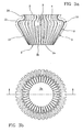
Figs. 1 ,1a ,1b ,5 ,5a, 5b ,9 ,9a and 9b show three different embodiments of a container of paper material containing a foodstuff obtained by a method in accordance with the present invention, in a perspective view, in section and from above, respectively; -
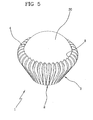
Figs. 2 ,2a ,2b ,6 ,6a, 6b ,10 ,10a and 10b show a container of paper material in a semifinished-production step, before the final manufacturing and packaging operations; -
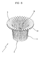
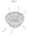
Figs. 3 ,3a ,3b ,7 ,7a, 7b , and11 ,11a, 11b show the finished container of paper material, without the product that will be contained therein; -
Fig. 4 shows a partial section of the container seen inFigs. 1 ,5 and9 , taken in a horizontal plane; -
Figs. 12a, 12b and 12c show, in a simplified section taken in a vertical plane, three successive production steps of the container seen inFig. 9 . - With reference to the drawings, the container of paper material according to the invention has been generally identified with
reference numeral 1. - It is preferably made up of a single portion of sheet of flexible material, generally paper (although with greater costs and more complicated manufacturing processes, it would be possible to contemplate the possibility of making said container using more than one sheet: a sheet for the bottom wall and one secured to the first sheet, for the side wall, for example).
- This portion of paper material cut out in the form of a circle, if the container is provided to be of circular shape for example, defines a
flat bottom wall 2 from which aside wall 3 emerges. - Since in its preferred embodiment the container is made starting from a single flat sheet of paper material, the material designed to define the
side wall 3 after the first folding appears to be in excess and therefore cannot give rise to a perfectly smooth wall. - Under this situation, there are substantially two alternative solutions.
- In a first type of containers, not shown, flattening of the side wall is carried out by pressing said wall upon itself so that the latter takes a conformation that is as much as possible smooth to the touch.
- It is apparent that, since an excess material is present, a predetermined number of irregular pleats are created on the side wall which have a major extension transverse to the bottom wall.
- Looking at this type of containers, it is possible to see that in a section of the side wall along a plane substantially parallel to the bottom wall, the profile defined by the side wall is of a substantially circular type, as much as possible close to the profile that would be defined by a perfectly smooth surface. Due to the excess material however, in this closed profile there are some regions showing overlapping material.
- The other type of container that is generally the preferred one (see
Figs. 1 ,5 ,9 ) is on the contrary provided with a series of substantially vertical pleats arranged on the container in a regular manner. - This type is represented in the accompanying figures where the side wall shows a pleating consisting of pleats or
undulations 4 having an extension substantially in a direction transverse to thebottom wall 2. - In detail as to structure, the pleats give a three-dimensional appearance to the side wall, that in a section of the container taken along a plane parallel to the bottom wall, is provided with a closed
circular profile 11 with an undulated course similar to a sinusoid (seeFig. 4 ). - The maxima of this sinusoid define a raised
region 5 on the extension surface of the side wall, while the minima constitutehollow regions 6. - Given the alternate and regular succession of maxima and minima in the section, the raised
regions 5 andhollow regions 6 will extend in mutual side by side relationship along the whole extension of the side wall. - It should be noted that the presence of a side wall having a three-dimensional extension due to the presence of undulations greatly increases the resistance of the container to stresses tending to deform the container itself crushing it.
- The
bottom wall 2 andside wall 3 form acavity 7 adapted to house a foodstuff and having an upwardly facing opening in the position of normal use of the container. - This opening defining the
cavity 7 of the container is delimited by thebottom wall 2 and theside wall 3 terminating at the top with anedge 8 defining the opening contour. - In the preferred embodiment of the present invention no curl-shaped reinforcing band is provided in the continuation of the
side wall 3 for defining an overturned edge. In other words, theside wall 3 starts from thebottom wall 2 and terminates at theedge 8 so as to define the opening contour. - In fact, as viewed from
Figs. 1 ,5 and9 , the upper edge of the side wall is free and exhibits a substantially sinusoidal conformation. - By a detailed analysis of the shape of the container being the object of the present invention, in particular with reference to
Figs. 3a ,7a and11a showing the container in side section, it is possible to see that in section along a plane substantially perpendicular to thebottom wall 2, the side wall is defined by astretch 9 joining thebottom wall 2 to the contour ofopening 8. - Advantageously, this
stretch 9 has at least onecurved portion 10. - Preferably, the shape of the
curved portion 10 is suitable to give the side wall a substantially concave course, the concavity being turned towards thecavity 7 of the container, under use conditions of the latter. - Generally, as a result of the fact that the container is made starting from a single paper sheet, the curved portion can also substantially extend along the whole length of the stretch defined in section by the side wall.
- For instance, the line of the side wall in section in a vertical plane can be defined by an arc of a circumference (which situation is not shown); alternatively it can instead have a more complicated course (shown in
Figs. 1 and3 ) consisting of afirst stretch 12 coming out of the bottom wall and being substantially rectilinear, then asecond stretch 13 with a curvature towards the inside of cavity 7 (the curved portion 10), and finally a turned-upend portion 14, which is substantially curved as well, turned up towards the outside and delimited byedge 8. - As a further possibility,
Figs. 5 and7 show a container in which thestretch 9 defining theside wall 3 in section has a firstrectilinear portion 15 directly emerging from thebottom wall 2 and extending over at least two-thirds of the container height; the first portion is connected to an end portion 16 (defining said curved portion 10) encompassing the product orfoodstuff 20 contained in the container in such a manner that theedge 8 substantially comes into contact with the product elastically retaining it inside the container. - In this connection it should be understood that generally (see all the embodiments) the
containers 1 in accordance with the present invention can be made in such a manner that thecurved portion 10 will define a rounded or convex region towards the inside ofcavity 7, so that thefree edge 8 defines a contour of thecavity opening 7 of smaller radial sizes than the maximum bulkiness of theproduct 20 contained therein. - In this manner,
container 1 can elastically retain the product inside it avoiding use of viscous or sticky substances for retaining saidproduct 20 in contact with thebottom wall 2. - In a third embodiment shown in
Figs. 9 and11 , the container has a firstrectilinear portion 17 emerging away from thebottom wall 2 with an inclined course relative to the vertical axis of the container. - Connected to the first portion is a
second stretch 18 which is rectilinear too and has a substantially vertical orientation under normal use conditions of the container (thefirst portion 17 and thesecond stretch 18 therefore defining a broken line in section). - A
curved end portion 19 is connected to thesecond stretch 18 and it is turned over towards the inside ofcavity 7 in such a manner that, once again, thefree edge 8 clings thefoodstuff 20 contained therein. - It is apparent that a multiplicity of embodiments of the
container 1 can be provided by combining said straight and curved stretches of the side wall. - By way of example only, it is herein mentioned the possibility of also making a container in accordance with the European patent No.
EP 1253090 in the name of the same Applicant. - At all events, in all the situations shown the container is characterised in that the side wall has a conformation with substantially convex regions adapted to encompass the
product 20. - The containers of the invention have been mainly designed for containing cakes of small sizes (as previously said, they are substantially "bun cases"), so that the bottom wall will generally be of circular shape, as shown in the accompanying drawings, and will have a diameter preferably included between 10 and 110 mm, whose preferred range will be 20 to 90 mm.
- It is a particular aim of the present invention to provide a production method (and/or a packaging or wrapping-up method for the foodstuff, as better shown in the following) of the previously described container of paper material.
- First of all, manufacture of said bottom wall 2 (generally of round shape) is carried out, said wall having an
upper surface 2a and alower surface 2b opposite to each other (the two opposing round faces of the bottom). - Also made is said
side wall 3 emerging from thebottom wall 2 in such a manner that with the latter it defines a holdingregion 21 the bottom surface of which is defined by saidlower surface 2b. - While theoretically it is possible to make a
bottom wall 2 and a separate side wall that are afterwards joined together, the preferred and illustrated embodiment shows said bottom andside walls - Generally, the step of making the side wall gives the latter such a conformation that it exhibits the aforesaid predetermined number of
pleats 4 having a major orientation transverse to the bottom wall, as shown in the drawings. Still during the step of forming theside wall 3, provision is made for making saidstretch 9 joining thebottom wall 2 to acontour 22 of the holdingregion 21 in such a manner that thestretch 9 has at least onecurved portion 10a before carrying out the following working steps. - In particular, the
curved portion 10a of theside wall 3 in this step appears to be substantially convex, the convexity facing the holdingregion 21 of the semifinished product. - From the operating point of view, a flat element of paper material is submitted to a drawing operation so as to define said
circular bottom 2 andpleated side wall 3 that, seen in section, has a curvature "opposite" to the desired one in the final container. - Under this situation the contour 22 (that will subsequently define edge 8) is presently turned towards the outside of the holding
region 21. - Note also that the
lower surface 2b of thebottom wall 2 in the semifinished product will define a surface internal to the holdingregion 21, while theupper surface 2a will be turned externally, relative to said holding region. - The production process for manufacturing said side and bottom walls therefore involves a drawing step for making the semifinished containers shown in
Figs. 2 ,6 and10 , capable of giving assurance that during the pressing step sufficient pressures are generated that are adapted to give the semifinished product itself a sufficient stiffness degree enabling it to maintain its shape. - For passage from the container shown in
Fig. 2 to that shown inFig. 3 (or in an equivalent manner from the container inFig. 6 to that inFig. 7 , or from the container inFig. 10 to that inFig. 11 ), theside wall 3 is turned over on the opposite side relative to thebottom wall 2 so as to define theaforesaid cavity 7 having its opening facing upwards in the position of normal use of the container. - Under this situation, the
cavity 7 has its bottom defined by theupper surface 2a while thelower surface 2b (previously contained in the holding region 21) will be external to the container itself. - The overturning steps are shown in
Figs. 12a-12b . - As can be viewed, the
side wall 3 is such deformed that it moves around the perimeter ofbottom 2 reaching the opposite side relative to said bottom, in the final configuration of the container. - By carrying out this passage, the rectilinear section stretches remain such, while the
portions 10a that in the semifinished product had a convexity facing the holdingregion 21, become now curved portions whose concavity faces thecavity 7 for housing the foodstuff, thus defining said rounded or convex structure. - It is to be pointed out that optionally, and in a manner still more advantageous, before the overturning step a
product 20 that has to be contained incavity 7 can be positioned close to theupper surface 2a of the bottom (i.e. externally of the holding region 21). Following the overturning step, theproduct 20 will be contained incavity 7, being encompassed by theside wall 3. - The invention achieves important advantages.
- First of all, for the first time after many years a container of a particular shape has been made available which is able to give a different aesthetic impact to the confectionery product that is on display.
- From a more technical point of view, due to the particular conformation of the side wall, the container has an optimal behaviour towards the lateral deformations.
- In particular, following a pressure directed from the inside to the outside of the container on the side wall, this side wall tends to close on the product, instead of opening.
- In case of a wet environment too, the side wall has such a conformation that the paper fibre has a tendency to close on the product instead of opening and falling downwards.
- On the other hand, it should be recognised that the capability of stacking up the products for storage and transport is maintained substantially unchanged without involving disadvantages relative to the known art also as regards this feature.
- The described production method appears to be of very simple accomplishment enabling manufacture of containers seemingly having very complicated shapes by means of secure and well-tested procedure steps (drawing).
- In other words, the method of the invention allows containers of paper material to be made which are provided with undercuts facing the inside of the cavity, which undercuts cannot be obtained in an alternative manner, except by use of complicated moving dies and very high pressures during the pressing step.
- In addition, due to the possibility of wrapping up or "packaging" the product during the overturning step, it is possible to produce semifinished containers while the final container will be made in the place where the foodstuff is produced, the costs for storage and transport remaining unchanged and the packaging costs being greatly reduced as packaging can be directly done in the factory where the foodstuff is produced with a single and simple operation.
Claims (9)
- A method of manufacturing a container of paper material, in particular for foodstuffs, the container comprising a sheet portion of flexible material defining a substantially flat bottom wall (2) and a side wall (3) emerging from said bottom wall (2), said bottom wall (2) and side wall (3) forming a cavity (7) with an upwardly facing opening in the normal use position of the container, the side wall (3) in the use condition of the container being confined at the lower part thereof by the bottom wall (2) and at the upper part by an edge (8) defining a contour of the cavity opening (7), the side wall (3) in section along a plane substantially perpendicular to the bottom wall (2) being defined by a stretch (9) joining said bottom wall to the opening contour, the method comprising the steps of:- making said bottom wall (2) provided with an upper surface (2a) and a lower surface (2b) opposite to each other;- making said side wall (3) emerging from the bottom wall (2) and defining, in cooperation with the bottom wall (2), a holding region (21) whose bottom is defined by said lower surface (2b),- overturning the side wall (3) on the opposite side relative to the bottom wall (2) for defining a cavity having an upwards facing opening (7) in the normal use position of the container, said cavity having a bottom defined by said upper surface (2a);characterised in that said step of making said side wall (3) comprises a sub-step of making said stretch (9) joining said bottom wall (2) to a contour (22) of the holding region (21) in such a manner that the stretch (9) has at least one curved portion (10a) before the overturning step.
- A method as claimed in the preceding claim, characterised in that the steps of making said bottom wall (2) and side wall (3) are carried out in a single simultaneous step.
- A method as claimed in anyone of the preceding claims, characterised in that the step of making said side wall (3) comprises a sub-step of forming a predetermined number of pleats (4) having a major extension substantially transverse to the bottom wall, the pleats, in a section of the side wall along a plane substantially parallel to said bottom wall (2), defining a closed profile (11) of undulated and preferably sinusoidal extension.
- A method as claimed in the preceding claim, characterised in that said step of making said stretch (9) comprises a step of making a substantially convex curved portion (10a) of the side wall (3) before the overturning step, the convexity facing the holding region (21) of the container.
- A method as claimed in anyone of the preceding claims, characterised in that said step of making the bottom wall (2) is a step of making a bottom wall (2) having a substantially circular conformation of a diameter preferably included between 10 and 110 mm.
- A method as claimed in anyone of the preceding claims, characterised in that said container is made of a paper material and defined by a suitably curved and folded single portion of a sheet.
- A method as claimed in anyone of the preceding claims, characterised in that after the overturning step the side wall (3) appears to be of a rounded or convex conformation.
- A method as claimed in anyone of the preceding claims, characterised in that before the overturning step a further step is present which consists in positioning a product to be contained in the cavity (7) at the level of the upper surface (2a) of the bottom, following the overturning step the product being contained in the cavity (7) and encompassed by the side wall (3).
- A container of paper material for foodstuffs comprising a holding body defining a holding region (22) having an opening (21), the holding body consisting of a substantially flat bottom wall (2) and a side wall (3) emerging from the bottom wall (2) and terminating with a free edge (8) defining a contour of said holding region (22), characterised in that said side wall (3) in a section along a plane substantially perpendicular to the bottom wall (2), has a stretch (9) joining said bottom wall to said opening contour provided with a substantially concave curved portion whose concavity faces the outside of the container, preferably the side wall (3) having a predetermined number of pleats (4) of a major extension substantially transverse to the bottom wall, said pleats preferably defining a closed profile of undulated preferably sinusoidal extension, in a section of the side wall (3) along a plane substantially parallel to said bottom wall (2).
Applications Claiming Priority (2)
| Application Number | Priority Date | Filing Date | Title |
|---|---|---|---|
| ITMI2009A000181A IT1392923B1 (en) | 2009-02-12 | 2009-02-12 | METHOD FOR THE REALIZATION OF A CONTAINER IN PAPER MATERIAL, PARTICULARLY FOR FOOD PRODUCTS |
| PCT/IB2010/050624 WO2010092538A1 (en) | 2009-02-12 | 2010-02-11 | Method for manufacturing a container of paper material, particularly for foodstuffs |
Publications (2)
| Publication Number | Publication Date |
|---|---|
| EP2396250A1 EP2396250A1 (en) | 2011-12-21 |
| EP2396250B1 true EP2396250B1 (en) | 2013-01-09 |
Family
ID=41203741
Family Applications (1)
| Application Number | Title | Priority Date | Filing Date |
|---|---|---|---|
| EP10708594A Active EP2396250B1 (en) | 2009-02-12 | 2010-02-11 | Method for manufacturing a container of paper material, particularly for foodstuffs. |
Country Status (8)
| Country | Link |
|---|---|
| US (1) | US8733621B2 (en) |
| EP (1) | EP2396250B1 (en) |
| BR (1) | BRPI1008475A2 (en) |
| CA (1) | CA2752475A1 (en) |
| IT (1) | IT1392923B1 (en) |
| RU (1) | RU2508239C2 (en) |
| UA (1) | UA102879C2 (en) |
| WO (1) | WO2010092538A1 (en) |
Families Citing this family (6)
| Publication number | Priority date | Publication date | Assignee | Title |
|---|---|---|---|---|
| IT1403630B1 (en) | 2011-01-14 | 2013-10-31 | Novacart Spa | MATERIAL CONTAINER IN SHEET, PARTICULARLY FOR FOOD PRODUCTS |
| IT1404243B1 (en) * | 2011-01-21 | 2013-11-15 | Soremartec Sa | PROCEDURE FOR PACKAGING A PRODUCT INTO A HERMETIC SHEET OF MATERIAL IN SHEET |
| TWI557043B (en) * | 2015-06-18 | 2016-11-11 | 南臺科技大學 | Portable flower pot stationary base |
| TWI557042B (en) * | 2015-06-18 | 2016-11-11 | 南臺科技大學 | Flower pot stationary base |
| IT201900022752A1 (en) | 2019-12-02 | 2021-06-02 | Koerber Tissue Fold S R L | A SEPARATION UNIT FOR A MACHINE FOR THE PRODUCTION OF LAMINARY PRODUCTS IN PAPER MATERIAL, IN PARTICULAR PACKAGES OF NAPKINS, TISSUES, OR SIMILAR PRODUCTS AND THEIR PRODUCTION METHOD |
| IT201900022755A1 (en) | 2019-12-02 | 2021-06-02 | Koerber Tissue Fold S R L | A SEPARATION UNIT FOR A MACHINE FOR THE PRODUCTION OF LAMINARY PRODUCTS IN PAPER MATERIAL, IN PARTICULAR PACKAGES OF NAPKINS, TISSUES, OR SIMILAR PRODUCTS AND THEIR PRODUCTION METHOD |
Family Cites Families (23)
| Publication number | Priority date | Publication date | Assignee | Title |
|---|---|---|---|---|
| US588690A (en) * | 1897-08-24 | Wrapper for fruits or vegetables | ||
| GB128187A (en) | 1918-06-11 | 1919-12-22 | Pomeon Et Ses Fils A | Improvements in Hollow Articles made from Sheets of Paper, Cardboard or other Non-metallic Material. |
| US1616570A (en) * | 1926-06-09 | 1927-02-08 | Boynton Dorothy | Ice-cream cone |
| DE526452C (en) * | 1929-07-13 | 1931-06-09 | Dentler & Maass G M B H | Device for folding in objects and producing ready-to-fill containers |
| DE555677C (en) * | 1930-08-30 | 1932-07-30 | Dentler & Maass G M B H | Machine for packing objects, which folds the viscose skin around the object like a pleated layer and provides the locking point with a label |
| US1941944A (en) * | 1932-03-14 | 1934-01-02 | Fuller S Ltd | Cup-like wrapping element for sweetmeats and the like |
| US2027296A (en) * | 1935-08-06 | 1936-01-07 | Stuart Kimberly | Baking utensil |
| DE730766C (en) * | 1938-09-06 | 1943-01-18 | Leonard Monheim Fa | Method and device for driving shaped pieces, e.g. B. Confectionery |
| US3054144A (en) * | 1959-01-23 | 1962-09-18 | American Seal Kap Corp | Apparatus for making paper containers |
| US3481175A (en) * | 1968-01-11 | 1969-12-02 | Maytag Co | Method of forming and perforating a container |
| US3512458A (en) * | 1968-06-14 | 1970-05-19 | Multicup Automation Co Inc | Method of making an adhesively joined article holding tray |
| FR2056216A5 (en) * | 1969-07-11 | 1971-05-14 | Isap Spa | |
| US4235160A (en) * | 1978-06-21 | 1980-11-25 | Brown Company | Process for making filter cups |
| US5314398A (en) * | 1984-05-22 | 1994-05-24 | Highland Supply Corporation | Flower pot or flower pot cover with base having overlapping fold some of which are connected and some of which are unconnected |
| IT220031Z2 (en) * | 1990-06-29 | 1993-06-09 | Novacart Spa | CONTAINER FOR THE COOKING AND DISTRIBUTION OF SWEETS OR FOOD IN GENERAL. |
| DE19522367A1 (en) * | 1995-06-20 | 1997-01-02 | Schubert Gerhard Gmbh | Chocolates in paper cups |
| GB9612669D0 (en) * | 1996-06-18 | 1996-08-21 | Pethick & Money Ltd | Improvements in or relating to packs for articles of merchandise |
| AU3754795A (en) | 1995-10-31 | 1997-05-22 | Hirano Shiki Co., Ltd. | Container for cake |
| FR2767513B1 (en) | 1997-08-22 | 1999-11-12 | Yoplait Sa | PACKAGING FOR FOOD PRODUCTS, PARTICULARLY FOR PASTRY AND DAIRY PRODUCTS |
| ES2214004T3 (en) * | 1999-04-23 | 2004-09-01 | Soremartec S.A. | A METHOD AND A DEVICE FOR WRAPPING A PRODUCT IN A WRAP OF LAMINARY MATERIAL AND RESPECTIVE WRAPPED PRODUCT. |
| ITMI20010812A1 (en) * | 2001-04-13 | 2002-10-13 | Novacart Spa | PREFERABLY PAPER SHEET MATERIAL CONTAINER FOR FOOD PRODUCTS, IN PARTICULAR FOR PASTRY PRODUCTS |
| NL1024308C2 (en) * | 2003-09-16 | 2005-03-18 | Voges Verpakking B V | Method for forming a package for flowers and plants, and such a package. |
| US9555594B2 (en) * | 2006-07-17 | 2017-01-31 | Dixie Consumer Products Llc | Disposable fluted paperboard plates and method of making same |
-
2009
- 2009-02-12 IT ITMI2009A000181A patent/IT1392923B1/en active
-
2010
- 2010-02-11 WO PCT/IB2010/050624 patent/WO2010092538A1/en active Application Filing
- 2010-02-11 BR BRPI1008475A patent/BRPI1008475A2/en not_active Application Discontinuation
- 2010-02-11 RU RU2011136880/12A patent/RU2508239C2/en not_active IP Right Cessation
- 2010-02-11 US US13/146,893 patent/US8733621B2/en active Active
- 2010-02-11 CA CA2752475A patent/CA2752475A1/en not_active Abandoned
- 2010-02-11 EP EP10708594A patent/EP2396250B1/en active Active
- 2010-11-02 UA UAA201109902A patent/UA102879C2/en unknown
Also Published As
| Publication number | Publication date |
|---|---|
| RU2011136880A (en) | 2013-03-20 |
| US20120043337A1 (en) | 2012-02-23 |
| BRPI1008475A2 (en) | 2016-03-08 |
| EP2396250A1 (en) | 2011-12-21 |
| RU2508239C2 (en) | 2014-02-27 |
| IT1392923B1 (en) | 2012-04-02 |
| CA2752475A1 (en) | 2010-08-19 |
| UA102879C2 (en) | 2013-08-27 |
| ITMI20090181A1 (en) | 2010-08-13 |
| US8733621B2 (en) | 2014-05-27 |
| WO2010092538A1 (en) | 2010-08-19 |
Similar Documents
| Publication | Publication Date | Title |
|---|---|---|
| EP2396250B1 (en) | Method for manufacturing a container of paper material, particularly for foodstuffs. | |
| EP2716551B1 (en) | Sealing membrane with pull-tab | |
| US6237845B1 (en) | Paper container and method for manufacturing the same | |
| CN108688968B (en) | Tamper evident plastic food container | |
| WO2006042908A1 (en) | Paper cup and method for making the same | |
| WO2008018533A1 (en) | Punch die for cardboard box with tear strip | |
| JP4725888B2 (en) | Cup-shaped container and thermoforming method thereof | |
| JP7387192B2 (en) | Peel-off firing container | |
| EP1773687A1 (en) | Beverage container insulator | |
| EP1253090B1 (en) | Container of sheet material, preferably paper, for foodstuff, in particular confectionery products | |
| JP2004067150A (en) | Paper sheet molded body | |
| EP1738891B1 (en) | Improved manfacturing method for a semi-rigid package which contains inside a thermoformed plastic protection cover | |
| WO2008018535A1 (en) | Cardboard box with tear strip | |
| EP3102037B1 (en) | A cooking mould for food products and process for realising the same | |
| EP1108651B1 (en) | Container of corrugated sheet material for foodstuff, in particular cakes | |
| KR100568560B1 (en) | A paper vessel cover | |
| JP3184340U (en) | Vertical paper drawn paper container | |
| TWI834699B (en) | Baking container | |
| KR101692223B1 (en) | Manufacturing method of paper container | |
| JP4758958B6 (en) | Die cutting of cardboard boxes with tear strips | |
| RU98098U1 (en) | VASE BOX | |
| KR200367934Y1 (en) | A paper vessel cover | |
| EP1477419A1 (en) | Covering element in paper material, particularly for containers or trays for foodstuff | |
| JP6188119B2 (en) | Mirror decoration | |
| RU36350U1 (en) | Packing with the frozen semi-finished product |
Legal Events
| Date | Code | Title | Description |
|---|---|---|---|
| PUAI | Public reference made under article 153(3) epc to a published international application that has entered the european phase |
Free format text: ORIGINAL CODE: 0009012 |
|
| 17P | Request for examination filed |
Effective date: 20110727 |
|
| AK | Designated contracting states |
Kind code of ref document: A1 Designated state(s): AT BE BG CH CY CZ DE DK EE ES FI FR GB GR HR HU IE IS IT LI LT LU LV MC MK MT NL NO PL PT RO SE SI SK SM TR |
|
| DAX | Request for extension of the european patent (deleted) | ||
| GRAP | Despatch of communication of intention to grant a patent |
Free format text: ORIGINAL CODE: EPIDOSNIGR1 |
|
| GRAS | Grant fee paid |
Free format text: ORIGINAL CODE: EPIDOSNIGR3 |
|
| GRAA | (expected) grant |
Free format text: ORIGINAL CODE: 0009210 |
|
| AK | Designated contracting states |
Kind code of ref document: B1 Designated state(s): AT BE BG CH CY CZ DE DK EE ES FI FR GB GR HR HU IE IS IT LI LT LU LV MC MK MT NL NO PL PT RO SE SI SK SM TR |
|
| REG | Reference to a national code |
Ref country code: GB Ref legal event code: FG4D |
|
| REG | Reference to a national code |
Ref country code: AT Ref legal event code: REF Ref document number: 592611 Country of ref document: AT Kind code of ref document: T Effective date: 20130115 Ref country code: CH Ref legal event code: EP |
|
| REG | Reference to a national code |
Ref country code: IE Ref legal event code: FG4D |
|
| REG | Reference to a national code |
Ref country code: DE Ref legal event code: R096 Ref document number: 602010004527 Country of ref document: DE Effective date: 20130307 |
|
| PG25 | Lapsed in a contracting state [announced via postgrant information from national office to epo] |
Ref country code: SI Free format text: LAPSE BECAUSE OF FAILURE TO SUBMIT A TRANSLATION OF THE DESCRIPTION OR TO PAY THE FEE WITHIN THE PRESCRIBED TIME-LIMIT Effective date: 20130109 |
|
| REG | Reference to a national code |
Ref country code: NL Ref legal event code: VDEP Effective date: 20130109 |
|
| REG | Reference to a national code |
Ref country code: AT Ref legal event code: MK05 Ref document number: 592611 Country of ref document: AT Kind code of ref document: T Effective date: 20130109 |
|
| REG | Reference to a national code |
Ref country code: LT Ref legal event code: MG4D |
|
| PG25 | Lapsed in a contracting state [announced via postgrant information from national office to epo] |
Ref country code: ES Free format text: LAPSE BECAUSE OF FAILURE TO SUBMIT A TRANSLATION OF THE DESCRIPTION OR TO PAY THE FEE WITHIN THE PRESCRIBED TIME-LIMIT Effective date: 20130420 Ref country code: IS Free format text: LAPSE BECAUSE OF FAILURE TO SUBMIT A TRANSLATION OF THE DESCRIPTION OR TO PAY THE FEE WITHIN THE PRESCRIBED TIME-LIMIT Effective date: 20130509 Ref country code: LT Free format text: LAPSE BECAUSE OF FAILURE TO SUBMIT A TRANSLATION OF THE DESCRIPTION OR TO PAY THE FEE WITHIN THE PRESCRIBED TIME-LIMIT Effective date: 20130109 Ref country code: BG Free format text: LAPSE BECAUSE OF FAILURE TO SUBMIT A TRANSLATION OF THE DESCRIPTION OR TO PAY THE FEE WITHIN THE PRESCRIBED TIME-LIMIT Effective date: 20130409 Ref country code: SE Free format text: LAPSE BECAUSE OF FAILURE TO SUBMIT A TRANSLATION OF THE DESCRIPTION OR TO PAY THE FEE WITHIN THE PRESCRIBED TIME-LIMIT Effective date: 20130109 Ref country code: BE Free format text: LAPSE BECAUSE OF FAILURE TO SUBMIT A TRANSLATION OF THE DESCRIPTION OR TO PAY THE FEE WITHIN THE PRESCRIBED TIME-LIMIT Effective date: 20130109 Ref country code: AT Free format text: LAPSE BECAUSE OF FAILURE TO SUBMIT A TRANSLATION OF THE DESCRIPTION OR TO PAY THE FEE WITHIN THE PRESCRIBED TIME-LIMIT Effective date: 20130109 Ref country code: NO Free format text: LAPSE BECAUSE OF FAILURE TO SUBMIT A TRANSLATION OF THE DESCRIPTION OR TO PAY THE FEE WITHIN THE PRESCRIBED TIME-LIMIT Effective date: 20130409 |
|
| PG25 | Lapsed in a contracting state [announced via postgrant information from national office to epo] |
Ref country code: GR Free format text: LAPSE BECAUSE OF FAILURE TO SUBMIT A TRANSLATION OF THE DESCRIPTION OR TO PAY THE FEE WITHIN THE PRESCRIBED TIME-LIMIT Effective date: 20130410 Ref country code: FI Free format text: LAPSE BECAUSE OF FAILURE TO SUBMIT A TRANSLATION OF THE DESCRIPTION OR TO PAY THE FEE WITHIN THE PRESCRIBED TIME-LIMIT Effective date: 20130109 Ref country code: LV Free format text: LAPSE BECAUSE OF FAILURE TO SUBMIT A TRANSLATION OF THE DESCRIPTION OR TO PAY THE FEE WITHIN THE PRESCRIBED TIME-LIMIT Effective date: 20130109 Ref country code: NL Free format text: LAPSE BECAUSE OF FAILURE TO SUBMIT A TRANSLATION OF THE DESCRIPTION OR TO PAY THE FEE WITHIN THE PRESCRIBED TIME-LIMIT Effective date: 20130109 Ref country code: PT Free format text: LAPSE BECAUSE OF FAILURE TO SUBMIT A TRANSLATION OF THE DESCRIPTION OR TO PAY THE FEE WITHIN THE PRESCRIBED TIME-LIMIT Effective date: 20130509 Ref country code: PL Free format text: LAPSE BECAUSE OF FAILURE TO SUBMIT A TRANSLATION OF THE DESCRIPTION OR TO PAY THE FEE WITHIN THE PRESCRIBED TIME-LIMIT Effective date: 20130109 |
|
| PG25 | Lapsed in a contracting state [announced via postgrant information from national office to epo] |
Ref country code: HR Free format text: LAPSE BECAUSE OF FAILURE TO SUBMIT A TRANSLATION OF THE DESCRIPTION OR TO PAY THE FEE WITHIN THE PRESCRIBED TIME-LIMIT Effective date: 20130109 Ref country code: MC Free format text: LAPSE BECAUSE OF NON-PAYMENT OF DUE FEES Effective date: 20130228 |
|
| PG25 | Lapsed in a contracting state [announced via postgrant information from national office to epo] |
Ref country code: SK Free format text: LAPSE BECAUSE OF FAILURE TO SUBMIT A TRANSLATION OF THE DESCRIPTION OR TO PAY THE FEE WITHIN THE PRESCRIBED TIME-LIMIT Effective date: 20130109 Ref country code: DK Free format text: LAPSE BECAUSE OF FAILURE TO SUBMIT A TRANSLATION OF THE DESCRIPTION OR TO PAY THE FEE WITHIN THE PRESCRIBED TIME-LIMIT Effective date: 20130109 Ref country code: RO Free format text: LAPSE BECAUSE OF FAILURE TO SUBMIT A TRANSLATION OF THE DESCRIPTION OR TO PAY THE FEE WITHIN THE PRESCRIBED TIME-LIMIT Effective date: 20130109 Ref country code: CZ Free format text: LAPSE BECAUSE OF FAILURE TO SUBMIT A TRANSLATION OF THE DESCRIPTION OR TO PAY THE FEE WITHIN THE PRESCRIBED TIME-LIMIT Effective date: 20130109 Ref country code: EE Free format text: LAPSE BECAUSE OF FAILURE TO SUBMIT A TRANSLATION OF THE DESCRIPTION OR TO PAY THE FEE WITHIN THE PRESCRIBED TIME-LIMIT Effective date: 20130109 |
|
| PLBE | No opposition filed within time limit |
Free format text: ORIGINAL CODE: 0009261 |
|
| STAA | Information on the status of an ep patent application or granted ep patent |
Free format text: STATUS: NO OPPOSITION FILED WITHIN TIME LIMIT |
|
| PG25 | Lapsed in a contracting state [announced via postgrant information from national office to epo] |
Ref country code: CY Free format text: LAPSE BECAUSE OF FAILURE TO SUBMIT A TRANSLATION OF THE DESCRIPTION OR TO PAY THE FEE WITHIN THE PRESCRIBED TIME-LIMIT Effective date: 20130109 |
|
| REG | Reference to a national code |
Ref country code: IE Ref legal event code: MM4A |
|
| 26N | No opposition filed |
Effective date: 20131010 |
|
| REG | Reference to a national code |
Ref country code: DE Ref legal event code: R097 Ref document number: 602010004527 Country of ref document: DE Effective date: 20131010 |
|
| PG25 | Lapsed in a contracting state [announced via postgrant information from national office to epo] |
Ref country code: IE Free format text: LAPSE BECAUSE OF NON-PAYMENT OF DUE FEES Effective date: 20130211 |
|
| PG25 | Lapsed in a contracting state [announced via postgrant information from national office to epo] |
Ref country code: MT Free format text: LAPSE BECAUSE OF FAILURE TO SUBMIT A TRANSLATION OF THE DESCRIPTION OR TO PAY THE FEE WITHIN THE PRESCRIBED TIME-LIMIT Effective date: 20130109 |
|
| REG | Reference to a national code |
Ref country code: CH Ref legal event code: PL |
|
| GBPC | Gb: european patent ceased through non-payment of renewal fee |
Effective date: 20140211 |
|
| PG25 | Lapsed in a contracting state [announced via postgrant information from national office to epo] |
Ref country code: LI Free format text: LAPSE BECAUSE OF NON-PAYMENT OF DUE FEES Effective date: 20140228 Ref country code: CH Free format text: LAPSE BECAUSE OF NON-PAYMENT OF DUE FEES Effective date: 20140228 |
|
| PG25 | Lapsed in a contracting state [announced via postgrant information from national office to epo] |
Ref country code: GB Free format text: LAPSE BECAUSE OF NON-PAYMENT OF DUE FEES Effective date: 20140211 |
|
| PG25 | Lapsed in a contracting state [announced via postgrant information from national office to epo] |
Ref country code: SM Free format text: LAPSE BECAUSE OF FAILURE TO SUBMIT A TRANSLATION OF THE DESCRIPTION OR TO PAY THE FEE WITHIN THE PRESCRIBED TIME-LIMIT Effective date: 20130109 |
|
| PG25 | Lapsed in a contracting state [announced via postgrant information from national office to epo] |
Ref country code: TR Free format text: LAPSE BECAUSE OF FAILURE TO SUBMIT A TRANSLATION OF THE DESCRIPTION OR TO PAY THE FEE WITHIN THE PRESCRIBED TIME-LIMIT Effective date: 20130109 |
|
| PG25 | Lapsed in a contracting state [announced via postgrant information from national office to epo] |
Ref country code: LU Free format text: LAPSE BECAUSE OF NON-PAYMENT OF DUE FEES Effective date: 20130211 Ref country code: MK Free format text: LAPSE BECAUSE OF FAILURE TO SUBMIT A TRANSLATION OF THE DESCRIPTION OR TO PAY THE FEE WITHIN THE PRESCRIBED TIME-LIMIT Effective date: 20130109 Ref country code: HU Free format text: LAPSE BECAUSE OF FAILURE TO SUBMIT A TRANSLATION OF THE DESCRIPTION OR TO PAY THE FEE WITHIN THE PRESCRIBED TIME-LIMIT; INVALID AB INITIO Effective date: 20100211 |
|
| REG | Reference to a national code |
Ref country code: FR Ref legal event code: PLFP Year of fee payment: 7 |
|
| REG | Reference to a national code |
Ref country code: FR Ref legal event code: PLFP Year of fee payment: 8 |
|
| REG | Reference to a national code |
Ref country code: FR Ref legal event code: PLFP Year of fee payment: 9 |
|
| PGFP | Annual fee paid to national office [announced via postgrant information from national office to epo] |
Ref country code: FR Payment date: 20230223 Year of fee payment: 14 |
|
| PGFP | Annual fee paid to national office [announced via postgrant information from national office to epo] |
Ref country code: IT Payment date: 20230227 Year of fee payment: 14 |
|
| PGFP | Annual fee paid to national office [announced via postgrant information from national office to epo] |
Ref country code: DE Payment date: 20240229 Year of fee payment: 15 |