EP2395887B1 - Mixing, heating and/or whipping device for preparing hot beverages - Google Patents
Mixing, heating and/or whipping device for preparing hot beverages Download PDFInfo
- Publication number
- EP2395887B1 EP2395887B1 EP10701521A EP10701521A EP2395887B1 EP 2395887 B1 EP2395887 B1 EP 2395887B1 EP 10701521 A EP10701521 A EP 10701521A EP 10701521 A EP10701521 A EP 10701521A EP 2395887 B1 EP2395887 B1 EP 2395887B1
- Authority
- EP
- European Patent Office
- Prior art keywords
- liquid
- frothed
- central body
- channel
- passage
- Prior art date
- Legal status (The legal status is an assumption and is not a legal conclusion. Google has not performed a legal analysis and makes no representation as to the accuracy of the status listed.)
- Not-in-force
Links
Images



Classifications
-
- A—HUMAN NECESSITIES
- A47—FURNITURE; DOMESTIC ARTICLES OR APPLIANCES; COFFEE MILLS; SPICE MILLS; SUCTION CLEANERS IN GENERAL
- A47J—KITCHEN EQUIPMENT; COFFEE MILLS; SPICE MILLS; APPARATUS FOR MAKING BEVERAGES
- A47J31/00—Apparatus for making beverages
- A47J31/44—Parts or details or accessories of beverage-making apparatus
-
- A—HUMAN NECESSITIES
- A47—FURNITURE; DOMESTIC ARTICLES OR APPLIANCES; COFFEE MILLS; SPICE MILLS; SUCTION CLEANERS IN GENERAL
- A47J—KITCHEN EQUIPMENT; COFFEE MILLS; SPICE MILLS; APPARATUS FOR MAKING BEVERAGES
- A47J31/00—Apparatus for making beverages
- A47J31/44—Parts or details or accessories of beverage-making apparatus
- A47J31/4489—Steam nozzles, e.g. for introducing into a milk container to heat and foam milk
-
- A—HUMAN NECESSITIES
- A47—FURNITURE; DOMESTIC ARTICLES OR APPLIANCES; COFFEE MILLS; SPICE MILLS; SUCTION CLEANERS IN GENERAL
- A47J—KITCHEN EQUIPMENT; COFFEE MILLS; SPICE MILLS; APPARATUS FOR MAKING BEVERAGES
- A47J31/00—Apparatus for making beverages
- A47J31/40—Beverage-making apparatus with dispensing means for adding a measured quantity of ingredients, e.g. coffee, water, sugar, cocoa, milk, tea
-
- A—HUMAN NECESSITIES
- A47—FURNITURE; DOMESTIC ARTICLES OR APPLIANCES; COFFEE MILLS; SPICE MILLS; SUCTION CLEANERS IN GENERAL
- A47J—KITCHEN EQUIPMENT; COFFEE MILLS; SPICE MILLS; APPARATUS FOR MAKING BEVERAGES
- A47J31/00—Apparatus for making beverages
- A47J31/44—Parts or details or accessories of beverage-making apparatus
- A47J31/4485—Nozzles dispensing heated and foamed milk, i.e. milk is sucked from a milk container, heated and foamed inside the device, and subsequently dispensed from the nozzle
Definitions
- the present invention relates to a mixing, heating and/or whipping and/or frothing device for preparing hot beverages, in particular milk.
- Such steam jet is propelled under the free surface of the beverage to be frothed and, in order to obtain correct whipping, the operator must have high manual skills in order to obtain repeatable and quality results.
- the emulsion of a liquid entails the mixing of at least two fluids in liquid phase that are not miscible.
- the mixing of fluids in the gaseous phase (steam and air) with a fluid in the liquid phase (milk) forms froth.
- the turbulence which is generated thanks to the speed of the steam flow, makes the liquid incorporate air and, together with the heating induced by the steam, the frothing and mixing of the beverage is achieved.
- the steam jet travels through a main duct at high speed in order to create a partial vacuum in the ducts for aspirating the air and the liquid to be frothed, which are connected to the main duct.
- the air and the liquid to be frothed are both aspirated and conveyed into the main duct, in which the mixing of the three fluids takes place, with the consequent whipping and mixing of the beverage.
- a drawback of the background art is that it is not always possible to obtain optimum froths, due to the inexperience of the user or to the ineffective mixing of air, liquid and steam.
- frothing devices of the known type resides in that they are not easy to clean, especially inside cavities and blind spots.
- the need to perform cleaning operations on these types of components, especially those installed on espresso coffee machines, is in fact frequent, because during use the heating and the particular type of liquid to be whipped, i.e., milk, causes the adhesion of residues which over time become increasingly harder to remove.
- the aim of the present invention is to provide a device for heating and frothing liquids, particularly milk, which is able to produce a thick and firm froth.
- an object of the present invention is to provide a device that is constructively simple and easy to clean.
- Another object of the present invention is to provide a device that is economically competitive with respect to the background art.
- the frothing, heating and/or whipping device for preparing hot beverages is generally designated by the reference numeral 1 and comprises a central body 2 detachably associated with a steam delivery tube 3 and an outer casing 4 in which the central body is inserted.
- the outer casing 4 is a substantially tubular element, preferably made of rigid plastics, which is fitted detachably over the central body 2, which is preferably made entirely of rubber-like material.
- the internal surface of the casing 4 has a shape that converges slightly toward the central axis, in the direction of the flow of the steam fed by the delivery tube 3.
- the mutual fixing between the central body 2 and the outer casing 4 is preferably obtained by interference, as shown in the enlarged-scale view of Figure 7 .
- the central body 2 can be entirely made of rubber-like material, or at least partially at the regions that provide interference and tightness with respect to the outer casing 4.
- the remaining part can be made of rigid plastics by way of bi-injection or co-molding processes.
- both the central body 2 and the outer casing 4 can be made of non-stick material.
- a possible constructive variation of the outer casing 4, not shown in the figures, can consist for example in providing such casing as two half-shells which can be mutually assembled, in order to further increase the level of accessibility by the user during cleaning.
- the central body 2 is a single longitudinally elongated contoured insert, with a tubular end portion 2a arranged at the radially wider part of the insert 2, and forms the region of detachable connection to the delivery tube 3 and to the casing 4.
- the delivery tube 3 can be inserted by interference in the axial cavity of the central body 2, which forms a main passage duct 5 for steam, which is shown in Figures 4 and 8 .
- the main steam duct 5 ends with a nozzle 6 which is adapted to increase the speed of the steam and to inject it into a downstream channel 11 formed between the central body 2 and the casing 4.
- the central body 2 has, downstream of the tubular portion 2a, a plurality of longitudinal grooves which are adapted to form passage channels 7 and 8 for air and for the liquid to be frothed in order to mix it with the air and the steam.
- liquid passage channels 7 are formed by the grooves between two longitudinal ribs 7a and 7b which extend along the central body 2 on the opposite side with respect to the end portion 2a and form the rising channels of the liquid to be frothed in combination with the inner surface of the casing 4.
- the ribs 7a and 7b can be sized radially so as to remain in contact with the inner surface of the casing 4, so as to isolate the liquid passage channels 7 from the outflow channel of the emulsion 11.
- the latter is arranged downstream of the nozzle 6, in the direction of the steam, and is formed between the two ribs 7a and 7b and the inner surface of the casing 4.
- an air intake channel 8 which is formed by a longitudinal groove provided along an outer surface of the central body 2 which does not belong to the ribs 7a and 7b and remains in contact with the inner surface of the casing 4. This allows to keep the air intake channel 8 separate and isolated with respect to the outflow channel of the preparation 11.
- the air intake channel 8 is extended starting from the upper edge of the end portion 2a, so as to be able to be connected to the outside environment, and along much of the longitudinal extension of the central body 2, leading into both rising channels 7.
- the intake channel 8 ends with a bifurcation, for example T-shaped, so as to allow connection only to the liquid passage channels 7, forming a first mixing region 9.
- a mixture is formed which is composed of the air and the liquid to be frothed which arrive by Venturi effect respectively from the intake channel 8 and from the liquid passage channels 7.
- a second mixing region 10 which is separate and distinct from the first mixing region 9, is further provided proximate to the nozzle 6 and downstream of it, by means of suitable recesses on the upper part of the ribs 7a and 7b, in order to connect only the liquid passage channels 7 to the frothed liquid outflow channel 11.
- the second mixing region 10 is arranged at a substantially central portion 2b of the central body 2.
- the air-liquid mixture formed in the first mixing region 9 converges in the second mixing region 10 located proximate to the nozzle 6 in order to generate the air-liquid-steam mixture as a consequence of the interaction with the steam injected into the channel 11 through the nozzle 6.
- the end part 2c of the central body 2 protrudes with respect to the outer casing 4 in order to ensure circulation of the fluids, even if the device 1 is placed in contact with the walls or bottom of the vessel in which the process takes place. In this manner, the inlets and outlets are not blocked, and if the unit slips off the delivery tube 3 during the operation for cleaning the assembly, it becomes possible to push the central body 2 while holding the outer casing 4, allowing to slide off easily the central body 2 with an operation that can be performed with a single hand.
- the air enters by Venturi effect from the intake channel 8 and mixes with the liquid in the first mixing region 9, reducing the local density of the mixture and helping its rise along the channels 7 for an equal partial vacuum and cross-section of the duct.
- the rising speed is determined by the result of the balance among the partial vacuum that is created, the cross-sections of the channels, the specific gravity of the liquid and its viscosity.
- the mixture After transit in this first stage, the mixture arrives proximate to the nozzle 6, i.e., in the second mixing region 10. By meeting the flow of steam, the mixture is heated and whipped and is propelled toward the outflow channel 11 of the preparation, which is located downward.
- the frothing, heating and/or whipping device for preparing hot beverages according to the present invention, fully achieves the intended aim and objects, since it allows to achieve the whipping of a beverage effectively, by means of an air-liquid pre-mixing which precedes the mixing with the steam, thus obtaining a froth of excellent quality.
- Another advantage of the device according to the present invention consists in that the central body, being provided monolithically, can be easily disassembled from the casing with a single operation, i.e., simply by sliding off the casing.
- the central body without the outer casing, can be cleaned with a moist cloth either by leaving it assembled on the steam delivery tube or by sliding it off such tube and cleaning it separately, even in a dishwasher.
- a further advantage of the device according to the invention consists in that the outer casing can be cleaned internally because there are no recesses and it is completely smooth.
- frothing, heating and/or whipping device for preparing hot beverages is susceptible of numerous modifications and variations, all of which are within the scope of the appended claims.
- the materials used may be any according to requirements and to the state of the art.
Landscapes
- Engineering & Computer Science (AREA)
- Food Science & Technology (AREA)
- Apparatus For Making Beverages (AREA)
- Food-Manufacturing Devices (AREA)
- Beverage Vending Machines With Cups, And Gas Or Electricity Vending Machines (AREA)
- Vending Machines For Individual Products (AREA)
- Nozzles (AREA)
Description
- The present invention relates to a mixing, heating and/or whipping and/or frothing device for preparing hot beverages, in particular milk.
- In machines for preparing coffee or the like it is known to froth, whip a liquid by using a jet of steam which is conveyed by means of a tube and flows out from a nozzle, to be used for preparing hot beverages such as for example the so-called "cappuccino".
- Such steam jet is propelled under the free surface of the beverage to be frothed and, in order to obtain correct whipping, the operator must have high manual skills in order to obtain repeatable and quality results.
- For this reason, accessories known in the jargon as "cappuccinatori" (frothers) have been devised which are designed to be coupled to a steam delivery tube, which make the whipping easier by providing inside them an organized fluid dynamics, in order to make the result independent of the user's skill. Sometimes such accessories known in the jargon as frothers, are incorrectly termed "emulsifiers", although this term does not rigorously reflect the action performed by the accessory on the beverage to be frothed.
- As is known, the emulsion of a liquid entails the mixing of at least two fluids in liquid phase that are not miscible. In this particular case, the mixing of fluids in the gaseous phase (steam and air) with a fluid in the liquid phase (milk) forms froth. More precisely, the turbulence, which is generated thanks to the speed of the steam flow, makes the liquid incorporate air and, together with the heating induced by the steam, the frothing and mixing of the beverage is achieved.
- In particular, it is known to use devices which, by way of a plurality of passage channels which are parallel to the steam jet, allow to aspirate air and the liquid to be whipped by making them converge in a mixing region, in which the steam jet converges as well. The channels can be separated from each other, so that each one conveys a respective flow (air, liquid or steam) in a single mixing point at the steam nozzle.
- This process is allowed by the Venturi effect that is created within the device. More precisely, the steam jet travels through a main duct at high speed in order to create a partial vacuum in the ducts for aspirating the air and the liquid to be frothed, which are connected to the main duct.
- In this manner, the air and the liquid to be frothed are both aspirated and conveyed into the main duct, in which the mixing of the three fluids takes place, with the consequent whipping and mixing of the beverage.
- A drawback of the background art is that it is not always possible to obtain optimum froths, due to the inexperience of the user or to the ineffective mixing of air, liquid and steam.
- Another drawback of frothing devices of the known type resides in that they are not easy to clean, especially inside cavities and blind spots. The need to perform cleaning operations on these types of components, especially those installed on espresso coffee machines, is in fact frequent, because during use the heating and the particular type of liquid to be whipped, i.e., milk, causes the adhesion of residues which over time become increasingly harder to remove.
- Moreover, known frothing devices have a large number of components, which cause the disassembly operations that precede cleaning to be laborious. Document
US2008/0053314 discloses a frothing device. - The aim of the present invention is to provide a device for heating and frothing liquids, particularly milk, which is able to produce a thick and firm froth.
- Within this aim, an object of the present invention is to provide a device that is constructively simple and easy to clean.
- Another object of the present invention is to provide a device that is economically competitive with respect to the background art.
- This aim and these and other objects that will become better apparent hereinafter are achieved by a frothing, heating and/or whipping device according to claim 1.
- Further characteristics and advantages of the invention will become better apparent from the description of a preferred but not exclusive embodiment of a frothing, heating and/or whipping device for preparing beverages, according to the invention, illustrated by way of non-limiting example in the accompanying drawings, wherein:
-
Figure 1 is a perspective view of a frothing, heating and/or whipping device for preparing hot beverages according to one embodiment of the invention; -
Figure 2 is an exploded perspective view of the device shown inFigure 1 ; -
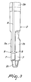
Figure 3 is a perspective view of the central body of the device shown inFigure 1 ; -
Figure 4 is an axial sectional view of the device shown inFigure 1 ; -
Figure 5 is a sectional view of the device shown inFigure 4 , taken along the line V-V; -
Figure 6 is a sectional view of the device shown inFigure 4 , taken along the line VI-VI; -
Figure 7 is an enlarged-scale view of a detail of the device shown inFigure 4 ; -
Figure 8 is a sectional view of the device shown inFigure 1 , taken along a longitudinal plane which is perpendicular to the sectional plane ofFigure 4 . - With reference to the figures, the frothing, heating and/or whipping device for preparing hot beverages, also referenced hereinafter as frother, is generally designated by the reference numeral 1 and comprises a
central body 2 detachably associated with asteam delivery tube 3 and anouter casing 4 in which the central body is inserted. - More particularly, the
outer casing 4 is a substantially tubular element, preferably made of rigid plastics, which is fitted detachably over thecentral body 2, which is preferably made entirely of rubber-like material. The internal surface of thecasing 4 has a shape that converges slightly toward the central axis, in the direction of the flow of the steam fed by thedelivery tube 3. - The mutual fixing between the
central body 2 and theouter casing 4 is preferably obtained by interference, as shown in the enlarged-scale view ofFigure 7 . - In this manner the hydraulic seal between the two components is provided.
- In order to facilitate said assembly by interference and ensure hydraulic tightness, the
central body 2 can be entirely made of rubber-like material, or at least partially at the regions that provide interference and tightness with respect to theouter casing 4. - If the
central body 2 is partially made of rubber-like material, the remaining part can be made of rigid plastics by way of bi-injection or co-molding processes. - In order to further facilitate the cleaning operations, both the
central body 2 and theouter casing 4 can be made of non-stick material. - A possible constructive variation of the
outer casing 4, not shown in the figures, can consist for example in providing such casing as two half-shells which can be mutually assembled, in order to further increase the level of accessibility by the user during cleaning. - The
central body 2 is a single longitudinally elongated contoured insert, with atubular end portion 2a arranged at the radially wider part of theinsert 2, and forms the region of detachable connection to thedelivery tube 3 and to thecasing 4. - The
delivery tube 3 can be inserted by interference in the axial cavity of thecentral body 2, which forms amain passage duct 5 for steam, which is shown inFigures 4 and8 . - The
main steam duct 5 ends with anozzle 6 which is adapted to increase the speed of the steam and to inject it into adownstream channel 11 formed between thecentral body 2 and thecasing 4. - Moreover, the
central body 2 has, downstream of thetubular portion 2a, a plurality of longitudinal grooves which are adapted to formpassage channels - More precisely,
liquid passage channels 7 are formed by the grooves between twolongitudinal ribs central body 2 on the opposite side with respect to theend portion 2a and form the rising channels of the liquid to be frothed in combination with the inner surface of thecasing 4. - The
ribs casing 4, so as to isolate theliquid passage channels 7 from the outflow channel of theemulsion 11. The latter is arranged downstream of thenozzle 6, in the direction of the steam, and is formed between the tworibs casing 4. - Between the two
liquid passage channels 7 there is anair intake channel 8, which is formed by a longitudinal groove provided along an outer surface of thecentral body 2 which does not belong to theribs casing 4. This allows to keep theair intake channel 8 separate and isolated with respect to the outflow channel of thepreparation 11. - The
air intake channel 8 is extended starting from the upper edge of theend portion 2a, so as to be able to be connected to the outside environment, and along much of the longitudinal extension of thecentral body 2, leading into both risingchannels 7. - In particular, the
intake channel 8 ends with a bifurcation, for example T-shaped, so as to allow connection only to theliquid passage channels 7, forming afirst mixing region 9. In thisfirst mixing region 9, during operation, a mixture is formed which is composed of the air and the liquid to be frothed which arrive by Venturi effect respectively from theintake channel 8 and from theliquid passage channels 7. - A
second mixing region 10, which is separate and distinct from thefirst mixing region 9, is further provided proximate to thenozzle 6 and downstream of it, by means of suitable recesses on the upper part of theribs liquid passage channels 7 to the frothedliquid outflow channel 11. Preferably, thesecond mixing region 10 is arranged at a substantiallycentral portion 2b of thecentral body 2. - In this manner, there are two different regions and, therefore, two mixing stages arranged along the device 1.
- As described in greater detail hereinafter, during operation the air-liquid mixture formed in the
first mixing region 9 converges in thesecond mixing region 10 located proximate to thenozzle 6 in order to generate the air-liquid-steam mixture as a consequence of the interaction with the steam injected into thechannel 11 through thenozzle 6. - As shown in the figures, the
end part 2c of thecentral body 2 protrudes with respect to theouter casing 4 in order to ensure circulation of the fluids, even if the device 1 is placed in contact with the walls or bottom of the vessel in which the process takes place. In this manner, the inlets and outlets are not blocked, and if the unit slips off thedelivery tube 3 during the operation for cleaning the assembly, it becomes possible to push thecentral body 2 while holding theouter casing 4, allowing to slide off easily thecentral body 2 with an operation that can be performed with a single hand. - Of course, for correct operation of the device 1 part of the
outer casing 4 also has to be immersed in the beverage. - In fact, if the air were allowed to enter through the rising
channels 7 from thepart 2c, the optimum composition of the mixture would be compromised. - Operation of the device 1 according to the present invention is directly derivable from what has been described.
- In particular, it should be stressed that the steam jet that exits from the
nozzle 6 is directed toward theoutflow channel 11 of the preparation placed in front and creates an internal partial vacuum, which draws the liquid to be frothed from theliquid passage channels 7. - The air enters by Venturi effect from the
intake channel 8 and mixes with the liquid in thefirst mixing region 9, reducing the local density of the mixture and helping its rise along thechannels 7 for an equal partial vacuum and cross-section of the duct. - More precisely, the rising speed is determined by the result of the balance among the partial vacuum that is created, the cross-sections of the channels, the specific gravity of the liquid and its viscosity.
- After transit in this first stage, the mixture arrives proximate to the
nozzle 6, i.e., in thesecond mixing region 10. By meeting the flow of steam, the mixture is heated and whipped and is propelled toward theoutflow channel 11 of the preparation, which is located downward. - In other words, the operation is composed of two separate stages, provided respectively by a mixing of the liquid and of the air in a
first mixing region 9 and by a whipping of the air-liquid mixture in asecond mixing region 10, in a point located proximate to the steam jet. - In practice it has been found that the frothing, heating and/or whipping device for preparing hot beverages, according to the present invention, fully achieves the intended aim and objects, since it allows to achieve the whipping of a beverage effectively, by means of an air-liquid pre-mixing which precedes the mixing with the steam, thus obtaining a froth of excellent quality.
- Another advantage of the device according to the present invention consists in that the central body, being provided monolithically, can be easily disassembled from the casing with a single operation, i.e., simply by sliding off the casing.
- Moreover, the central body, without the outer casing, can be cleaned with a moist cloth either by leaving it assembled on the steam delivery tube or by sliding it off such tube and cleaning it separately, even in a dishwasher. This is possible because the fluid passage channels necessary for the operation of the device are obtained mainly from the surface of the central body and become complete only when the outer casing is assembled.
- A further advantage of the device according to the invention consists in that the outer casing can be cleaned internally because there are no recesses and it is completely smooth.
- The frothing, heating and/or whipping device for preparing hot beverages, according to the present invention, is susceptible of numerous modifications and variations, all of which are within the scope of the appended claims.
- Moreover, all the details may be replaced with other technically equivalent elements.
- In practice, the materials used, so long as they are compatible with the specific use, as well as the contingent shapes and dimensions, may be any according to requirements and to the state of the art.
- Where technical features mentioned in any claim are followed by reference signs, those reference signs have been included for the sole purpose of increasing the intelligibility of the claims and accordingly such reference signs do not have any limiting effect on the interpretation of each element identified by way of example by such reference signs.
Claims (10)
- A frothing, heating and/or whipping device for preparing hot beverages, comprising a central body (2) detachably associable with a steam delivery tube (3) and an outer casing (4) which fits over said central body (2), between said central body (2) and said casing (4) there being at least one channel (7) for the passage of the liquid to be frothed, an air intake channel (8) and an outflow channel (11) for the frothed liquid, wherein it comprises at least two spatially separated mixing regions (9, 10), a first one (9) of said mixing regions being provided in a meeting point between said at least one channel (7) for the passage of the liquid to be frothed and the air intake channel (8), in order to form a first mixture composed of the air and the liquid to be frothed, a second one (10) of said mixing regions being provided in a meeting point between said at least one liquid passage channel (7) and said outflow channel (11) for the frothed liquid, said second mixing region (10) being arranged so as to mix said first mixture with the steam that arrives from said delivery tube (3), characterized in that said device comprises a plurality of longitudinal grooves which are adapted to form said at least one channel (7) for the passage of the liquid to be frothed, said air intake channel (8) and said outflow channel (11) for the frothed liquid.
- The device according to claim 1, characterized in that said central body (2) is a substantially longitudinally elongated contoured insert, which has a substantially tubular end portion (2a) which can be connected to said delivery tube (3) in order to form a main duct (5) for the inflow of said steam.
- The device according to one or more of the preceding claims, characterized in that between the passage channels (7) for the liquid to be frothed there is located said at least one air intake channel (8), which extends starting from the upper edge of the end portion (2a), so as to be able to be connected to the outside environment, and for much of the longitudinal extension of the central body (2), leading out into said at least one passage channel (7) for the liquid to be frothed.
- The device according to claim 3, comprising two of said passage channels (7) for the liquid to be frothed, said air intake channel comprising a bifurcation for connecting to both of said passage channels for the liquid to be frothed, said outflow channel (11) for the frothed liquid being connected, at a substantially central portion (2b) of said central body (2), to said two passage channels (7) for the liquid to be frothed, a nozzle (6) for injecting the steam that arrives from said main duct (5) and said second mixing region (10) being provided in the intersection between said rising channels (7) and said outflow channel (11) for the frothed liquid.
- The device according to one or more of the preceding claims, characterized in that said outer casing (4) is a substantially tubular element and is fitted detachably over said central body (2) so that its inner surface (4a) delimits radially said passage channels (7) for the liquid to be frothed, said outflow channel (11) and said intake channel (8), said central body (2) being fixed to said outer casing (4) by interference.
- The device according to one or more of the preceding claims, characterized in that said central body (2) is entirely made of rubber-like material.
- The device according to one or more of the preceding claims 1 to 5, characterized in that said central body (2) is partly made of rubber-like material and rigid plastics by means of bi-injection or co-molding processes, said rubber-like material being arranged at the regions where said central body (2) interferes and forms a seal with said outer casing (4).
- The device according to one or more of the preceding claims, characterized in that said central body (2) is made of non-stick material.
- The device according to one or more of the preceding claims, characterized in that said central body (2) is provided monolithically.
- The device according to one or more of the preceding claims, characterized in that said outer casing (4) is made of plastics or of non-stick material.
Applications Claiming Priority (2)
| Application Number | Priority Date | Filing Date | Title |
|---|---|---|---|
| ITMI2009A000199A IT1392927B1 (en) | 2009-02-16 | 2009-02-16 | MIXER, HEATER AND / OR FITTING DEVICE FOR THE PREPARATION OF HOT DRINKS. |
| PCT/EP2010/050877 WO2010091948A1 (en) | 2009-02-16 | 2010-01-26 | Mixing, heating and/or whipping device for preparing hot beverages |
Publications (2)
| Publication Number | Publication Date |
|---|---|
| EP2395887A1 EP2395887A1 (en) | 2011-12-21 |
| EP2395887B1 true EP2395887B1 (en) | 2012-10-31 |
Family
ID=41278157
Family Applications (1)
| Application Number | Title | Priority Date | Filing Date |
|---|---|---|---|
| EP10701521A Not-in-force EP2395887B1 (en) | 2009-02-16 | 2010-01-26 | Mixing, heating and/or whipping device for preparing hot beverages |
Country Status (10)
| Country | Link |
|---|---|
| US (1) | US8935978B2 (en) |
| EP (1) | EP2395887B1 (en) |
| JP (1) | JP5542845B2 (en) |
| KR (1) | KR20110127665A (en) |
| CN (1) | CN102316776B (en) |
| CA (1) | CA2751008A1 (en) |
| IT (1) | IT1392927B1 (en) |
| RU (1) | RU2531713C2 (en) |
| TW (1) | TW201036582A (en) |
| WO (1) | WO2010091948A1 (en) |
Cited By (2)
| Publication number | Priority date | Publication date | Assignee | Title |
|---|---|---|---|---|
| CN107049030A (en) * | 2017-04-10 | 2017-08-18 | 芜湖艾尔达科技有限责任公司 | A kind of foam coffee machine and prepare foam coffee method |
| EP4573986A1 (en) * | 2023-12-21 | 2025-06-25 | Versuni Holding B.V. | Kitchen mixing device and beverage machine comprising the same |
Families Citing this family (14)
| Publication number | Priority date | Publication date | Assignee | Title |
|---|---|---|---|---|
| JP6464093B2 (en) * | 2012-12-04 | 2019-02-06 | コーニンクレッカ フィリップス エヌ ヴェKoninklijke Philips N.V. | Jug and beverage production system for beverage preparation |
| JP6383741B2 (en) * | 2013-03-11 | 2018-08-29 | コーニンクレッカ フィリップス エヌ ヴェKoninklijke Philips N.V. | Liquid frothing equipment |
| CN103284601B (en) * | 2013-06-21 | 2016-08-31 | 熊兴剑 | Frothing milk machine |
| ES2572256T3 (en) * | 2014-02-07 | 2016-05-31 | Gruppo Cimbali Spa | A device for heating a quantity of liquid, in particular milk, in a container |
| WO2015173113A1 (en) * | 2014-05-13 | 2015-11-19 | Nestec S.A. | Beverage preparation device for preparation of a cooled and foamed beverage |
| CN104068751B (en) * | 2014-06-04 | 2017-02-22 | 宁波全景电器技术有限公司 | Foaming steam rod |
| JP6696914B2 (en) | 2014-06-25 | 2020-05-20 | ソシエテ・デ・プロデュイ・ネスレ・エス・アー | Disposable whipping device |
| CA2948736C (en) * | 2014-06-25 | 2022-08-02 | Nestec S.A. | Pumping and foaming device |
| DE102014216498A1 (en) * | 2014-08-20 | 2016-02-25 | BSH Hausgeräte GmbH | Milchschaumdüse |
| PT3042593T (en) * | 2015-01-09 | 2018-06-15 | Jura Elektroapparate Ag | Drinks outlet for a beverage preparation machine |
| GB2579086B (en) * | 2018-11-20 | 2022-11-16 | Douwe Egberts Bv | Frothing device and method thereof |
| CN109222659B (en) * | 2018-11-23 | 2024-06-14 | 新乐华家用电器(深圳)有限公司 | A milk frother |
| IT202100003017A1 (en) * | 2021-02-11 | 2022-08-11 | De Longhi Appliances Srl | MILK FROTHER WITH IMPROVED EASE OF ACCESS TO ITS INTERNAL PARTS FOR CLEANING |
| IT202200024045A1 (en) * | 2022-11-23 | 2024-05-23 | Angelo Sala | System for regulating and optimising the performance of steam delivery from a steam wand of an espresso machine |
Family Cites Families (9)
| Publication number | Priority date | Publication date | Assignee | Title |
|---|---|---|---|---|
| IT1198946B (en) * | 1984-10-26 | 1988-12-21 | Fulmine Srl | DEVICE FOR HEATING AND EMULSION OF MILK IN SPECIES FOR THE PREPARATION OF THE SO-CALLED CAPPUCCINO |
| IT1235868B (en) * | 1988-10-20 | 1992-11-23 | Fregnan Florindo Costruzioni M | CONVENTION FOR MOUNTING THE MILK SUITABLE IN CONNECTION WITH THE TRADITIONAL SPEED EROGAVAPORE OF A COFFEE MACHINE ESPRESSO FOR THE PREPARATION OF THE SO-CALLED CAPPUCCINO ITALIAN |
| DE4220986A1 (en) | 1992-06-26 | 1994-01-05 | Gotthard Dipl Ing Mahlich | Device for preparing milk foam for cappuccino |
| DE60119588T2 (en) * | 2001-07-11 | 2006-10-26 | Spidem S.P.A. | Device for heating and emulsifying liquids, in particular drinks |
| US6786138B2 (en) * | 2002-01-16 | 2004-09-07 | Boyd Coffee Company | Device for preparing milk froth for cappuccino |
| US6644177B1 (en) * | 2002-11-18 | 2003-11-11 | Lundar Electric Industrial Co., Ltd. | Milk foaming structure adapted to a coffee maker |
| ITMI20040213A1 (en) * | 2004-02-10 | 2004-05-10 | Tecnola S N C Di Sanna Massimo | DEVICE TO EMULSATE MILK AND AIR |
| DE102004025037A1 (en) * | 2004-05-18 | 2005-12-08 | Eimer, Klaus, Dipl.-Ing. | Milk foaming device for espresso machines has steam pipe and supply pipe which are either provided separately or are integrated to each other |
| ITMI20061469A1 (en) * | 2006-07-26 | 2008-01-27 | De Longhi Spa | DEVICE FOR THE TRAINING OF SC HIUMA IN A MILK BASED DRINK |
-
2009
- 2009-02-16 IT ITMI2009A000199A patent/IT1392927B1/en active
-
2010
- 2010-01-26 US US13/201,706 patent/US8935978B2/en not_active Expired - Fee Related
- 2010-01-26 KR KR1020117019663A patent/KR20110127665A/en not_active Withdrawn
- 2010-01-26 CA CA2751008A patent/CA2751008A1/en not_active Abandoned
- 2010-01-26 RU RU2011138009/12A patent/RU2531713C2/en not_active IP Right Cessation
- 2010-01-26 WO PCT/EP2010/050877 patent/WO2010091948A1/en not_active Ceased
- 2010-01-26 JP JP2011549505A patent/JP5542845B2/en not_active Expired - Fee Related
- 2010-01-26 EP EP10701521A patent/EP2395887B1/en not_active Not-in-force
- 2010-01-26 CN CN201080008653.4A patent/CN102316776B/en not_active Expired - Fee Related
- 2010-02-12 TW TW099104897A patent/TW201036582A/en unknown
Cited By (3)
| Publication number | Priority date | Publication date | Assignee | Title |
|---|---|---|---|---|
| CN107049030A (en) * | 2017-04-10 | 2017-08-18 | 芜湖艾尔达科技有限责任公司 | A kind of foam coffee machine and prepare foam coffee method |
| EP4573986A1 (en) * | 2023-12-21 | 2025-06-25 | Versuni Holding B.V. | Kitchen mixing device and beverage machine comprising the same |
| WO2025133342A1 (en) | 2023-12-21 | 2025-06-26 | Versuni Holding B.V. | Kitchen mixing device and beverage machine comprising the same |
Also Published As
| Publication number | Publication date |
|---|---|
| WO2010091948A1 (en) | 2010-08-19 |
| RU2011138009A (en) | 2013-03-27 |
| HK1162893A1 (en) | 2012-09-07 |
| TW201036582A (en) | 2010-10-16 |
| JP2012517834A (en) | 2012-08-09 |
| EP2395887A1 (en) | 2011-12-21 |
| IT1392927B1 (en) | 2012-04-02 |
| RU2531713C2 (en) | 2014-10-27 |
| CN102316776B (en) | 2014-06-11 |
| ITMI20090199A1 (en) | 2010-08-17 |
| JP5542845B2 (en) | 2014-07-09 |
| CN102316776A (en) | 2012-01-11 |
| CA2751008A1 (en) | 2010-08-19 |
| US20110297007A1 (en) | 2011-12-08 |
| KR20110127665A (en) | 2011-11-25 |
| US8935978B2 (en) | 2015-01-20 |
Similar Documents
| Publication | Publication Date | Title |
|---|---|---|
| US8935978B2 (en) | Mixing, heating and/or whipping device for preparing hot beverages | |
| US20130160657A1 (en) | Coffee/Espresso Machine with a Milk Froth Generating Device for the Preparation of Cappuccino | |
| US5862740A (en) | Device for frothing and heating liquids, such as milk and the like, provided with longitudinal channels for suction of the liquid-frothing air | |
| US6840163B2 (en) | Automatic device for heating and frothing a liquid, in particular milk | |
| JP6336076B2 (en) | Beverage whipping device and jug having this device | |
| JP2017522956A (en) | Machine for putting beverages containing whipped milk, especially cappuccino or latte macchiato | |
| ES2961363T3 (en) | Output device for a milk frothing device | |
| BRPI1106278A2 (en) | electric beverage preparation machine | |
| US20240049906A1 (en) | Frothing head for heating and whipping milk | |
| EP2721980A1 (en) | Device for the preparation of an emulsified beverage | |
| EP4262490B1 (en) | Milk frother with improved access to inner parts thereof for cleaning | |
| JP2021500100A (en) | Beverage vending machine | |
| HK1162893B (en) | Mixing, heating and/or whipping device for preparing hot beverages | |
| CN113226127B (en) | Foaming device and method thereof | |
| WO2023208715A1 (en) | Froth wand and attachments therefor | |
| KR20260069734A (en) | Kitchen mixing device and beverage machine including the same | |
| HK1225244A1 (en) | Milk frothing device | |
| ITRM20090568A1 (en) | MILK-STEAM MIXING DEVICE. | |
| RU2021115906A (en) | Foaming device and method of using the same | |
| HK1225243A1 (en) | Milk frothing device, beverage preparation system and machine for preparing beverages |
Legal Events
| Date | Code | Title | Description |
|---|---|---|---|
| PUAI | Public reference made under article 153(3) epc to a published international application that has entered the european phase |
Free format text: ORIGINAL CODE: 0009012 |
|
| 17P | Request for examination filed |
Effective date: 20110714 |
|
| AK | Designated contracting states |
Kind code of ref document: A1 Designated state(s): AT BE BG CH CY CZ DE DK EE ES FI FR GB GR HR HU IE IS IT LI LT LU LV MC MK MT NL NO PL PT RO SE SI SK SM TR |
|
| GRAP | Despatch of communication of intention to grant a patent |
Free format text: ORIGINAL CODE: EPIDOSNIGR1 |
|
| DAX | Request for extension of the european patent (deleted) | ||
| REG | Reference to a national code |
Ref country code: HK Ref legal event code: DE Ref document number: 1162893 Country of ref document: HK |
|
| GRAS | Grant fee paid |
Free format text: ORIGINAL CODE: EPIDOSNIGR3 |
|
| GRAA | (expected) grant |
Free format text: ORIGINAL CODE: 0009210 |
|
| AK | Designated contracting states |
Kind code of ref document: B1 Designated state(s): AT BE BG CH CY CZ DE DK EE ES FI FR GB GR HR HU IE IS IT LI LT LU LV MC MK MT NL NO PL PT RO SE SI SK SM TR |
|
| REG | Reference to a national code |
Ref country code: GB Ref legal event code: FG4D Ref country code: CH Ref legal event code: EP |
|
| REG | Reference to a national code |
Ref country code: AT Ref legal event code: REF Ref document number: 581536 Country of ref document: AT Kind code of ref document: T Effective date: 20121115 |
|
| REG | Reference to a national code |
Ref country code: IE Ref legal event code: FG4D |
|
| REG | Reference to a national code |
Ref country code: DE Ref legal event code: R096 Ref document number: 602010003444 Country of ref document: DE Effective date: 20121227 |
|
| REG | Reference to a national code |
Ref country code: NL Ref legal event code: T3 |
|
| REG | Reference to a national code |
Ref country code: CH Ref legal event code: NV Representative=s name: PATENTANWAELTE SCHAAD, BALASS, MENZL AND PARTN, CH |
|
| REG | Reference to a national code |
Ref country code: CH Ref legal event code: NV Representative=s name: PATENTANWAELTE SCHAAD, BALASS, MENZL AND PARTN, CH |
|
| REG | Reference to a national code |
Ref country code: AT Ref legal event code: MK05 Ref document number: 581536 Country of ref document: AT Kind code of ref document: T Effective date: 20121031 |
|
| REG | Reference to a national code |
Ref country code: LT Ref legal event code: MG4D |
|
| REG | Reference to a national code |
Ref country code: GR Ref legal event code: EP Ref document number: 20120402898 Country of ref document: GR Effective date: 20130205 |
|
| PG25 | Lapsed in a contracting state [announced via postgrant information from national office to epo] |
Ref country code: FI Free format text: LAPSE BECAUSE OF FAILURE TO SUBMIT A TRANSLATION OF THE DESCRIPTION OR TO PAY THE FEE WITHIN THE PRESCRIBED TIME-LIMIT Effective date: 20121031 Ref country code: HR Free format text: LAPSE BECAUSE OF FAILURE TO SUBMIT A TRANSLATION OF THE DESCRIPTION OR TO PAY THE FEE WITHIN THE PRESCRIBED TIME-LIMIT Effective date: 20121031 Ref country code: IS Free format text: LAPSE BECAUSE OF FAILURE TO SUBMIT A TRANSLATION OF THE DESCRIPTION OR TO PAY THE FEE WITHIN THE PRESCRIBED TIME-LIMIT Effective date: 20130228 Ref country code: LT Free format text: LAPSE BECAUSE OF FAILURE TO SUBMIT A TRANSLATION OF THE DESCRIPTION OR TO PAY THE FEE WITHIN THE PRESCRIBED TIME-LIMIT Effective date: 20121031 Ref country code: SE Free format text: LAPSE BECAUSE OF FAILURE TO SUBMIT A TRANSLATION OF THE DESCRIPTION OR TO PAY THE FEE WITHIN THE PRESCRIBED TIME-LIMIT Effective date: 20121031 Ref country code: NO Free format text: LAPSE BECAUSE OF FAILURE TO SUBMIT A TRANSLATION OF THE DESCRIPTION OR TO PAY THE FEE WITHIN THE PRESCRIBED TIME-LIMIT Effective date: 20130131 |
|
| PG25 | Lapsed in a contracting state [announced via postgrant information from national office to epo] |
Ref country code: SI Free format text: LAPSE BECAUSE OF FAILURE TO SUBMIT A TRANSLATION OF THE DESCRIPTION OR TO PAY THE FEE WITHIN THE PRESCRIBED TIME-LIMIT Effective date: 20121031 Ref country code: BE Free format text: LAPSE BECAUSE OF FAILURE TO SUBMIT A TRANSLATION OF THE DESCRIPTION OR TO PAY THE FEE WITHIN THE PRESCRIBED TIME-LIMIT Effective date: 20121031 Ref country code: PT Free format text: LAPSE BECAUSE OF FAILURE TO SUBMIT A TRANSLATION OF THE DESCRIPTION OR TO PAY THE FEE WITHIN THE PRESCRIBED TIME-LIMIT Effective date: 20130228 Ref country code: PL Free format text: LAPSE BECAUSE OF FAILURE TO SUBMIT A TRANSLATION OF THE DESCRIPTION OR TO PAY THE FEE WITHIN THE PRESCRIBED TIME-LIMIT Effective date: 20121031 Ref country code: LV Free format text: LAPSE BECAUSE OF FAILURE TO SUBMIT A TRANSLATION OF THE DESCRIPTION OR TO PAY THE FEE WITHIN THE PRESCRIBED TIME-LIMIT Effective date: 20121031 |
|
| PG25 | Lapsed in a contracting state [announced via postgrant information from national office to epo] |
Ref country code: AT Free format text: LAPSE BECAUSE OF FAILURE TO SUBMIT A TRANSLATION OF THE DESCRIPTION OR TO PAY THE FEE WITHIN THE PRESCRIBED TIME-LIMIT Effective date: 20121031 |
|
| REG | Reference to a national code |
Ref country code: HK Ref legal event code: GR Ref document number: 1162893 Country of ref document: HK |
|
| PG25 | Lapsed in a contracting state [announced via postgrant information from national office to epo] |
Ref country code: BG Free format text: LAPSE BECAUSE OF FAILURE TO SUBMIT A TRANSLATION OF THE DESCRIPTION OR TO PAY THE FEE WITHIN THE PRESCRIBED TIME-LIMIT Effective date: 20130131 Ref country code: SK Free format text: LAPSE BECAUSE OF FAILURE TO SUBMIT A TRANSLATION OF THE DESCRIPTION OR TO PAY THE FEE WITHIN THE PRESCRIBED TIME-LIMIT Effective date: 20121031 Ref country code: DK Free format text: LAPSE BECAUSE OF FAILURE TO SUBMIT A TRANSLATION OF THE DESCRIPTION OR TO PAY THE FEE WITHIN THE PRESCRIBED TIME-LIMIT Effective date: 20121031 Ref country code: EE Free format text: LAPSE BECAUSE OF FAILURE TO SUBMIT A TRANSLATION OF THE DESCRIPTION OR TO PAY THE FEE WITHIN THE PRESCRIBED TIME-LIMIT Effective date: 20121031 Ref country code: CZ Free format text: LAPSE BECAUSE OF FAILURE TO SUBMIT A TRANSLATION OF THE DESCRIPTION OR TO PAY THE FEE WITHIN THE PRESCRIBED TIME-LIMIT Effective date: 20121031 |
|
| PG25 | Lapsed in a contracting state [announced via postgrant information from national office to epo] |
Ref country code: RO Free format text: LAPSE BECAUSE OF FAILURE TO SUBMIT A TRANSLATION OF THE DESCRIPTION OR TO PAY THE FEE WITHIN THE PRESCRIBED TIME-LIMIT Effective date: 20121031 Ref country code: MC Free format text: LAPSE BECAUSE OF NON-PAYMENT OF DUE FEES Effective date: 20130131 |
|
| PLBE | No opposition filed within time limit |
Free format text: ORIGINAL CODE: 0009261 |
|
| STAA | Information on the status of an ep patent application or granted ep patent |
Free format text: STATUS: NO OPPOSITION FILED WITHIN TIME LIMIT |
|
| 26N | No opposition filed |
Effective date: 20130801 |
|
| REG | Reference to a national code |
Ref country code: IE Ref legal event code: MM4A |
|
| PG25 | Lapsed in a contracting state [announced via postgrant information from national office to epo] |
Ref country code: ES Free format text: LAPSE BECAUSE OF FAILURE TO SUBMIT A TRANSLATION OF THE DESCRIPTION OR TO PAY THE FEE WITHIN THE PRESCRIBED TIME-LIMIT Effective date: 20130211 |
|
| REG | Reference to a national code |
Ref country code: DE Ref legal event code: R097 Ref document number: 602010003444 Country of ref document: DE Effective date: 20130801 |
|
| PG25 | Lapsed in a contracting state [announced via postgrant information from national office to epo] |
Ref country code: CY Free format text: LAPSE BECAUSE OF FAILURE TO SUBMIT A TRANSLATION OF THE DESCRIPTION OR TO PAY THE FEE WITHIN THE PRESCRIBED TIME-LIMIT Effective date: 20121031 |
|
| PG25 | Lapsed in a contracting state [announced via postgrant information from national office to epo] |
Ref country code: IE Free format text: LAPSE BECAUSE OF NON-PAYMENT OF DUE FEES Effective date: 20130126 |
|
| PG25 | Lapsed in a contracting state [announced via postgrant information from national office to epo] |
Ref country code: MT Free format text: LAPSE BECAUSE OF FAILURE TO SUBMIT A TRANSLATION OF THE DESCRIPTION OR TO PAY THE FEE WITHIN THE PRESCRIBED TIME-LIMIT Effective date: 20121031 |
|
| PG25 | Lapsed in a contracting state [announced via postgrant information from national office to epo] |
Ref country code: SM Free format text: LAPSE BECAUSE OF FAILURE TO SUBMIT A TRANSLATION OF THE DESCRIPTION OR TO PAY THE FEE WITHIN THE PRESCRIBED TIME-LIMIT Effective date: 20121031 |
|
| PG25 | Lapsed in a contracting state [announced via postgrant information from national office to epo] |
Ref country code: TR Free format text: LAPSE BECAUSE OF FAILURE TO SUBMIT A TRANSLATION OF THE DESCRIPTION OR TO PAY THE FEE WITHIN THE PRESCRIBED TIME-LIMIT Effective date: 20121031 |
|
| PG25 | Lapsed in a contracting state [announced via postgrant information from national office to epo] |
Ref country code: MK Free format text: LAPSE BECAUSE OF FAILURE TO SUBMIT A TRANSLATION OF THE DESCRIPTION OR TO PAY THE FEE WITHIN THE PRESCRIBED TIME-LIMIT Effective date: 20121031 Ref country code: HU Free format text: LAPSE BECAUSE OF FAILURE TO SUBMIT A TRANSLATION OF THE DESCRIPTION OR TO PAY THE FEE WITHIN THE PRESCRIBED TIME-LIMIT; INVALID AB INITIO Effective date: 20100126 Ref country code: LU Free format text: LAPSE BECAUSE OF NON-PAYMENT OF DUE FEES Effective date: 20130126 |
|
| REG | Reference to a national code |
Ref country code: DE Ref legal event code: R082 Ref document number: 602010003444 Country of ref document: DE Representative=s name: GRAMM, LINS & PARTNER PATENT- UND RECHTSANWAEL, DE |
|
| REG | Reference to a national code |
Ref country code: FR Ref legal event code: PLFP Year of fee payment: 7 |
|
| REG | Reference to a national code |
Ref country code: FR Ref legal event code: PLFP Year of fee payment: 8 |
|
| REG | Reference to a national code |
Ref country code: FR Ref legal event code: PLFP Year of fee payment: 9 |
|
| PGFP | Annual fee paid to national office [announced via postgrant information from national office to epo] |
Ref country code: NL Payment date: 20180119 Year of fee payment: 9 |
|
| PGFP | Annual fee paid to national office [announced via postgrant information from national office to epo] |
Ref country code: GB Payment date: 20180130 Year of fee payment: 9 Ref country code: CH Payment date: 20180109 Year of fee payment: 9 Ref country code: DE Payment date: 20180105 Year of fee payment: 9 |
|
| PGFP | Annual fee paid to national office [announced via postgrant information from national office to epo] |
Ref country code: FR Payment date: 20180117 Year of fee payment: 9 Ref country code: GR Payment date: 20180130 Year of fee payment: 9 |
|
| REG | Reference to a national code |
Ref country code: DE Ref legal event code: R119 Ref document number: 602010003444 Country of ref document: DE |
|
| REG | Reference to a national code |
Ref country code: CH Ref legal event code: PL |
|
| REG | Reference to a national code |
Ref country code: NL Ref legal event code: MM Effective date: 20190201 |
|
| GBPC | Gb: european patent ceased through non-payment of renewal fee |
Effective date: 20190126 |
|
| PG25 | Lapsed in a contracting state [announced via postgrant information from national office to epo] |
Ref country code: DE Free format text: LAPSE BECAUSE OF NON-PAYMENT OF DUE FEES Effective date: 20190801 Ref country code: FR Free format text: LAPSE BECAUSE OF NON-PAYMENT OF DUE FEES Effective date: 20190131 Ref country code: NL Free format text: LAPSE BECAUSE OF NON-PAYMENT OF DUE FEES Effective date: 20190201 |
|
| PG25 | Lapsed in a contracting state [announced via postgrant information from national office to epo] |
Ref country code: GR Free format text: LAPSE BECAUSE OF NON-PAYMENT OF DUE FEES Effective date: 20190802 |
|
| PG25 | Lapsed in a contracting state [announced via postgrant information from national office to epo] |
Ref country code: GB Free format text: LAPSE BECAUSE OF NON-PAYMENT OF DUE FEES Effective date: 20190126 Ref country code: CH Free format text: LAPSE BECAUSE OF NON-PAYMENT OF DUE FEES Effective date: 20190131 Ref country code: LI Free format text: LAPSE BECAUSE OF NON-PAYMENT OF DUE FEES Effective date: 20190131 |
|
| PGFP | Annual fee paid to national office [announced via postgrant information from national office to epo] |
Ref country code: IT Payment date: 20230109 Year of fee payment: 14 |
|
| P01 | Opt-out of the competence of the unified patent court (upc) registered |
Effective date: 20230518 |
|
| PG25 | Lapsed in a contracting state [announced via postgrant information from national office to epo] |
Ref country code: IT Free format text: LAPSE BECAUSE OF NON-PAYMENT OF DUE FEES Effective date: 20240126 |