EP2395690A1 - Method for operating an optical transmission line, optical transmission system, optical transmitter, set of optical filters, and optical filter device - Google Patents
Method for operating an optical transmission line, optical transmission system, optical transmitter, set of optical filters, and optical filter device Download PDFInfo
- Publication number
- EP2395690A1 EP2395690A1 EP10165739A EP10165739A EP2395690A1 EP 2395690 A1 EP2395690 A1 EP 2395690A1 EP 10165739 A EP10165739 A EP 10165739A EP 10165739 A EP10165739 A EP 10165739A EP 2395690 A1 EP2395690 A1 EP 2395690A1
- Authority
- EP
- European Patent Office
- Prior art keywords
- optical
- wavelengths
- wavelength
- assigned
- filters
- Prior art date
- Legal status (The legal status is an assumption and is not a legal conclusion. Google has not performed a legal analysis and makes no representation as to the accuracy of the status listed.)
- Withdrawn
Links
- 230000003287 optical effect Effects 0.000 title claims abstract description 173
- 230000005540 biological transmission Effects 0.000 title claims abstract description 64
- 238000000034 method Methods 0.000 title claims abstract description 7
- 238000004891 communication Methods 0.000 claims abstract description 11
- 101000840267 Homo sapiens Immunoglobulin lambda-like polypeptide 1 Proteins 0.000 claims abstract 5
- 102100029616 Immunoglobulin lambda-like polypeptide 1 Human genes 0.000 claims abstract 5
- 230000000295 complement effect Effects 0.000 claims description 2
- 238000007667 floating Methods 0.000 description 4
- 125000004122 cyclic group Chemical group 0.000 description 2
- 230000003247 decreasing effect Effects 0.000 description 2
- 238000005516 engineering process Methods 0.000 description 2
- 238000010438 heat treatment Methods 0.000 description 2
- 238000003780 insertion Methods 0.000 description 2
- 230000037431 insertion Effects 0.000 description 2
- 238000001816 cooling Methods 0.000 description 1
- 238000009434 installation Methods 0.000 description 1
- 239000011159 matrix material Substances 0.000 description 1
- 238000001228 spectrum Methods 0.000 description 1
- 238000011144 upstream manufacturing Methods 0.000 description 1
Images


Classifications
-
- H—ELECTRICITY
- H04—ELECTRIC COMMUNICATION TECHNIQUE
- H04J—MULTIPLEX COMMUNICATION
- H04J14/00—Optical multiplex systems
- H04J14/02—Wavelength-division multiplex systems
- H04J14/0278—WDM optical network architectures
- H04J14/0282—WDM tree architectures
-
- H—ELECTRICITY
- H04—ELECTRIC COMMUNICATION TECHNIQUE
- H04J—MULTIPLEX COMMUNICATION
- H04J14/00—Optical multiplex systems
- H04J14/02—Wavelength-division multiplex systems
- H04J14/03—WDM arrangements
- H04J14/0307—Multiplexers; Demultiplexers
-
- H—ELECTRICITY
- H04—ELECTRIC COMMUNICATION TECHNIQUE
- H04J—MULTIPLEX COMMUNICATION
- H04J14/00—Optical multiplex systems
- H04J14/02—Wavelength-division multiplex systems
- H04J14/0227—Operation, administration, maintenance or provisioning [OAMP] of WDM networks, e.g. media access, routing or wavelength allocation
- H04J14/0241—Wavelength allocation for communications one-to-one, e.g. unicasting wavelengths
- H04J14/0242—Wavelength allocation for communications one-to-one, e.g. unicasting wavelengths in WDM-PON
- H04J14/0249—Wavelength allocation for communications one-to-one, e.g. unicasting wavelengths in WDM-PON for upstream transmission, e.g. ONU-to-OLT or ONU-to-ONU
- H04J14/025—Wavelength allocation for communications one-to-one, e.g. unicasting wavelengths in WDM-PON for upstream transmission, e.g. ONU-to-OLT or ONU-to-ONU using one wavelength per ONU, e.g. for transmissions from-ONU-to-OLT or from-ONU-to-ONU
-
- H—ELECTRICITY
- H04—ELECTRIC COMMUNICATION TECHNIQUE
- H04J—MULTIPLEX COMMUNICATION
- H04J14/00—Optical multiplex systems
- H04J14/02—Wavelength-division multiplex systems
- H04J14/0227—Operation, administration, maintenance or provisioning [OAMP] of WDM networks, e.g. media access, routing or wavelength allocation
- H04J14/0241—Wavelength allocation for communications one-to-one, e.g. unicasting wavelengths
- H04J14/0242—Wavelength allocation for communications one-to-one, e.g. unicasting wavelengths in WDM-PON
- H04J14/0249—Wavelength allocation for communications one-to-one, e.g. unicasting wavelengths in WDM-PON for upstream transmission, e.g. ONU-to-OLT or ONU-to-ONU
- H04J14/0252—Sharing one wavelength for at least a group of ONUs, e.g. for transmissions from-ONU-to-OLT or from-ONU-to-ONU
-
- H—ELECTRICITY
- H04—ELECTRIC COMMUNICATION TECHNIQUE
- H04J—MULTIPLEX COMMUNICATION
- H04J14/00—Optical multiplex systems
- H04J14/02—Wavelength-division multiplex systems
- H04J14/0227—Operation, administration, maintenance or provisioning [OAMP] of WDM networks, e.g. media access, routing or wavelength allocation
- H04J14/0254—Optical medium access
- H04J14/0256—Optical medium access at the optical channel layer
- H04J14/0257—Wavelength assignment algorithms
-
- H—ELECTRICITY
- H04—ELECTRIC COMMUNICATION TECHNIQUE
- H04J—MULTIPLEX COMMUNICATION
- H04J14/00—Optical multiplex systems
- H04J14/02—Wavelength-division multiplex systems
- H04J14/0227—Operation, administration, maintenance or provisioning [OAMP] of WDM networks, e.g. media access, routing or wavelength allocation
Definitions
- the invention relates to a method for operating an optical transmission line with several transmission channels for communication of several optical transmitters with several optical receivers using different wavelengths, where to each optical receiver an optical transmission channel is assigned.
- the invention further relates to an optical transmission system with an optical transmission line with several transmission channels for communication of several optical transmitters with several optical receivers using different wavelengths, where to each optical receiver an optical transmission channel is assigned.
- the invention further relates to an optical transmitter for an optical transmission system with an optical transmission line with several transmission channels for communication of several optical transmitters with several optical receivers using different wavelengths, where to each optical receiver an optical transmission channel is assigned.
- the invention further relates to a set of optical filters for passing one wavelength each out of a set of different wavelengths.
- the invention further relates to an optical filter device with at least two sets of optical filters for passing one wavelength each out of a set of different wavelengths, the sets complementing one another such that they as a whole cover the area of wavelength commonly permitted to all sets of wavelengths.
- PONs Passive optical networks, or PONs, are being used in the access area of telecommunications' networks for connecting up to some hundreds of subscribers via optical transmission lines to an operator's central office.
- Such network normally is tree-shaped with the trunk connecting to the central office and the branches connecting to the subscribers.
- Such network may contain active elements like regenerators or repeaters. Those elements than may act as optical transmitters or optical receivers in the sense of this invention.
- Each channel may carry a time division multiplex of traffic from or for the different subscribers or equivalent equipment.
- Each optical transmitter for operating in a wavelength division multiplex mode does not only consume for outputting optical light while transmitting, but also needs to be empowered to reach and hold its operating wavelength. The latter is necessary not only while actually transmitting, but during the whole time while being ready for operation. So the power needed for holding the operating parameters may by far exceed the power for emitting light. In times of green technology this is a major drawback.
- This object according to the invention is solved by a method for operating an optical transmission line with several transmission channels for communication of several optical transmitters with several optical receivers using different wavelengths, where to each optical receiver an optical transmission channel is assigned, wherein to each transmission channel a set of different wavelengths is assigned, wherein each wavelength is assigned to one set of different wavelength only, wherein the wavelengths of each set of wavelengths are spread over an area of wavelength commonly permitted to all sets of wavelengths, wherein to each optical receiver is assigned a set of optical filters that pass the wavelengths of one set of wavelengths, and wherein each optical transmitter chooses a wavelength from the set of wavelengths assigned to it that is usable for it with small effort.
- an optical transmission system with an optical transmission line with several transmission channels for communication of several optical transmitters with several optical receivers using different wavelengths, where to each optical receiver an optical transmission channel is assigned, wherein to each optical receiver a set of optical filters is assigned, wherein each filter passes one wavelength out of a set of different wavelengths, wherein each set of optical filters includes filters for other wavelengths than the other sets of optical filters, wherein the sets of filters are arranged such that the wavelengths of each set of wavelengths are spread over an area of wavelength commonly permitted to all sets of wavelengths, and wherein each optical transmitter is built such that it chooses a wavelength from the set of wavelengths assigned to it that is usable for it with small effort.
- optical transmitter for an optical transmission system with an optical transmission line with several transmission channels for communication of several optical transmitters with several optical receivers using different wavelengths, where to each optical receiver an optical transmission channel is assigned, wherein the optical transmitter is built such that it chooses a wavelength from the set of wavelengths assigned to it that is usable for it with small effort.
- This object according to the invention further is solved by a set of optical filters for passing one wavelength each out of a set of different wavelengths, that is built such that when combined with at least one further set of optical filters for passing one wavelength each out of a set of different wavelengths each set of wavelengths is spread over an area of wavelength commonly permitted to all sets of wavelengths.
- This object according to the invention further is solved by an optical filter device with at least two sets of optical filters for passing one wavelength each out of a set of different wavelengths, with each set of optical filters being built such that when combined with at least one further set of optical filters for passing one wavelength each out of a set of different wavelengths each set of wavelengths is spread over an area of wavelength commonly permitted to all sets of wavelengths, that complement one another such that they as a whole cover the area of wavelength commonly permitted to all sets of wavelengths, wherein for each set of optical filters an optical combining unit is present, that bundles all wavelengths having passed all filters of this set of optical filters.
- the invention thus allows to operate each wavelength channel with one of a whole set of wavelengths assigned to the same channel, but being distributed over the whole area of allowed or usable wavelengths. Then each optical transmitter may choose either of such assigned wavelengths taking into account the energy effort it needs to reach and hold its operating wavelength. Sets of optical filters then are used to filter out all wavelengths assigned to one and the same channel and to feed them to the respective optical receiver.
- wavelength here, as often, is used meaning a small band of wavelengths around a center wavelength.
- filter here means any optical element that acts on one "wavelength” in a manner different from the acting on all other wavelengths. In practice this could be a mirror-like element like a dichroic mirror that is placed diagonal to the optical path and reflects one wavelength by 90 degrees while it does not influence the others. Also elements building a well-known arrayed waveguide grating (AWG) are considered to represent such "filters”.
- AWG arrayed waveguide grating
- the optical transmission system shown in figure 1 shows a passive optical network in the access area of a telecommunications area.
- equipment belonging to a central office of an operator namely four optical line termination units OLT1, OLT2, OLT3, and OLT4, and a cyclic wavelength division multiplexer Cy-WDM.
- equipment belonging to the subscribers' premises namely six out of a greater number of optical network units ONU1, ..., ONU5, and ONUn.
- optical line termination units OLT1, OLT2, OLT3, and OLT4 here we consider the receive parts.
- the number of four such units shows the complete network installation. But from up to two such units measures like those recommended by this invention are demanded; of course with only one such unit such measures are not hindering.
- the number of units in operation may reach from one to the maximum, here four. There is no difference between known such units and those suitable for the invention. They are assumed to have optical inputs that are equally sensitive to all wavelengths within a given operating range.
- Cy-WDM The cyclic wavelength division multiplexer Cy-WDM is a key element of this invention and will be described separately with the aid of figures 2 and 3 .
- optical network units like ONU1, ..., ONU5, and ONUn here we consider the transmit parts. As already mentioned they may be equipped with conventional DFB lasers and may float with temperature, but in their floating have to skip wavelengths for the other ones. This will be described below with reference to figure 4 .
- FIG. 2 shows an optical filter device Cy-WDM according to the invention.
- this filter device is adapted to four transmission channels being output at four outputs 01, 02, 03, and 04, each belonging to one of four optical receivers.
- an input I1 connected to an input of an optical wavelength demultiplexer.
- This demultiplexer filters out each of the allowed wavelengths separately. All of these allowed wavelengths are separated into four sets of wavelengths with each wavelength belonging to one set of wavelengths and the wavelengths of each set of wavelengths being spread over the whole foreseen area of wavelengths.
- the wavelengths are cyclically assigned to the four transmission channels, meaning that all wavelengths belonging to one channel are equally spaced from one another.
- this wavelength demultiplexer now are cyclically connected to the inputs of four combining units shown at the left of figure 2 .
- these combining units are optical couplers. But depending on the technology used such couplers may have high losses. In practice therefore the use of optical filter devices with a 1XN or here 1X4 matrix may be preferred as such optical combining units.
- Cy-WDM shown in figure 2 may be realized in one single component based on the principles of the already mentioned well-known arrayed waveguide gratings AWG. Such component in fact has (in both directions!) an insertion loss lower than that of a splitter.
- This example shows 20 wavelengths (or wavelength bands) from lambdal to lambda20 being input to the optical filter device at input I1. They are cyclically allotted to the four transmission channels being output at one each of the four outputs 01, 02, 03, and 04.
- each of the optical network units ONU1, ..., ONU5, and ONUn depending on the actual traffic situation is assigned to either of these four transmission channels being output on the respective one on outputs 01, 02, 03, and O4 of the optical filter device Cy-WDM.
- the transmit parts of these optical network units ONU1, ..., ONU5, and ONUn are allowed to be low-cost conventional DFB lasers that are allowed to float with temperature. According to what is shown in figure 3 such floating is not really free, but such that a lock-in at either of the wavelengths assigned to the respective transmission channels is to be ensured.
- Such restriction is not really severe, because the shown number of 20 possible channels is only a simplification for better illustration. Actually it is expected to have up to some 50 allowed transmission channels. And even when the restriction in freedom were severe, it would be better than to have no freedom at all.
- FIG. 4 An example of an optical transmitter according to the invention is shown in figure 4 .
- Figure 4 shows an optical network unit ONUn including a laser unit LU and a controller uPONU.
- the laser unit LU in turn includes a laser diode LD, a temperature sensor TS, and a heater HT.
- Data representing the temperature sensed by the temperature sensor TS is reported to the controller uPONU, whereas the heater is in controlled by the controller uPONU.
- the operating wavelength of the laser diode LD is directly depending from the laser temperature and such dependency can be deposed within the controller uPONU, it is no problem to set the operating wavelength of the laser diode LD to hit the next allowed transmission channel by slightly increasing or decreasing the heating of the heater HT. Of course decreasing the heating is preferred.
- a cooling element like a Peltier element could be used.
- the bias current of the laser diode LD is determining the operating wavelength of the laser diode LD. This, of course, can be considered in a similar way by the controller uPONU.
- FIG 4 only shows the transmit part of an optical network unit like optical network units ONU1, ..., ONU5, and ONUn, it is not shown here, how the allowed transmission channels are reported to the controller uPONU. But this is not a problem in developing such network unit.
Landscapes
- Engineering & Computer Science (AREA)
- Computer Networks & Wireless Communication (AREA)
- Signal Processing (AREA)
- Optical Communication System (AREA)
Abstract
Description
- The invention relates to a method for operating an optical transmission line with several transmission channels for communication of several optical transmitters with several optical receivers using different wavelengths, where to each optical receiver an optical transmission channel is assigned.
- The invention further relates to an optical transmission system with an optical transmission line with several transmission channels for communication of several optical transmitters with several optical receivers using different wavelengths, where to each optical receiver an optical transmission channel is assigned.
- The invention further relates to an optical transmitter for an optical transmission system with an optical transmission line with several transmission channels for communication of several optical transmitters with several optical receivers using different wavelengths, where to each optical receiver an optical transmission channel is assigned.
- The invention further relates to a set of optical filters for passing one wavelength each out of a set of different wavelengths.
- The invention further relates to an optical filter device with at least two sets of optical filters for passing one wavelength each out of a set of different wavelengths, the sets complementing one another such that they as a whole cover the area of wavelength commonly permitted to all sets of wavelengths.
- The problem dealt with here arose in the field of passive optical networks, PONs. Similar problems could arise in other fields of telecommunication, where a common optical transmission line with several transmission channels is used for communication of several optical transmitters with several optical receivers using different wavelengths, where to each optical receiver an optical transmission channel is assigned.
- The solution found here could be used in such similar fields, too. Problem and will be described mainly with respect to passive optical networks.
- Passive optical networks, or PONs, are being used in the access area of telecommunications' networks for connecting up to some hundreds of subscribers via optical transmission lines to an operator's central office. Such network normally is tree-shaped with the trunk connecting to the central office and the branches connecting to the subscribers.
- Instead of several single subscribers also equivalents of respective higher traffic equipment may be connected.
- Despite of being called "passive" such network also may contain active elements like regenerators or repeaters. Those elements than may act as optical transmitters or optical receivers in the sense of this invention.
- We consider here mainly the upstream traffic from the subscribers to the central office, but in the opposite direction the principle of the invention could be applied as well,
- At least between the central office and the first branching point there is the whole traffic present on one and the same part of an optical transmission line.
- We assume to have a wavelength division multiplex system with several transmission channels on the same transmission line. The channels are foreseen for using different wavelengths. Depending on the actual traffic from one up to the maximum of channels will be in operation. Each channel may carry a time division multiplex of traffic from or for the different subscribers or equivalent equipment.
- Each optical transmitter for operating in a wavelength division multiplex mode does not only consume for outputting optical light while transmitting, but also needs to be empowered to reach and hold its operating wavelength. The latter is necessary not only while actually transmitting, but during the whole time while being ready for operation. So the power needed for holding the operating parameters may by far exceed the power for emitting light. In times of green technology this is a major drawback.
- It is an object to reduce such additional power needs.
- This object according to the invention is solved by a method for operating an optical transmission line with several transmission channels for communication of several optical transmitters with several optical receivers using different wavelengths, where to each optical receiver an optical transmission channel is assigned, wherein to each transmission channel a set of different wavelengths is assigned, wherein each wavelength is assigned to one set of different wavelength only, wherein the wavelengths of each set of wavelengths are spread over an area of wavelength commonly permitted to all sets of wavelengths, wherein to each optical receiver is assigned a set of optical filters that pass the wavelengths of one set of wavelengths, and wherein each optical transmitter chooses a wavelength from the set of wavelengths assigned to it that is usable for it with small effort.
- This object according to the invention further is solved by an optical transmission system with an optical transmission line with several transmission channels for communication of several optical transmitters with several optical receivers using different wavelengths, where to each optical receiver an optical transmission channel is assigned, wherein to each optical receiver a set of optical filters is assigned, wherein each filter passes one wavelength out of a set of different wavelengths, wherein each set of optical filters includes filters for other wavelengths than the other sets of optical filters, wherein the sets of filters are arranged such that the wavelengths of each set of wavelengths are spread over an area of wavelength commonly permitted to all sets of wavelengths, and wherein each optical transmitter is built such that it chooses a wavelength from the set of wavelengths assigned to it that is usable for it with small effort.
- This object according to the invention further is solved by an optical transmitter for an optical transmission system with an optical transmission line with several transmission channels for communication of several optical transmitters with several optical receivers using different wavelengths, where to each optical receiver an optical transmission channel is assigned, wherein the optical transmitter is built such that it chooses a wavelength from the set of wavelengths assigned to it that is usable for it with small effort.
- This object according to the invention further is solved by a set of optical filters for passing one wavelength each out of a set of different wavelengths, that is built such that when combined with at least one further set of optical filters for passing one wavelength each out of a set of different wavelengths each set of wavelengths is spread over an area of wavelength commonly permitted to all sets of wavelengths.
- This object according to the invention further is solved by an optical filter device with at least two sets of optical filters for passing one wavelength each out of a set of different wavelengths, with each set of optical filters being built such that when combined with at least one further set of optical filters for passing one wavelength each out of a set of different wavelengths each set of wavelengths is spread over an area of wavelength commonly permitted to all sets of wavelengths, that complement one another such that they as a whole cover the area of wavelength commonly permitted to all sets of wavelengths, wherein for each set of optical filters an optical combining unit is present, that bundles all wavelengths having passed all filters of this set of optical filters.
- The invention thus allows to operate each wavelength channel with one of a whole set of wavelengths assigned to the same channel, but being distributed over the whole area of allowed or usable wavelengths. Then each optical transmitter may choose either of such assigned wavelengths taking into account the energy effort it needs to reach and hold its operating wavelength. Sets of optical filters then are used to filter out all wavelengths assigned to one and the same channel and to feed them to the respective optical receiver.
- Practically this means that the optical transmitters in principle are allowed to operate with floating wavelengths depending on their temperature. But in floating they have to skip wavelengths for the other ones. So the use of conventional DFB lasers (DFB = Distributed FeedBack) instead of DWDM lasers (DWDM = Dense Wavelength Division Multiplex) or CWDM lasers (CWDM = Course Wavelength Division Multiplex) as a low-cost solution is possible. In addition such solution needs only little energy to reach and hold their assigned wavelengths.
- It should be clear that the term "wavelength" here, as often, is used meaning a small band of wavelengths around a center wavelength.
- Likewise it should be clear that the term "filter" here means any optical element that acts on one "wavelength" in a manner different from the acting on all other wavelengths. In practice this could be a mirror-like element like a dichroic mirror that is placed diagonal to the optical path and reflects one wavelength by 90 degrees while it does not influence the others. Also elements building a well-known arrayed waveguide grating (AWG) are considered to represent such "filters".
- Further embodiments of the invention are to be found in the subclaims and in the accompanying description.
- In the following the invention now will be described by way of example with the aid of the accompanying drawings, in which:
-
Figure 1 shows an optical transmission system according to the invention, wherein a method for operating an optical transmission line according to the invention can be performed, an optical transmitter according to the invention, and an optical filter device according to the invention including four sets of optical filters according to the invention. -
Figure 2 shows an optical filter device according to the invention including four sets of optical filters according to the invention. -
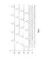
Figure 3 shows optical spectra occurring in an optical filter device according to the invention. -
Figure 4 shows an optical transmitter according to the invention. - The optical transmission system shown in
figure 1 shows a passive optical network in the access area of a telecommunications area. On the left there is shown equipment belonging to a central office of an operator, namely four optical line termination units OLT1, OLT2, OLT3, and OLT4, and a cyclic wavelength division multiplexer Cy-WDM. On the right there is shown equipment belonging to the subscribers' premises, namely six out of a greater number of optical network units ONU1, ..., ONU5, and ONUn. - Of the four optical line termination units OLT1, OLT2, OLT3, and OLT4 here we consider the receive parts. We assume that the number of four such units shows the complete network installation. But from up to two such units measures like those recommended by this invention are demanded; of course with only one such unit such measures are not hindering. In addition, independent from the number of installed such units the number of units in operation may reach from one to the maximum, here four. There is no difference between known such units and those suitable for the invention. They are assumed to have optical inputs that are equally sensitive to all wavelengths within a given operating range.
- The cyclic wavelength division multiplexer Cy-WDM is a key element of this invention and will be described separately with the aid of
figures 2 and3 . - Of the optical network units like ONU1, ..., ONU5, and ONUn here we consider the transmit parts. As already mentioned they may be equipped with conventional DFB lasers and may float with temperature, but in their floating have to skip wavelengths for the other ones. This will be described below with reference to
figure 4 . -
Figure 2 shows an optical filter device Cy-WDM according to the invention. In this example this filter device is adapted to four transmission channels being output at fouroutputs - At the right there is an input I1 connected to an input of an optical wavelength demultiplexer. This demultiplexer filters out each of the allowed wavelengths separately. All of these allowed wavelengths are separated into four sets of wavelengths with each wavelength belonging to one set of wavelengths and the wavelengths of each set of wavelengths being spread over the whole foreseen area of wavelengths.
- In practice the wavelengths are cyclically assigned to the four transmission channels, meaning that all wavelengths belonging to one channel are equally spaced from one another.
- The outputs of this wavelength demultiplexer now are cyclically connected to the inputs of four combining units shown at the left of
figure 2 . Principally these combining units are optical couplers. But depending on the technology used such couplers may have high losses. In practice therefore the use of optical filter devices with a 1XN or here 1X4 matrix may be preferred as such optical combining units. - In practice the whole optical filter device Cy-WDM shown in
figure 2 may be realized in one single component based on the principles of the already mentioned well-known arrayed waveguide gratings AWG. Such component in fact has (in both directions!) an insertion loss lower than that of a splitter. - The latter fact allows the replacement of the element at the branching point of
figure 1 , normally a splitter, with an optical filter device Cy-WDM according to this invention. The freedom of freely changing the assignment between the optical network units like ONU1, ..., ONU5, and ONUn thus would be exchanged against a lower insertion loss. - This is shown in terms of wavelengths in
figure 3 . This example shows 20 wavelengths (or wavelength bands) from lambdal to lambda20 being input to the optical filter device at input I1. They are cyclically allotted to the four transmission channels being output at one each of the fouroutputs - So each of the optical network units ONU1, ..., ONU5, and ONUn depending on the actual traffic situation is assigned to either of these four transmission channels being output on the respective one on
outputs figure 3 such floating is not really free, but such that a lock-in at either of the wavelengths assigned to the respective transmission channels is to be ensured. Such restriction is not really severe, because the shown number of 20 possible channels is only a simplification for better illustration. Actually it is expected to have up to some 50 allowed transmission channels. And even when the restriction in freedom were severe, it would be better than to have no freedom at all. - An example of an optical transmitter according to the invention is shown in
figure 4 . -
Figure 4 shows an optical network unit ONUn including a laser unit LU and a controller uPONU. - The laser unit LU in turn includes a laser diode LD, a temperature sensor TS, and a heater HT.
- Data representing the temperature sensed by the temperature sensor TS is reported to the controller uPONU, whereas the heater is in controlled by the controller uPONU.
- As the operating wavelength of the laser diode LD is directly depending from the laser temperature and such dependency can be deposed within the controller uPONU, it is no problem to set the operating wavelength of the laser diode LD to hit the next allowed transmission channel by slightly increasing or decreasing the heating of the heater HT. Of course decreasing the heating is preferred.
- Instead of or in addition to the heater HT of course a cooling element like a Peltier element could be used.
- Apart from the temperature also the bias current of the laser diode LD is determining the operating wavelength of the laser diode LD. This, of course, can be considered in a similar way by the controller uPONU.
- As
figure 4 only shows the transmit part of an optical network unit like optical network units ONU1, ..., ONU5, and ONUn, it is not shown here, how the allowed transmission channels are reported to the controller uPONU. But this is not a problem in developing such network unit.
Claims (10)
- Method for operating an optical transmission line with several transmission channels (O1, O2, O3, O4) for communication of several optical transmitters (ONU1, ..., ONU5, ONUn) with several optical receivers (OLT1, OLT2, OLT3, OLT4) using different wavelengths (lambda1 to lambda20), where to each optical receiver (OLT1, OLT2, OLT3, OLT4) an optical transmission channel (O1, O2, O3, O4) is assigned, wherein to each transmission channel (O1, O2, O3, 04) a set of different wavelengths (lambda1, lambda5, lambda9 ...; lambda2, lambda6, lambda10 ...; ...) is assigned, wherein each wavelength is assigned to one set of different wavelength only, wherein the wavelengths of each set of wavelengths are spread over an area of wavelength (lambda1 to lambda20) commonly permitted to all sets of wavelengths, wherein to each optical receiver (OLT1, OLT2, OLT3, OLT4) is assigned a set of optical fil ters that pass the wavelengths of one set of wavelengths, and wherein each optical transmitter (ONU1, ..., ONU5, ONUn) chooses a wavelength from the set of wavelengths assigned to it that is usable for it with small effort.
- Method according to claim 1, characterized in, that a transmission channel is assigned to several optical transmitters (ONU1, ..., ONU5, ONUn) to use such transmission mode in a time multiplex manner.
- Optical transmission system (figure 1) with an optical transmission line with several transmission channels (01, 02, 03, 04) for communication of several optical transmitters (ONU1, ..., ONU5, ONUn) with several optical receivers (OLT1, OLT2, OLT3, OLT4) using different wavelengths (lambda1 to lambda20), where to each optical receiver (OLT1, OLT2, OLT3, OLT4) an optical transmission channel (O1, O2, O3, O4) is assigned, wherein to each optical receiver (OLT1, OLT2, OLT3, OLT4) a set of optical filters is assigned, wherein each filter passes one wavelength out of a set of different wavelengths (lambda1, lambda5, lambda9 ...; lambda2, lambda6, lambda10 ...; ...), wherein each set of optical filters includes filters for other wavelengths than the other sets of optical filters, wherein the sets of filters are arranged such that the wavelengths of each set of wavelengths are spread over an area of wavelength (lambda1 to lambda20) commonly permitted to all sets of wavelengths, and wherein each optical transmitter (ONU1, ..., ONU5, ONUn) is built such that it chooses a wavelength from the set of wavelengths assigned to it that is usable for it with small effort.
- Optical transmission system according to claim 3, characterized in, chat the optical transmission line is part of an optical access network.
- Optical transmitter (ONU1, ..., ONU5, ONUn) for an optical transmission system (figure 1) with an optical transmission line with several transmission channels (O1, O2, O3, O4) for communication of several optical transmitters (ONU1, ..., ONU5, ONUn) with several optical receivers (OLT1, OLT2, OLT3, OLT4) using different wavelengths (lambdal to lambda20), where to each optical receiver (OLT1, OLT2, OLT3, OLT4) an optical transmission channel (O1, O2, O3, O4) is assigned, wherein the optical transmitter (ONU1, ..., ONU5, ONUn) is built such that it chooses a wavelength from a set of wavelengths (lambda1, lambda5, lambda9 ...; lambda2, lambda6, lambda10 ...; ...) assigned to it that is usable for it with small effort.
- Set of optical filters for passing one wavelength each out of a set of different wavelengths, that is built such that when combined with at least one further set of optical filters for passing one wavelength each out of a set of different, wavelengths each set of wavelengths (lambda1, lambda5, lambda9 ...; lambda2, lambda6, lambda10 ...; ...) is spread over an area of wavelength (lambda1 to lambda20) commonly permitted to all sets of wavelengths.
- Set of optical filters according to claim 6, characterized in, that the passband wavelengths of the individual filters of this set are spaced equally among one another.
- Optical filter device (Cy-WDM) with at least two sets of optical filters according to claim 6, that complement one another such that they as a whole cover the area of wavelength (lambda1 to lambda20) commonly permitted to all sets of wavelengths, wherein for each set of optical filters an optical combining unit is present, that bundles all wavelengths having passed all filters of this set of optical filters.
- Optical filter device according to claim 8, characterized in, that each optical combining unit is an optical coupler.
- Optical filter device according to claim 8, characterized in, that each optical combining unit is a set of optical filters.
Priority Applications (2)
| Application Number | Priority Date | Filing Date | Title |
|---|---|---|---|
| EP10165739A EP2395690A1 (en) | 2010-06-11 | 2010-06-11 | Method for operating an optical transmission line, optical transmission system, optical transmitter, set of optical filters, and optical filter device |
| PCT/EP2011/056234 WO2011154190A1 (en) | 2010-06-11 | 2011-04-19 | Method for operating an optical transmission line, optical transmission system, optical transmitter, set of optical filters, and optical filter device |
Applications Claiming Priority (1)
| Application Number | Priority Date | Filing Date | Title |
|---|---|---|---|
| EP10165739A EP2395690A1 (en) | 2010-06-11 | 2010-06-11 | Method for operating an optical transmission line, optical transmission system, optical transmitter, set of optical filters, and optical filter device |
Publications (1)
| Publication Number | Publication Date |
|---|---|
| EP2395690A1 true EP2395690A1 (en) | 2011-12-14 |
Family
ID=43259708
Family Applications (1)
| Application Number | Title | Priority Date | Filing Date |
|---|---|---|---|
| EP10165739A Withdrawn EP2395690A1 (en) | 2010-06-11 | 2010-06-11 | Method for operating an optical transmission line, optical transmission system, optical transmitter, set of optical filters, and optical filter device |
Country Status (2)
| Country | Link |
|---|---|
| EP (1) | EP2395690A1 (en) |
| WO (1) | WO2011154190A1 (en) |
Cited By (2)
| Publication number | Priority date | Publication date | Assignee | Title |
|---|---|---|---|---|
| EP2804335A1 (en) | 2013-05-16 | 2014-11-19 | Alcatel Lucent | Optical transmitter suppressing wavelength deviation at the beginning of operation |
| EP3022858A4 (en) * | 2013-07-16 | 2017-03-15 | ADC Telecommunications Inc. | Distributed wave division multiplexing systems |
Citations (4)
| Publication number | Priority date | Publication date | Assignee | Title |
|---|---|---|---|---|
| US20030072052A1 (en) * | 2001-10-10 | 2003-04-17 | Graves Alan F. | Optical wavelength plan for metropolitan photonic network |
| US20030123878A1 (en) * | 2001-12-31 | 2003-07-03 | Li Yuan P. | Wide passband optical interleaver |
| US7231107B1 (en) * | 2003-01-31 | 2007-06-12 | Ciena Corporation | Flexible wavelength selective switch fabric with arbitrary add and drop capability |
| US20090136230A1 (en) * | 2007-11-27 | 2009-05-28 | Fujitsu Limited | System and Method for Managing Wavelength Drift in an Optical Network |
-
2010
- 2010-06-11 EP EP10165739A patent/EP2395690A1/en not_active Withdrawn
-
2011
- 2011-04-19 WO PCT/EP2011/056234 patent/WO2011154190A1/en not_active Ceased
Patent Citations (4)
| Publication number | Priority date | Publication date | Assignee | Title |
|---|---|---|---|---|
| US20030072052A1 (en) * | 2001-10-10 | 2003-04-17 | Graves Alan F. | Optical wavelength plan for metropolitan photonic network |
| US20030123878A1 (en) * | 2001-12-31 | 2003-07-03 | Li Yuan P. | Wide passband optical interleaver |
| US7231107B1 (en) * | 2003-01-31 | 2007-06-12 | Ciena Corporation | Flexible wavelength selective switch fabric with arbitrary add and drop capability |
| US20090136230A1 (en) * | 2007-11-27 | 2009-05-28 | Fujitsu Limited | System and Method for Managing Wavelength Drift in an Optical Network |
Cited By (2)
| Publication number | Priority date | Publication date | Assignee | Title |
|---|---|---|---|---|
| EP2804335A1 (en) | 2013-05-16 | 2014-11-19 | Alcatel Lucent | Optical transmitter suppressing wavelength deviation at the beginning of operation |
| EP3022858A4 (en) * | 2013-07-16 | 2017-03-15 | ADC Telecommunications Inc. | Distributed wave division multiplexing systems |
Also Published As
| Publication number | Publication date |
|---|---|
| WO2011154190A1 (en) | 2011-12-15 |
Similar Documents
| Publication | Publication Date | Title |
|---|---|---|
| Feldman et al. | An evaluation of architectures incorporating wavelength division multiplexing for broad-band fiber access | |
| US7171123B2 (en) | Method for decreasing and compensating the transmission loss at a wavelength-division-multiplexed passive optical network and an apparatus therefor | |
| CN111355554B (en) | Routing multiplexer, routing combining method, wavelength division routing method and network system | |
| US9236971B2 (en) | Bandwidth allocation device and bandwidth allocation method | |
| EP2913947B1 (en) | Passive optical network and optical line terminal | |
| US10097907B2 (en) | Systems and methods of wavelength division multiplex passive optical networking | |
| US20120251108A1 (en) | Optical Communications Networks, Optical Line Terminations and Related Methods | |
| WO2010123285A4 (en) | Wdm pon system with distribution through a periodic arrayed waveguide grating | |
| US6950609B2 (en) | Tunable, multi-port optical add-drop multiplexer | |
| KR101367486B1 (en) | Apparatus and method for operating a wavelength division multiplexing access network | |
| US20130279900A1 (en) | Passive optical network system, method for transmitting and receiving optical signal thereof, and optical line terminal | |
| KR20140110736A (en) | Signal processing method and bidirectional coarse wavelength division multiplexing ring network system for the same | |
| CN105580301B (en) | Halo Network and Its Optical Nodes | |
| EP2395690A1 (en) | Method for operating an optical transmission line, optical transmission system, optical transmitter, set of optical filters, and optical filter device | |
| US11711150B2 (en) | Optical communication system and optical communication method | |
| JP5846007B2 (en) | Subscriber side apparatus registration method and optical network system | |
| EP3091678B1 (en) | Optical wdm transmission network | |
| KR101884393B1 (en) | Method For Allocating Channel in WDM, and System thereof | |
| KR100547834B1 (en) | Wavelength division multiplexed passive optical network with wavelength tracking apparatus and method for wavelength tracking thereof | |
| EP2479906A1 (en) | Method for operating an optical transmission line, optical transmission system, optical transmitter and optical receiver | |
| EP2637333B1 (en) | Optical TDM Backhauling Network | |
| EP2068469B1 (en) | Method for circulating optical signals in a passive optical distribution network | |
| JP4553236B2 (en) | Optical communication method and optical transmission apparatus | |
| JP3971332B2 (en) | Optical wavelength division multiplexing network device, wavelength router, and transmitter / receiver | |
| Moriwaki et al. | Wavelength path reconfigurable AWG-STAR employing coprime-channel-cycle arrayed-waveguide gratings |
Legal Events
| Date | Code | Title | Description |
|---|---|---|---|
| 17P | Request for examination filed |
Effective date: 20110202 |
|
| AK | Designated contracting states |
Kind code of ref document: A1 Designated state(s): AL AT BE BG CH CY CZ DE DK EE ES FI FR GB GR HR HU IE IS IT LI LT LU LV MC MK MT NL NO PL PT RO SE SI SK SM TR |
|
| AX | Request for extension of the european patent |
Extension state: BA ME RS |
|
| PUAI | Public reference made under article 153(3) epc to a published international application that has entered the european phase |
Free format text: ORIGINAL CODE: 0009012 |
|
| 111Z | Information provided on other rights and legal means of execution |
Free format text: AL AT BE BG CH CY CZ DE DK EE ES FI FR GB GR HR HU IE IS IT LI LT LU LV MC MK MT NL NO PL PT RO SE SI SK SM TR Effective date: 20130410 |
|
| RAP1 | Party data changed (applicant data changed or rights of an application transferred) |
Owner name: ALCATEL LUCENT |
|
| D11X | Information provided on other rights and legal means of execution (deleted) | ||
| 17Q | First examination report despatched |
Effective date: 20170324 |
|
| STAA | Information on the status of an ep patent application or granted ep patent |
Free format text: STATUS: THE APPLICATION IS DEEMED TO BE WITHDRAWN |
|
| 18D | Application deemed to be withdrawn |
Effective date: 20170804 |