EP2395648A2 - Systems and methods to optimize outputs of static inverters being supplied by variable energy generation - Google Patents
Systems and methods to optimize outputs of static inverters being supplied by variable energy generation Download PDFInfo
- Publication number
- EP2395648A2 EP2395648A2 EP20110169317 EP11169317A EP2395648A2 EP 2395648 A2 EP2395648 A2 EP 2395648A2 EP 20110169317 EP20110169317 EP 20110169317 EP 11169317 A EP11169317 A EP 11169317A EP 2395648 A2 EP2395648 A2 EP 2395648A2
- Authority
- EP
- European Patent Office
- Prior art keywords
- inverter
- current power
- static
- outputs
- direct current
- Prior art date
- Legal status (The legal status is an assumption and is not a legal conclusion. Google has not performed a legal analysis and makes no representation as to the accuracy of the status listed.)
- Withdrawn
Links
Images


Classifications
-
- H—ELECTRICITY
- H02—GENERATION; CONVERSION OR DISTRIBUTION OF ELECTRIC POWER
- H02M—APPARATUS FOR CONVERSION BETWEEN AC AND AC, BETWEEN AC AND DC, OR BETWEEN DC AND DC, AND FOR USE WITH MAINS OR SIMILAR POWER SUPPLY SYSTEMS; CONVERSION OF DC OR AC INPUT POWER INTO SURGE OUTPUT POWER; CONTROL OR REGULATION THEREOF
- H02M1/00—Details of apparatus for conversion
- H02M1/42—Circuits or arrangements for compensating for or adjusting power factor in converters or inverters
-
- H—ELECTRICITY
- H02—GENERATION; CONVERSION OR DISTRIBUTION OF ELECTRIC POWER
- H02J—ELECTRIC POWER NETWORKS; CIRCUIT ARRANGEMENTS OR SYSTEMS FOR SUPPLYING OR DISTRIBUTING ELECTRIC POWER; SYSTEMS FOR STORING ELECTRIC ENERGY
- H02J3/00—Circuit arrangements for AC mains or AC distribution networks
- H02J3/38—Arrangements for feeding a single network from two or more generators or sources in parallel; Arrangements for feeding already energised networks from additional generators or sources in parallel
- H02J3/381—Dispersed generators
-
- H—ELECTRICITY
- H02—GENERATION; CONVERSION OR DISTRIBUTION OF ELECTRIC POWER
- H02J—ELECTRIC POWER NETWORKS; CIRCUIT ARRANGEMENTS OR SYSTEMS FOR SUPPLYING OR DISTRIBUTING ELECTRIC POWER; SYSTEMS FOR STORING ELECTRIC ENERGY
- H02J3/00—Circuit arrangements for AC mains or AC distribution networks
- H02J3/38—Arrangements for feeding a single network from two or more generators or sources in parallel; Arrangements for feeding already energised networks from additional generators or sources in parallel
- H02J3/46—Controlling the sharing of generated power between the generators, sources or networks
-
- H—ELECTRICITY
- H02—GENERATION; CONVERSION OR DISTRIBUTION OF ELECTRIC POWER
- H02M—APPARATUS FOR CONVERSION BETWEEN AC AND AC, BETWEEN AC AND DC, OR BETWEEN DC AND DC, AND FOR USE WITH MAINS OR SIMILAR POWER SUPPLY SYSTEMS; CONVERSION OF DC OR AC INPUT POWER INTO SURGE OUTPUT POWER; CONTROL OR REGULATION THEREOF
- H02M7/00—Conversion of AC power input into DC power output; Conversion of DC power input into AC power output
- H02M7/42—Conversion of DC power input into AC power output without possibility of reversal
- H02M7/44—Conversion of DC power input into AC power output without possibility of reversal by static converters
- H02M7/48—Conversion of DC power input into AC power output without possibility of reversal by static converters using discharge tubes with control electrode or semiconductor devices with control electrode
-
- H—ELECTRICITY
- H02—GENERATION; CONVERSION OR DISTRIBUTION OF ELECTRIC POWER
- H02J—ELECTRIC POWER NETWORKS; CIRCUIT ARRANGEMENTS OR SYSTEMS FOR SUPPLYING OR DISTRIBUTING ELECTRIC POWER; SYSTEMS FOR STORING ELECTRIC ENERGY
- H02J2101/00—Supply or distribution of decentralised, dispersed or local electric power generation
- H02J2101/20—Dispersed power generation using renewable energy sources
- H02J2101/22—Solar energy
- H02J2101/24—Photovoltaics
-
- H—ELECTRICITY
- H02—GENERATION; CONVERSION OR DISTRIBUTION OF ELECTRIC POWER
- H02J—ELECTRIC POWER NETWORKS; CIRCUIT ARRANGEMENTS OR SYSTEMS FOR SUPPLYING OR DISTRIBUTING ELECTRIC POWER; SYSTEMS FOR STORING ELECTRIC ENERGY
- H02J2101/00—Supply or distribution of decentralised, dispersed or local electric power generation
- H02J2101/20—Dispersed power generation using renewable energy sources
- H02J2101/28—Wind energy
-
- Y—GENERAL TAGGING OF NEW TECHNOLOGICAL DEVELOPMENTS; GENERAL TAGGING OF CROSS-SECTIONAL TECHNOLOGIES SPANNING OVER SEVERAL SECTIONS OF THE IPC; TECHNICAL SUBJECTS COVERED BY FORMER USPC CROSS-REFERENCE ART COLLECTIONS [XRACs] AND DIGESTS
- Y02—TECHNOLOGIES OR APPLICATIONS FOR MITIGATION OR ADAPTATION AGAINST CLIMATE CHANGE
- Y02B—CLIMATE CHANGE MITIGATION TECHNOLOGIES RELATED TO BUILDINGS, e.g. HOUSING, HOUSE APPLIANCES OR RELATED END-USER APPLICATIONS
- Y02B70/00—Technologies for an efficient end-user side electric power management and consumption
- Y02B70/10—Technologies improving the efficiency by using switched-mode power supplies [SMPS], i.e. efficient power electronics conversion e.g. power factor correction or reduction of losses in power supplies or efficient standby modes
-
- Y—GENERAL TAGGING OF NEW TECHNOLOGICAL DEVELOPMENTS; GENERAL TAGGING OF CROSS-SECTIONAL TECHNOLOGIES SPANNING OVER SEVERAL SECTIONS OF THE IPC; TECHNICAL SUBJECTS COVERED BY FORMER USPC CROSS-REFERENCE ART COLLECTIONS [XRACs] AND DIGESTS
- Y02—TECHNOLOGIES OR APPLICATIONS FOR MITIGATION OR ADAPTATION AGAINST CLIMATE CHANGE
- Y02E—REDUCTION OF GREENHOUSE GAS [GHG] EMISSIONS, RELATED TO ENERGY GENERATION, TRANSMISSION OR DISTRIBUTION
- Y02E10/00—Energy generation through renewable energy sources
- Y02E10/50—Photovoltaic [PV] energy
- Y02E10/56—Power conversion systems, e.g. maximum power point trackers
-
- Y—GENERAL TAGGING OF NEW TECHNOLOGICAL DEVELOPMENTS; GENERAL TAGGING OF CROSS-SECTIONAL TECHNOLOGIES SPANNING OVER SEVERAL SECTIONS OF THE IPC; TECHNICAL SUBJECTS COVERED BY FORMER USPC CROSS-REFERENCE ART COLLECTIONS [XRACs] AND DIGESTS
- Y02—TECHNOLOGIES OR APPLICATIONS FOR MITIGATION OR ADAPTATION AGAINST CLIMATE CHANGE
- Y02E—REDUCTION OF GREENHOUSE GAS [GHG] EMISSIONS, RELATED TO ENERGY GENERATION, TRANSMISSION OR DISTRIBUTION
- Y02E10/00—Energy generation through renewable energy sources
- Y02E10/70—Wind energy
- Y02E10/76—Power conversion electric or electronic aspects
Definitions
- At least some embodiments of the disclosure relates to static inverters in general and, more specifically but not limited to, the collection of energy from variable energy generation systems via static inverters.
- variable energy generation systems such as wind, solar, and other opportunistic power generation systems
- the amount of available energy at any given time is not known.
- these systems are often physically distributed over a large area, thus creating a challenge for collecting the energy with minimum power losses.
- a system is configured to collect energy from generation systems such as, for example, wind farms or solar farms with widely distributed energy-generation equipment.
- generation systems such as, for example, wind farms or solar farms with widely distributed energy-generation equipment.
- static inverters are used to feed the energy into a power grid.
- a pulse width modulation is connected in parallel with a static inverter to correct the power factor of the output of the static inverter.
- back-to-back static inverters are used to create a high-voltage DC output for a DC transmission line to collect power from multiple generation sites into one feed-in site for the power grid.
- Figure 1 shows an embodiment of a variable energy generation system with a static inverter
- Figure 2 shows a six-phase star circuit
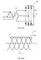
- Figure 3a shows a delta-wye type of transformer
- Figure 3b shows an alternative design of a static inverter or rectifier according to one embodiment
- Figure 4a shows another exemplary simplified static inverter or rectifier in a three-phase full-wave bridge circuit, according to one embodiment
- Figure 4b shows voltage waveforms with output voltage and phase voltages
- Figure 5a shows a balanced inter-reactor system with a delta-wye-wye transformer and a balanced reactor on a separate core;
- Figure 5b shows waveforms that result from a 12-pulse approach
- Figure 6a shows a delta-wye-delta serial configuration of a static inverter
- Figure 6b shows a configuration of a static inverter/rectifier
- Figure 7 shows an embodiment of a variable energy generation system with a combination of a static inverter and a pulse width modulation inverter
- Figure 8 shows an embodiment of a variable energy generation system with multiple static inverters.
- FIG. 1 shows an overview of an exemplary multi-point power generation system 100, according to one embodiment. Shown are string sets 101 a...n, each equipped with a set of energy collecting units (“collectors") 110aa...nn which output direct current (DC). Each string has a string converter 111 a...n that feeds high-voltage into a floating DC bus (e.g., floating relative the ground), typically, for example, in a range between 100 volts and 1000 volts. Some regulatory bodies place limits on the voltages, such as between 50 and 600 volts, in some cases as high as 1000 volts, but for purposes of this discussion, the actual values of these local regulatory limits are not important.
- collectors energy collecting units
- DC direct current
- a static inverter is configured to transform the input voltage into the output voltage at a given ratio.
- an input voltage set at, for example, 500 volts results in a specific AC power at a certain voltage.
- the phase can be adjusted by controlling the timing of the switches used in the static inverter.
- the voltage is not easily adjustable.
- the string converters 111a...n are used to move the floating DC bus up or down according to the current energy production, so that static inverter 120 with its fixed ratio can generate the correct voltage to feed into the grid.
- Static inverters have several properties that can be used for advantage, although in many situations, they also can be problematic.
- One ofthe advantages is that switching losses are substantially lower, as frequencies are much lower, generally (range of 50-400Hz typically).
- the disadvantage is that transformers can be larger. In the case of solar installations the transformer is typically required for system sizes above a power rating of about 20kW (as per today's pending regulations, but a limit will likely be in most cases) as a result of the need to have a galvanic isolation between the grid and the DC bus.
- a transformer is used because solar panels have leakage current at normal operating conditions, as do, in some cases, inverters. The larger the system, the larger and potentially more dangerous are such leakages.
- Standard Pulse Width Modulation (PWM) inverters typically have additional filtering to avoid heating the transformer at the switching frequency, because such inverters are less efficient when driving a transformer directly. These losses are in addition to their switching losses.
- PWM Pulse Width Modulation
- the static inverters can be operated both ways, as converters and as rectifiers (hence inverter), and finally, they have a built-in ratio between input and output voltage that cannot be easily changed.
- this problem is solved via the DC voltage bus that can be adjusted by primary inverters to provide the desired or needed voltage to feed into the grid.
- the static inverters when used to feed into the grid, have a power factor of typically 0.97 or even higher if a system with more than 12 pulses is used. The power factor can be adjusted as described below.
- controller 124 controls switches 123a...n with appropriately insulated drivers (typically driver transformers or optically coupled switches, or both, or other suitable solutions) through control line 126 (drivers not shown).
- Said line 126 is shown here simplified as one line, whereas in reality, line 126 would contain at least a separate control line or pair for each switch, and each line would have a potential separator.
- connection 127 connects to the grid to measure the voltage phase, to ensure that the voltage feed is correct.
- Table 1 shows some aspects of a standard PWM inverter for solar application as compared to the new proposed system using a static inverter solution.
- Table 1 Parameter Standard solution with PWM inverter New proposed system using static inverter Line transformer need Mandatory above 20kw Mandatory above 20kw, but likely always using a transformer DC bus losses At full rated load DC bus voltage is minimal yielding maximum losses at this point DC bus voltage is at its maximum level at full rated load yielding lower conduction losses by 44% (out ofthe typical 1.3% of conduction losses Reliability Components switched at relatively high frequency Low switching frequency. Inverter efficiency higher by more than 1% resulting in lower operation temperature. Aluminum electrolytic not required.
- FIG. 2 shows another approach to using a static inverter, according to one aspect of the system described herein.
- a six-phase star circuit 200 has, instead of diodes 202a...n shown in the figure, switches to generate the alternating current.
- the advantage of such an approach is that only one switch is in series, hence reducing conduction losses.
- the transformer 201 is more complicated, with additional windings 201d...i on one side (double wye), and a regular delta with three windings 201 a...c on the other side (AC).
- Figure 3a shows a typical delta (304b)-wye (304a) type of transformer (ac winding not shown here) in static inverter or rectifier 301.
- diodes 305a...fand 306a...f are shown for operation in a rectifying mode, feeding through a balance transformer 303 into a load 302.
- switches such as, for example, FETs, SCRs, IGBTs etc, this topology could be used to both rectify or up-convert.
- FIG. 3b shows an alternative design of static inverter or rectifier 310, according to another aspect of the system disclosed herein.
- Static inverter or rectifier 310 does not have balancing transformer 303. Shown are delta windings 311a and wye windings 311b. Also shown are the two sets of switches (as discussed above) or diodes 313a...fand 314a...f.
- the DC bus or load is resistor RL 312.
- Figure 4a shows another exemplary simplified static inverter or rectifier in three-phase full-wave bridge circuit 400, according to one aspect ofthe system disclosed herein.
- Circuit 400 is a 5-pulse type static inverter, characterized by a simpler transformer 401 (only three windings as a delta or wye on the switches side), as opposed to the 12-pulse static inverter or rectifier discussed in other sections that requires a total of six windings (typically as one set of three in a delta and another three in a wye).
- circuit 400 has a stronger ripple 411 (than a 12-pulse static inverter or rectifier would have), which can be seen in Figure 4b .
- Diodes 402a...f are used for rectifiers, or switches would be used for static inverters. Controlled rectifiers or other suitable switches such as MOSFeT, IGBT, or even mercury valves may be used according to the voltage being handled. Also shown is the DC bus or DC load 403.
- Figure 4b shows voltage waveforms 410, with output voltage 412 and phase voltages 413a...c.
- Figure 5a shows a balanced inter-reactor system 500 with a delta-wye-wye transformer and a balanced reactor on a separate core.
- Transformer 501 has an AC side delta winding 501a and two primary windings 501b and 501c. Windings 501b and 501c have different winding ratios and/or phase assignments, thus supporting creation of a 12-pulse conversion static inverter or rectifier.
- SCRs instead of standard rectifiers 504a...c and 505a...c, SCRs or other, suitable switching devices may be used.
- Figure 5b shows the waveforms 510 that result from a 12-pulse approach, instead of a 6-pulse approach. Voltages are overlaid such that a very small ripple results with less than 3 percent load factor. In many cases, using the 12 pulse approach is sufficient filtering for connection to a grid; however in other cases, additional correction may be required, as discussed below in the description of Figure 7 . Thus when operating from AC to DC, only minimal filter capacity needs to be added, or when operating the other way, minimal power factor correction needs to be done.
- Figure 6a shows a delta-wye-delta serial configuration of a static inverter 600 that does not require a balancing transformer. Also, as the two sets of switches are in series, the operating DC voltage can be roughly twice in relation to the breakdown voltage of the switches, as in a parallel configuration. Two sets of diodes or SCRs 603a...f and 604a...f are in series. As a result, the voltage is split (not evenly, but typically 1:2), resulting in the desired 12-step AC voltage that is commonly known in static inverters.
- Figure 6b shows a different view of a configuration of a static inverter/rectifier 620. Shown is the DC bus 626, the two DC side windings 621 and 624, as well as AC side windings 625 (all on same core), switches 622a...l and balancing transformer 623.
- FIG. 7 shows an exemplary high-level overview of a complete variable DC power generation and AC conversion system 700, according to one aspect of the system disclosed herein.
- Controller 704 interacts with multiple energy-producing units 701 a...n such as, for example, a multi-unit solar pole, or a windmill, to maintain the desired voltage on the bus.
- energy-producing units 701 a...n such as, for example, a multi-unit solar pole, or a windmill
- an optional rotary capacitor 707 which in this case may be some kind of a motor with a fly wheel.
- the field current may be used to control addition or reduction of energy and thus to stabilize the bus more efficiently and/or cost effectively in some cases than an actual capacitor, depending on the size ofthe system. In smaller systems, typically, standard capacitors are used.
- Static inverter 702 inverts DC energy to three-phase power and connects to feeding point 705, and thence to the grid.
- An additional pulse width modulation inverter (PWMI) 703 corrects the power factor error generated by the static inverter using the 12-pulse generation method. Also, the additional power with modulation in highfrequency inverter 703 runs on higher frequency as it runs on lower power. In some cases, an additional rotary capacitor or other compensation capacitor may be required at grid connection point 705 before the energy is fed into the grid.
- the static inverter 702 is connected in parallel with the pulse width modulation inverter 703.
- the static inverter 702 and the pulse width modulation inverter 703 both receive DC input from the bus to which the rotary capacitor 707 is connected.
- the static inverter 702 and the pulse width modulation inverter 703 both output alternating current power to the feeding point 705.
- the pulse width modulation inverter is configured to correct the power factor error in the output of the static inverter 702 and/or to reduce the ripple 411 in the output of the static inverter 702.
- the controller 704 is configured to coordinate the two inverters so that the output power has a proper waveform.
- the converter 704, or a separate controller, is connected in one embodiment to the feeding point 705 to insure that the combined output power from the static inverter 702 and the pulse width modulation inverter 703 is compatible with the grid 706.
- the controller 704 is configured to monitor the power factor and/or the ripple 411 in the output to the feeding point 705.
- the controller 704 controls the operations of the pulse width modulation inverter 703 and/or the static inverter 702 to reduce the error in the power factor and/or the ripple 411 that are in the power provided to the feeding power 705.
- the controller 704 is configured to detect the ripple 411 in the output of the static inverter 702 and adjust the operation of the pulse width modulation inverter 703 to reduce the ripple when the output of the pulse width modulation inverter 703 is combined with the output of the static inverter 702.
- the controller 704 is configured to synchronize the operations of the static inverter 702 and the pulse width modulation inverter 703 according to predetermined parameters, such as frequency, phase offset, etc., to reduce increase the power factor and/or reduce the ripple in the combined output provided to the feeding point.
- the controller 704 is configured to adjust the synchronization ofthe operations of the static inverter 702 and the pulse width modulation inverter 703, e.g., by adjusting frequency, phase offset, etc., to search for an optimized operation point that increases the power factor and/or reduce the ripple in the combined output provided to the feeding point 705.
- the controller 704 is in one embodiment configured to operate the statistic inverter at a first state, adjust the operating parameter of the pulse width modulation inverter 703 while monitoring the change in the power factor in the combined output provided to the feeding point 705. The adjustment is made in a direction to improve the power factor.
- the pulse width modulation inverter 703 is configured to convert a portion of the power provided to the feeding point 705 in a magnitude that correspond to the ripple 411 in the output of the static inverter 702.
- the output of the pulse width modulation inverter 703 is sufficient to correct the power factor, while the majority of the power provided to the feeding point 705 is converted by the static inverter to take advantage of the general benefit of the static inverter over the pulse width modulation inverter (e.g., better efficiency, higher operation power, etc.).
- variable collecting unit(s) may be solar panels, solar poles, wind power collectors, or other variable or intermittent power collecting unit(s) such as tidal power generators.
- String convertor(s) collect power from respective unit(s) and output direct current power to a bus that provides the power in direct current to the inverters 702 and 703.
- the controller 704 further connects to the string converter(s) 111a...n to coordinate a conversion of the power for compatibility on the bus.
- a rotary capacitor 707, or other type of capacitor is connected to the bus.
- a static inverter as discussed in connection with Figures 1 to 6b is used as the statistic inverter 702 in Figure 7 .
- FIG. 8 shows a system 800 similar to system 700, wherein each energy production unit, such as, for example, a solar power pole, wind generator, etc. generates a variable, controlled voltage.
- each energy production unit such as, for example, a solar power pole, wind generator, etc. generates a variable, controlled voltage.
- two back-to-back static inverters 801al and 801 a2 convert the variable DC voltage first into an alternating current, then back into a high-voltage direct current (HVDC), used for a high-voltage transmission line 810.
- HVDC high-voltage direct current
- an additional static inverter 802 inverts the power into three-phase AC, which is then is then fed into the grid at point 803.
- Controller 804 interfaces between the grid measurement, the master static inverter 802, and the power generation units at the far end, to balance the voltage on the local DC buses 801a5 that are fed into the internal primary and secondary static inverters 801a1 and 801 a2.
- Additional energy production units 801 a...n could be, for example, a multi-unit solar pole, or a windmill, or any other variable-power generation unit.
- a pulse width modulation inverter 703 in parallel with the statistic inverter 701 to correct power factor and/or reduce ripple in a way as illustrated in Figure 7 .
- a pulse width modulation inverter 703 in parallel with the statistic inverter 801 to correct power factor and/or reduce ripple in a way as illustrated in Figure 7 .
- One embodiment involves collecting energy from variable energy sources such as solar or wind energy, by strings of collectors (for example photovoltaic cells or panels, or wind turbines) as managed by string convertors and controller(s). Then compatible electrical energy is transported on a bus to a static inverter including a transformer (such as a delta-wye-delta transformer) and a balance transformer.
- the static inverter outputs alternating current at a given voltage.
- the controller(s) monitor voltage phase on a grid and manages the static inverter so that the alternating current is compatible with grid current.
- the topology of the system includes both a static inverter and a pulse width modulation inverter. Current flows through the static inverter and the pulse width inverter to a feeding point and then onto a grid.
- Yet another embodiment again involves collecting energy from variable energy sources.
- Current flows into a static inverter to convert direct current into alternating current. From that point, the alternating current flows into a second static inverter to convert the alternating current into high voltage direct current which is transported on a high voltage direct current transmission line to a master static inverter which in turn converts the direct current into alternating current suitable for transmission via a grid.
Landscapes
- Engineering & Computer Science (AREA)
- Power Engineering (AREA)
- Inverter Devices (AREA)
- Wind Motors (AREA)
Abstract
Description
- At least some embodiments of the disclosure relates to static inverters in general and, more specifically but not limited to, the collection of energy from variable energy generation systems via static inverters.
- In variable energy generation systems, such as wind, solar, and other opportunistic power generation systems, the amount of available energy at any given time is not known. Also, these systems are often physically distributed over a large area, thus creating a challenge for collecting the energy with minimum power losses.
- Some embodiments ofthe disclosure are summarized in this section.
- In one embodiment, a system is configured to collect energy from generation systems such as, for example, wind farms or solar farms with widely distributed energy-generation equipment. In one embodiment, static inverters are used to feed the energy into a power grid.
- In one embodiment, a pulse width modulation is connected in parallel with a static inverter to correct the power factor of the output of the static inverter.
- In one embodiment, back-to-back static inverters are used to create a high-voltage DC output for a DC transmission line to collect power from multiple generation sites into one feed-in site for the power grid.
- These and other objects will become clear to those skilled in the art in view of the description of the best presently known mode of implementing the embodiments and the industrial applicability of the preferred embodiment as described herein and as illustrated in the figures of the drawings. The embodiments are illustrated by way of example and not limitation.
- The embodiments will be apparent from the following detailed description in conjunction with the appended figures of drawings, in which:
-
Figure 1 shows an embodiment of a variable energy generation system with a static inverter; -
Figure 2 shows a six-phase star circuit; -
Figure 3a shows a delta-wye type of transformer; -
Figure 3b shows an alternative design of a static inverter or rectifier according to one embodiment; -
Figure 4a shows another exemplary simplified static inverter or rectifier in a three-phase full-wave bridge circuit, according to one embodiment; -
Figure 4b shows voltage waveforms with output voltage and phase voltages; -
Figure 5a shows a balanced inter-reactor system with a delta-wye-wye transformer and a balanced reactor on a separate core; -
Figure 5b shows waveforms that result from a 12-pulse approach; -
Figure 6a shows a delta-wye-delta serial configuration of a static inverter; -
Figure 6b shows a configuration of a static inverter/rectifier; -
Figure 7 shows an embodiment of a variable energy generation system with a combination of a static inverter and a pulse width modulation inverter; and -
Figure 8 shows an embodiment of a variable energy generation system with multiple static inverters. - In the various figures of the drawings, like references are used to denote like or similar elements.
- The following description and drawings are illustrative and are not to be construed as limiting. Numerous specific details are described to provide a thorough understanding. However, in certain instances, well known or conventional details are not described in order to avoid obscuring the description. References to one or an embodiment in the present disclosure are not necessarily references to the same embodiment; and, such references mean at least one.
- The use of headings herein is merely provided for ease of reference, and shall not be interpreted in any way to limit this disclosure or the following claims.
- Reference in this specification to "one embodiment" or "an embodiment" means that a particular feature, structure, or characteristic described in connection with the embodiment is included in at least one embodiment of the disclosure. The appearances of the phrase "in one embodiment" in various places in the specification are not necessarily all referring to the same embodiment, nor are separate or alternative embodiments mutually exclusive of other embodiments. Moreover, various features are described which may be exhibited by some embodiments and not by others. Similarly, various requirements are described which may be requirements for some embodiments but not other embodiments. As a result, this specification represents a disclosure of all possible combinations of features described herein, except that certain combinations are excluded by reasons of mutually exclusive relationships in features, where the mutual exclusiveness is either explicitly identified in this specification or is apparent from the description ofthe respective features.
-
Figure 1 shows an overview of an exemplary multi-pointpower generation system 100, according to one embodiment. Shown arestring sets 101 a...n, each equipped with a set of energy collecting units ("collectors") 110aa...nn which output direct current (DC). Each string has astring converter 111 a...n that feeds high-voltage into a floating DC bus (e.g., floating relative the ground), typically, for example, in a range between 100 volts and 1000 volts. Some regulatory bodies place limits on the voltages, such as between 50 and 600 volts, in some cases as high as 1000 volts, but for purposes of this discussion, the actual values of these local regulatory limits are not important. - A static inverter is configured to transform the input voltage into the output voltage at a given ratio. Thus, an input voltage set at, for example, 500 volts, results in a specific AC power at a certain voltage. To feed properly into the grid, the voltage and the phase is adjusted. The phase can be adjusted by controlling the timing of the switches used in the static inverter. However, in normal operation, the voltage is not easily adjustable.
- In the
exemplary system 100 ofFigure 1 , thestring converters 111a...n are used to move the floating DC bus up or down according to the current energy production, so thatstatic inverter 120 with its fixed ratio can generate the correct voltage to feed into the grid. - Static inverters have several properties that can be used for advantage, although in many situations, they also can be problematic. One ofthe advantages is that switching losses are substantially lower, as frequencies are much lower, generally (range of 50-400Hz typically). The disadvantage is that transformers can be larger. In the case of solar installations the transformer is typically required for system sizes above a power rating of about 20kW (as per today's pending regulations, but a limit will likely be in most cases) as a result of the need to have a galvanic isolation between the grid and the DC bus. A transformer is used because solar panels have leakage current at normal operating conditions, as do, in some cases, inverters. The larger the system, the larger and potentially more dangerous are such leakages.
- Standard Pulse Width Modulation (PWM) inverters typically have additional filtering to avoid heating the transformer at the switching frequency, because such inverters are less efficient when driving a transformer directly. These losses are in addition to their switching losses.
- The static inverters can be operated both ways, as converters and as rectifiers (hence inverter), and finally, they have a built-in ratio between input and output voltage that cannot be easily changed. In one embodiment, in the examples discussed herein, this problem is solved via the DC voltage bus that can be adjusted by primary inverters to provide the desired or needed voltage to feed into the grid. Lastly, when used to feed into the grid, the static inverters according to one embodiment have a power factor of typically 0.97 or even higher if a system with more than 12 pulses is used. The power factor can be adjusted as described below.
- In one embodiment, the aforementioned generation of the correct voltage is done with the help of
controller 124, which hasconnections 125 to the string converters, setting the voltage outputs they need to generate. Further,controller 124 controls switches 123a...n with appropriately insulated drivers (typically driver transformers or optically coupled switches, or both, or other suitable solutions) through control line 126 (drivers not shown). Saidline 126 is shown here simplified as one line, whereas in reality,line 126 would contain at least a separate control line or pair for each switch, and each line would have a potential separator. Additionally,connection 127 connects to the grid to measure the voltage phase, to ensure that the voltage feed is correct. Also shown isdata connection 128, which connection could connect via the Internet or some other public or private network to the electric utility, sending real-time data about energy being delivered, as well as to a supervisory site that could control multiple power generation sites. - Table 1, below, shows some aspects of a standard PWM inverter for solar application as compared to the new proposed system using a static inverter solution.
Table 1 Parameter Standard solution with PWM inverter New proposed system using static inverter Line transformer need Mandatory above 20kw Mandatory above 20kw, but likely always using a transformer DC bus losses At full rated load DC bus voltage is minimal yielding maximum losses at this point DC bus voltage is at its maximum level at full rated load yielding lower conduction losses by 44% (out ofthe typical 1.3% of conduction losses Reliability Components switched at relatively high frequency Low switching frequency. Inverter efficiency higher by more than 1% resulting in lower operation temperature. Aluminum electrolytic not required. EMI Mainly affected by switching frequency Low frequency component only Local MPPT for maximum energy harvesting None Full solution solving all mismatch conditions as result of thermal, aging, soiling initial tolerances, shade. Price for local MPPT Need separate AC inverter per each power segment Local MPPT by simple stage and simple DC-AC inverter lowest price possible Cooling Need separate fans Transformer and switches can operate with natural convection cooling. -
Figure 2 shows another approach to using a static inverter, according to one aspect of the system described herein. In this approach, a six-phase star circuit 200 has, instead ofdiodes 202a...n shown in the figure, switches to generate the alternating current. The advantage of such an approach is that only one switch is in series, hence reducing conduction losses. However thetransformer 201 is more complicated, withadditional windings 201d...i on one side (double wye), and a regular delta with threewindings 201 a...c on the other side (AC). -
Figure 3a shows a typical delta (304b)-wye (304a) type of transformer (ac winding not shown here) in static inverter or rectifier 301. In this example,diodes 305a...fand 306a...f are shown for operation in a rectifying mode, feeding through abalance transformer 303 into aload 302. In other cases, if the load is replaced with a DC bus and the diodes are replaced with switches such as, for example, FETs, SCRs, IGBTs etc, this topology could be used to both rectify or up-convert. -
Figure 3b shows an alternative design of static inverter orrectifier 310, according to another aspect of the system disclosed herein. Static inverter orrectifier 310 does not have balancingtransformer 303. Shown aredelta windings 311a andwye windings 311b. Also shown are the two sets of switches (as discussed above) ordiodes 313a...fand 314a...f. The DC bus or load isresistor RL 312. -
Figure 4a shows another exemplary simplified static inverter or rectifier in three-phase full-wave bridge circuit 400, according to one aspect ofthe system disclosed herein.Circuit 400 is a 5-pulse type static inverter, characterized by a simpler transformer 401 (only three windings as a delta or wye on the switches side), as opposed to the 12-pulse static inverter or rectifier discussed in other sections that requires a total of six windings (typically as one set of three in a delta and another three in a wye). As a result,circuit 400 has a stronger ripple 411 (than a 12-pulse static inverter or rectifier would have), which can be seen inFigure 4b .Diodes 402a...f are used for rectifiers, or switches would be used for static inverters. Controlled rectifiers or other suitable switches such as MOSFeT, IGBT, or even mercury valves may be used according to the voltage being handled. Also shown is the DC bus orDC load 403. -
Figure 4b showsvoltage waveforms 410, withoutput voltage 412 andphase voltages 413a...c. -
Figure 5a shows a balancedinter-reactor system 500 with a delta-wye-wye transformer and a balanced reactor on a separate core.Transformer 501 has an AC side delta winding 501a and twoprimary windings Windings standard rectifiers 504a...c and 505a...c, SCRs or other, suitable switching devices may be used. -
Figure 5b shows thewaveforms 510 that result from a 12-pulse approach, instead of a 6-pulse approach. Voltages are overlaid such that a very small ripple results with less than 3 percent load factor. In many cases, using the 12 pulse approach is sufficient filtering for connection to a grid; however in other cases, additional correction may be required, as discussed below in the description ofFigure 7 . Thus when operating from AC to DC, only minimal filter capacity needs to be added, or when operating the other way, minimal power factor correction needs to be done. -
Figure 6a shows a delta-wye-delta serial configuration of astatic inverter 600 that does not require a balancing transformer. Also, as the two sets of switches are in series, the operating DC voltage can be roughly twice in relation to the breakdown voltage of the switches, as in a parallel configuration. Two sets of diodes orSCRs 603a...f and 604a...f are in series. As a result, the voltage is split (not evenly, but typically 1:2), resulting in the desired 12-step AC voltage that is commonly known in static inverters. Clearly visible are the AC sides of the transformer 602 with, all on the same core, delta winding 602a, the main winding 602b, also a delta winding, and minor winding 602c, which is a wye winding. Placing the two sets ofinverter switches 603a...fand 604a...f in series obviates the necessity for a balancing transformer. Alternating current is delivered atconnection point 601. -
Figure 6b shows a different view of a configuration of a static inverter/rectifier 620. Shown is theDC bus 626, the twoDC side windings transformer 623. -
Figure 7 shows an exemplary high-level overview of a complete variable DC power generation andAC conversion system 700, according to one aspect of the system disclosed herein.Controller 704 interacts with multiple energy-producingunits 701 a...n such as, for example, a multi-unit solar pole, or a windmill, to maintain the desired voltage on the bus. Also shown is an optionalrotary capacitor 707, which in this case may be some kind of a motor with a fly wheel. In such a rotary capacitor, the field current may be used to control addition or reduction of energy and thus to stabilize the bus more efficiently and/or cost effectively in some cases than an actual capacitor, depending on the size ofthe system. In smaller systems, typically, standard capacitors are used.Static inverter 702 inverts DC energy to three-phase power and connects tofeeding point 705, and thence to the grid. An additional pulse width modulation inverter (PWMI) 703 corrects the power factor error generated by the static inverter using the 12-pulse generation method. Also, the additional power with modulation inhighfrequency inverter 703 runs on higher frequency as it runs on lower power. In some cases, an additional rotary capacitor or other compensation capacitor may be required atgrid connection point 705 before the energy is fed into the grid. - In
Figure 7 , thestatic inverter 702 is connected in parallel with the pulsewidth modulation inverter 703. Thestatic inverter 702 and the pulsewidth modulation inverter 703 both receive DC input from the bus to which therotary capacitor 707 is connected. Thestatic inverter 702 and the pulsewidth modulation inverter 703 both output alternating current power to thefeeding point 705. The pulse width modulation inverter is configured to correct the power factor error in the output of thestatic inverter 702 and/or to reduce theripple 411 in the output of thestatic inverter 702. - In one embodiment, the
controller 704 is configured to coordinate the two inverters so that the output power has a proper waveform. Theconverter 704, or a separate controller, is connected in one embodiment to thefeeding point 705 to insure that the combined output power from thestatic inverter 702 and the pulsewidth modulation inverter 703 is compatible with thegrid 706. - In one embodiment, the
controller 704 is configured to monitor the power factor and/or theripple 411 in the output to thefeeding point 705. Thecontroller 704 controls the operations of the pulsewidth modulation inverter 703 and/or thestatic inverter 702 to reduce the error in the power factor and/or theripple 411 that are in the power provided to thefeeding power 705. - In one embodiment, the
controller 704 is configured to detect theripple 411 in the output of thestatic inverter 702 and adjust the operation of the pulsewidth modulation inverter 703 to reduce the ripple when the output of the pulsewidth modulation inverter 703 is combined with the output of thestatic inverter 702. - In one embodiment, the
controller 704 is configured to synchronize the operations of thestatic inverter 702 and the pulsewidth modulation inverter 703 according to predetermined parameters, such as frequency, phase offset, etc., to reduce increase the power factor and/or reduce the ripple in the combined output provided to the feeding point. - In one embodiment, the
controller 704 is configured to adjust the synchronization ofthe operations of thestatic inverter 702 and the pulsewidth modulation inverter 703, e.g., by adjusting frequency, phase offset, etc., to search for an optimized operation point that increases the power factor and/or reduce the ripple in the combined output provided to thefeeding point 705. For example, thecontroller 704 is in one embodiment configured to operate the statistic inverter at a first state, adjust the operating parameter of the pulsewidth modulation inverter 703 while monitoring the change in the power factor in the combined output provided to thefeeding point 705. The adjustment is made in a direction to improve the power factor. - In one embodiment, the pulse
width modulation inverter 703 is configured to convert a portion of the power provided to thefeeding point 705 in a magnitude that correspond to theripple 411 in the output of thestatic inverter 702. Thus, the output of the pulsewidth modulation inverter 703 is sufficient to correct the power factor, while the majority of the power provided to thefeeding point 705 is converted by the static inverter to take advantage of the general benefit of the static inverter over the pulse width modulation inverter (e.g., better efficiency, higher operation power, etc.). - Further details and examples of correcting a power factor error and creating a proper waveform are discussed in
U.S. Patent Application Publication No. 2010/0332047, published on Dec. 30, 2010 and entitled "Systems and Methods for Distributed Power Factor Correction and Phase Balancing," the disclosure of which is incorporated herein by reference. - In
Figure 7 , the input power for thestatic inverter 702 and the pulsewidth modulation inverter 703 originates with variable collecting unit(s) that may be solar panels, solar poles, wind power collectors, or other variable or intermittent power collecting unit(s) such as tidal power generators. String convertor(s) collect power from respective unit(s) and output direct current power to a bus that provides the power in direct current to theinverters controller 704 further connects to the string converter(s) 111a...n to coordinate a conversion of the power for compatibility on the bus. In one embodiment, arotary capacitor 707, or other type of capacitor, is connected to the bus. - In one embodiment, a static inverter as discussed in connection with
Figures 1 to 6b is used as thestatistic inverter 702 inFigure 7 . -
Figure 8 shows asystem 800 similar tosystem 700, wherein each energy production unit, such as, for example, a solar power pole, wind generator, etc. generates a variable, controlled voltage. In exemplaryenergy production unit 801a, two back-to-back static inverters 801al and 801 a2 convert the variable DC voltage first into an alternating current, then back into a high-voltage direct current (HVDC), used for a high-voltage transmission line 810. At the end oftransmission line 810 an additionalstatic inverter 802 inverts the power into three-phase AC, which is then is then fed into the grid atpoint 803.Controller 804 interfaces between the grid measurement, the masterstatic inverter 802, and the power generation units at the far end, to balance the voltage on the local DC buses 801a5 that are fed into the internal primary and secondary static inverters 801a1 and 801 a2. Additionalenergy production units 801 a...n could be, for example, a multi-unit solar pole, or a windmill, or any other variable-power generation unit. - In one embodiment, a pulse
width modulation inverter 703 in parallel with the statistic inverter 701 to correct power factor and/or reduce ripple in a way as illustrated inFigure 7 . - In one embodiment, a pulse
width modulation inverter 703 in parallel with the statistic inverter 801 to correct power factor and/or reduce ripple in a way as illustrated inFigure 7 . - The claims included herein include several embodiments. One embodiment involves collecting energy from variable energy sources such as solar or wind energy, by strings of collectors (for example photovoltaic cells or panels, or wind turbines) as managed by string convertors and controller(s). Then compatible electrical energy is transported on a bus to a static inverter including a transformer (such as a delta-wye-delta transformer) and a balance transformer. The static inverter outputs alternating current at a given voltage. The controller(s) monitor voltage phase on a grid and manages the static inverter so that the alternating current is compatible with grid current.
- Another embodiment also involves collecting energy from variable energy sources. In this instance, the topology of the system includes both a static inverter and a pulse width modulation inverter. Current flows through the static inverter and the pulse width inverter to a feeding point and then onto a grid.
- Yet another embodiment again involves collecting energy from variable energy sources. Current flows into a static inverter to convert direct current into alternating current. From that point, the alternating current flows into a second static inverter to convert the alternating current into high voltage direct current which is transported on a high voltage direct current transmission line to a master static inverter which in turn converts the direct current into alternating current suitable for transmission via a grid.
- While the particular system and apparatus for the use of static inverters in variable energy generation environments as herein shown and described in detail, is fully capable of attaining the above-described objects, it is to be understood that it is the presently preferred embodiment, and is thus representative of the subject matter which is broadly contemplated, that the scope ofthe disclosure fully encompasses other embodiments which can become obvious to those skilled in the art, and that the scope of the disclosure is accordingly to be limited by nothing other than the appended claims, in which reference to an element in the singular means "at least one." All structural and functional equivalents to the elements ofthe above-described preferred embodiment that are known or later come to be known to those of ordinary skill in the art are expressly incorporated herein by reference and are intended to be encompassed by the present claims. Moreover, it is not necessary for a device to address each and every problem sought to be solved in the disclosure, for it to be encompassed by the present claims. Furthermore, no element or component in the present disclosure is intended to be dedicated to the public, regardless of whether the element or component is explicitly recited in the claims.
- The specific embodiments described herein are not intended to be limiting and features of any embodiments may be combined with features of all other embodiments without departing from the scope ofthe disclosure.
Claims (15)
- An energy generation system comprising:a static inverter to provide an alternating current power to a feeding point; anda pulse width modulation inverter connected in parallel with the static inverter to correct a power factor error in the alternating current power provided by the static inverter.
- The system of claim 1, further comprising a controller in communication with the static inverter and the pulse width modulation inverter wherein the controller coordinates the static inverter and the pulse width modulation inverter to correct a waveform of the alternating current power.
- The system of claim 1 or claim 2, further comprising a controller in communication with the feeding point to coordinate the alternating current power with a grid.
- The system of any preceding claim, wherein the static inverter inverts a direct current power to a three-phase form of the alternating current power.
- The system of any preceding claim, further comprising a bus to supply a direct current power to the static inverter and the pulse width modulation inverter.
- The system of claim 5, further comprising:a plurality of variable energy collecting units to produce respective direct current power outputs; anda plurality of string converters to receive the respective outputs;wherein the string converters supply the respective outputs to the bus in the form of the direct current power.
- The system of claim 6, wherein the units are selected from the group consisting of one or more of solar panels, solar poles, and wind power collectors, or any combination thereof.
- The system of claim 5, further comprising:one or more variable energy collecting units to produce respective direct current power outputs;one or more respective string converters to receive the respective outputs; anda controller in communication with the string converters to enable a conversion of the respective outputs to compatible outputs;wherein the string converters supply the compatible outputs to the bus in the form ofthe direct current power.
- The system of claim 8, further comprising a rotary capacitor in electrical communication with the bus, wherein the units are selected from the group consisting of solar panels, solar poles, wind power collectors, and any combination thereof.
- A method for converting energy comprising:providing, via a static inverter, an alternating current power to a feeding point; andcorrecting, via a pulse width modulation inverter connected in parallel with the static inverter, a power factor error in the alternating current power provided by the static inverter.
- The method of claim 10, further comprising coordinating, via a controller in communication with the static inverter and pulse width modulation inverter, the static inverter and the pulse width modulation inverter, to correct a waveform of the alternating current power.
- The method of claim 10 or claim 11, further comprising coordinating the alternating current power with a grid via a controller in communication with the feeding point.
- The method of any of claims 10, 11 or 12, wherein the static inverter inverts a direct current power to a three-phase form of the alternating current power.
- The method of any of claims 10, 11 or 12, further comprising:supplying a direct current power to the static inverter and the pulse width modulation inverter via a bus;producing via one or more variable energy collecting units respective direct current power outputs; andreceiving via one or more respective string converters the respective outputs;wherein the string converters supply the respective outputs to the bus in the form of the direct current power.
- The method of claim 10, further comprising:supplying a direct current power to the static inverter and the pulse width modulation inverter via a bus;producing via one or more variable energy collecting units respective direct current power outputs;receiving via one or more respective string converters the respective outputs; andinstructing, via a controller in communication with the string converters, the one or more respective string converters to convert the respective outputs to compatible outputs on the bus.
Applications Claiming Priority (1)
| Application Number | Priority Date | Filing Date | Title |
|---|---|---|---|
| US39732010P | 2010-06-09 | 2010-06-09 |
Publications (2)
| Publication Number | Publication Date |
|---|---|
| EP2395648A2 true EP2395648A2 (en) | 2011-12-14 |
| EP2395648A3 EP2395648A3 (en) | 2016-12-14 |
Family
ID=44503523
Family Applications (1)
| Application Number | Title | Priority Date | Filing Date |
|---|---|---|---|
| EP11169317.2A Withdrawn EP2395648A3 (en) | 2010-06-09 | 2011-06-09 | Systems and methods to optimize outputs of static inverters being supplied by variable energy generation |
Country Status (2)
| Country | Link |
|---|---|
| US (6) | US9225261B2 (en) |
| EP (1) | EP2395648A3 (en) |
Cited By (41)
| Publication number | Priority date | Publication date | Assignee | Title |
|---|---|---|---|---|
| WO2014121826A1 (en) * | 2013-02-06 | 2014-08-14 | Abb Technology Ltd | Solar power plant, method of controlling a solar power plant and a dc/dc conversion system |
| EP2854280A1 (en) * | 2013-09-13 | 2015-04-01 | GE Energy Power Conversion Technology Ltd | High voltage DC power conversion system and method of operating the same |
| CN106099907A (en) * | 2016-05-21 | 2016-11-09 | 国电南瑞科技股份有限公司 | Meter and transient state and the online emergent control decision method of static security scleronomic constraint |
| US10097007B2 (en) | 2006-12-06 | 2018-10-09 | Solaredge Technologies Ltd. | Method for distributed power harvesting using DC power sources |
| EP3389159A1 (en) * | 2012-01-30 | 2018-10-17 | Solaredge Technologies Ltd. | Maximizing power in a photovoltaic distributed power system |
| US10116217B2 (en) | 2007-08-06 | 2018-10-30 | Solaredge Technologies Ltd. | Digital average input current control in power converter |
| US10184965B2 (en) | 2006-12-06 | 2019-01-22 | Solaredge Technologies Ltd. | Monitoring of distributed power harvesting systems using DC power sources |
| US10230245B2 (en) | 2006-12-06 | 2019-03-12 | Solaredge Technologies Ltd | Battery power delivery module |
| US10230310B2 (en) | 2016-04-05 | 2019-03-12 | Solaredge Technologies Ltd | Safety switch for photovoltaic systems |
| US10381977B2 (en) | 2012-01-30 | 2019-08-13 | Solaredge Technologies Ltd | Photovoltaic panel circuitry |
| US10396662B2 (en) | 2011-09-12 | 2019-08-27 | Solaredge Technologies Ltd | Direct current link circuit |
| US10447150B2 (en) | 2006-12-06 | 2019-10-15 | Solaredge Technologies Ltd. | Distributed power harvesting systems using DC power sources |
| US10461687B2 (en) | 2008-12-04 | 2019-10-29 | Solaredge Technologies Ltd. | Testing of a photovoltaic panel |
| US10468878B2 (en) | 2008-05-05 | 2019-11-05 | Solaredge Technologies Ltd. | Direct current power combiner |
| US10637393B2 (en) | 2006-12-06 | 2020-04-28 | Solaredge Technologies Ltd. | Distributed power harvesting systems using DC power sources |
| US10644589B2 (en) | 2007-12-05 | 2020-05-05 | Solaredge Technologies Ltd. | Parallel connected inverters |
| US10666125B2 (en) | 2011-01-12 | 2020-05-26 | Solaredge Technologies Ltd. | Serially connected inverters |
| US10673229B2 (en) | 2010-11-09 | 2020-06-02 | Solaredge Technologies Ltd. | Arc detection and prevention in a power generation system |
| US10673222B2 (en) | 2010-11-09 | 2020-06-02 | Solaredge Technologies Ltd. | Arc detection and prevention in a power generation system |
| US10778025B2 (en) | 2013-03-14 | 2020-09-15 | Solaredge Technologies Ltd. | Method and apparatus for storing and depleting energy |
| US10931228B2 (en) | 2010-11-09 | 2021-02-23 | Solaredge Technologies Ftd. | Arc detection and prevention in a power generation system |
| US10931119B2 (en) | 2012-01-11 | 2021-02-23 | Solaredge Technologies Ltd. | Photovoltaic module |
| US10969412B2 (en) | 2009-05-26 | 2021-04-06 | Solaredge Technologies Ltd. | Theft detection and prevention in a power generation system |
| US10992238B2 (en) | 2012-01-30 | 2021-04-27 | Solaredge Technologies Ltd. | Maximizing power in a photovoltaic distributed power system |
| US11018623B2 (en) | 2016-04-05 | 2021-05-25 | Solaredge Technologies Ltd. | Safety switch for photovoltaic systems |
| US11031861B2 (en) | 2006-12-06 | 2021-06-08 | Solaredge Technologies Ltd. | System and method for protection during inverter shutdown in distributed power installations |
| US11177663B2 (en) | 2016-04-05 | 2021-11-16 | Solaredge Technologies Ltd. | Chain of power devices |
| US11264947B2 (en) | 2007-12-05 | 2022-03-01 | Solaredge Technologies Ltd. | Testing of a photovoltaic panel |
| US11309832B2 (en) | 2006-12-06 | 2022-04-19 | Solaredge Technologies Ltd. | Distributed power harvesting systems using DC power sources |
| US11569659B2 (en) | 2006-12-06 | 2023-01-31 | Solaredge Technologies Ltd. | Distributed power harvesting systems using DC power sources |
| US11569660B2 (en) | 2006-12-06 | 2023-01-31 | Solaredge Technologies Ltd. | Distributed power harvesting systems using DC power sources |
| US11579235B2 (en) | 2006-12-06 | 2023-02-14 | Solaredge Technologies Ltd. | Safety mechanisms, wake up and shutdown methods in distributed power installations |
| US11687112B2 (en) | 2006-12-06 | 2023-06-27 | Solaredge Technologies Ltd. | Distributed power harvesting systems using DC power sources |
| US11728768B2 (en) | 2006-12-06 | 2023-08-15 | Solaredge Technologies Ltd. | Pairing of components in a direct current distributed power generation system |
| US11735910B2 (en) | 2006-12-06 | 2023-08-22 | Solaredge Technologies Ltd. | Distributed power system using direct current power sources |
| US11855231B2 (en) | 2006-12-06 | 2023-12-26 | Solaredge Technologies Ltd. | Distributed power harvesting systems using DC power sources |
| US11881814B2 (en) | 2005-12-05 | 2024-01-23 | Solaredge Technologies Ltd. | Testing of a photovoltaic panel |
| US11888387B2 (en) | 2006-12-06 | 2024-01-30 | Solaredge Technologies Ltd. | Safety mechanisms, wake up and shutdown methods in distributed power installations |
| US12027849B2 (en) | 2006-12-06 | 2024-07-02 | Solaredge Technologies Ltd. | Distributed power system using direct current power sources |
| US12057807B2 (en) | 2016-04-05 | 2024-08-06 | Solaredge Technologies Ltd. | Chain of power devices |
| US12418177B2 (en) | 2009-10-24 | 2025-09-16 | Solaredge Technologies Ltd. | Distributed power system using direct current power sources |
Families Citing this family (31)
| Publication number | Priority date | Publication date | Assignee | Title |
|---|---|---|---|---|
| US11296650B2 (en) | 2006-12-06 | 2022-04-05 | Solaredge Technologies Ltd. | System and method for protection during inverter shutdown in distributed power installations |
| US9112379B2 (en) | 2006-12-06 | 2015-08-18 | Solaredge Technologies Ltd. | Pairing of components in a direct current distributed power generation system |
| US9130401B2 (en) | 2006-12-06 | 2015-09-08 | Solaredge Technologies Ltd. | Distributed power harvesting systems using DC power sources |
| EP2232690B1 (en) | 2007-12-05 | 2016-08-31 | Solaredge Technologies Ltd. | Parallel connected inverters |
| WO2009072075A2 (en) | 2007-12-05 | 2009-06-11 | Solaredge Technologies Ltd. | Photovoltaic system power tracking method |
| EP4145691A1 (en) | 2008-03-24 | 2023-03-08 | Solaredge Technologies Ltd. | Switch mode converter including auxiliary commutation circuit for achieving zero current switching |
| US9401439B2 (en) | 2009-03-25 | 2016-07-26 | Tigo Energy, Inc. | Enhanced systems and methods for using a power converter for balancing modules in single-string and multi-string configurations |
| US8954203B2 (en) * | 2009-06-24 | 2015-02-10 | Tigo Energy, Inc. | Systems and methods for distributed power factor correction and phase balancing |
| US9225261B2 (en) | 2010-06-09 | 2015-12-29 | Tigo Energy, Inc. | Method for use of static inverters in variable energy generation environments |
| GB2486408A (en) | 2010-12-09 | 2012-06-20 | Solaredge Technologies Ltd | Disconnection of a string carrying direct current |
| US8614525B2 (en) * | 2010-12-21 | 2013-12-24 | General Electric Company | Methods and systems for operating a power generation system |
| US8780592B1 (en) | 2011-07-11 | 2014-07-15 | Chilicon Power, LLC | Systems and methods for increasing output current quality, output power, and reliability of grid-interactive inverters |
| US9142965B2 (en) | 2011-07-28 | 2015-09-22 | Tigo Energy, Inc. | Systems and methods to combine strings of solar panels |
| US9431825B2 (en) | 2011-07-28 | 2016-08-30 | Tigo Energy, Inc. | Systems and methods to reduce the number and cost of management units of distributed power generators |
| US9368965B2 (en) | 2011-07-28 | 2016-06-14 | Tigo Energy, Inc. | Enhanced system and method for string-balancing |
| US20130063991A1 (en) * | 2011-09-13 | 2013-03-14 | Rockwell Automation Technologies, Inc. | Voltage converter configurations for solar energy system applications |
| US8982591B2 (en) | 2011-10-18 | 2015-03-17 | Tigo Energy, Inc. | System and method for exchangeable capacitor modules for high power inverters and converters |
| US9680301B2 (en) * | 2011-10-27 | 2017-06-13 | Sunpower Corporation | Master-slave architecture for controlling operation of photovoltaic power plants |
| GB2499991A (en) | 2012-03-05 | 2013-09-11 | Solaredge Technologies Ltd | DC link circuit for photovoltaic array |
| US10115841B2 (en) | 2012-06-04 | 2018-10-30 | Solaredge Technologies Ltd. | Integrated photovoltaic panel circuitry |
| WO2014007001A1 (en) * | 2012-07-05 | 2014-01-09 | ソニー株式会社 | Communication control device, communication control method, program, and communication control system |
| EP2770539A1 (en) * | 2013-02-20 | 2014-08-27 | Total Marketing Services | Electronic management system for electricity generating cells, electricity generating system and method for electronically managing energy flow |
| US9941813B2 (en) | 2013-03-14 | 2018-04-10 | Solaredge Technologies Ltd. | High frequency multi-level inverter |
| EP2779251B1 (en) | 2013-03-15 | 2019-02-27 | Solaredge Technologies Ltd. | Bypass mechanism |
| US9318974B2 (en) | 2014-03-26 | 2016-04-19 | Solaredge Technologies Ltd. | Multi-level inverter with flying capacitor topology |
| US9927827B2 (en) * | 2014-08-12 | 2018-03-27 | Sunpower Corporation | Electrical independence of tracker rows |
| US10063089B2 (en) * | 2015-12-11 | 2018-08-28 | National Chung-Shan Institute Of Science & Technology | Wind power charging circuit with three-phase, single-stage and bridgeless framework |
| CN105785176B (en) * | 2016-03-11 | 2018-11-09 | 明阳智慧能源集团股份公司 | A kind of more specification full-power wind power converter test platforms |
| CN107370392B (en) * | 2017-07-05 | 2019-03-29 | 东南大学 | Electric power electric transformer towards mesohigh intelligent distribution network |
| US11268496B2 (en) | 2019-08-09 | 2022-03-08 | Inventus Holdings, Llc | Distributed wind park control |
| CN115224742B (en) * | 2022-09-21 | 2022-12-20 | 赫里欧绿能建筑科技有限公司 | BIPV photovoltaic power generation convergence grid-connected system and method |
Citations (1)
| Publication number | Priority date | Publication date | Assignee | Title |
|---|---|---|---|---|
| US20100332047A1 (en) | 2009-06-24 | 2010-12-30 | Tigo Energy, Inc. | Systems and methods for distributed power factor correction and phase balancing |
Family Cites Families (70)
| Publication number | Priority date | Publication date | Assignee | Title |
|---|---|---|---|---|
| US4384321A (en) | 1980-04-29 | 1983-05-17 | California Institute Of Technology | Unity power factor switching regulator |
| GB8416153D0 (en) | 1984-06-25 | 1984-08-01 | Transtar Ltd | Power supply |
| US5235266A (en) | 1990-06-02 | 1993-08-10 | Schottel-Werft Josef Becker Gmbh & Co. Kg | Energy-generating plant, particularly propeller-type ship's propulsion plant, including a solar generator |
| JP2766407B2 (en) | 1991-08-20 | 1998-06-18 | 株式会社東芝 | Inverter control device for photovoltaic power generation |
| US5155670A (en) | 1991-09-24 | 1992-10-13 | Brian Matley J | Bootstrap modified topologies for wide-input range switchmode DC to DC converters |
| DE4232356C2 (en) | 1992-09-26 | 1997-01-09 | Inst Solare Energieversorgungstechnik Iset | Power supply device with at least two power sources |
| US5604430A (en) | 1994-10-11 | 1997-02-18 | Trw Inc. | Solar array maximum power tracker with arcjet load |
| JP3352334B2 (en) | 1996-08-30 | 2002-12-03 | キヤノン株式会社 | Solar cell power controller |
| EP1032964A2 (en) | 1997-11-17 | 2000-09-06 | Lifestyle Technologies | Universal power supply |
| DE19844977A1 (en) | 1998-09-30 | 2000-04-13 | Siemens Solar Gmbh | Protection system for a solar module |
| EP1039620A3 (en) * | 1999-03-19 | 2002-01-30 | Winz Corporation | Energy conversion apparatus |
| DE19961705B4 (en) | 1999-12-21 | 2005-12-01 | Sma Technologie Ag | Device for the decentralized supply of regenerative energy |
| DE10120595B4 (en) | 2000-04-28 | 2004-08-05 | Sharp K.K. | Solar Energy System |
| US6894911B2 (en) | 2000-06-02 | 2005-05-17 | Iwatt, Inc. | Method of driving a power converter by using a power pulse and a sense pulse |
| EP1199784A1 (en) * | 2000-10-19 | 2002-04-24 | Abb Research Ltd. | Power generation plant and method for controlling and regulating the same |
| JP2002165369A (en) * | 2000-11-24 | 2002-06-07 | Matsushita Electric Ind Co Ltd | Grid-connected inverter |
| US20020109585A1 (en) | 2001-02-15 | 2002-08-15 | Sanderson Lelon Wayne | Apparatus, method and system for range extension of a data communication signal on a high voltage cable |
| US6275016B1 (en) | 2001-02-15 | 2001-08-14 | Texas Instruments Incorporated | Buck-boost switching regulator |
| JP3394996B2 (en) | 2001-03-09 | 2003-04-07 | 独立行政法人産業技術総合研究所 | Maximum power operating point tracking method and device |
| NL1020893C2 (en) | 2001-07-29 | 2003-01-30 | Stichting Energie | Maximum power follower circuit. |
| FR2843464B1 (en) | 2002-08-09 | 2006-09-08 | Cit Alcatel | CIRCUIT FOR CONDITIONING A SOURCE AT THE MAXIMUM POWER POINT |
| FR2844890B1 (en) | 2002-09-19 | 2005-01-14 | Cit Alcatel | CONDITIONING CIRCUIT FOR POWER SOURCE AT MAXIMUM POINT OF POWER, SOLAR GENERATOR, AND CONDITIONING METHOD |
| US7256566B2 (en) | 2003-05-02 | 2007-08-14 | Ballard Power Systems Corporation | Method and apparatus for determining a maximum power point of photovoltaic cells |
| US20050057214A1 (en) | 2003-09-15 | 2005-03-17 | Stefan Matan | Systems and methods for generating renewable energy |
| US20050057215A1 (en) | 2003-09-15 | 2005-03-17 | Stefan Matan | Systems and methods for charging a battery |
| JP2005151662A (en) * | 2003-11-13 | 2005-06-09 | Sharp Corp | Inverter device and distributed power supply system |
| US7061214B2 (en) | 2003-11-25 | 2006-06-13 | Texas Instruments Incorporated | Single inductor dual output buck converter with frequency and time varying offset control |
| US7248946B2 (en) | 2004-05-11 | 2007-07-24 | Advanced Energy Conversion, Llc | Inverter control methodology for distributed generation sources connected to a utility grid |
| US7595616B2 (en) | 2004-05-28 | 2009-09-29 | Texas Instruments Deutschland Gmbh | Control circuit for a polarity inverting buck-boost DC-DC converter |
| US8013583B2 (en) | 2004-07-01 | 2011-09-06 | Xslent Energy Technologies, Llc | Dynamic switch power converter |
| ES2249147B1 (en) | 2004-07-01 | 2007-05-01 | Fundacion Robotiker | SMART PHOTOVOLTAIC MODULE. |
| US20060001406A1 (en) | 2004-07-01 | 2006-01-05 | Stefan Matan | Power extractor circuit |
| AU2005262278B2 (en) | 2004-07-13 | 2009-03-26 | Tigo Energy, Inc. | A device for distributed maximum power tracking for solar arrays |
| US7839022B2 (en) | 2004-07-13 | 2010-11-23 | Tigo Energy, Inc. | Device for distributed maximum power tracking for solar arrays |
| US20060185727A1 (en) | 2004-12-29 | 2006-08-24 | Isg Technologies Llc | Converter circuit and technique for increasing the output efficiency of a variable power source |
| US20060174939A1 (en) | 2004-12-29 | 2006-08-10 | Isg Technologies Llc | Efficiency booster circuit and technique for maximizing power point tracking |
| DK1880459T3 (en) | 2005-05-13 | 2013-11-04 | Siemens Ag | Power control system for wind farms |
| US7714735B2 (en) | 2005-09-13 | 2010-05-11 | Daniel Rockwell | Monitoring electrical assets for fault and efficiency correction |
| US7276886B2 (en) | 2005-10-03 | 2007-10-02 | Texas Instruments Incorporated | Dual buck-boost converter with single inductor |
| CN101346868B (en) | 2005-12-30 | 2011-08-24 | Abb技术有限公司 | Balancing equipment |
| US7518346B2 (en) | 2006-03-03 | 2009-04-14 | Texas Instruments Deutschland Gmbh | Buck-boost DC/DC converter with overlap control using ramp shift signal |
| US7505833B2 (en) | 2006-03-29 | 2009-03-17 | General Electric Company | System, method, and article of manufacture for controlling operation of an electrical power generation system |
| US20070228836A1 (en) * | 2006-03-30 | 2007-10-04 | Ralph Teichmann | Power generation system and method |
| WO2008039759A2 (en) | 2006-09-25 | 2008-04-03 | Intelligent Management Systems Corporation | System and method for resource management |
| US7804280B2 (en) | 2006-11-02 | 2010-09-28 | Current Technologies, Llc | Method and system for providing power factor correction in a power distribution system |
| US9431828B2 (en) | 2006-11-27 | 2016-08-30 | Xslent Energy Technologies | Multi-source, multi-load systems with a power extractor |
| US8013474B2 (en) | 2006-11-27 | 2011-09-06 | Xslent Energy Technologies, Llc | System and apparatuses with multiple power extractors coupled to different power sources |
| US7960870B2 (en) | 2006-11-27 | 2011-06-14 | Xslent Energy Technologies, Llc | Power extractor for impedance matching |
| US8212399B2 (en) | 2006-11-27 | 2012-07-03 | Xslent Energy Technologies, Llc | Power extractor with control loop |
| US7804256B2 (en) | 2007-03-12 | 2010-09-28 | Cirrus Logic, Inc. | Power control system for current regulated light sources |
| CN101904073B (en) | 2007-10-15 | 2014-01-08 | Ampt有限公司 | High Efficiency Solar Power System |
| FR2923020B1 (en) | 2007-10-30 | 2009-11-13 | Mge Ups Systems | METHOD AND DEVICE FOR PREDICTING ELECTROLYTIC CAPACITOR FAILURES, CONVERTER AND NON-INTERRUPTION POWER EQUIPPED WITH SUCH A DEVICE |
| US8213199B2 (en) * | 2007-11-30 | 2012-07-03 | Alencon Acquisition Co., Llc. | Multiphase grid synchronized regulated current source inverter systems |
| EP2232690B1 (en) | 2007-12-05 | 2016-08-31 | Solaredge Technologies Ltd. | Parallel connected inverters |
| US8138631B2 (en) * | 2007-12-21 | 2012-03-20 | Eiq Energy, Inc. | Advanced renewable energy harvesting |
| US7612466B2 (en) | 2008-01-28 | 2009-11-03 | VPT Energy Systems | System and method for coordinated control and utilization of local storage and generation, with a power grid |
| EP2104200B1 (en) * | 2008-03-22 | 2019-02-27 | SMA Solar Technology AG | Method for controlling a multi-string inverter for photovoltaic systems |
| US20090283129A1 (en) | 2008-05-14 | 2009-11-19 | National Semiconductor Corporation | System and method for an array of intelligent inverters |
| US7609049B1 (en) | 2008-05-28 | 2009-10-27 | Vimicro Corporation | Accurate scan-mode voltage detection circuit |
| AU2008359997A1 (en) | 2008-08-01 | 2010-02-04 | Petra Solar Inc. | System and method for utility pole distributed solar power generation |
| US8334616B2 (en) * | 2008-09-19 | 2012-12-18 | Electric Power Research Institute, Inc. | Photovoltaic integrated variable frequency drive |
| WO2010048961A1 (en) * | 2008-10-28 | 2010-05-06 | Technical University Of Denmark | System and method for connecting a converter to a utility grid |
| US8212408B2 (en) | 2008-12-24 | 2012-07-03 | Alencon Acquisition Co., Llc. | Collection of electric power from renewable energy sources via high voltage, direct current systems with conversion and supply to an alternating current transmission network |
| US8102074B2 (en) * | 2009-07-30 | 2012-01-24 | Tigo Energy, Inc. | Systems and method for limiting maximum voltage in solar photovoltaic power generation systems |
| US8334618B2 (en) * | 2009-11-13 | 2012-12-18 | Eaton Corporation | Method and area electric power system detecting islanding by employing controlled reactive power injection by a number of inverters |
| US8773236B2 (en) * | 2009-12-29 | 2014-07-08 | Tigo Energy, Inc. | Systems and methods for a communication protocol between a local controller and a master controller |
| WO2011153106A1 (en) * | 2010-06-01 | 2011-12-08 | The Regents Of The University Of Colorado, A Body Corporate | Low profile power conversion system for rooftop photovoltaic power systems |
| US9225261B2 (en) | 2010-06-09 | 2015-12-29 | Tigo Energy, Inc. | Method for use of static inverters in variable energy generation environments |
| KR20130100161A (en) * | 2010-10-05 | 2013-09-09 | 알렌콘 애퀴지션 컴퍼니 엘엘씨 | High voltage energy harvesting and conversion renewable energy utility size electric power systems and visual monitoring and control systems for said systems |
| US8982591B2 (en) | 2011-10-18 | 2015-03-17 | Tigo Energy, Inc. | System and method for exchangeable capacitor modules for high power inverters and converters |
-
2011
- 2011-05-31 US US13/149,172 patent/US9225261B2/en active Active
- 2011-05-31 US US13/149,163 patent/US8853886B2/en active Active
- 2011-06-09 US US13/157,016 patent/US8957544B2/en active Active
- 2011-06-09 EP EP11169317.2A patent/EP2395648A3/en not_active Withdrawn
-
2015
- 2015-12-09 US US14/964,388 patent/US9450414B2/en active Active
-
2016
- 2016-09-20 US US15/270,997 patent/US9882390B2/en active Active
-
2018
- 2018-01-09 US US15/866,078 patent/US10454275B2/en active Active
Patent Citations (1)
| Publication number | Priority date | Publication date | Assignee | Title |
|---|---|---|---|---|
| US20100332047A1 (en) | 2009-06-24 | 2010-12-30 | Tigo Energy, Inc. | Systems and methods for distributed power factor correction and phase balancing |
Cited By (101)
| Publication number | Priority date | Publication date | Assignee | Title |
|---|---|---|---|---|
| US11881814B2 (en) | 2005-12-05 | 2024-01-23 | Solaredge Technologies Ltd. | Testing of a photovoltaic panel |
| US11962243B2 (en) | 2006-12-06 | 2024-04-16 | Solaredge Technologies Ltd. | Method for distributed power harvesting using DC power sources |
| US11594880B2 (en) | 2006-12-06 | 2023-02-28 | Solaredge Technologies Ltd. | Distributed power harvesting systems using DC power sources |
| US11961922B2 (en) | 2006-12-06 | 2024-04-16 | Solaredge Technologies Ltd. | Distributed power harvesting systems using DC power sources |
| US10097007B2 (en) | 2006-12-06 | 2018-10-09 | Solaredge Technologies Ltd. | Method for distributed power harvesting using DC power sources |
| US12027970B2 (en) | 2006-12-06 | 2024-07-02 | Solaredge Technologies Ltd. | Safety mechanisms, wake up and shutdown methods in distributed power installations |
| US11888387B2 (en) | 2006-12-06 | 2024-01-30 | Solaredge Technologies Ltd. | Safety mechanisms, wake up and shutdown methods in distributed power installations |
| US12388492B2 (en) | 2006-12-06 | 2025-08-12 | Solaredge Technologies Ltd. | Safety mechanisms, wake up and shutdown methods in distributed power installations |
| US10184965B2 (en) | 2006-12-06 | 2019-01-22 | Solaredge Technologies Ltd. | Monitoring of distributed power harvesting systems using DC power sources |
| US10230245B2 (en) | 2006-12-06 | 2019-03-12 | Solaredge Technologies Ltd | Battery power delivery module |
| US12316274B2 (en) | 2006-12-06 | 2025-05-27 | Solaredge Technologies Ltd. | Pairing of components in a direct current distributed power generation system |
| US12027849B2 (en) | 2006-12-06 | 2024-07-02 | Solaredge Technologies Ltd. | Distributed power system using direct current power sources |
| US12032080B2 (en) | 2006-12-06 | 2024-07-09 | Solaredge Technologies Ltd. | Safety mechanisms, wake up and shutdown methods in distributed power installations |
| US10447150B2 (en) | 2006-12-06 | 2019-10-15 | Solaredge Technologies Ltd. | Distributed power harvesting systems using DC power sources |
| US11855231B2 (en) | 2006-12-06 | 2023-12-26 | Solaredge Technologies Ltd. | Distributed power harvesting systems using DC power sources |
| US11735910B2 (en) | 2006-12-06 | 2023-08-22 | Solaredge Technologies Ltd. | Distributed power system using direct current power sources |
| US11728768B2 (en) | 2006-12-06 | 2023-08-15 | Solaredge Technologies Ltd. | Pairing of components in a direct current distributed power generation system |
| US12281919B2 (en) | 2006-12-06 | 2025-04-22 | Solaredge Technologies Ltd. | Monitoring of distributed power harvesting systems using DC power sources |
| US10637393B2 (en) | 2006-12-06 | 2020-04-28 | Solaredge Technologies Ltd. | Distributed power harvesting systems using DC power sources |
| US11687112B2 (en) | 2006-12-06 | 2023-06-27 | Solaredge Technologies Ltd. | Distributed power harvesting systems using DC power sources |
| US11569659B2 (en) | 2006-12-06 | 2023-01-31 | Solaredge Technologies Ltd. | Distributed power harvesting systems using DC power sources |
| US11682918B2 (en) | 2006-12-06 | 2023-06-20 | Solaredge Technologies Ltd. | Battery power delivery module |
| US10673253B2 (en) | 2006-12-06 | 2020-06-02 | Solaredge Technologies Ltd. | Battery power delivery module |
| US11658482B2 (en) | 2006-12-06 | 2023-05-23 | Solaredge Technologies Ltd. | Distributed power harvesting systems using DC power sources |
| US12046940B2 (en) | 2006-12-06 | 2024-07-23 | Solaredge Technologies Ltd. | Battery power control |
| US11569660B2 (en) | 2006-12-06 | 2023-01-31 | Solaredge Technologies Ltd. | Distributed power harvesting systems using DC power sources |
| US11598652B2 (en) | 2006-12-06 | 2023-03-07 | Solaredge Technologies Ltd. | Monitoring of distributed power harvesting systems using DC power sources |
| US12224706B2 (en) | 2006-12-06 | 2025-02-11 | Solaredge Technologies Ltd. | Pairing of components in a direct current distributed power generation system |
| US11594881B2 (en) | 2006-12-06 | 2023-02-28 | Solaredge Technologies Ltd. | Distributed power harvesting systems using DC power sources |
| US11594882B2 (en) | 2006-12-06 | 2023-02-28 | Solaredge Technologies Ltd. | Distributed power harvesting systems using DC power sources |
| US11002774B2 (en) | 2006-12-06 | 2021-05-11 | Solaredge Technologies Ltd. | Monitoring of distributed power harvesting systems using DC power sources |
| US11579235B2 (en) | 2006-12-06 | 2023-02-14 | Solaredge Technologies Ltd. | Safety mechanisms, wake up and shutdown methods in distributed power installations |
| US11031861B2 (en) | 2006-12-06 | 2021-06-08 | Solaredge Technologies Ltd. | System and method for protection during inverter shutdown in distributed power installations |
| US11043820B2 (en) | 2006-12-06 | 2021-06-22 | Solaredge Technologies Ltd. | Battery power delivery module |
| US11063440B2 (en) | 2006-12-06 | 2021-07-13 | Solaredge Technologies Ltd. | Method for distributed power harvesting using DC power sources |
| US11575260B2 (en) | 2006-12-06 | 2023-02-07 | Solaredge Technologies Ltd. | Distributed power harvesting systems using DC power sources |
| US11073543B2 (en) | 2006-12-06 | 2021-07-27 | Solaredge Technologies Ltd. | Monitoring of distributed power harvesting systems using DC power sources |
| US11575261B2 (en) | 2006-12-06 | 2023-02-07 | Solaredge Technologies Ltd. | Distributed power harvesting systems using DC power sources |
| US11183922B2 (en) | 2006-12-06 | 2021-11-23 | Solaredge Technologies Ltd. | Distributed power harvesting systems using DC power sources |
| US12107417B2 (en) | 2006-12-06 | 2024-10-01 | Solaredge Technologies Ltd. | Distributed power harvesting systems using DC power sources |
| US12276997B2 (en) | 2006-12-06 | 2025-04-15 | Solaredge Technologies Ltd. | Distributed power harvesting systems using DC power sources |
| US11476799B2 (en) | 2006-12-06 | 2022-10-18 | Solaredge Technologies Ltd. | Distributed power harvesting systems using DC power sources |
| US12068599B2 (en) | 2006-12-06 | 2024-08-20 | Solaredge Technologies Ltd. | System and method for protection during inverter shutdown in distributed power installations |
| US11309832B2 (en) | 2006-12-06 | 2022-04-19 | Solaredge Technologies Ltd. | Distributed power harvesting systems using DC power sources |
| US11594968B2 (en) | 2007-08-06 | 2023-02-28 | Solaredge Technologies Ltd. | Digital average input current control in power converter |
| US10116217B2 (en) | 2007-08-06 | 2018-10-30 | Solaredge Technologies Ltd. | Digital average input current control in power converter |
| US10516336B2 (en) | 2007-08-06 | 2019-12-24 | Solaredge Technologies Ltd. | Digital average input current control in power converter |
| US11183969B2 (en) | 2007-12-05 | 2021-11-23 | Solaredge Technologies Ltd. | Testing of a photovoltaic panel |
| US10693415B2 (en) | 2007-12-05 | 2020-06-23 | Solaredge Technologies Ltd. | Testing of a photovoltaic panel |
| US12055647B2 (en) | 2007-12-05 | 2024-08-06 | Solaredge Technologies Ltd. | Parallel connected inverters |
| US11894806B2 (en) | 2007-12-05 | 2024-02-06 | Solaredge Technologies Ltd. | Testing of a photovoltaic panel |
| US11264947B2 (en) | 2007-12-05 | 2022-03-01 | Solaredge Technologies Ltd. | Testing of a photovoltaic panel |
| US11183923B2 (en) | 2007-12-05 | 2021-11-23 | Solaredge Technologies Ltd. | Parallel connected inverters |
| US11693080B2 (en) | 2007-12-05 | 2023-07-04 | Solaredge Technologies Ltd. | Parallel connected inverters |
| US10644589B2 (en) | 2007-12-05 | 2020-05-05 | Solaredge Technologies Ltd. | Parallel connected inverters |
| US10468878B2 (en) | 2008-05-05 | 2019-11-05 | Solaredge Technologies Ltd. | Direct current power combiner |
| US11424616B2 (en) | 2008-05-05 | 2022-08-23 | Solaredge Technologies Ltd. | Direct current power combiner |
| US12218498B2 (en) | 2008-05-05 | 2025-02-04 | Solaredge Technologies Ltd. | Direct current power combiner |
| US10461687B2 (en) | 2008-12-04 | 2019-10-29 | Solaredge Technologies Ltd. | Testing of a photovoltaic panel |
| US11867729B2 (en) | 2009-05-26 | 2024-01-09 | Solaredge Technologies Ltd. | Theft detection and prevention in a power generation system |
| US10969412B2 (en) | 2009-05-26 | 2021-04-06 | Solaredge Technologies Ltd. | Theft detection and prevention in a power generation system |
| US12306215B2 (en) | 2009-05-26 | 2025-05-20 | Solaredge Technologies Ltd. | Theft detection and prevention in a power generation system |
| US12418177B2 (en) | 2009-10-24 | 2025-09-16 | Solaredge Technologies Ltd. | Distributed power system using direct current power sources |
| US12407158B2 (en) | 2010-11-09 | 2025-09-02 | Solaredge Technologies Ltd. | Arc detection and prevention in a power generation system |
| US10673222B2 (en) | 2010-11-09 | 2020-06-02 | Solaredge Technologies Ltd. | Arc detection and prevention in a power generation system |
| US10673229B2 (en) | 2010-11-09 | 2020-06-02 | Solaredge Technologies Ltd. | Arc detection and prevention in a power generation system |
| US10931228B2 (en) | 2010-11-09 | 2021-02-23 | Solaredge Technologies Ftd. | Arc detection and prevention in a power generation system |
| US11070051B2 (en) | 2010-11-09 | 2021-07-20 | Solaredge Technologies Ltd. | Arc detection and prevention in a power generation system |
| US11349432B2 (en) | 2010-11-09 | 2022-05-31 | Solaredge Technologies Ltd. | Arc detection and prevention in a power generation system |
| US11489330B2 (en) | 2010-11-09 | 2022-11-01 | Solaredge Technologies Ltd. | Arc detection and prevention in a power generation system |
| US12003215B2 (en) | 2010-11-09 | 2024-06-04 | Solaredge Technologies Ltd. | Arc detection and prevention in a power generation system |
| US12218505B2 (en) | 2011-01-12 | 2025-02-04 | Solaredge Technologies Ltd. | Serially connected inverters |
| US10666125B2 (en) | 2011-01-12 | 2020-05-26 | Solaredge Technologies Ltd. | Serially connected inverters |
| US11205946B2 (en) | 2011-01-12 | 2021-12-21 | Solaredge Technologies Ltd. | Serially connected inverters |
| US10396662B2 (en) | 2011-09-12 | 2019-08-27 | Solaredge Technologies Ltd | Direct current link circuit |
| US10931119B2 (en) | 2012-01-11 | 2021-02-23 | Solaredge Technologies Ltd. | Photovoltaic module |
| US11979037B2 (en) | 2012-01-11 | 2024-05-07 | Solaredge Technologies Ltd. | Photovoltaic module |
| US12191668B2 (en) | 2012-01-30 | 2025-01-07 | Solaredge Technologies Ltd. | Maximizing power in a photovoltaic distributed power system |
| US10381977B2 (en) | 2012-01-30 | 2019-08-13 | Solaredge Technologies Ltd | Photovoltaic panel circuitry |
| US11929620B2 (en) | 2012-01-30 | 2024-03-12 | Solaredge Technologies Ltd. | Maximizing power in a photovoltaic distributed power system |
| US10992238B2 (en) | 2012-01-30 | 2021-04-27 | Solaredge Technologies Ltd. | Maximizing power in a photovoltaic distributed power system |
| EP3389159A1 (en) * | 2012-01-30 | 2018-10-17 | Solaredge Technologies Ltd. | Maximizing power in a photovoltaic distributed power system |
| US11620885B2 (en) | 2012-01-30 | 2023-04-04 | Solaredge Technologies Ltd. | Photovoltaic panel circuitry |
| US11183968B2 (en) | 2012-01-30 | 2021-11-23 | Solaredge Technologies Ltd. | Photovoltaic panel circuitry |
| US12094306B2 (en) | 2012-01-30 | 2024-09-17 | Solaredge Technologies Ltd. | Photovoltaic panel circuitry |
| US10608553B2 (en) | 2012-01-30 | 2020-03-31 | Solaredge Technologies Ltd. | Maximizing power in a photovoltaic distributed power system |
| WO2014121826A1 (en) * | 2013-02-06 | 2014-08-14 | Abb Technology Ltd | Solar power plant, method of controlling a solar power plant and a dc/dc conversion system |
| US12255457B2 (en) | 2013-03-14 | 2025-03-18 | Solaredge Technologies Ltd. | Method and apparatus for storing and depleting energy |
| US12003107B2 (en) | 2013-03-14 | 2024-06-04 | Solaredge Technologies Ltd. | Method and apparatus for storing and depleting energy |
| US10778025B2 (en) | 2013-03-14 | 2020-09-15 | Solaredge Technologies Ltd. | Method and apparatus for storing and depleting energy |
| EP2854280A1 (en) * | 2013-09-13 | 2015-04-01 | GE Energy Power Conversion Technology Ltd | High voltage DC power conversion system and method of operating the same |
| US9407157B2 (en) | 2013-09-13 | 2016-08-02 | General Electric Company | High voltage DC power conversion system and method of operating the same |
| US12057807B2 (en) | 2016-04-05 | 2024-08-06 | Solaredge Technologies Ltd. | Chain of power devices |
| US11018623B2 (en) | 2016-04-05 | 2021-05-25 | Solaredge Technologies Ltd. | Safety switch for photovoltaic systems |
| US11201476B2 (en) | 2016-04-05 | 2021-12-14 | Solaredge Technologies Ltd. | Photovoltaic power device and wiring |
| US11177663B2 (en) | 2016-04-05 | 2021-11-16 | Solaredge Technologies Ltd. | Chain of power devices |
| US10230310B2 (en) | 2016-04-05 | 2019-03-12 | Solaredge Technologies Ltd | Safety switch for photovoltaic systems |
| US12348182B2 (en) | 2016-04-05 | 2025-07-01 | Solaredge Technologies Ltd. | Safety switch for photovoltaic systems |
| US11870250B2 (en) | 2016-04-05 | 2024-01-09 | Solaredge Technologies Ltd. | Chain of power devices |
| CN106099907B (en) * | 2016-05-21 | 2018-11-30 | 国电南瑞科技股份有限公司 | The online emergent control decision-making technique of meter and transient state and static security scleronomic constraint |
| CN106099907A (en) * | 2016-05-21 | 2016-11-09 | 国电南瑞科技股份有限公司 | Meter and transient state and the online emergent control decision method of static security scleronomic constraint |
Also Published As
| Publication number | Publication date |
|---|---|
| US20170012432A1 (en) | 2017-01-12 |
| US8957544B2 (en) | 2015-02-17 |
| US20180131191A1 (en) | 2018-05-10 |
| US20110304215A1 (en) | 2011-12-15 |
| US9225261B2 (en) | 2015-12-29 |
| EP2395648A3 (en) | 2016-12-14 |
| US20110304204A1 (en) | 2011-12-15 |
| US20110304213A1 (en) | 2011-12-15 |
| US20160094038A1 (en) | 2016-03-31 |
| US10454275B2 (en) | 2019-10-22 |
| US8853886B2 (en) | 2014-10-07 |
| US9882390B2 (en) | 2018-01-30 |
| US9450414B2 (en) | 2016-09-20 |
Similar Documents
| Publication | Publication Date | Title |
|---|---|---|
| US8957544B2 (en) | Systems and methods to optimize outputs of static inverters in variable energy generation environments | |
| AU2010353929B2 (en) | Converting device of electrical energy | |
| de Freitas et al. | Rectifier topologies for permanent magnet synchronous generator on wind energy conversion systems: A review | |
| Zhao et al. | Cascaded H-bridge multilevel converter for large-scale PV grid-integration with isolated DC-DC stage | |
| CN101123352B (en) | Back-to-back converter of wind power generation system and its circulation control method | |
| CN101640423B (en) | Generator system for wind power generation and variable speed control method | |
| EP2953228B1 (en) | Device and method for connecting an electric power generator to an HVDC transmission system | |
| US20070273338A1 (en) | Transformerless Utility-Grid-Interactive Inverter | |
| EP2256915B1 (en) | Electric energy feedback device | |
| US9611836B2 (en) | Wind turbine power conversion system | |
| Islam et al. | Power converters for wind turbines: Current and future development | |
| Vilathgamuwa et al. | Rectifier systems for variable speed wind generation-a review | |
| JP2015532697A (en) | Wind park | |
| Manojkumar et al. | Power electronics interface for hybrid renewable energy system—A survey | |
| Nakanishi et al. | Modular Multilevel Converter for wind power generation system connected to micro-grid | |
| Xing et al. | An improved current-source-converter-based series-connected wind energy conversion system | |
| Muhamad et al. | Design and simulation of an inverter drive system with a display for a renewable energy system in the rural isolated communities of Uganda | |
| Kumar et al. | SEPIC converter with 3-level NPC multi-level inverter for wind energy system (WES) | |
| WO2015165517A1 (en) | High voltage dc link for wind park | |
| Cheng et al. | The topology analysis and compare of high-frequency power electronic transformer | |
| Khodabakhsh et al. | A single-stage converter for integration of induction wind energy conversion systems into multilevel stand-alone DC nanogrids | |
| Zade et al. | Study of THD for various kinds of Loads Connected to the Distribution System | |
| Elserougi et al. | Series-connected multi half-bridge modules converter for integrating multi-MW wind multi-phase PMSG with DC grid | |
| WO2011139674A2 (en) | Renewable energy collection and distribution system |
Legal Events
| Date | Code | Title | Description |
|---|---|---|---|
| AK | Designated contracting states |
Kind code of ref document: A2 Designated state(s): AL AT BE BG CH CY CZ DE DK EE ES FI FR GB GR HR HU IE IS IT LI LT LU LV MC MK MT NL NO PL PT RO RS SE SI SK SM TR |
|
| AX | Request for extension of the european patent |
Extension state: BA ME |
|
| PUAI | Public reference made under article 153(3) epc to a published international application that has entered the european phase |
Free format text: ORIGINAL CODE: 0009012 |
|
| PUAL | Search report despatched |
Free format text: ORIGINAL CODE: 0009013 |
|
| AK | Designated contracting states |
Kind code of ref document: A3 Designated state(s): AL AT BE BG CH CY CZ DE DK EE ES FI FR GB GR HR HU IE IS IT LI LT LU LV MC MK MT NL NO PL PT RO RS SE SI SK SM TR |
|
| AX | Request for extension of the european patent |
Extension state: BA ME |
|
| RIC1 | Information provided on ipc code assigned before grant |
Ipc: H02M 7/42 20060101ALI20161104BHEP Ipc: H02M 1/42 20070101ALI20161104BHEP Ipc: H02J 3/38 20060101ALI20161104BHEP Ipc: H02M 7/48 20070101AFI20161104BHEP |
|
| STAA | Information on the status of an ep patent application or granted ep patent |
Free format text: STATUS: THE APPLICATION IS DEEMED TO BE WITHDRAWN |
|
| 18D | Application deemed to be withdrawn |
Effective date: 20170615 |