EP2395639A2 - Schaltungsanordnung und Verfahren zur Erzeugung einer Wechselspannung aus mindestens einer Spannungsquelle mit zeitlich variabler Ausgangsgleichspannung - Google Patents
Schaltungsanordnung und Verfahren zur Erzeugung einer Wechselspannung aus mindestens einer Spannungsquelle mit zeitlich variabler Ausgangsgleichspannung Download PDFInfo
- Publication number
- EP2395639A2 EP2395639A2 EP20110162192 EP11162192A EP2395639A2 EP 2395639 A2 EP2395639 A2 EP 2395639A2 EP 20110162192 EP20110162192 EP 20110162192 EP 11162192 A EP11162192 A EP 11162192A EP 2395639 A2 EP2395639 A2 EP 2395639A2
- Authority
- EP
- European Patent Office
- Prior art keywords
- voltage
- voltage source
- converter
- circuit arrangement
- circuit
- Prior art date
- Legal status (The legal status is an assumption and is not a legal conclusion. Google has not performed a legal analysis and makes no representation as to the accuracy of the status listed.)
- Granted
Links
- 238000000034 method Methods 0.000 title claims abstract description 10
- 239000003990 capacitor Substances 0.000 claims abstract description 33
- 230000001360 synchronised effect Effects 0.000 claims abstract description 30
- 230000001419 dependent effect Effects 0.000 description 5
- 238000009434 installation Methods 0.000 description 2
- 230000005540 biological transmission Effects 0.000 description 1
- 230000001808 coupling effect Effects 0.000 description 1
- 238000012544 monitoring process Methods 0.000 description 1
Images
Classifications
-
- H—ELECTRICITY
- H02—GENERATION; CONVERSION OR DISTRIBUTION OF ELECTRIC POWER
- H02M—APPARATUS FOR CONVERSION BETWEEN AC AND AC, BETWEEN AC AND DC, OR BETWEEN DC AND DC, AND FOR USE WITH MAINS OR SIMILAR POWER SUPPLY SYSTEMS; CONVERSION OF DC OR AC INPUT POWER INTO SURGE OUTPUT POWER; CONTROL OR REGULATION THEREOF
- H02M3/00—Conversion of dc power input into dc power output
- H02M3/02—Conversion of dc power input into dc power output without intermediate conversion into ac
- H02M3/04—Conversion of dc power input into dc power output without intermediate conversion into ac by static converters
- H02M3/10—Conversion of dc power input into dc power output without intermediate conversion into ac by static converters using discharge tubes with control electrode or semiconductor devices with control electrode
- H02M3/145—Conversion of dc power input into dc power output without intermediate conversion into ac by static converters using discharge tubes with control electrode or semiconductor devices with control electrode using devices of a triode or transistor type requiring continuous application of a control signal
- H02M3/155—Conversion of dc power input into dc power output without intermediate conversion into ac by static converters using discharge tubes with control electrode or semiconductor devices with control electrode using devices of a triode or transistor type requiring continuous application of a control signal using semiconductor devices only
- H02M3/156—Conversion of dc power input into dc power output without intermediate conversion into ac by static converters using discharge tubes with control electrode or semiconductor devices with control electrode using devices of a triode or transistor type requiring continuous application of a control signal using semiconductor devices only with automatic control of output voltage or current, e.g. switching regulators
- H02M3/158—Conversion of dc power input into dc power output without intermediate conversion into ac by static converters using discharge tubes with control electrode or semiconductor devices with control electrode using devices of a triode or transistor type requiring continuous application of a control signal using semiconductor devices only with automatic control of output voltage or current, e.g. switching regulators including plural semiconductor devices as final control devices for a single load
- H02M3/1584—Conversion of dc power input into dc power output without intermediate conversion into ac by static converters using discharge tubes with control electrode or semiconductor devices with control electrode using devices of a triode or transistor type requiring continuous application of a control signal using semiconductor devices only with automatic control of output voltage or current, e.g. switching regulators including plural semiconductor devices as final control devices for a single load with a plurality of power processing stages connected in parallel
-
- H—ELECTRICITY
- H02—GENERATION; CONVERSION OR DISTRIBUTION OF ELECTRIC POWER
- H02J—CIRCUIT ARRANGEMENTS OR SYSTEMS FOR SUPPLYING OR DISTRIBUTING ELECTRIC POWER; SYSTEMS FOR STORING ELECTRIC ENERGY
- H02J3/00—Circuit arrangements for ac mains or ac distribution networks
- H02J3/38—Arrangements for parallely feeding a single network by two or more generators, converters or transformers
- H02J3/381—Dispersed generators
-
- H—ELECTRICITY
- H02—GENERATION; CONVERSION OR DISTRIBUTION OF ELECTRIC POWER
- H02M—APPARATUS FOR CONVERSION BETWEEN AC AND AC, BETWEEN AC AND DC, OR BETWEEN DC AND DC, AND FOR USE WITH MAINS OR SIMILAR POWER SUPPLY SYSTEMS; CONVERSION OF DC OR AC INPUT POWER INTO SURGE OUTPUT POWER; CONTROL OR REGULATION THEREOF
- H02M7/00—Conversion of ac power input into dc power output; Conversion of dc power input into ac power output
- H02M7/42—Conversion of dc power input into ac power output without possibility of reversal
- H02M7/44—Conversion of dc power input into ac power output without possibility of reversal by static converters
- H02M7/48—Conversion of dc power input into ac power output without possibility of reversal by static converters using discharge tubes with control electrode or semiconductor devices with control electrode
- H02M7/53—Conversion of dc power input into ac power output without possibility of reversal by static converters using discharge tubes with control electrode or semiconductor devices with control electrode using devices of a triode or transistor type requiring continuous application of a control signal
- H02M7/537—Conversion of dc power input into ac power output without possibility of reversal by static converters using discharge tubes with control electrode or semiconductor devices with control electrode using devices of a triode or transistor type requiring continuous application of a control signal using semiconductor devices only, e.g. single switched pulse inverters
- H02M7/5387—Conversion of dc power input into ac power output without possibility of reversal by static converters using discharge tubes with control electrode or semiconductor devices with control electrode using devices of a triode or transistor type requiring continuous application of a control signal using semiconductor devices only, e.g. single switched pulse inverters in a bridge configuration
-
- H—ELECTRICITY
- H02—GENERATION; CONVERSION OR DISTRIBUTION OF ELECTRIC POWER
- H02M—APPARATUS FOR CONVERSION BETWEEN AC AND AC, BETWEEN AC AND DC, OR BETWEEN DC AND DC, AND FOR USE WITH MAINS OR SIMILAR POWER SUPPLY SYSTEMS; CONVERSION OF DC OR AC INPUT POWER INTO SURGE OUTPUT POWER; CONTROL OR REGULATION THEREOF
- H02M7/00—Conversion of ac power input into dc power output; Conversion of dc power input into ac power output
- H02M7/66—Conversion of ac power input into dc power output; Conversion of dc power input into ac power output with possibility of reversal
- H02M7/68—Conversion of ac power input into dc power output; Conversion of dc power input into ac power output with possibility of reversal by static converters
- H02M7/72—Conversion of ac power input into dc power output; Conversion of dc power input into ac power output with possibility of reversal by static converters using discharge tubes with control electrode or semiconductor devices with control electrode
- H02M7/79—Conversion of ac power input into dc power output; Conversion of dc power input into ac power output with possibility of reversal by static converters using discharge tubes with control electrode or semiconductor devices with control electrode using devices of a triode or transistor type requiring continuous application of a control signal
- H02M7/81—Conversion of ac power input into dc power output; Conversion of dc power input into ac power output with possibility of reversal by static converters using discharge tubes with control electrode or semiconductor devices with control electrode using devices of a triode or transistor type requiring continuous application of a control signal arranged for operation in parallel
-
- H—ELECTRICITY
- H02—GENERATION; CONVERSION OR DISTRIBUTION OF ELECTRIC POWER
- H02J—CIRCUIT ARRANGEMENTS OR SYSTEMS FOR SUPPLYING OR DISTRIBUTING ELECTRIC POWER; SYSTEMS FOR STORING ELECTRIC ENERGY
- H02J2300/00—Systems for supplying or distributing electric power characterised by decentralized, dispersed, or local generation
- H02J2300/20—The dispersed energy generation being of renewable origin
- H02J2300/22—The renewable source being solar energy
- H02J2300/24—The renewable source being solar energy of photovoltaic origin
-
- H—ELECTRICITY
- H02—GENERATION; CONVERSION OR DISTRIBUTION OF ELECTRIC POWER
- H02M—APPARATUS FOR CONVERSION BETWEEN AC AND AC, BETWEEN AC AND DC, OR BETWEEN DC AND DC, AND FOR USE WITH MAINS OR SIMILAR POWER SUPPLY SYSTEMS; CONVERSION OF DC OR AC INPUT POWER INTO SURGE OUTPUT POWER; CONTROL OR REGULATION THEREOF
- H02M1/00—Details of apparatus for conversion
- H02M1/0003—Details of control, feedback or regulation circuits
- H02M1/0006—Arrangements for supplying an adequate voltage to the control circuit of converters
-
- H—ELECTRICITY
- H02—GENERATION; CONVERSION OR DISTRIBUTION OF ELECTRIC POWER
- H02M—APPARATUS FOR CONVERSION BETWEEN AC AND AC, BETWEEN AC AND DC, OR BETWEEN DC AND DC, AND FOR USE WITH MAINS OR SIMILAR POWER SUPPLY SYSTEMS; CONVERSION OF DC OR AC INPUT POWER INTO SURGE OUTPUT POWER; CONTROL OR REGULATION THEREOF
- H02M1/00—Details of apparatus for conversion
- H02M1/0067—Converter structures employing plural converter units, other than for parallel operation of the units on a single load
- H02M1/007—Plural converter units in cascade
-
- H—ELECTRICITY
- H02—GENERATION; CONVERSION OR DISTRIBUTION OF ELECTRIC POWER
- H02M—APPARATUS FOR CONVERSION BETWEEN AC AND AC, BETWEEN AC AND DC, OR BETWEEN DC AND DC, AND FOR USE WITH MAINS OR SIMILAR POWER SUPPLY SYSTEMS; CONVERSION OF DC OR AC INPUT POWER INTO SURGE OUTPUT POWER; CONTROL OR REGULATION THEREOF
- H02M1/00—Details of apparatus for conversion
- H02M1/0067—Converter structures employing plural converter units, other than for parallel operation of the units on a single load
- H02M1/0077—Plural converter units whose outputs are connected in series
-
- Y—GENERAL TAGGING OF NEW TECHNOLOGICAL DEVELOPMENTS; GENERAL TAGGING OF CROSS-SECTIONAL TECHNOLOGIES SPANNING OVER SEVERAL SECTIONS OF THE IPC; TECHNICAL SUBJECTS COVERED BY FORMER USPC CROSS-REFERENCE ART COLLECTIONS [XRACs] AND DIGESTS
- Y02—TECHNOLOGIES OR APPLICATIONS FOR MITIGATION OR ADAPTATION AGAINST CLIMATE CHANGE
- Y02E—REDUCTION OF GREENHOUSE GAS [GHG] EMISSIONS, RELATED TO ENERGY GENERATION, TRANSMISSION OR DISTRIBUTION
- Y02E10/00—Energy generation through renewable energy sources
- Y02E10/50—Photovoltaic [PV] energy
- Y02E10/56—Power conversion systems, e.g. maximum power point trackers
Definitions
- the invention relates to a circuit arrangement, as well as a method for the control thereof, for generating an AC voltage from a plurality of unregulated voltage sources with time-variable DC output voltage.
- unregulated power sources photovoltaic systems or parts of these systems are preferred.
- a photovoltaic installation is to be understood here exclusively as the arrangement and electrical connection of a plurality of photovoltaic modules. Photovoltaic modules of this type are combined to form photovoltaic systems and have a design-dependent output voltage that is dependent on the solar irradiation and thus temporally slowly variable.
- the DC output voltage must be converted by means of an inverter circuit in an AC voltage constant frequency and voltage.
- An exemplary circuit arrangement for generating such an AC voltage is in the DE 10 2008 034 955 A1 described.
- a power converter arrangement disclosed comprising a photovoltaic system with time varying output voltage, a level converter and an inverter.
- the first and second capacitors of the level converter are charged independently of the input voltage with half the value of the nominal intermediate circuit voltage.
- the input voltage to the inverter circuit should be as constant as possible, as well as the transmission from the photovoltaic system to the inverter circuit with the highest possible voltage should be done to keep line losses small.
- the entire circuit should work with a high degree of efficiency.
- the photovoltaic system or its photovoltaic modules should be operated in such a way that it operates at the point of the highest power output (MPP).
- MPP point of the highest power output
- the invention has the object of providing a circuit arrangement with at least one subcircuit arrangement with boost converter function, which has a feeding unregulated voltage source, and a method for their control wherein the subcircuitry automatically activates the upconverter function upon reaching a threshold value of the output voltage of the unregulated voltage source without switching command of a higher-level control logic ,
- the circuit arrangement according to the invention comprises one or a plurality of parallel-connected subcircuit arrangements for feeding at least one inverter circuit which can be connected to an associated power network.
- each subcircuit arrangement consists of an unregulated voltage source with a time-varying DC output voltage, a synchronous converter with a first capacitor connected between first terminals of a switching stage and a series connection of second capacitors on their second terminals, a DC voltage source and a control circuit for controlling the synchronous converter.
- At least one coil is provided in at least one supply line between the first capacitor and the first terminals of the switching stage of the synchronous converter.
- the DC voltage source serves to supply the control circuit and is preferably supplied by itself from the first or one of the two second capacitors, for which purpose they are suitably connected to the DC voltage source.
- this DC voltage source has two DC voltage sub-sources, which are connected to their respective supply with the first or one of the second capacitors.
- the control circuit preferably has a plurality of measuring devices for measuring the voltage and the current at the output of the unregulated voltage source, the current at the first terminals of the switching stage of the synchronous converter and for measuring the voltage across the second capacitors and thus the output voltage of the subcircuitry.
- the switching stage of the synchronous converter of the circuit arrangement according to the invention advantageously consists of at least one converter stage, which in turn consists of a series connection of four power transistors each having an antiparallel connected diode.
- the first power transistor is connected to the second terminal of positive polarity
- the midpoint between the first and second transistor is connected to the first terminal of positive polarity
- the midpoint between the third and fourth transistor is connected to the first terminal of negative polarity
- the fourth transistor is connected to connected to the second terminal of negative polarity. It is likewise preferred if the midpoint between the second and third transistors is connected to the midpoint of the series connection of the second capacitors.
- inverter circuit fundamentally different configurations, preferably as a three-phase inverter providable. It is particularly advantageous to arrange two three-phase inverters in parallel and offset by half a switching period to control. This results in an advantageous approximately sinusoidal current and voltage curve at the output of the inverter circuit, which in turn is connected either directly or by means of a transformer to the power grid.
- the associated inventive method for controlling such a circuit arrangement has two sub-circuit arrangement, in addition to the stand-by state, in which only monitoring functions are active, two other alternative modes whose respective function depends on a threshold value of the output voltage of the unregulated voltage source of the respective sub-branch.
- the synchronous converter is operated as a step-up converter and thus charges the second capacitors and applies a setpoint, preferably already stored in the drive circuit, to the outputs of the synchronous converter.
- a plurality of similar subcircuit arrangements can thus be connected in parallel, since all active subcircuits have the same output voltage, without any superordinate control logic necessarily having to influence this directly and continuously.
- the synchronous converter is operated as a down converter and thus charges the first capacitor from the power supply network by way of example.
- the inverter supplies a DC voltage at the second terminals of the switching stage of the synchronous converter, which applies the necessary voltage to the first capacitor in buck converter operation.
- the drive circuit switches the synchronous converter directly in the former mode as soon as the threshold is exceeded.
- This switching can be autonomous, since the necessary measuring devices for measuring the voltage and the current of the unregulated voltage source by the drive circuit fed from the DC voltage source is always possible.
- the DC voltage source in turn is charged for this purpose continuously or discontinuously by means of the first and / or a second capacitor and thus can supply the drive circuit of the synchronous converter at any time.
- the drive circuit may perform the MPP tracking of this photovoltaic system.
- Fig. 1 shows the basic principle of a first circuit arrangement according to the invention.
- Fig. 2 shows essential components of a second circuit arrangement according to the invention.
- Fig. 3 shows some components of the circuit arrangement according to the invention according to Fig. 2 in more details.
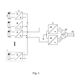
- Fig. 1 shows the basic principle of a first circuit arrangement according to the invention.
- a plurality of subcircuit arrangements (1) is shown, which in turn are represented by an uncontrolled voltage source (2) here of a photovoltaic system and a synchronous converter (4), which is also known as a buck-boost inverter.
- the photovoltaic system (2) in turn consists of a plurality of photovoltaic modules and has a typical, of course, dependent on the sunlight, output voltage between a few hundred to approximately thousand volts.
- the synchronous converter (4) connected to the photovoltaic system (2) has the primary task of increasing the variable output voltage of the photovoltaic system (2) so that an inverter circuit (9) connected to the synchronous converter (4) has a same input voltage as the output voltage allows a possible efficient operation of this inverter circuit (9).
- the inverter circuit (9) itself is designed according to the prior art, here as a parallel connection of two three-phase inverters with a grounded center. This embodiment is only exemplary and not limiting to this embodiment. Furthermore, the inverter circuit is usually connected by means of a suitable transformer (92) to the power grid (90) to be fed.
- a plurality of subcircuit arrangements (1) connected in parallel to one another to a circuit arrangement according to the invention. It is essential here, of course, that the synchronous converters (4) of the subcircuit arrangements (1) also provide the same output voltage at different voltages of the photovoltaic installations (2) supplying them.
- Fig. 2 shows essential components of a second circuit arrangement according to the invention. Shown is analogous to Fig. 1 in turn, a photovoltaic system (2) as an unregulated voltage source which is connected to a synchronous converter (4), in turn consisting of a first capacitor (30), a coil (32), a switching stage (40) and a series circuit of second capacitors (50) , Between the first Connections (42) of the switching stage (40), and thus connected to the outputs of the photovoltaic system (2), the first capacitor (30) is connected. Between this first capacitor (30) and one of the first terminals (42) of the switching stage (40) here the one with positive potential, the coil (32) is provided. The output of the synchronous converter (4) is connected to an inverter circuit (9), which in turn is connected to the power grid (90) to be fed.
- a synchronous converter (4) in turn consisting of a first capacitor (30), a coil (32), a switching stage (40) and a series circuit of second capacitors (50) .
- this control circuit (7) for the autonomous control of the synchronous converter (4).
- this control circuit (7) has first measuring devices (70) for measuring the output voltage and the output current of the photovoltaic system (2), as well as second measuring devices (74) for determining the voltage at the second capacitors (50).
- a DC voltage source (6) is provided which is fed either from the first (30) or one of the second capacitors (50).
- the synchronous converter (4) can operate in buck converter mode and thus the voltage of the connecting line to the inverter circuit (9), which is applied to the second terminals (44) and by means of the inverter circuit (4). 9) can be fed from the power grid (90) in the rectifier mode, reduce to the permitted voltage value of the first capacitor (30).
- the DC voltage source (6) is formed redundantly with two DC voltage sub-sources (60, 62) and the respective DC voltage sub-sources (60, 62) is fed in one of the ways described.
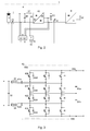
- Fig. 3 shows some components of the circuit arrangement according to the invention according to Fig. 2 in more details. Shown here is the synchronous converter (4) formed with a switching stage (40) with three identical parallel-connected converter stages (400).
- the respective converter stage (400) consists of a series connection of four Power transistors (402, 412, 422, 432) each having antiparallel connected diode (404, 414, 424, 434).
- each of the first power transistor (402) is connected to the second terminal (44a) of the positive polarity of the switching stage, the midpoint between the respective first (402) and second transistor (412) is connected to a first terminal (42a) of positive polarity, the The middle point between respective third (422) and fourth transistors (432) is connected to a first terminal (42b) of negative polarity and the fourth transistor (432) is connected to the second terminal (44b) of negative polarity.
- the three first terminals (42 a / b) of positive and negative polarity of the switching stage (40) are assigned to the three converter stages (400) and each have their own coil (32, 34).
- these respective coils (32, 34) have their own core, but in order to achieve coupling effects it may also be preferable to provide the coils (32, 34) associated with the respective polarities on a common core.
- the two second terminals (44 a / b) of the switching stage (40) are connected to the parallel connection of the second capacitors (50 a / b), wherein the center of this parallel circuit is connected to the centers of the respective converter stages (400).
Landscapes
- Engineering & Computer Science (AREA)
- Power Engineering (AREA)
- Dc-Dc Converters (AREA)
Abstract
Description
- Die Erfindung beschreibt eine Schaltungsanordnung, sowie ein Verfahren zu deren Ansteuerung, zur Erzeugung einer Wechselspannung aus einer Mehrzahl von ungeregelten Spannungsquellen mit zeitlich variabler Ausgangsgleichspannung. Als derartige ungeregelte Spannungsquellen sind Photovoltaikanlagen oder Teile dieser Anlagen bevorzugt. Unter einer Photovoltaikanlage soll hier ausschließlich die Anordnung und elektrische Verbindung einer Mehrzahl von Photovoltaikmodulen verstanden werden, Derartige Photovoltaikmodule sind zu Photovoltaikanlagen zusammengeschlossen und weisen eine bauartbedingte und von der Sonneneinstrahlung abhängige und somit zeitlich langsam variable Ausgangsgleichspannung auf.
- Zu Einspeisung des Ausgangsstroms einer derartigen Photovoltaikanlage in das öffentliche oder ein lokales Stromnetz muss die Ausgangsgleichspannung, mittels einer Wechselrichterschaltung, in eine Wechselspannung konstanter Frequenz und Spannung umgewandelt werden.
- Eine beispielhafte Schaltungsanordnung zur Erzeugung einer derartigen Wechselspannung ist in der
DE 10 2008 034 955 A1 beschrieben. Hier ist eine Stromrichteranordnung offenbart, die eine Photovoltaikanlage mit zeitlich variierender Ausgangsspannung, einen Pegelwandler und einen Wechselrichter aufweist. In dem zugehörigen Verfahren wird der erste und zweite Kondensator des Pegelwandlers unabhängig von der Eingangsspannung mit jeweils dem halben Wert der Sollzwischenkreisspannung geladen. - Für derartige Schaltungsanordnungen gibt es eine Vielzahl vom Anwendungsfall abhängiger und sich teilweise widerstrebender Anforderungen. Beispielhaft soll die Eingangsspannung an der Wechselrichterschaltung möglichst konstant sein, wie auch die Übertragung von der Photovoltaikanlage zur Wechselrichterschaltung mit möglichst hoher Spannung erfolgen soll, um Leitungsverluste klein zu halten. Ebenso soll die gesamte Schaltungsanordnung mit einem hohen Wirkungsgrad arbeiten. Gleichzeitig sollte die Photovoltaikanlage, bzw. deren Photovoltaikmodule, derart betrieben werden, dass sie im Punkt der höchsten Leistungsabgabe (MPP - maximum power point) arbeitet. Hierzu ist eine geeignete Regelung, das sog. MPP- Tracking, erforderlich.
- Der Erfindung liegt die Aufgabe zugrunde eine Schaltungsanordnung mit mindestens einer Teilschaltungsanordnung mit Aufwärtswandlerfunktion, die eine speisende ungeregelte Spannungsquelle aufweist, und ein Verfahren zu deren Ansteuerung vorzustellen wobei die Teilschaltungsanordnung bei Erreichen eines Schwellenwerts der Ausgangsspannung der ungeregelten Spannungsquelle ohne Schaltbefehl einer übergeordneten Steuerlogik selbständig die Aufwärtswandlerfunktion aktiviert.
- Die Aufgabe wird erfindungsgemäß gelöst, durch eine Schaltungsanordnung mit den Merkmalen des Anspruchs 1, sowie durch ein Verfahren gemäß Anspruch 7. Bevorzugte Ausführungsformen sind in den jeweiligen abhängigen Ansprüchen beschrieben.
- Die erfindungsgemäße Schaltungsanordnung weist eine oder eine Mehrzahl parallel geschalteter Teilschaltungsanordnungen zur Speisung mindestens einer Wechselrichterschaltung, die mit einem zugeordneten Stromnetz verbindbar ist. Hierbei besteht jede Teilschaltungsanordnung aus einer ungeregelten Spannungsquelle mit zeitlich variierender Ausgangsgleichspannung, einem Synchronwandler (buck- boostinverter) mit einem ersten Kondensator geschaltet zwischen ersten Anschlüssen einer Schaltstufe und einer Reihenschaltung zweiter Kondensatoren an deren zweiten Anschlüssen, einer Gleichspannungsquelle und einer Regelschaltung zur Ansteuerung des Synchronwandlers.
- Weiterhin ist in mindestens einer Zuleitung zwischen dem ersten Kondensator und den ersten Anschlüssen der Schaltstufe des Synchronwandlers noch mindestens eine Spule vorgesehen. Die Gleichspannungsquelle dient der Versorgung der Regelschaltung und wird vorzugsweise selbst aus dem ersten oder einem der beiden zweiten Kondensatoren versorgt, wozu diese geeignet mit der Gleichspannungsquelle verbunden sind. Alternativ und für eine der Betriebssicherheit dienenden redundanten Ausgestaltung weist diese Gleichspannungsquelle zwei Gleichspannungsteilquellen auf, die zu ihrer jeweiligen Versorgung mit dem ersten bzw. einem der zweiten Kondensatoren verbunden sind.
- Die Regelschaltung ihrerseits weist vorzugsweise eine Mehrzahl von Messeinrichtungen zur Messung der Spannung und des Stroms am Ausgang der ungeregelten Spannungsquelle, des Stromes an den ersten Anschlüssen der Schaltstufe des Synchronwandlers und zur Messung der Spannung an den zweiten Kondensatoren und somit der Ausgangsspannung der Teilschaltungsanordnung auf.
- Die Schaltstufe des Synchronwandlers der erfindungsgemäßen Schaltungsanordnung besteht vorteilhafterweise aus mindestens einer Wandlerstufe, die ihrerseits aus einer Reihenschaltung von vier Leistungstransistoren mit jeweils antiparallel geschalteter Diode besteht. Hierbei ist der erste Leistungstransistor mit dem zweiten Anschluss positiver Polarität verbunden, der Mittelpunkt zwischen ersten und zweiten Transistor ist mit dem ersten Anschluss positiver Polarität verbunden, der Mittelpunkt zwischen dritten und viertem Transistor ist mit dem ersten Anschluss negativer Polarität verbunden und der vierte Transistor ist mit dem zweiten Anschluss negativer Polarität verbunden. Ebenso ist es bevorzugt, wenn der Mittelpunkt zwischen zweitem und drittem Transistor mit dem Mittelpunkt der Reihenschaltung der zweiten Kondensatoren verbunden ist.
- Als Wechselrichterschaltung sind grundsätzlich verschiedene Ausgestaltungen, vorzugsweise als Drei- Phasen- Wechselrichter vorsehbar. Besonders vorteilhaft ist es zwei Drei- Phasen- Wechselrichter parallel anzuordnen und um eine halbe Schaltperiode versetzten anzusteuern. Hierdurch ergibt sich ein vorteilhafter annährend sinusförmiger Strom- und Spannungsverlauf am Ausgang der Wechselrichterschaltung, die ihrerseits entweder direkt oder mittels eines Transformators mit dem Stromnetz verbindbar ist.
- Das zugehörige erfindungsgemäße Verfahren zur Ansteuerung einer derartigen Schaltungsanordnung weist pro Teilschaltungsanordnung, neben dem Stand-by Zustand, in dem nur Überwachungsfunktionen aktiv sind, zwei weitere alternative Betriebsarten auf, deren jeweilige Funktion von einem Schwellenwert der Ausgangsspannung der ungeregelten Spannungsquelle des jeweiligen Teilzweiges abhängt.
- Liegt der Wert der Ausgangsspannung der ungeregelten Spannungsquelle oberhalb dieses Schwellenwerts wird der Synchronwandler als Aufwärtswandler betrieben und lädt somit die zweiten Kondensatoren und legt einen, vorzugsweise bereits in der Ansteuerschaltung hinterlegten vordefinierten, Sollwert an die Ausgänge des Synchronwandlers an. Eine Mehrzahl gleichartiger Teilschaltungsanordnungen kann somit parallel geschaltet werden, da alle aktiven Teilschaltungen die gleiche Ausgangsspannung aufweisen, ohne dass ein übergeordnet Steuerlogik hierauf notwendigerweise direkt und fortlaufen Einfluss nimmt.
- Liegt der Wert der Ausgangsspannung der ungeregelten Spannungsquelle unterhalb dieses Schwellenwerts und ist der erste Kondensator nicht annährend vollständig geladen wird der Synchronwandler als Abwärtswandler betrieben und lädt somit den ersten Kondensator beispielhaft aus dem Stromnetz. Hierzu liefert der Wechselrichter eine Gleichspannung an den zweiten Anschlüssen der Schaltstufe des Synchronwandlers, der hieraus im Abwärtswandlerbetrieb die notwendige Spannung an den ersten Kondensator anlegt.
- Aus der zweitgenannten Betriebsart, oder auch aus dem Stand-by Zustand mit geladenem ersten Kondensator, schaltet die Ansteuerschaltung den Synchronwandler unmittelbar in die erstgenannte Betriebsart sobald der Schwellenwert überschritten wird. Dieses Umschalten kann autonom erfolgen, da die notwendigen Messeinrichtungen zur Messung der Spannung und des Stromes der ungeregelten Spannungsquelle durch die aus der Gleichspannungsquelle gespeisten Ansteuerschaltung jederzeit möglich ist.
- Die Gleichspannungsquelle ihrerseits wird hierzu kontinuierlich oder diskontinuierlich mittels des ersten und / oder eines zweiten Kondensators geladen und kann somit die Ansteuerschaltung des Synchronwandlers jederzeit versorgen. Zusätzlich kann, falls die ungeregelte Spannungsquelle eine Photovoltaikanlage ist, die Ansteuerschaltung das MPP- Tracking dieser Photovoltaikanlage ausführen.
- Die erfinderische Lösung wird an Hand der Ausführungsbeispiele der
Fig. 1 bis 3 weiter erläutert. -
Fig. 1 zeigt das Grundprinzip einer ersten erfindungsgemäßen Schaltungsanordnung. -
Fig. 2 zeigt wesentliche Komponenten einer zweiten erfindungsgemäßen Schaltungsanordnung. -
Fig. 3 zeigt einige Komponenten der erfindungsgemäßen Schaltungsanordnung gemäßFig. 2 in weiteren Details. -
Fig. 1 zeigt das Grundprinzip einer ersten erfindungsgemäßen Schaltungsanordnung. Hierzu ist eine Mehrzahl von Teilschaltungsanordnungen (1) dargestellt, die ihrerseits aus einer ungeregelten Spannungsquelle (2) hier einer Photovoltaikanlage und einem Synchronwandler (4), der auch als buck- boost- inverter bekannt ist, dargestellt. Die Photovoltaikanlage (2) ihrerseits besteht aus einer Mehrzahl von Photovoltaikmodulen und weist eine typische, selbstverständlich von der Sonneneinstrahlung abhängige, Ausgangsspannung zwischen einigen hundert bis annährend tausend Volt auf. - Der mit der Photovoltaikanlage (2) verbundene Synchronwandler (4) hat die primäre Aufgabe die variable Ausgangsspannung der Photovoltaikanlage (2) derart zu erhöhen, dass eine mit dem Synchronwandler (4) verbundene Wechselrichterschaltung (9) eine mit der Ausgangsspannung gleiche Eingangsspannung aufweist, die einen mögliches effizient Betrieb dieser Wechselrichterschaltung (9) gestattet. Die Wechselrichterschaltung (9) selbst ist gemäß dem Stand der Technik ausgestaltet, hier als Parallelschaltung zweier Drei- Phasen Wechselrichter mit geerdetem Mittelpunkt. Diese Ausgestaltung ist nur beispielhaft und nicht beschränkend auf diese Ausführungsform. Weiterhin ist die Wechselrichterschaltung üblicherweise mittels eines geeigneten Transformators (92) mit dem zu speisenden Stromnetz (90) verbunden.
- Vorteilhafterweise sind hier eine Mehrzahl von Teilschaltungsanordnungen (1) zu einer erfindungsgemäßen Schaltungsanordnung parallel miteinander verschaltet. Wesentlich ist hierbei selbstverständlich, dass die Synchronwandler (4) der Teilschaltungsanordnungen (1) auch bei unterschiedlicher Spannung der sie versorgenden Photovoltaikanlagen (2) jeweils die gleiche Ausgangsspannung zur Verfügung stellen.
-
Fig. 2 zeigt wesentliche Komponenten einer zweiten erfindungsgemäßen Schaltungsanordnung. Dargestellt ist analog zuFig. 1 wiederum eine Photovoltaikanlage (2) als ungeregelte Spannungsquelle, die mit einem Synchronwandler (4), seinerseits bestehend aus eine ersten Kondensator (30), einer Spule (32), einer Schaltstufe (40) und einer Reihenschaltung zweiter Kondensatoren (50), verbunden ist. Zwischen den ersten Anschüssen (42) der Schaltstufe (40), und somit mit den Ausgängen der Photovoltaikanlage (2) verbunden ist der erste Kondensator (30) geschaltet. Zwischen diesem ersten Kondensator (30) und einem der ersten Anschlüsse (42) der Schaltstufe (40) hier demjenigen mit positivem Potential ist die Spule (32) vorgesehen. Der Ausgang des Synchronwandlers (4) ist mit einer Wechselrichterschaltung (9) verbunden, die ihrerseits mit dem zu speisenden Stromnetz (90) verbunden ist. - Weiterhin dargestellt ist eine Regelschaltung (7) zur autonomen Ansteuerung des Synchronwandlers (4). Diese Regelschaltung (7) weist hierzu erste Messeinrichtungen (70) zur Messung der Ausgangsspannung und des Ausgangsstroms der Photovoltaikanlage (2), ebenso wie zweite Messeinrichtungen (74) zur Bestimmung der Spannung an den zweiten Kondensatoren (50), auf.
- Zur Energieversorgung dieser Regelschaltung (7) ist eine Gleichspannungsquelle (6) vorgesehen, die entweder aus dem ersten (30) oder einem der zweiten Kondensatoren (50) gespeist wird. Zur Versorgung der Gleichspannungsquelle (6) aus dem ersten Kondensator (30) kann der Synchronwandler (4) im Abwärtswandlerbetrieb arbeiten und somit die Spannung der Verbindungsleitung zur Wechselrichterschaltung (9), die an den zweiten Anschlüssen (44) anliegt und die mittels der Wechselrichterschaltung (9) im Gleichrichterbetrieb aus dem Stromnetz (90) gespeist sein kann, auf den erlaubten Spannungswert des ersten Kondensators (30) reduzieren. Es ist allerdings besonders bevorzugt, wie hier dargestellt, wenn die Gleichspannungsquelle (6) redundant mit zwei Gleichspannungsteilquellen (60, 62) ausgebildet ist und die jeweiligen Gleichspannungsteilquellen (60, 62) auf jeweils eine der beschriebenen Weisen gespeist wird.
- Besonders vorteilhaft bei dieser Ausgestaltung der Schaltungsanordnung ist, dass diese nicht notwendigerweise eine Verbindung zu einer übergeordneten, nicht dargestellten, Steuerlogik benötigt, da sie autonom arbeiten kann. Dies bedeutet, dass die Photovoltaikanlage (2) von der, aus der Gleichspannungsquelle (6) gespeisten, Regelschaltung (7) überwacht wird und bei ausreichender Spannung an den Ausgängen der Photovoltaikanlage (2) der Synchronwandler (4) in den Aufwärtswandlerbetrieb geht und die notwendige Ausgangsspannung zur Verfügung stellt.
-
Fig. 3 zeigt einige Komponenten der erfindungsgemäßen Schaltungsanordnung gemäßFig. 2 in weiteren Details. Dargestellt ist hier der Synchronwandler (4) ausgebildet mit einer Schaltstufe (40) mit drei identischen parallel geschalteten Wandlerstufen (400). Die jeweilige Wandlerstufe (400) besteht aus einer Reihenschaltung von vier Leistungstransistoren (402, 412, 422, 432) mit jeweils antiparallel geschalteter Diode (404, 414, 424, 434). Hierbei ist jeweils der erste Leistungstransistor (402) mit dem zweiten Anschluss (44a) positiver Polarität der Schaltstufe verbunden ist, der Mittelpunkt zwischen jeweiligem ersten (402) und zweiten Transistor (412) ist mit einem ersten Anschluss (42a) positiver Polarität verbunden, der Mittelpunkt zwischen jeweiligem dritten (422) und viertem Transistor (432) ist mit einem ersten Anschluss (42b) negativer Polarität verbunden und der vierte Transistor (432) ist mit dem zweiten Anschluss (44b) negativer Polarität verbunden. - Die drei ersten Anschlüsse (42 a/b) positiver und negativer Polarität der Schaltstufe (40) sind hierbei den drei Wandlerstufen (400) zugeordnet und weisen jeweils eine eigene Spule (32, 34) auf. Üblicherweise weisen diese jeweiligen Spulen (32, 34) einen eigenen Kern auf, es kann allerdings um Kopplungseffekte zu erzielen auch bevorzugt sein die den jeweiligen Polaritäten zugeordneten Spulen (32 ,34) auf einem gemeinsamen Kern vorzusehen.
- Die beiden zweiten Anschlüsse (44 a/b) der Schaltstufe (40) sind mit der Parallelschaltung der zweiten Kondensatoren (50 a/b) verbunden, wobei der Mittelpunkt dieser Parallelschaltung mit den Mittelpunkten der jeweiligen Wandlerstufen (400) verbunden ist.
Claims (9)
- Schaltungsanordnung mit einer oder einer Mehrzahl parallel geschalteter Teilschaltungsanordnungen (1) zur Speisung mindestens einer Wechselrichterschaltung (9), die mit einem Stromnetz (90) verbindbar ist, wobei eine Teilschaltungsanordnung (1) besteht aus einer ungeregelten Spannungsquelle (2) mit zeitlich variierender Ausgangsgleichspannung, einem Synchronwandler (4) mit einem ersten Kondensator (30) geschaltet zwischen den ersten Anschlüssen (42 a/b) einer Schaltstufe (40) des Synchronwandlers und einer Reihenschaltung zweiter Kondensatoren (50 a/b) an deren zweiten Anschlüssen (44 a/b), wobei in mindestens einer Zuleitung zwischen dem ersten Kondensator (30) und den ersten Anschlüssen (42 a/b) noch mindestens eine Spule (32, 34) vorgesehen ist, mit einer Gleichspannungsquelle (6) zur Versorgung einer Regelschaltung (7) zur Ansteuerung des Synchronwandlers (4) mit einer Mehrzahl von Messeinrichtungen (70, 74).
- Schaltungsanordnung nach Anspruch 1, wobei
die Schaltstufe (40) des Synchronwandlers aus mindestens einer Wandlerstufe (400) besteht, die ihrerseits aus einer Reihenschaltung von vier Leistungstransistoren (402, 412, 422, 432) mit jeweils antiparallel geschalteter Diode (404, 414, 424, 434) besteht, wobei der erste Leistungstransistor (402) mit einem zweiten Anschluss (44a) positiver Polarität verbunden ist, der Mittelpunkt zwischen ersten (402) und zweiten Leistungstransistor (412) mit einem ersten Anschluss (42a) positiver Polarität verbunden ist, der Mittelpunkt zwischen dritten (422) und vierten Leistungstransistor (432) mit dem ersten Anschluss (42b) negativer Polarität verbunden ist und der vierte Leistungstransistor (432) mit dem zweiten Anschluss (44b) negativer Polarität verbunden ist. - Schaltungsanordnung nach Anspruch 2, wobei
bei einer Mehrzahl von Wandlerstufen (400) die zugeordneten Spulen jeweils auf einem eigenen Kern, oder gekoppelt auf einem gemeinsamen Kern angeordnet sind. - Schaltungsanordnung nach Anspruch 2, wobei
der Mittelpunkt zwischen zweitem (412) und drittem Leistungstransistor (422) mit dem Mittelpunkt der Reihenschaltung der zweiten Kondensatoren (50 a/b) verbunden ist. - Schaltungsanordnung nach Anspruch 1, wobei
die Gleichspannungsquelle (6) zu ihrer Versorgung mit dem ersten (30) oder einem der beiden zweiten Kondensatoren (50 a/b) verbunden ist. - Schaltungsanordnung nach Anspruch 1, wobei
die Gleichspannungsquelle (6) redundant (60, 62) ausgeführt ist und zu ihrer Versorgung und mit dem ersten (30) und einem der zweiten Kondensatoren (50 a/b) verbunden ist. - Verfahren zur Ansteuerung einer Schaltungsanordnung nach einem der vorhergehenden Ansprüche, wobei der Synchronwandler (4) der mindestens eine Teilschaltungsanordnung (1) mindestens zwei Betriebsarten aufweist,
eine erste Betriebsart als Aufwärtswandler, wenn der Wert der Ausgangsspannung der ungeregelten Spannungsquelle (2), einen Schwellenwert überschreitet und somit die Wechselrichterschaltung (9) mit der notwendigen Eingangsspannung versorgt wird, und
eine zweite Betriebsart als Abwärtswandler, wenn der Wert einer Ausgangsspannung der ungeregelten Spannungsquelle (2) einen Schwellenwert unterschreitet oder keine Ausgangsspannung von der ungeregelten Spannungsquelle (2) anliegt, wobei der erste Kondensator (30) aus der an den zweiten Anschlüssen (44 a/b) anliegenden Gleichspannung geladen wird und
wobei die Gleichspannungsquelle (6) in beiden Betriebsarten mittels des ersten (30) und / oder einem zweiten Kondensator (50 a/b) geladen wird und ihrerseits die Regelschaltung (7) des Synchronwandlers (4) versorgt und somit der Synchronwandler (4) bei erreichen des Schwellenwertes autonom und unmittelbar von der zweiten in die erste Betriebsart umschaltet. - Verfahren nach Anspruch 7, wobei
zur Regelung der Betriebsart des Synchronwandlers (4) mittels der Messeinrichtungen (70, 74) die Spannung und der Strom am Ausgang der ungeregelten Spannungsquelle (2) und die jeweilige Spannung an mindestens einem der beiden zweiten Kondensatoren (50 a/b) gemessen wird. - Verfahren nach Anspruch 8, wobei
die Regelschaltung (7) zusätzlich das MPP- Tracking einer als Photovoltaikanlage ausgestalteten ungeregelten Spannungsquelle regelt.
Applications Claiming Priority (1)
| Application Number | Priority Date | Filing Date | Title |
|---|---|---|---|
| US33440210P | 2010-05-31 | 2010-05-31 |
Publications (3)
| Publication Number | Publication Date |
|---|---|
| EP2395639A2 true EP2395639A2 (de) | 2011-12-14 |
| EP2395639A3 EP2395639A3 (de) | 2015-03-18 |
| EP2395639B1 EP2395639B1 (de) | 2020-04-01 |
Family
ID=44862225
Family Applications (1)
| Application Number | Title | Priority Date | Filing Date |
|---|---|---|---|
| EP11162192.6A Active EP2395639B1 (de) | 2010-05-31 | 2011-04-13 | Schaltungsanordnung und Verfahren zur Erzeugung einer Wechselspannung aus mindestens einer Spannungsquelle mit zeitlich variabler Ausgangsgleichspannung |
Country Status (2)
| Country | Link |
|---|---|
| US (1) | US9059643B2 (de) |
| EP (1) | EP2395639B1 (de) |
Cited By (1)
| Publication number | Priority date | Publication date | Assignee | Title |
|---|---|---|---|---|
| DE102011086829A1 (de) * | 2011-11-22 | 2013-05-23 | Continental Automotive Gmbh | Bordnetz und Verfahren zum Betreiben eines Bordnetzes |
Families Citing this family (9)
| Publication number | Priority date | Publication date | Assignee | Title |
|---|---|---|---|---|
| US9704161B1 (en) | 2008-06-27 | 2017-07-11 | Amazon Technologies, Inc. | Providing information without authentication |
| US8788945B1 (en) * | 2008-06-30 | 2014-07-22 | Amazon Technologies, Inc. | Automatic approval |
| US9449319B1 (en) | 2008-06-30 | 2016-09-20 | Amazon Technologies, Inc. | Conducting transactions with dynamic passwords |
| EP2493062B1 (de) * | 2011-02-28 | 2015-04-15 | SEMIKRON Elektronik GmbH & Co. KG | DC-DC Wandlerzelle, hieraus aufgebaute rückspeisefähige DC-DC Wandlerschaltung und Verfahren zu deren Betrieb |
| CN102931829B (zh) * | 2012-11-09 | 2015-11-25 | 华为技术有限公司 | 功率因数校正电路以及电源电路 |
| US9502962B2 (en) | 2012-11-09 | 2016-11-22 | Huawei Technologies Co., Ltd. | Power factor correction circuit and power supply circuit |
| US9602025B2 (en) * | 2013-07-12 | 2017-03-21 | Infineon Technologies Austria Ag | Multiphase power converter circuit and method |
| EP3297150A1 (de) * | 2016-09-15 | 2018-03-21 | Siemens Aktiengesellschaft | Regelung von phasenströmen parallel geschalteter wechselrichter |
| DE102017131042A1 (de) | 2017-12-21 | 2019-06-27 | Sma Solar Technology Ag | Umrichter mit mindestens einem wandlermodul mit drei brückenzweigen, verfahren zum betreiben und verwendung eines solchen umrichters |
Citations (1)
| Publication number | Priority date | Publication date | Assignee | Title |
|---|---|---|---|---|
| DE102008034955A1 (de) | 2008-07-26 | 2010-02-04 | Semikron Elektronik Gmbh & Co. Kg | Stromrichteranordnung für Solarstromanlagen und Ansteuerverfahren hierzu |
Family Cites Families (7)
| Publication number | Priority date | Publication date | Assignee | Title |
|---|---|---|---|---|
| SE9701060L (sv) * | 1997-03-24 | 1998-03-04 | Asea Brown Boveri | Anläggning för överföring av elektrisk effekt |
| US6809942B2 (en) * | 2001-06-29 | 2004-10-26 | Sanyo Electric Co., Ltd. | System interconnection electric power generator and control method therefor |
| WO2007110913A1 (ja) * | 2006-03-27 | 2007-10-04 | Mitsubishi Denki Kabushiki Kaisha | 系統連系インバータ装置 |
| US7646182B2 (en) * | 2006-03-29 | 2010-01-12 | Mitsubishi Electric Corporation | Power supply apparatus |
| JP5124114B2 (ja) * | 2006-08-28 | 2013-01-23 | シャープ株式会社 | 蓄電機能を有するパワーコンディショナ |
| JP4886487B2 (ja) * | 2006-12-01 | 2012-02-29 | 本田技研工業株式会社 | 多入出力電力変換器及び燃料電池車 |
| US8427010B2 (en) * | 2009-05-29 | 2013-04-23 | General Electric Company | DC-to-AC power conversion system and method |
-
2011
- 2011-04-13 EP EP11162192.6A patent/EP2395639B1/de active Active
- 2011-05-13 US US13/107,600 patent/US9059643B2/en active Active
Patent Citations (1)
| Publication number | Priority date | Publication date | Assignee | Title |
|---|---|---|---|---|
| DE102008034955A1 (de) | 2008-07-26 | 2010-02-04 | Semikron Elektronik Gmbh & Co. Kg | Stromrichteranordnung für Solarstromanlagen und Ansteuerverfahren hierzu |
Cited By (2)
| Publication number | Priority date | Publication date | Assignee | Title |
|---|---|---|---|---|
| DE102011086829A1 (de) * | 2011-11-22 | 2013-05-23 | Continental Automotive Gmbh | Bordnetz und Verfahren zum Betreiben eines Bordnetzes |
| US10000168B2 (en) | 2011-11-22 | 2018-06-19 | Continental Automotive Gmbh | Vehicle electrical system and method for operating a vehicle electrical system |
Also Published As
| Publication number | Publication date |
|---|---|
| US9059643B2 (en) | 2015-06-16 |
| EP2395639A3 (de) | 2015-03-18 |
| EP2395639B1 (de) | 2020-04-01 |
| US20110304214A1 (en) | 2011-12-15 |
Similar Documents
| Publication | Publication Date | Title |
|---|---|---|
| EP2395639B1 (de) | Schaltungsanordnung und Verfahren zur Erzeugung einer Wechselspannung aus mindestens einer Spannungsquelle mit zeitlich variabler Ausgangsgleichspannung | |
| EP2596980B1 (de) | Mehrpunkt-Stromrichter mit Bremschopper | |
| DE102014212934A1 (de) | Vorrichtung und Verfahren zum Ladezustandsausgleich eines Energiespeichersystems | |
| DE112015002616B4 (de) | Stromrichteranordnung | |
| EP3022835A1 (de) | Wechselrichter mit mindestens zwei gleichstromeingängen, photovoltaikanlage mit einem derartigen wechselrichter und verfahren zur ansteuerung eines wechselrichters | |
| DE112016004961T5 (de) | Mehrphasenwandler | |
| DE102018221519B4 (de) | Fahrzeugseitige Ladevorrichtung | |
| EP3467990A1 (de) | Energiebereitstellungseinrichtung zum bereitstellen elektrischer energie für wenigstens ein endgerät sowie verfahren zum betreiben einer energiebereitstellungseinrichtung | |
| EP2369733B1 (de) | Schaltungsanordnung und Verfahren zur Erzeugung einer Wechselspannung aus einer Mehrzahl von Spannungsquellen mit zeitlich variabler Ausgangsgleichspannung | |
| EP3290254A1 (de) | Bidirektionaler bordnetzumrichter und verfahren zu dessen betrieb | |
| DE102015111553A1 (de) | Vorrichtung und Verfahren zur induktiven Übertragung elektrischer Energie | |
| WO2021001406A1 (de) | Fahrzeugbordnetz | |
| DE102014013039A1 (de) | Vorrichtung für ein Kraftfahrzeug zum galvanisch entkoppelten Übertragen einer elektrischen Spannung | |
| DE102019008340A1 (de) | Stromversorgung | |
| WO2013135578A1 (de) | Schaltungsanordnung und verfahren zum wandeln und anpassen einer gleichspannung, photovoltaikanlage | |
| DE102013212692A1 (de) | Energiespeichereinrichtung mit Gleichspannungsversorgungsschaltung | |
| DE102012206801A1 (de) | Schaltung mit einer stromrichterschaltung und verfahren zur leistungsanpassung | |
| EP3363091B1 (de) | Vorrichtung und verfahren zum steuern eines lastflusses in einem wechselspannungsnetz | |
| EP2826126B1 (de) | Leistungselektronische anordnung mit symmetrierung eines spannungsknotens im zwischenkreis | |
| EP2774255B1 (de) | Spannungswandler mit einer ersten parallelschaltung | |
| EP3331118B1 (de) | Anlage zum übertragen elektrischer leistung | |
| DE102014212930B3 (de) | Vorrichtung zum Bereitstellen einer elektrischen Spannung sowie Antriebsanordnung und Verfahren | |
| EP2849327B1 (de) | Variabler Tiefsetzer und Batterieladestation mit einem solchen Tiefsetzer | |
| EP4070444B1 (de) | Verfahren zum betreiben eines wechselrichters und wechselrichter zur durchführung des verfahrens | |
| EP2928055B1 (de) | Modularer Stromrichter und Verfahren zur Erzeugung einer sinusförmigen Ausgangsspannung mit reduziertem Oberschwingungsgehalt |
Legal Events
| Date | Code | Title | Description |
|---|---|---|---|
| AK | Designated contracting states |
Kind code of ref document: A2 Designated state(s): AL AT BE BG CH CY CZ DE DK EE ES FI FR GB GR HR HU IE IS IT LI LT LU LV MC MK MT NL NO PL PT RO RS SE SI SK SM TR |
|
| AX | Request for extension of the european patent |
Extension state: BA ME |
|
| PUAI | Public reference made under article 153(3) epc to a published international application that has entered the european phase |
Free format text: ORIGINAL CODE: 0009012 |
|
| PUAL | Search report despatched |
Free format text: ORIGINAL CODE: 0009013 |
|
| AK | Designated contracting states |
Kind code of ref document: A3 Designated state(s): AL AT BE BG CH CY CZ DE DK EE ES FI FR GB GR HR HU IE IS IT LI LT LU LV MC MK MT NL NO PL PT RO RS SE SI SK SM TR |
|
| AX | Request for extension of the european patent |
Extension state: BA ME |
|
| RIC1 | Information provided on ipc code assigned before grant |
Ipc: H02M 1/00 20070101ALN20150212BHEP Ipc: H02M 3/158 20060101AFI20150212BHEP Ipc: H02M 7/81 20060101ALI20150212BHEP Ipc: H02J 3/38 20060101ALI20150212BHEP |
|
| 17P | Request for examination filed |
Effective date: 20150918 |
|
| STAA | Information on the status of an ep patent application or granted ep patent |
Free format text: STATUS: EXAMINATION IS IN PROGRESS |
|
| 17Q | First examination report despatched |
Effective date: 20171124 |
|
| RIC1 | Information provided on ipc code assigned before grant |
Ipc: H02M 7/81 20060101ALI20190919BHEP Ipc: H02M 3/158 20060101AFI20190919BHEP Ipc: H02M 1/00 20060101ALN20190919BHEP Ipc: H02J 3/38 20060101ALI20190919BHEP |
|
| RIC1 | Information provided on ipc code assigned before grant |
Ipc: H02M 3/158 20060101AFI20190924BHEP Ipc: H02M 7/81 20060101ALI20190924BHEP Ipc: H02J 3/38 20060101ALI20190924BHEP Ipc: H02M 1/00 20060101ALN20190924BHEP |
|
| GRAP | Despatch of communication of intention to grant a patent |
Free format text: ORIGINAL CODE: EPIDOSNIGR1 |
|
| STAA | Information on the status of an ep patent application or granted ep patent |
Free format text: STATUS: GRANT OF PATENT IS INTENDED |
|
| INTG | Intention to grant announced |
Effective date: 20191111 |
|
| GRAS | Grant fee paid |
Free format text: ORIGINAL CODE: EPIDOSNIGR3 |
|
| GRAA | (expected) grant |
Free format text: ORIGINAL CODE: 0009210 |
|
| STAA | Information on the status of an ep patent application or granted ep patent |
Free format text: STATUS: THE PATENT HAS BEEN GRANTED |
|
| AK | Designated contracting states |
Kind code of ref document: B1 Designated state(s): AL AT BE BG CH CY CZ DE DK EE ES FI FR GB GR HR HU IE IS IT LI LT LU LV MC MK MT NL NO PL PT RO RS SE SI SK SM TR |
|
| REG | Reference to a national code |
Ref country code: GB Ref legal event code: FG4D Free format text: NOT ENGLISH |
|
| REG | Reference to a national code |
Ref country code: CH Ref legal event code: EP Ref country code: AT Ref legal event code: REF Ref document number: 1252658 Country of ref document: AT Kind code of ref document: T Effective date: 20200415 |
|
| REG | Reference to a national code |
Ref country code: DE Ref legal event code: R096 Ref document number: 502011016572 Country of ref document: DE |
|
| REG | Reference to a national code |
Ref country code: IE Ref legal event code: FG4D Free format text: LANGUAGE OF EP DOCUMENT: GERMAN |
|
| PG25 | Lapsed in a contracting state [announced via postgrant information from national office to epo] |
Ref country code: BG Free format text: LAPSE BECAUSE OF FAILURE TO SUBMIT A TRANSLATION OF THE DESCRIPTION OR TO PAY THE FEE WITHIN THE PRESCRIBED TIME-LIMIT Effective date: 20200701 |
|
| REG | Reference to a national code |
Ref country code: NL Ref legal event code: MP Effective date: 20200401 |
|
| REG | Reference to a national code |
Ref country code: LT Ref legal event code: MG4D |
|
| PG25 | Lapsed in a contracting state [announced via postgrant information from national office to epo] |
Ref country code: CZ Free format text: LAPSE BECAUSE OF FAILURE TO SUBMIT A TRANSLATION OF THE DESCRIPTION OR TO PAY THE FEE WITHIN THE PRESCRIBED TIME-LIMIT Effective date: 20200401 Ref country code: IS Free format text: LAPSE BECAUSE OF FAILURE TO SUBMIT A TRANSLATION OF THE DESCRIPTION OR TO PAY THE FEE WITHIN THE PRESCRIBED TIME-LIMIT Effective date: 20200801 Ref country code: NO Free format text: LAPSE BECAUSE OF FAILURE TO SUBMIT A TRANSLATION OF THE DESCRIPTION OR TO PAY THE FEE WITHIN THE PRESCRIBED TIME-LIMIT Effective date: 20200701 Ref country code: FI Free format text: LAPSE BECAUSE OF FAILURE TO SUBMIT A TRANSLATION OF THE DESCRIPTION OR TO PAY THE FEE WITHIN THE PRESCRIBED TIME-LIMIT Effective date: 20200401 Ref country code: NL Free format text: LAPSE BECAUSE OF FAILURE TO SUBMIT A TRANSLATION OF THE DESCRIPTION OR TO PAY THE FEE WITHIN THE PRESCRIBED TIME-LIMIT Effective date: 20200401 Ref country code: SE Free format text: LAPSE BECAUSE OF FAILURE TO SUBMIT A TRANSLATION OF THE DESCRIPTION OR TO PAY THE FEE WITHIN THE PRESCRIBED TIME-LIMIT Effective date: 20200401 Ref country code: GR Free format text: LAPSE BECAUSE OF FAILURE TO SUBMIT A TRANSLATION OF THE DESCRIPTION OR TO PAY THE FEE WITHIN THE PRESCRIBED TIME-LIMIT Effective date: 20200702 Ref country code: PT Free format text: LAPSE BECAUSE OF FAILURE TO SUBMIT A TRANSLATION OF THE DESCRIPTION OR TO PAY THE FEE WITHIN THE PRESCRIBED TIME-LIMIT Effective date: 20200817 Ref country code: LT Free format text: LAPSE BECAUSE OF FAILURE TO SUBMIT A TRANSLATION OF THE DESCRIPTION OR TO PAY THE FEE WITHIN THE PRESCRIBED TIME-LIMIT Effective date: 20200401 |
|
| PG25 | Lapsed in a contracting state [announced via postgrant information from national office to epo] |
Ref country code: RS Free format text: LAPSE BECAUSE OF FAILURE TO SUBMIT A TRANSLATION OF THE DESCRIPTION OR TO PAY THE FEE WITHIN THE PRESCRIBED TIME-LIMIT Effective date: 20200401 Ref country code: LV Free format text: LAPSE BECAUSE OF FAILURE TO SUBMIT A TRANSLATION OF THE DESCRIPTION OR TO PAY THE FEE WITHIN THE PRESCRIBED TIME-LIMIT Effective date: 20200401 Ref country code: HR Free format text: LAPSE BECAUSE OF FAILURE TO SUBMIT A TRANSLATION OF THE DESCRIPTION OR TO PAY THE FEE WITHIN THE PRESCRIBED TIME-LIMIT Effective date: 20200401 |
|
| REG | Reference to a national code |
Ref country code: CH Ref legal event code: PL |
|
| PG25 | Lapsed in a contracting state [announced via postgrant information from national office to epo] |
Ref country code: AL Free format text: LAPSE BECAUSE OF FAILURE TO SUBMIT A TRANSLATION OF THE DESCRIPTION OR TO PAY THE FEE WITHIN THE PRESCRIBED TIME-LIMIT Effective date: 20200401 |
|
| REG | Reference to a national code |
Ref country code: DE Ref legal event code: R097 Ref document number: 502011016572 Country of ref document: DE |
|
| PG25 | Lapsed in a contracting state [announced via postgrant information from national office to epo] |
Ref country code: DK Free format text: LAPSE BECAUSE OF FAILURE TO SUBMIT A TRANSLATION OF THE DESCRIPTION OR TO PAY THE FEE WITHIN THE PRESCRIBED TIME-LIMIT Effective date: 20200401 Ref country code: LU Free format text: LAPSE BECAUSE OF NON-PAYMENT OF DUE FEES Effective date: 20200413 Ref country code: EE Free format text: LAPSE BECAUSE OF FAILURE TO SUBMIT A TRANSLATION OF THE DESCRIPTION OR TO PAY THE FEE WITHIN THE PRESCRIBED TIME-LIMIT Effective date: 20200401 Ref country code: IT Free format text: LAPSE BECAUSE OF FAILURE TO SUBMIT A TRANSLATION OF THE DESCRIPTION OR TO PAY THE FEE WITHIN THE PRESCRIBED TIME-LIMIT Effective date: 20200401 Ref country code: SM Free format text: LAPSE BECAUSE OF FAILURE TO SUBMIT A TRANSLATION OF THE DESCRIPTION OR TO PAY THE FEE WITHIN THE PRESCRIBED TIME-LIMIT Effective date: 20200401 Ref country code: LI Free format text: LAPSE BECAUSE OF NON-PAYMENT OF DUE FEES Effective date: 20200430 Ref country code: CH Free format text: LAPSE BECAUSE OF NON-PAYMENT OF DUE FEES Effective date: 20200430 Ref country code: RO Free format text: LAPSE BECAUSE OF FAILURE TO SUBMIT A TRANSLATION OF THE DESCRIPTION OR TO PAY THE FEE WITHIN THE PRESCRIBED TIME-LIMIT Effective date: 20200401 Ref country code: MC Free format text: LAPSE BECAUSE OF FAILURE TO SUBMIT A TRANSLATION OF THE DESCRIPTION OR TO PAY THE FEE WITHIN THE PRESCRIBED TIME-LIMIT Effective date: 20200401 Ref country code: ES Free format text: LAPSE BECAUSE OF FAILURE TO SUBMIT A TRANSLATION OF THE DESCRIPTION OR TO PAY THE FEE WITHIN THE PRESCRIBED TIME-LIMIT Effective date: 20200401 |
|
| REG | Reference to a national code |
Ref country code: BE Ref legal event code: MM Effective date: 20200430 |
|
| PLBE | No opposition filed within time limit |
Free format text: ORIGINAL CODE: 0009261 |
|
| STAA | Information on the status of an ep patent application or granted ep patent |
Free format text: STATUS: NO OPPOSITION FILED WITHIN TIME LIMIT |
|
| PG25 | Lapsed in a contracting state [announced via postgrant information from national office to epo] |
Ref country code: PL Free format text: LAPSE BECAUSE OF FAILURE TO SUBMIT A TRANSLATION OF THE DESCRIPTION OR TO PAY THE FEE WITHIN THE PRESCRIBED TIME-LIMIT Effective date: 20200401 Ref country code: SK Free format text: LAPSE BECAUSE OF FAILURE TO SUBMIT A TRANSLATION OF THE DESCRIPTION OR TO PAY THE FEE WITHIN THE PRESCRIBED TIME-LIMIT Effective date: 20200401 Ref country code: BE Free format text: LAPSE BECAUSE OF NON-PAYMENT OF DUE FEES Effective date: 20200430 |
|
| 26N | No opposition filed |
Effective date: 20210112 |
|
| GBPC | Gb: european patent ceased through non-payment of renewal fee |
Effective date: 20200701 |
|
| PG25 | Lapsed in a contracting state [announced via postgrant information from national office to epo] |
Ref country code: IE Free format text: LAPSE BECAUSE OF NON-PAYMENT OF DUE FEES Effective date: 20200413 Ref country code: GB Free format text: LAPSE BECAUSE OF NON-PAYMENT OF DUE FEES Effective date: 20200701 Ref country code: FR Free format text: LAPSE BECAUSE OF NON-PAYMENT OF DUE FEES Effective date: 20200601 |
|
| PG25 | Lapsed in a contracting state [announced via postgrant information from national office to epo] |
Ref country code: SI Free format text: LAPSE BECAUSE OF FAILURE TO SUBMIT A TRANSLATION OF THE DESCRIPTION OR TO PAY THE FEE WITHIN THE PRESCRIBED TIME-LIMIT Effective date: 20200401 |
|
| REG | Reference to a national code |
Ref country code: AT Ref legal event code: MM01 Ref document number: 1252658 Country of ref document: AT Kind code of ref document: T Effective date: 20200413 |
|
| PG25 | Lapsed in a contracting state [announced via postgrant information from national office to epo] |
Ref country code: AT Free format text: LAPSE BECAUSE OF NON-PAYMENT OF DUE FEES Effective date: 20200413 |
|
| PG25 | Lapsed in a contracting state [announced via postgrant information from national office to epo] |
Ref country code: TR Free format text: LAPSE BECAUSE OF FAILURE TO SUBMIT A TRANSLATION OF THE DESCRIPTION OR TO PAY THE FEE WITHIN THE PRESCRIBED TIME-LIMIT Effective date: 20200401 Ref country code: MT Free format text: LAPSE BECAUSE OF FAILURE TO SUBMIT A TRANSLATION OF THE DESCRIPTION OR TO PAY THE FEE WITHIN THE PRESCRIBED TIME-LIMIT Effective date: 20200401 Ref country code: CY Free format text: LAPSE BECAUSE OF FAILURE TO SUBMIT A TRANSLATION OF THE DESCRIPTION OR TO PAY THE FEE WITHIN THE PRESCRIBED TIME-LIMIT Effective date: 20200401 |
|
| PG25 | Lapsed in a contracting state [announced via postgrant information from national office to epo] |
Ref country code: MK Free format text: LAPSE BECAUSE OF FAILURE TO SUBMIT A TRANSLATION OF THE DESCRIPTION OR TO PAY THE FEE WITHIN THE PRESCRIBED TIME-LIMIT Effective date: 20200401 |
|
| PGFP | Annual fee paid to national office [announced via postgrant information from national office to epo] |
Ref country code: DE Payment date: 20240430 Year of fee payment: 14 |