EP2395575A1 - Battery pack - Google Patents
Battery pack Download PDFInfo
- Publication number
- EP2395575A1 EP2395575A1 EP11156215A EP11156215A EP2395575A1 EP 2395575 A1 EP2395575 A1 EP 2395575A1 EP 11156215 A EP11156215 A EP 11156215A EP 11156215 A EP11156215 A EP 11156215A EP 2395575 A1 EP2395575 A1 EP 2395575A1
- Authority
- EP
- European Patent Office
- Prior art keywords
- bare cell
- battery pack
- frame
- arm
- protrusion part
- Prior art date
- Legal status (The legal status is an assumption and is not a legal conclusion. Google has not performed a legal analysis and makes no representation as to the accuracy of the status listed.)
- Granted
Links
Images


Classifications
-
- H—ELECTRICITY
- H01—ELECTRIC ELEMENTS
- H01M—PROCESSES OR MEANS, e.g. BATTERIES, FOR THE DIRECT CONVERSION OF CHEMICAL ENERGY INTO ELECTRICAL ENERGY
- H01M10/00—Secondary cells; Manufacture thereof
- H01M10/42—Methods or arrangements for servicing or maintenance of secondary cells or secondary half-cells
- H01M10/425—Structural combination with electronic components, e.g. electronic circuits integrated to the outside of the casing
-
- H—ELECTRICITY
- H01—ELECTRIC ELEMENTS
- H01M—PROCESSES OR MEANS, e.g. BATTERIES, FOR THE DIRECT CONVERSION OF CHEMICAL ENERGY INTO ELECTRICAL ENERGY
- H01M50/00—Constructional details or processes of manufacture of the non-active parts of electrochemical cells other than fuel cells, e.g. hybrid cells
- H01M50/20—Mountings; Secondary casings or frames; Racks, modules or packs; Suspension devices; Shock absorbers; Transport or carrying devices; Holders
- H01M50/202—Casings or frames around the primary casing of a single cell or a single battery
-
- H—ELECTRICITY
- H01—ELECTRIC ELEMENTS
- H01M—PROCESSES OR MEANS, e.g. BATTERIES, FOR THE DIRECT CONVERSION OF CHEMICAL ENERGY INTO ELECTRICAL ENERGY
- H01M10/00—Secondary cells; Manufacture thereof
- H01M10/42—Methods or arrangements for servicing or maintenance of secondary cells or secondary half-cells
- H01M10/425—Structural combination with electronic components, e.g. electronic circuits integrated to the outside of the casing
- H01M10/4257—Smart batteries, e.g. electronic circuits inside the housing of the cells or batteries
-
- H—ELECTRICITY
- H01—ELECTRIC ELEMENTS
- H01M—PROCESSES OR MEANS, e.g. BATTERIES, FOR THE DIRECT CONVERSION OF CHEMICAL ENERGY INTO ELECTRICAL ENERGY
- H01M50/00—Constructional details or processes of manufacture of the non-active parts of electrochemical cells other than fuel cells, e.g. hybrid cells
- H01M50/20—Mountings; Secondary casings or frames; Racks, modules or packs; Suspension devices; Shock absorbers; Transport or carrying devices; Holders
- H01M50/247—Mountings; Secondary casings or frames; Racks, modules or packs; Suspension devices; Shock absorbers; Transport or carrying devices; Holders specially adapted for portable devices, e.g. mobile phones, computers, hand tools or pacemakers
-
- H—ELECTRICITY
- H01—ELECTRIC ELEMENTS
- H01M—PROCESSES OR MEANS, e.g. BATTERIES, FOR THE DIRECT CONVERSION OF CHEMICAL ENERGY INTO ELECTRICAL ENERGY
- H01M50/00—Constructional details or processes of manufacture of the non-active parts of electrochemical cells other than fuel cells, e.g. hybrid cells
- H01M50/20—Mountings; Secondary casings or frames; Racks, modules or packs; Suspension devices; Shock absorbers; Transport or carrying devices; Holders
- H01M50/296—Mountings; Secondary casings or frames; Racks, modules or packs; Suspension devices; Shock absorbers; Transport or carrying devices; Holders characterised by terminals of battery packs
-
- H—ELECTRICITY
- H01—ELECTRIC ELEMENTS
- H01M—PROCESSES OR MEANS, e.g. BATTERIES, FOR THE DIRECT CONVERSION OF CHEMICAL ENERGY INTO ELECTRICAL ENERGY
- H01M50/00—Constructional details or processes of manufacture of the non-active parts of electrochemical cells other than fuel cells, e.g. hybrid cells
- H01M50/50—Current conducting connections for cells or batteries
- H01M50/572—Means for preventing undesired use or discharge
- H01M50/584—Means for preventing undesired use or discharge for preventing incorrect connections inside or outside the batteries
- H01M50/588—Means for preventing undesired use or discharge for preventing incorrect connections inside or outside the batteries outside the batteries, e.g. incorrect connections of terminals or busbars
-
- H—ELECTRICITY
- H01—ELECTRIC ELEMENTS
- H01M—PROCESSES OR MEANS, e.g. BATTERIES, FOR THE DIRECT CONVERSION OF CHEMICAL ENERGY INTO ELECTRICAL ENERGY
- H01M50/00—Constructional details or processes of manufacture of the non-active parts of electrochemical cells other than fuel cells, e.g. hybrid cells
- H01M50/50—Current conducting connections for cells or batteries
- H01M50/572—Means for preventing undesired use or discharge
- H01M50/584—Means for preventing undesired use or discharge for preventing incorrect connections inside or outside the batteries
- H01M50/59—Means for preventing undesired use or discharge for preventing incorrect connections inside or outside the batteries characterised by the protection means
- H01M50/593—Spacers; Insulating plates
-
- H—ELECTRICITY
- H01—ELECTRIC ELEMENTS
- H01M—PROCESSES OR MEANS, e.g. BATTERIES, FOR THE DIRECT CONVERSION OF CHEMICAL ENERGY INTO ELECTRICAL ENERGY
- H01M10/00—Secondary cells; Manufacture thereof
- H01M10/05—Accumulators with non-aqueous electrolyte
- H01M10/058—Construction or manufacture
- H01M10/0587—Construction or manufacture of accumulators having only wound construction elements, i.e. wound positive electrodes, wound negative electrodes and wound separators
-
- H—ELECTRICITY
- H01—ELECTRIC ELEMENTS
- H01M—PROCESSES OR MEANS, e.g. BATTERIES, FOR THE DIRECT CONVERSION OF CHEMICAL ENERGY INTO ELECTRICAL ENERGY
- H01M50/00—Constructional details or processes of manufacture of the non-active parts of electrochemical cells other than fuel cells, e.g. hybrid cells
- H01M50/10—Primary casings, jackets or wrappings of a single cell or a single battery
- H01M50/102—Primary casings, jackets or wrappings of a single cell or a single battery characterised by their shape or physical structure
- H01M50/103—Primary casings, jackets or wrappings of a single cell or a single battery characterised by their shape or physical structure prismatic or rectangular
-
- H—ELECTRICITY
- H01—ELECTRIC ELEMENTS
- H01M—PROCESSES OR MEANS, e.g. BATTERIES, FOR THE DIRECT CONVERSION OF CHEMICAL ENERGY INTO ELECTRICAL ENERGY
- H01M50/00—Constructional details or processes of manufacture of the non-active parts of electrochemical cells other than fuel cells, e.g. hybrid cells
- H01M50/10—Primary casings, jackets or wrappings of a single cell or a single battery
- H01M50/147—Lids or covers
- H01M50/148—Lids or covers characterised by their shape
- H01M50/15—Lids or covers characterised by their shape for prismatic or rectangular cells
-
- H—ELECTRICITY
- H01—ELECTRIC ELEMENTS
- H01M—PROCESSES OR MEANS, e.g. BATTERIES, FOR THE DIRECT CONVERSION OF CHEMICAL ENERGY INTO ELECTRICAL ENERGY
- H01M50/00—Constructional details or processes of manufacture of the non-active parts of electrochemical cells other than fuel cells, e.g. hybrid cells
- H01M50/20—Mountings; Secondary casings or frames; Racks, modules or packs; Suspension devices; Shock absorbers; Transport or carrying devices; Holders
- H01M50/284—Mountings; Secondary casings or frames; Racks, modules or packs; Suspension devices; Shock absorbers; Transport or carrying devices; Holders with incorporated circuit boards, e.g. printed circuit boards [PCB]
-
- H—ELECTRICITY
- H01—ELECTRIC ELEMENTS
- H01M—PROCESSES OR MEANS, e.g. BATTERIES, FOR THE DIRECT CONVERSION OF CHEMICAL ENERGY INTO ELECTRICAL ENERGY
- H01M50/00—Constructional details or processes of manufacture of the non-active parts of electrochemical cells other than fuel cells, e.g. hybrid cells
- H01M50/50—Current conducting connections for cells or batteries
- H01M50/572—Means for preventing undesired use or discharge
- H01M50/574—Devices or arrangements for the interruption of current
-
- Y—GENERAL TAGGING OF NEW TECHNOLOGICAL DEVELOPMENTS; GENERAL TAGGING OF CROSS-SECTIONAL TECHNOLOGIES SPANNING OVER SEVERAL SECTIONS OF THE IPC; TECHNICAL SUBJECTS COVERED BY FORMER USPC CROSS-REFERENCE ART COLLECTIONS [XRACs] AND DIGESTS
- Y02—TECHNOLOGIES OR APPLICATIONS FOR MITIGATION OR ADAPTATION AGAINST CLIMATE CHANGE
- Y02E—REDUCTION OF GREENHOUSE GAS [GHG] EMISSIONS, RELATED TO ENERGY GENERATION, TRANSMISSION OR DISTRIBUTION
- Y02E60/00—Enabling technologies; Technologies with a potential or indirect contribution to GHG emissions mitigation
- Y02E60/10—Energy storage using batteries
-
- Y—GENERAL TAGGING OF NEW TECHNOLOGICAL DEVELOPMENTS; GENERAL TAGGING OF CROSS-SECTIONAL TECHNOLOGIES SPANNING OVER SEVERAL SECTIONS OF THE IPC; TECHNICAL SUBJECTS COVERED BY FORMER USPC CROSS-REFERENCE ART COLLECTIONS [XRACs] AND DIGESTS
- Y02—TECHNOLOGIES OR APPLICATIONS FOR MITIGATION OR ADAPTATION AGAINST CLIMATE CHANGE
- Y02P—CLIMATE CHANGE MITIGATION TECHNOLOGIES IN THE PRODUCTION OR PROCESSING OF GOODS
- Y02P70/00—Climate change mitigation technologies in the production process for final industrial or consumer products
- Y02P70/50—Manufacturing or production processes characterised by the final manufactured product
Abstract
Description
- The present invention relates to a battery pack.
- Generally, secondary batteries may be used as power sources of portable wireless devices, e.g., cellular phones, portable computers, video cameras, or the like. The secondary batteries may be repeatedly charged and may be implemented as small-sized, large-capacity batteries. Accordingly, secondary batteries are widely used in advanced electronic devices because they have a high operating voltage and high energy density per unit weight.
- The secondary battery may include a bare cell including an electrode assembly having a positive electrode plate, a negative electrode plate, and a separator, a can accommodating the electrode, and a cap assembly sealing an upper end of the can. A battery pack may be formed by mounting a protection circuit module in the bare cell and accommodating the resultant product in a separate frame, followed by labeling.
- Embodiments are directed to a battery pack, which represents advances over the related art.
- At least one of the above and other features and advantages may be realized by providing a battery pack including a bare cell, the bare cell including a first surface, a second surface, a pair of short side surfaces, and a pair of long side surfaces; a circuit module on the first surface of the bare cell, the circuit module being electrically connected to the bare cell; and a frame covering a portion of the bare cell including the circuit module thereon, wherein the frame has a protrusion part at interior portions of side surfaces thereof, the protrusion part being coupled to the short side surfaces of the bare cell.
- The frame may include a front surface corresponding to the first surface of the bare cell; a pair of side surfaces corresponding to the pair of short side surfaces of the bare cell; and extending surfaces extending from edges of the front surface and the pair of side surfaces to long side surfaces of the bare cell, wherein the frame is an all-in-one type in which the front surface, the pair of side surfaces and the extending surfaces are integrally formed.
- The frame may cover the first surface and the pair of short surfaces of the bare cell.
- The side surfaces of the frame may include a first side surface corresponding to one short side surface of the bare cell, the first side surface including a first protrusion part at an interior bottom thereof; and a second side surface corresponding to another short side surface of the bare cell, the second side surface including a second protrusion part at an interior bottom thereof.
- The first protrusion part may have a gas release hole therein. The first protrusion part may have a gas exhaust groove therein.
- A thickness of the first protrusion part may be greater than a thickness of the second protrusion part.
- The frame may include a front surface corresponding to the first surface of the bare cell; a pair of side surfaces corresponding to the pair of short side surfaces of the bare cell; a rear surface corresponding to the second surface of the bare cell; and extending surfaces extending from edges of the front surface, the pair of side surfaces, and the rear surface to long side surfaces of the bare cell, wherein the frame is an all-in-one type in which the front surface, the pair of side surfaces, the rear surface, and the extending surfaces are integrally formed.
- The frame may cover the first surface, the pair of short side surfaces, and the second surface of the bare cell.
- The frame may include a front surface corresponding to the first surface of the bare cell; a side surface corresponding to one of the pair of short side surfaces of the bare cell; and extending surfaces extending from edges of the front surface and the side surface to long side surfaces of the bare cell, wherein the frame is an all-in-one type in which the front surface, the side surface, and the extending surfaces are integrally formed.
- The frame may cover the first surface and the one short side surface of the bare cell. The battery pack may further include a side surface frame corresponding to another short side surface of the bare cell, the side surface frame being coupled to the frame.
- The side surface frame may include a third protrusion part at an interior bottom thereof. The side surface frame may include an additional extending surface thereon toward the pair of long side surfaces of the bare cell.
- The circuit module may include a printed circuit board having a plate shape; an external terminal in the printed circuit board, the external terminal being outwardly exposed; and a lead tab electrically connected to an electrode terminal of the bare cell.
- The lead tab may include a first lead tab electrically connected to the electrode terminal of the bare cell; and a second lead tab electrically connected to one of the short side surfaces of the bare cell.
- The battery pack may further include an insulating adhesion member attached to the first surface and one of the short side surfaces of the bare cell, the insulating adhesion member being configured to prevent a short circuit between the bare cell and the circuit module.
- The battery pack may further include a label attached to the pair of long side surfaces and the second surface of the bare cell.
- The above and other features and advantages will become more apparent to those of ordinary skill in the art by describing in detail exemplary embodiments with reference to the attached drawings, in which:
-
FIG. 1 illustrates a perspective view of a battery pack according to an embodiment; -
FIG. 2 illustrates an exploded perspective view of the battery pack shown inFIG. 1 ; -
FIG. 3 illustrates an exploded perspective view of a bare cell shown inFIG. 2 ; -
FIG. 4 illustrates a front view of a state in which a bare cell, a circuit module, and a frame are assembled in the battery pack shown inFIG. 2 ; -
FIGS. 5A and 5B illustrate perspective views of a first protrusion part shown in -
FIG. 2 ; -
FIG. 6 illustrates an exploded perspective view of a battery pack according to another embodiment; -
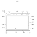
FIG. 7 illustrates a front view of a state in which a bare cell, a circuit module, and a frame are assembled in the battery pack shown inFIG. 6 ; -
FIG. 8 illustrates an exploded perspective view of a battery pack according to yet another embodiment; and -
FIG. 9 illustrates a front view of a state in which a bare cell, a circuit module, and a frame are assembled in the battery pack shown inFIG. 8 . - Example embodiments will now be described more fully hereinafter with reference to the accompanying drawings; however, they may be embodied in different forms and should not be construed as limited to the embodiments set forth herein. Rather, these embodiments are provided so that this disclosure will be thorough and complete, and will fully convey the scope of the invention to those skilled in the art. In the drawing figures, the dimensions of layers and regions may be exaggerated for clarity of illustration. It will also be understood that when a layer or element is referred to as being "on" another element, it can be directly on the other element, or intervening elements may also be present. In addition, it will also be understood that when an element is referred to as being "between" two elements, it can be the only element between the two elements, or one or more intervening elements may also be present. Like reference numerals refer to like elements throughout.
-
FIG. 1 illustrates a perspective view of a battery pack according to an embodiment. -
FIG. 2 illustrates an exploded perspective view of the battery pack shown inFIG. 1 . -
FIG. 3 illustrates an exploded perspective view of a bare cell shown inFIG. 2 . -
FIG. 4 illustrates a front view of a state in which a bare cell, a circuit module, and a frame are assembled in the battery pack shown inFIG. 2 .FIGS. 5A and 5B illustrate perspective views of a first protrusion part shown inFIG. 2 . - Referring to
FIGS. 1 through 4 , thebattery pack 1000 according to the present embodiment may include abare cell 100, acircuit module 200, aframe 300, and alabel 400. - The
bare cell 100 and thecircuit module 200 may be electrically connected to each other to form a core pack. Theframe 300 may be assembled to the core pack, followed by attaching alabel 400 to the resulting assembly, thereby completing thebattery pack 1000. - Referring first to
FIG. 3 , thebattery cell 300 included in the core pack may include anelectrode assembly 110, acan 120, acap assembly 130, and aninsulation case 140. Thebare cell 100 may further include aninsulating adhesion member 150. - The
bare cell 100 may be formed by accommodating theelectrode assembly 110 including apositive electrode plate 111, anegative electrode plate 113, and aseparator 112 in thecan 120 together with an electrolyte, and sealing an upper end opening 123 of thecan 120 by thecap assembly 130. When viewed from an external side, as shown inFIG. 2 , thebare cell 100 may include first andsecond surfaces short side surfaces long side surfaces - The
electrode assembly 110 may be formed by stacking and winding thepositive electrode plate 111, thenegative electrode plate 113, and theseparator 112 disposed therebetween. Thepositive electrode plate 111 may include apositive electrode tab 114 and thenegative electrode plate 113 may include anegative electrode tab 115. Theseparator 112 may insulate thepositive electrode plate 111 and thenegative electrode plate 113 from each other and may be formed of a porous film so as to allow an electrolyte to pass. - The
can 120, including a pair oflong side surfaces 121, a pair ofshort side surfaces 122, and abottom surface 124, may have a substantially box shape, and an upper portion of thecan 120 may be open, thus forming an upper end opening 123. Here, thelong side surfaces 121 of thecan 120 may correspond to thelong side surfaces bare cell 100, theshort side surfaces 122 of thecan 120 may correspond to thefirst surface 100a and thesecond surface 100f of thebare cell 100, and thebottom surface 124 of thecan 120 may corresponds to theshort surface 100c of thebare cell 100. The upper end opening 123 may be a portion into which theelectrode assembly 110 is inserted. The upper portion of thecan 120 may be sealed by thecap assembly 130, thereby preventing leakage of the electrolyte. Thecan 120 may be made of, e.g., a light-weight and ductile metal, such as aluminum or an aluminum alloy. In an implementation, thecan 120 may be formed by, e.g., a deep drawing process, and thelong side surfaces 121, theshort side surfaces 122, and thebottom surface 124 of thecan 120 may be integrally formed. - The
cap assembly 130 may include anelectrode terminal 131, acap plate 133, aninsulation plate 136, and aterminal plate 137. Agasket tube 132 may be inserted between thecap plate 133 and theelectrode terminal 132, and theelectrode terminal 131 and theterminal plate 137 may be electrically connected to each other. Thecap plate 133 and theelectrode terminal 131 may be short side surfaces 100b of thebare cell 100. Theinsulation plate 136 may insulate thecap plate 133 and theterminal plate 137 from each other. Anelectrolyte injection hole 134 may be formed at one side of thecap plate 133. A plug (not shown) may be provided for sealing theelectrolyte injection hole 134 once an electrolyte is injected into theelectrolyte injection hole 134. Asafety vent 135 may be formed at the other side of thecap plate 133. Thesafety vent 135 may have a thickness smaller than that of thecap plate 133. Thesafety vent 135 may be opened to release internal gases when an internal pressure of thecan 120 exceeds an operating pressure of thesafety vent 135. - The
insulation case 140 may be formed at the upper end opening 123 of thecan 120 and may insulate theelectrode assembly 110 and thecap assembly 130 from each other. Theinsulation case 140 may be made of, e.g., polypropylene, which is an insulating polymer resin. Ahole 141 for a negative electrode tab may be formed at one side of theinsulation case 140 to allow thenegative electrode tab 115 to pass and ahole 142 for a positive electrode tab may be formed at another side of theinsulation case 140 to allow thepositive electrode tab 114 to pass. Additionally, anelectrolyte passing hole 143 may be formed at a location corresponding to theelectrolyte injection hole 134 in theinsulation case 140. - The insulating
adhesion member 150 may be attached to thefirst surface 100a and oneshort side surface 100b of thebare cell 100 to prevent a short circuit between thebare cell 100 and thecircuit module 200. The insulatingadhesion member 150 may include ahole 150a at a region corresponding to theelectrode terminal 131, thus exposing theelectrode terminal 131 protruding from the oneshort side surface 100b of thebare cell 100. The insulatingadhesion member 150 may be an insulation tape having an insulating capability and may be capable of being adhered to thebare cell 100. - Referring to
FIG. 2 , thecircuit module 200 may include a printedcircuit board 210, anexternal terminal 220, acoupling protrusion 230, and leadtabs - The printed
circuit board 210 may be made of a plate-shaped resin. The printedcircuit board 210 may include circuits for controlling charging and discharging operation of a battery. In order to implement such circuits, the printedcircuit board 210 may include circuit elements (not shown). - In order to connect the
circuit module 200 to an external electronic device (not shown), theexternal terminal 220 may be installed in the printedcircuit board 210 and exposed outwardly. - The
coupling protrusion 230 may be formed at anouter side surface 210a of the printedcircuit board 210. Thecoupling protrusion 230 may facilitate physically connecting thecircuit module 200 and theframe 300 to each other and may be fixedly inserted into acoupling hole 315 in theframe 300. Thecoupling protrusion 230 may be integrally formed with the printedcircuit board 210. Such a formation may help prevent thecoupling protrusion 230 from separating from the printedcircuit board 210 in the event of, e.g., a shock generated when thecoupling protrusion 230 is inserted into thecoupling hole 315 formed in theframe 300. - The
lead tabs circuit board 210. Thelead tabs circuit board 210 to thebare cell 100. Thelead tabs first lead tab 241 connected to theelectrode terminal 131 of thebare cell 100 and asecond lead tab 242 connected to anothershort side surface 100c of thebare cell 100. In the present embodiment, theelectrode terminal 131 may function as a negative electrode and the othershort side surface 100c of thebare cell 100 may function as a positive electrode, i.e., having a polarity opposite to that of theelectrode terminal 131. Thus, thefirst lead tab 241 connected to theelectrode terminal 131 may correspond to a negative electrode terminal and thesecond lead tab 242 connected to the othershort side surface 100c may correspond to a positive electrode terminal. Of course, theelectrode terminal 131 and the othershort side surface 100c of thebare cell 100 may have opposite polarities. - The
first lead tab 241 and thesecond lead tab 242 may be bent in a substantially 'L' shape. One side of thefirst lead tab 241 may be connected to theelectrode terminal 131 and insulated from the oneshort side surface 100b of thebare cell 100. Another side of thefirst lead tab 241 may be connected to a connection terminal in the printedcircuit board 210 and insulated from thefirst surface 100a of thebare cell 100. One side of thesecond lead tab 242 may connected to the othershort side surface 100c of thebare cell 100. Another side of thesecond lead tab 242 may be connected to another connection terminal in the printedcircuit board 210 and insulated from thefirst surface 100a of thebare cell 100. Thefirst lead tab 241 and thesecond lead tab 242 may be made of a conductive material, e.g., nickel or a nickel alloy, to facilitate formation of an electrical connection between thebare cell 100 and thecircuit module 200. - The
frame 300 may include a front surface, or portion, 310, a pair of side surfaces, or arms, 320 and 330 extending at opposite ends of the front portion, and extendingsurfaces 340, which may form a lip for retaining the battery. Theframe 300 may be formed as an all-in-one type or single piece, i.e., one piece, using, e.g., injection molding, to cover thefirst surface 100a and the pair of short side surfaces 100b and 100c of thebare cell 100 on which thecircuit module 200 is disposed. Theframe 300 may be assembled to thecircuit module 200 connected to thebare cell 100. Here, thecircuit module 200 and theframe 300 may be physically connected by thecoupling protrusion 230 in thecircuit module 200 and thecoupling hole 315 in theframe 300. - The
front surface 310 may have a size corresponding to a size of thefirst surface 100a of thebare cell 100 on which thecircuit module 200 is disposed. Thefront surface 310 may cover thefirst surface 100a of thebare cell 100 when thefront surface 310 is coupled to thecircuit module 200. Thefront surface 310 may include anopening 313 at a location corresponding to theexternal terminal 220 of thecircuit module 200 and thus may expose theexternal terminal 220. - A
locker 311 extending through thefront surface 310 and the extendingsurface 340 may be formed at one side of thefront surface 310. Ahook 312 extending through thefront surface 310 and the extendingsurface 340 may be formed at another side of thefront surface 310. Thelocker 311 and thehook 312 may be provided to facilitate insertion of thebattery pack 1000 into an external device in a proper direction. - The pair of side surfaces 320 and 330 may be connected to the
front surface 310 and may have sizes corresponding to sizes of the pair of short side surfaces 100b and 100c of thebare cell 100. The pair of side surfaces 320 and 330 may cover the pair ofshort side surface bare cell 100 when they are coupled to thecircuit module 200. The side surfaces 320 and 330 may include afirst side surface 320 connected to oneshort side surface 100b of thebare cell 100 and asecond side surface 330 connected to the othershort side surface 100c of thebare cell 100. - A
handle 320a of an engraved, or recessed, type may be formed at an exterior bottom of thefirst side surface 320 and may facilitate an easy disconnection of thebattery pack 1000 from the external device. Afirst protrusion part 321 may be formed in an interior bottom of thefirst side surface 320. Thefirst protrusion part 321 may be coupled to the oneshort side surface 100b of thebare cell 100. In addition, thefirst protrusion part 321 may be coupled to a portion of the oneshort side surface 100b where thesafety vent 135 is formed. - Referring to
FIG. 4 , a thickness d1 of thefirst protrusion part 321 may be about the same as a sum of thicknesses of theelectrode terminal 131 of thebare cell 100 and a thickness of thefirst lead tab 241, thereby eliminating a gap between thebare cell 100 and theframe 300. - A
second protrusion part 331 may be formed in an interior bottom of thesecond side surface 330. Thesecond protrusion part 331 may be coupled to the othershort side surface 100c of thebare cell 100. A thickness d2 of thesecond protrusion part 331 may be the same as a thickness of thesecond lead tab 242, thereby eliminating a gap between thebare cell 100 and theframe 300. In an implementation, the thickness d1 of thefirst protrusion part 321 may be greater than the thickness d2 of thesecond protrusion part 331, e.g., d1 > d2. - In other words, the
first protrusion part 321 and thesecond protrusion part 331 may facilitate tight coupling of theframe 300 and thebare cell 100 to each other without a gap therebetween, thereby increasing a coupling force between theframe 300 and thebare cell 100. - Referring to
FIGS. 5A and 5B , a gas exhaust path may be formed in thefirst protrusion part 321. The gas exhaust path may include a hole or a groove to release gases generated in thebare cell 100. - As shown in
FIG. 5A , thefirst protrusion part 321 may have agas release hole 321a formed therein. Thegas release hole 321a may pass through thefirst protrusion part 321. In particular, thegas release hole 321a may be formed at a location corresponding to thesafety vent 135 in thebare cell 100. Thegas release hole 321a a may exhaust gas released through thesafety vent 135 to the outside. In addition, thefirst side surface 320 may have a through-hole (not shown) at a location corresponding to thegas release hole 321a. As illustrated inFIG. 5A , thegas release hole 321a may have a circular shape, but the embodiments are not limited thereto. For example, thegas release hole 321a may have a triangular shape, a rectangular shape, or other polygonal shapes. - As illustrated in
FIG. 5B , thefirst protrusion part 321 may also include a gas exhaust groove 321b. The gas exhaust groove 321b may form a gas exhaust path; and a portion of the gas exhaust groove 321b may correspond to thesafety vent 135 formed in thebare cell 100. Thus, gas released through thesafety vent 135 may be exhausted to the outside through the gas exhaust groove 321b. - The extending
surface 340 may extend from edges of thefront surface 310 and the pair of side surfaces 320 and 330 toward the pair oflong side surface bare cell 100. The extendingsurface 340 may cover portions of the pair oflong side surface bare cell 100 when thebare cell 100 is coupled to thecircuit module 200 connected thereto. Thecoupling hole 315 may be formed in the extendingsurface 340; and thecoupling protrusion 230 in thecircuit module 200 may be inserted into thecoupling hole 315. Thecoupling hole 315 may have a size the same as or slightly smaller than thecoupling protrusion 230 to facilitate prevention of thecoupling protrusion 230 in thecircuit module 200 from being readily disengaged from thecoupling hole 315 once thecoupling protrusion 230 is inserted into thecoupling hole 315. - After the
circuit module 200 connected to thebare cell 100 is covered by theframe 300, thelabel 400 may be adhered so as to cover the pair oflong side surface second surface 100f of thebare cell 100. In such a manner, thelabel 400 may increase a coupling force between thebare cell 100, thecircuit module 200, and theframe 300, while protecting the completedbattery pack 1000 from external shocks. - As described above, since the
battery pack 1000 according to the present embodiment may include theframe 300 having theprotrusion parts frame 300 and a core pack including thebare cell 100 and thecircuit module 200 connected to each other may be increased. - A battery pack according to another embodiment will now be described.
-
FIG. 6 illustrates an exploded perspective view of a battery pack according to another embodiment.FIG. 7 illustrates a front view of a state in which a bare cell, a circuit module, and a frame are assembled in the battery pack shown inFIG. 6 . - The battery pack according to the present embodiment is substantially the same as the battery pack shown in
FIGS. 2 and4 , and only differences therebetween will be described herein. - Referring to
FIGS. 6 and7 , thebattery pack 2000 according to the present embodiment may include abare cell 100, acircuit module 200, aframe 1300, and alabel 400. - The
frame 1300 may include afront surface 310, a pair of side surfaces 320 and 330, extendingsurfaces 340, and arear surface 350. Theframe 1300 may be formed in an all-in-one type or single piece using, e.g., injection molding, to cover thefirst surface 100a, the pair ofshort side surface second surface 100f of thebare cell 100 including thecircuit module 200 coupled thereto. Theframe 1300 may be assembled to thecircuit module 200 connected to thebare cell 100. - The extending
surfaces 340 may extend from edges of thefront surface 310, the pair of side surfaces 320 and 330, and therear surface 350 to the pair oflong side surfaces bare cell 100. The extendingsurfaces 340 may cover portions of the pair oflong side surface bare cell 100 when thebare cell 100 is coupled to thecircuit module 200 connected thereto. - The
rear surface 350 may be connected to the pair of side surfaces 320 and 330 and may have a size corresponding to a size of thesecond surface 100f of thebare cell 100 and may cover thesecond surface 100f of thebare cell 100 when thebare cell 100 is coupled to thecircuit module 200 connected thereto. - A battery pack according to yet another embodiment will now be described.
-
FIG. 8 illustrates an exploded perspective view of a battery pack according to yet another embodiment.FIG. 9 illustrates a front view of a state in which a bare cell, a circuit module, and a frame are assembled in the battery pack shown inFIG. 8 . - The battery pack according to the present embodiment is substantially the same as the battery pack shown in
FIGS. 2 and4 , and only differences therebetween will be described herein. - Referring to
FIGS. 8 and9 , thebattery pack 3000 according to the present embodiment may include abare cell 100, acircuit module 200, aframe 2300, and alabel 400. - The
frame 2300 may include afront surface 310, aside surface 320, and an extendingsurface 340. In addition, theframe 2300 may include a separate additional side surface, or arm, 360. Theframe 2300 may cover thefirst surface 100a and a pair of short side surfaces 100b and 100c of thebare cell 100 in which thecircuit module 200 is disposed. Theframe 2300 may be formed in an all-in-one type in which thefront surface 310, theside surface 320, and the extendingsurface 340 are integrally formed; and theadditional side surface 360 may be coupled to theframe 2300. - The
additional side surface 360 may have a shape corresponding to a shape of theside surface 320 of the previous embodiment and may cover the othershort side surface 100c of thebare cell 100. An additional extendingsurface 370 may extend from theadditional side surface 360 coupled to the extendingsurface 340 to the pair oflong side surface bare cell 100. The additional extendingsurface 370 may cover portions of pair oflong side surface bare cell 100. - In addition, a
third protrusion part 361 may be formed in an interior bottom of theadditional side surface 360. Thethird protrusion part 361 may be coupled to the othershort side surface 100c of thebare cell 100. Thethird protrusion part 361 may have a thickness d3 that is about the same as a thickness of thesecond lead tab 242, thereby eliminating a gap between thebare cell 100 and theframe 2300. In an implementation, the thickness d3 of thethird protrusion part 361 may be smaller than a thickness d1 of thefirst protrusion part 331, e.g., d3 < d1. - According to the embodiments, when the frame and a core pack including a bare cell and a protection circuit module are coupled to each other, an undesirable gap between the frame and the core pack may be prevented.
- The embodiments provide a battery pack capable of increasing a coupling force between a core pack and a frame, the core pack including of a bare cell and a circuit module.
- Exemplary embodiments of a battery pack have been disclosed herein, and although specific terms are employed, they are used and are to be interpreted in a generic and descriptive sense only and not for purpose of limitation. Accordingly, it will be understood by those of ordinary skill in the art that various changes in form and details may be made without departing from the scope of the present invention as set forth in the following claims.
Claims (15)
- A battery pack, comprising:a bare cell (100);a circuit module (200) on a first surface (100a) of the bare cell, the circuit module being electrically connected to the bare cell; anda frame (300, 1300, 2300) covering a portion of the bare cell including the circuit module,wherein the frame has a protrusion part (321, 331, 361) at an interior portion of an arm thereof, the protrusion part being coupled to an end surface (100b, 100c) of the bare cell.
- The battery pack as claimed in claim 1, wherein the frame includes:a front portion (310) corresponding to the first surface (100a) of the bare cell;a pair of arms (320, 330) corresponding to the end surfaces of the bare cell; andextending surfaces (340) extending from edges of the front portion and the pair of arms to planar surfaces of the bare cell,wherein the frame is an all-in-one type in which the front portion, the arms and the extending surfaces are integrally formed.
- The battery pack as claimed in claim 2, wherein the frame covers the first surface (100a) and the end surfaces (100b, 100c) of the bare cell.
- The battery pack as claimed in claim 2 or 3, wherein the arms of the frame include:a first arm (320) corresponding to one end surface of the bare cell, the first arm including a first protrusion part (321) at an end of the first arm distal from the front portion; anda second arm corresponding to another end surface of the bare cell, the second arm including a second protrusion part (331) at an end of the second arm distal from the front portion.
- The battery pack as claimed in claim 4, wherein the first protrusion part has a gas release hole or a gas exhaust groove therein.
- The battery pack as claimed in claim 4 or 5, wherein a thickness of the first protrusion part is greater than a thickness of the second protrusion part.
- The battery pack as claimed in any one of claims 2 to 6, wherein the frame further includes a rear portion (350) corresponding to a second surface (100f) of the bare cell opposite the first surface (100a); and
extending surfaces extending from edges of the rear portion to planar surfaces of the bare cell,
wherein the rear portion is integrally formed with the frame. - The battery pack as claimed in claim 7, wherein the frame covers the first surface, the pair of end surfaces, and the second surface of the bare cell.
- The battery pack as claimed in claim 1, wherein the frame (2300) includes:a front portion (310) corresponding to the first surface of the bare cell;an arm (320) corresponding to one of the pair of end surfaces of the bare cell;extending surfaces (340) extending from edges of the front portion and the arm to planar surfaces of the bare cell,wherein the frame is an all-in-one type in which the front surface, the arm, and the extending surfaces are integrally formed.
- The battery pack as claimed in claim 9, wherein the frame covers the first surface and the one end surface of the bare cell.
- The battery pack as claimed in claim 9 or 10, further comprising an additional arm (360) corresponding to another end surface of the bare cell, the additional arm being coupled to the frame.
- The battery pack as claimed in claim 11, wherein the additional arm includes an additional protrusion part at an interior bottom part thereof.
- The battery pack as claimed in claim 11 or 12, wherein the additional arm includes an additional extending surface thereon towards the pair of planar surfaces of the bare cell.
- The battery pack as claimed in any one of the preceding claims, wherein the circuit module includes:a printed circuit board having a plate shape;an external terminal in the printed circuit board, the external terminal being outwardly exposed; anda lead tab electrically connected to an electrode terminal of the bare cell, wherein the lead tab may include:a first lead tab electrically connected to the electrode terminal of the bare cell; anda second lead tab electrically connected to one of the end surfaces of the bare cell.
- The battery pack as claimed in any one of the preceding claims, further comprising an insulating adhesion member attached to the first surface and one of the end surfaces of the bare cell, the insulating adhesion member being configured to prevent a short circuit between the bare cell and the circuit module and/or further comprising a label attached to a pair of planar surfaces and the second surface of the bare cell.
Applications Claiming Priority (1)
| Application Number | Priority Date | Filing Date | Title |
|---|---|---|---|
| KR1020100053720A KR101222397B1 (en) | 2010-06-08 | 2010-06-08 | Battery pack |
Publications (2)
| Publication Number | Publication Date |
|---|---|
| EP2395575A1 true EP2395575A1 (en) | 2011-12-14 |
| EP2395575B1 EP2395575B1 (en) | 2013-07-03 |
Family
ID=44722186
Family Applications (1)
| Application Number | Title | Priority Date | Filing Date |
|---|---|---|---|
| EP11156215.3A Active EP2395575B1 (en) | 2010-06-08 | 2011-02-28 | Battery pack |
Country Status (5)
| Country | Link |
|---|---|
| US (1) | US9112190B2 (en) |
| EP (1) | EP2395575B1 (en) |
| JP (1) | JP5413746B2 (en) |
| KR (1) | KR101222397B1 (en) |
| CN (1) | CN102280601B (en) |
Families Citing this family (9)
| Publication number | Priority date | Publication date | Assignee | Title |
|---|---|---|---|---|
| EP2827401B1 (en) * | 2012-03-16 | 2017-09-27 | NEC Corporation | Battery housing and power-storage device |
| KR101908452B1 (en) * | 2012-06-28 | 2018-10-17 | 에스케이이노베이션 주식회사 | Easy assembling all-in-one secondary battery module |
| KR101675622B1 (en) * | 2013-04-22 | 2016-11-11 | 삼성에스디아이 주식회사 | Secondary Battery having corrosion protective structure |
| KR101619926B1 (en) * | 2013-09-27 | 2016-05-12 | 주식회사 엘지화학 | Battery Pack Having PCM Case |
| CN105573214A (en) * | 2016-01-18 | 2016-05-11 | 江苏工程职业技术学院 | Control method and charging method for multifunctional charger baby |
| KR102152069B1 (en) * | 2016-03-31 | 2020-09-04 | 가부시키가이샤 도요다 지도숏키 | Power storage device |
| JP2018110968A (en) * | 2018-04-23 | 2018-07-19 | 株式会社三洋物産 | Game machine |
| KR102470111B1 (en) | 2019-11-06 | 2022-11-23 | 대구대학교 산학협력단 | Treatment method of emergency patient during transforting by vehicle |
| CN114094244A (en) * | 2021-11-22 | 2022-02-25 | 东莞新能安科技有限公司 | Battery pack and electric equipment |
Citations (3)
| Publication number | Priority date | Publication date | Assignee | Title |
|---|---|---|---|---|
| US20030008208A1 (en) * | 2001-06-19 | 2003-01-09 | Masato Yamazaki | Battery |
| EP1919009A2 (en) * | 2006-10-24 | 2008-05-07 | Samsung SDI Co., Ltd. | Lithium Rechargeable Battery |
| US20080261087A1 (en) * | 2007-04-19 | 2008-10-23 | Youngcheol Jang | Pack type battery |
Family Cites Families (13)
| Publication number | Priority date | Publication date | Assignee | Title |
|---|---|---|---|---|
| US4194061A (en) * | 1979-03-23 | 1980-03-18 | Polaroid Corporation | Compact high voltage battery |
| JP4707923B2 (en) * | 2002-06-17 | 2011-06-22 | パナソニック株式会社 | Assembled battery |
| WO2005078825A1 (en) | 2004-02-13 | 2005-08-25 | Lg Chem, Ltd. | Battery pack of improved structure |
| JP4744127B2 (en) * | 2004-12-02 | 2011-08-10 | 三洋電機株式会社 | Battery pack |
| KR100686814B1 (en) * | 2005-04-26 | 2007-02-26 | 삼성에스디아이 주식회사 | Polymer battery pack and manufacturing method the same |
| JP4902156B2 (en) * | 2005-09-02 | 2012-03-21 | 三洋電機株式会社 | Battery pack |
| JP2007220321A (en) * | 2006-02-14 | 2007-08-30 | Matsushita Electric Ind Co Ltd | Lithium secondary cell |
| KR100778993B1 (en) * | 2006-08-31 | 2007-11-22 | 삼성에스디아이 주식회사 | Rechargeable battery including resin vessel type side cover |
| KR100833736B1 (en) * | 2006-10-24 | 2008-05-29 | 삼성에스디아이 주식회사 | Battery Pack |
| JP5080073B2 (en) | 2006-12-12 | 2012-11-21 | 三洋電機株式会社 | Battery pack |
| KR100835743B1 (en) | 2007-05-01 | 2008-06-05 | (주)이젠솔루션 | A battery pack for secondary battery |
| KR100922468B1 (en) * | 2007-09-21 | 2009-10-21 | 삼성에스디아이 주식회사 | Battery pack |
| KR100876266B1 (en) | 2007-09-28 | 2008-12-26 | 삼성에스디아이 주식회사 | Rechargeable battery |
-
2010
- 2010-06-08 KR KR1020100053720A patent/KR101222397B1/en active IP Right Grant
- 2010-11-19 JP JP2010258853A patent/JP5413746B2/en active Active
-
2011
- 2011-01-06 US US12/929,189 patent/US9112190B2/en active Active
- 2011-01-07 CN CN201110006016.XA patent/CN102280601B/en active Active
- 2011-02-28 EP EP11156215.3A patent/EP2395575B1/en active Active
Patent Citations (3)
| Publication number | Priority date | Publication date | Assignee | Title |
|---|---|---|---|---|
| US20030008208A1 (en) * | 2001-06-19 | 2003-01-09 | Masato Yamazaki | Battery |
| EP1919009A2 (en) * | 2006-10-24 | 2008-05-07 | Samsung SDI Co., Ltd. | Lithium Rechargeable Battery |
| US20080261087A1 (en) * | 2007-04-19 | 2008-10-23 | Youngcheol Jang | Pack type battery |
Also Published As
| Publication number | Publication date |
|---|---|
| KR101222397B1 (en) | 2013-01-16 |
| US20110300412A1 (en) | 2011-12-08 |
| EP2395575B1 (en) | 2013-07-03 |
| JP2011258540A (en) | 2011-12-22 |
| US9112190B2 (en) | 2015-08-18 |
| KR20110133990A (en) | 2011-12-14 |
| CN102280601B (en) | 2014-10-08 |
| JP5413746B2 (en) | 2014-02-12 |
| CN102280601A (en) | 2011-12-14 |
Similar Documents
| Publication | Publication Date | Title |
|---|---|---|
| EP2395575B1 (en) | Battery pack | |
| US7887948B2 (en) | Pack type battery | |
| JP5059731B2 (en) | Battery pack | |
| US7618737B2 (en) | Lithium secondary battery and method for manufacturing the same | |
| EP1995804B1 (en) | Battery pack | |
| EP2073295A2 (en) | Protective circuit board for a battery | |
| US20070202364A1 (en) | Secondary battery | |
| US20060269835A1 (en) | Jelly-roll type electrode assembly and lithium secondary battery with the same | |
| WO2011078241A1 (en) | Battery module and assembled battery | |
| KR102168675B1 (en) | Pouch Type Secondary Battery Pack Having Protection Circuit Module | |
| EP2043177B1 (en) | Protective circuit board and battery pack using the same | |
| US20140030564A1 (en) | Rechargeable battery | |
| US20160276647A1 (en) | Battery pack | |
| KR20090042535A (en) | Battery pack | |
| KR20130065287A (en) | Battery pack | |
| KR20130135063A (en) | Rechargeable battery pack | |
| KR101776897B1 (en) | Pouch type secondary battery and method for manufacturing the same | |
| US8465870B2 (en) | Secondary battery with improved capacity and installation convenience | |
| KR102221780B1 (en) | Battery pack and method for manufcturing the same | |
| KR20160103255A (en) | Battery Pack Having Small PCM | |
| US20140004388A1 (en) | Battery pack and case | |
| KR101264432B1 (en) | Battery Pack Including Out-Case With A Step | |
| KR101386168B1 (en) | Rechargeable battery pack | |
| KR20080024859A (en) | Battery pack | |
| US8765299B2 (en) | Electrode assembly and secondary battery including the same |
Legal Events
| Date | Code | Title | Description |
|---|---|---|---|
| AK | Designated contracting states |
Kind code of ref document: A1 Designated state(s): AL AT BE BG CH CY CZ DE DK EE ES FI FR GB GR HR HU IE IS IT LI LT LU LV MC MK MT NL NO PL PT RO RS SE SI SK SM TR |
|
| AX | Request for extension of the european patent |
Extension state: BA ME |
|
| PUAI | Public reference made under article 153(3) epc to a published international application that has entered the european phase |
Free format text: ORIGINAL CODE: 0009012 |
|
| 17P | Request for examination filed |
Effective date: 20120321 |
|
| RIC1 | Information provided on ipc code assigned before grant |
Ipc: H01M 2/34 20060101ALI20120831BHEP Ipc: H01M 2/04 20060101ALI20120831BHEP Ipc: H01M 2/10 20060101ALI20120831BHEP Ipc: H01M 10/42 20060101ALI20120831BHEP Ipc: H01M 2/02 20060101AFI20120831BHEP |
|
| GRAP | Despatch of communication of intention to grant a patent |
Free format text: ORIGINAL CODE: EPIDOSNIGR1 |
|
| GRAS | Grant fee paid |
Free format text: ORIGINAL CODE: EPIDOSNIGR3 |
|
| GRAA | (expected) grant |
Free format text: ORIGINAL CODE: 0009210 |
|
| AK | Designated contracting states |
Kind code of ref document: B1 Designated state(s): AL AT BE BG CH CY CZ DE DK EE ES FI FR GB GR HR HU IE IS IT LI LT LU LV MC MK MT NL NO PL PT RO RS SE SI SK SM TR |
|
| REG | Reference to a national code |
Ref country code: GB Ref legal event code: FG4D |
|
| REG | Reference to a national code |
Ref country code: CH Ref legal event code: EP Ref country code: AT Ref legal event code: REF Ref document number: 620202 Country of ref document: AT Kind code of ref document: T Effective date: 20130715 |
|
| REG | Reference to a national code |
Ref country code: IE Ref legal event code: FG4D |
|
| REG | Reference to a national code |
Ref country code: DE Ref legal event code: R096 Ref document number: 602011002171 Country of ref document: DE Effective date: 20130829 |
|
| PG25 | Lapsed in a contracting state [announced via postgrant information from national office to epo] |
Ref country code: SI Free format text: LAPSE BECAUSE OF FAILURE TO SUBMIT A TRANSLATION OF THE DESCRIPTION OR TO PAY THE FEE WITHIN THE PRESCRIBED TIME-LIMIT Effective date: 20130703 |
|
| REG | Reference to a national code |
Ref country code: AT Ref legal event code: MK05 Ref document number: 620202 Country of ref document: AT Kind code of ref document: T Effective date: 20130703 |
|
| REG | Reference to a national code |
Ref country code: NL Ref legal event code: VDEP Effective date: 20130703 |
|
| REG | Reference to a national code |
Ref country code: LT Ref legal event code: MG4D |
|
| PG25 | Lapsed in a contracting state [announced via postgrant information from national office to epo] |
Ref country code: NO Free format text: LAPSE BECAUSE OF FAILURE TO SUBMIT A TRANSLATION OF THE DESCRIPTION OR TO PAY THE FEE WITHIN THE PRESCRIBED TIME-LIMIT Effective date: 20131003 Ref country code: LT Free format text: LAPSE BECAUSE OF FAILURE TO SUBMIT A TRANSLATION OF THE DESCRIPTION OR TO PAY THE FEE WITHIN THE PRESCRIBED TIME-LIMIT Effective date: 20130703 Ref country code: PT Free format text: LAPSE BECAUSE OF FAILURE TO SUBMIT A TRANSLATION OF THE DESCRIPTION OR TO PAY THE FEE WITHIN THE PRESCRIBED TIME-LIMIT Effective date: 20131104 Ref country code: CY Free format text: LAPSE BECAUSE OF FAILURE TO SUBMIT A TRANSLATION OF THE DESCRIPTION OR TO PAY THE FEE WITHIN THE PRESCRIBED TIME-LIMIT Effective date: 20130731 Ref country code: BE Free format text: LAPSE BECAUSE OF FAILURE TO SUBMIT A TRANSLATION OF THE DESCRIPTION OR TO PAY THE FEE WITHIN THE PRESCRIBED TIME-LIMIT Effective date: 20130703 Ref country code: HR Free format text: LAPSE BECAUSE OF FAILURE TO SUBMIT A TRANSLATION OF THE DESCRIPTION OR TO PAY THE FEE WITHIN THE PRESCRIBED TIME-LIMIT Effective date: 20130703 Ref country code: AT Free format text: LAPSE BECAUSE OF FAILURE TO SUBMIT A TRANSLATION OF THE DESCRIPTION OR TO PAY THE FEE WITHIN THE PRESCRIBED TIME-LIMIT Effective date: 20130703 Ref country code: SE Free format text: LAPSE BECAUSE OF FAILURE TO SUBMIT A TRANSLATION OF THE DESCRIPTION OR TO PAY THE FEE WITHIN THE PRESCRIBED TIME-LIMIT Effective date: 20130703 Ref country code: IS Free format text: LAPSE BECAUSE OF FAILURE TO SUBMIT A TRANSLATION OF THE DESCRIPTION OR TO PAY THE FEE WITHIN THE PRESCRIBED TIME-LIMIT Effective date: 20131103 |
|
| PG25 | Lapsed in a contracting state [announced via postgrant information from national office to epo] |
Ref country code: NL Free format text: LAPSE BECAUSE OF FAILURE TO SUBMIT A TRANSLATION OF THE DESCRIPTION OR TO PAY THE FEE WITHIN THE PRESCRIBED TIME-LIMIT Effective date: 20130703 Ref country code: PL Free format text: LAPSE BECAUSE OF FAILURE TO SUBMIT A TRANSLATION OF THE DESCRIPTION OR TO PAY THE FEE WITHIN THE PRESCRIBED TIME-LIMIT Effective date: 20130703 Ref country code: ES Free format text: LAPSE BECAUSE OF FAILURE TO SUBMIT A TRANSLATION OF THE DESCRIPTION OR TO PAY THE FEE WITHIN THE PRESCRIBED TIME-LIMIT Effective date: 20131014 Ref country code: FI Free format text: LAPSE BECAUSE OF FAILURE TO SUBMIT A TRANSLATION OF THE DESCRIPTION OR TO PAY THE FEE WITHIN THE PRESCRIBED TIME-LIMIT Effective date: 20130703 Ref country code: LV Free format text: LAPSE BECAUSE OF FAILURE TO SUBMIT A TRANSLATION OF THE DESCRIPTION OR TO PAY THE FEE WITHIN THE PRESCRIBED TIME-LIMIT Effective date: 20130703 Ref country code: GR Free format text: LAPSE BECAUSE OF FAILURE TO SUBMIT A TRANSLATION OF THE DESCRIPTION OR TO PAY THE FEE WITHIN THE PRESCRIBED TIME-LIMIT Effective date: 20131004 |
|
| PG25 | Lapsed in a contracting state [announced via postgrant information from national office to epo] |
Ref country code: CY Free format text: LAPSE BECAUSE OF FAILURE TO SUBMIT A TRANSLATION OF THE DESCRIPTION OR TO PAY THE FEE WITHIN THE PRESCRIBED TIME-LIMIT Effective date: 20130703 |
|
| PG25 | Lapsed in a contracting state [announced via postgrant information from national office to epo] |
Ref country code: RO Free format text: LAPSE BECAUSE OF FAILURE TO SUBMIT A TRANSLATION OF THE DESCRIPTION OR TO PAY THE FEE WITHIN THE PRESCRIBED TIME-LIMIT Effective date: 20130703 Ref country code: SK Free format text: LAPSE BECAUSE OF FAILURE TO SUBMIT A TRANSLATION OF THE DESCRIPTION OR TO PAY THE FEE WITHIN THE PRESCRIBED TIME-LIMIT Effective date: 20130703 Ref country code: EE Free format text: LAPSE BECAUSE OF FAILURE TO SUBMIT A TRANSLATION OF THE DESCRIPTION OR TO PAY THE FEE WITHIN THE PRESCRIBED TIME-LIMIT Effective date: 20130703 Ref country code: DK Free format text: LAPSE BECAUSE OF FAILURE TO SUBMIT A TRANSLATION OF THE DESCRIPTION OR TO PAY THE FEE WITHIN THE PRESCRIBED TIME-LIMIT Effective date: 20130703 Ref country code: CZ Free format text: LAPSE BECAUSE OF FAILURE TO SUBMIT A TRANSLATION OF THE DESCRIPTION OR TO PAY THE FEE WITHIN THE PRESCRIBED TIME-LIMIT Effective date: 20130703 |
|
| PLBE | No opposition filed within time limit |
Free format text: ORIGINAL CODE: 0009261 |
|
| STAA | Information on the status of an ep patent application or granted ep patent |
Free format text: STATUS: NO OPPOSITION FILED WITHIN TIME LIMIT |
|
| PG25 | Lapsed in a contracting state [announced via postgrant information from national office to epo] |
Ref country code: IT Free format text: LAPSE BECAUSE OF FAILURE TO SUBMIT A TRANSLATION OF THE DESCRIPTION OR TO PAY THE FEE WITHIN THE PRESCRIBED TIME-LIMIT Effective date: 20130703 |
|
| 26N | No opposition filed |
Effective date: 20140404 |
|
| REG | Reference to a national code |
Ref country code: DE Ref legal event code: R097 Ref document number: 602011002171 Country of ref document: DE Effective date: 20140404 |
|
| PG25 | Lapsed in a contracting state [announced via postgrant information from national office to epo] |
Ref country code: LU Free format text: LAPSE BECAUSE OF FAILURE TO SUBMIT A TRANSLATION OF THE DESCRIPTION OR TO PAY THE FEE WITHIN THE PRESCRIBED TIME-LIMIT Effective date: 20140228 Ref country code: MC Free format text: LAPSE BECAUSE OF FAILURE TO SUBMIT A TRANSLATION OF THE DESCRIPTION OR TO PAY THE FEE WITHIN THE PRESCRIBED TIME-LIMIT Effective date: 20130703 |
|
| REG | Reference to a national code |
Ref country code: CH Ref legal event code: PL |
|
| PG25 | Lapsed in a contracting state [announced via postgrant information from national office to epo] |
Ref country code: LI Free format text: LAPSE BECAUSE OF NON-PAYMENT OF DUE FEES Effective date: 20140228 Ref country code: CH Free format text: LAPSE BECAUSE OF NON-PAYMENT OF DUE FEES Effective date: 20140228 |
|
| REG | Reference to a national code |
Ref country code: IE Ref legal event code: MM4A |
|
| PG25 | Lapsed in a contracting state [announced via postgrant information from national office to epo] |
Ref country code: IE Free format text: LAPSE BECAUSE OF NON-PAYMENT OF DUE FEES Effective date: 20140228 |
|
| REG | Reference to a national code |
Ref country code: FR Ref legal event code: PLFP Year of fee payment: 6 |
|
| PG25 | Lapsed in a contracting state [announced via postgrant information from national office to epo] |
Ref country code: MT Free format text: LAPSE BECAUSE OF FAILURE TO SUBMIT A TRANSLATION OF THE DESCRIPTION OR TO PAY THE FEE WITHIN THE PRESCRIBED TIME-LIMIT Effective date: 20130703 |
|
| PG25 | Lapsed in a contracting state [announced via postgrant information from national office to epo] |
Ref country code: SM Free format text: LAPSE BECAUSE OF FAILURE TO SUBMIT A TRANSLATION OF THE DESCRIPTION OR TO PAY THE FEE WITHIN THE PRESCRIBED TIME-LIMIT Effective date: 20130703 |
|
| PG25 | Lapsed in a contracting state [announced via postgrant information from national office to epo] |
Ref country code: BG Free format text: LAPSE BECAUSE OF FAILURE TO SUBMIT A TRANSLATION OF THE DESCRIPTION OR TO PAY THE FEE WITHIN THE PRESCRIBED TIME-LIMIT Effective date: 20130703 Ref country code: RS Free format text: LAPSE BECAUSE OF FAILURE TO SUBMIT A TRANSLATION OF THE DESCRIPTION OR TO PAY THE FEE WITHIN THE PRESCRIBED TIME-LIMIT Effective date: 20130703 |
|
| PG25 | Lapsed in a contracting state [announced via postgrant information from national office to epo] |
Ref country code: HU Free format text: LAPSE BECAUSE OF FAILURE TO SUBMIT A TRANSLATION OF THE DESCRIPTION OR TO PAY THE FEE WITHIN THE PRESCRIBED TIME-LIMIT; INVALID AB INITIO Effective date: 20110228 Ref country code: TR Free format text: LAPSE BECAUSE OF FAILURE TO SUBMIT A TRANSLATION OF THE DESCRIPTION OR TO PAY THE FEE WITHIN THE PRESCRIBED TIME-LIMIT Effective date: 20130703 |
|
| REG | Reference to a national code |
Ref country code: FR Ref legal event code: PLFP Year of fee payment: 7 |
|
| REG | Reference to a national code |
Ref country code: FR Ref legal event code: PLFP Year of fee payment: 8 |
|
| PG25 | Lapsed in a contracting state [announced via postgrant information from national office to epo] |
Ref country code: MK Free format text: LAPSE BECAUSE OF FAILURE TO SUBMIT A TRANSLATION OF THE DESCRIPTION OR TO PAY THE FEE WITHIN THE PRESCRIBED TIME-LIMIT Effective date: 20130703 |
|
| PG25 | Lapsed in a contracting state [announced via postgrant information from national office to epo] |
Ref country code: AL Free format text: LAPSE BECAUSE OF FAILURE TO SUBMIT A TRANSLATION OF THE DESCRIPTION OR TO PAY THE FEE WITHIN THE PRESCRIBED TIME-LIMIT Effective date: 20130703 |
|
| REG | Reference to a national code |
Ref country code: DE Ref legal event code: R079 Ref document number: 602011002171 Country of ref document: DE Free format text: PREVIOUS MAIN CLASS: H01M0002020000 Ipc: H01M0050100000 |
|
| PGFP | Annual fee paid to national office [announced via postgrant information from national office to epo] |
Ref country code: FR Payment date: 20230208 Year of fee payment: 13 |
|
| PGFP | Annual fee paid to national office [announced via postgrant information from national office to epo] |
Ref country code: GB Payment date: 20230126 Year of fee payment: 13 Ref country code: DE Payment date: 20230131 Year of fee payment: 13 |
|
| P01 | Opt-out of the competence of the unified patent court (upc) registered |
Effective date: 20230528 |