EP2395253A2 - Hollow body element and assembled component - Google Patents
Hollow body element and assembled component Download PDFInfo
- Publication number
- EP2395253A2 EP2395253A2 EP11007027A EP11007027A EP2395253A2 EP 2395253 A2 EP2395253 A2 EP 2395253A2 EP 11007027 A EP11007027 A EP 11007027A EP 11007027 A EP11007027 A EP 11007027A EP 2395253 A2 EP2395253 A2 EP 2395253A2
- Authority
- EP
- European Patent Office
- Prior art keywords
- hollow body
- body element
- annular recess
- broad side
- sheet metal
- Prior art date
- Legal status (The legal status is an assumption and is not a legal conclusion. Google has not performed a legal analysis and makes no representation as to the accuracy of the status listed.)
- Withdrawn
Links
- 238000004080 punching Methods 0.000 claims abstract description 44
- 229910052751 metal Inorganic materials 0.000 claims abstract description 43
- 239000002184 metal Substances 0.000 claims abstract description 43
- 239000000463 material Substances 0.000 claims description 13
- 230000007704 transition Effects 0.000 claims description 8
- IHQKEDIOMGYHEB-UHFFFAOYSA-M sodium dimethylarsinate Chemical class [Na+].C[As](C)([O-])=O IHQKEDIOMGYHEB-UHFFFAOYSA-M 0.000 claims description 3
- 238000000034 method Methods 0.000 abstract description 36
- 238000004519 manufacturing process Methods 0.000 abstract description 19
- 238000005520 cutting process Methods 0.000 abstract description 14
- 230000000750 progressive effect Effects 0.000 description 26
- 230000008569 process Effects 0.000 description 17
- 239000002131 composite material Substances 0.000 description 11
- 230000015572 biosynthetic process Effects 0.000 description 6
- 238000000926 separation method Methods 0.000 description 5
- 230000000295 complement effect Effects 0.000 description 3
- 150000001875 compounds Chemical class 0.000 description 3
- 238000006073 displacement reaction Methods 0.000 description 3
- 230000035515 penetration Effects 0.000 description 3
- 241000252185 Cobitidae Species 0.000 description 2
- 230000009471 action Effects 0.000 description 2
- 229910045601 alloy Inorganic materials 0.000 description 2
- 239000000956 alloy Substances 0.000 description 2
- 230000008901 benefit Effects 0.000 description 2
- 230000006835 compression Effects 0.000 description 2
- 238000007906 compression Methods 0.000 description 2
- 230000000694 effects Effects 0.000 description 2
- 230000005484 gravity Effects 0.000 description 2
- 238000003754 machining Methods 0.000 description 2
- 229910000838 Al alloy Inorganic materials 0.000 description 1
- 101001108245 Cavia porcellus Neuronal pentraxin-2 Proteins 0.000 description 1
- 241000237858 Gastropoda Species 0.000 description 1
- 229910000861 Mg alloy Inorganic materials 0.000 description 1
- 229910000831 Steel Inorganic materials 0.000 description 1
- 229910052782 aluminium Inorganic materials 0.000 description 1
- XAGFODPZIPBFFR-UHFFFAOYSA-N aluminium Chemical compound [Al] XAGFODPZIPBFFR-UHFFFAOYSA-N 0.000 description 1
- 238000005452 bending Methods 0.000 description 1
- 238000010276 construction Methods 0.000 description 1
- 238000003197 gene knockdown Methods 0.000 description 1
- 238000003780 insertion Methods 0.000 description 1
- 230000037431 insertion Effects 0.000 description 1
- 238000005304 joining Methods 0.000 description 1
- 230000004048 modification Effects 0.000 description 1
- 238000012986 modification Methods 0.000 description 1
- 238000000465 moulding Methods 0.000 description 1
- 238000002360 preparation method Methods 0.000 description 1
- 238000003825 pressing Methods 0.000 description 1
- 230000000717 retained effect Effects 0.000 description 1
- 230000000630 rising effect Effects 0.000 description 1
- 239000010959 steel Substances 0.000 description 1
- 238000005482 strain hardening Methods 0.000 description 1
Images


Classifications
-
- B—PERFORMING OPERATIONS; TRANSPORTING
- B21—MECHANICAL METAL-WORKING WITHOUT ESSENTIALLY REMOVING MATERIAL; PUNCHING METAL
- B21K—MAKING FORGED OR PRESSED METAL PRODUCTS, e.g. HORSE-SHOES, RIVETS, BOLTS OR WHEELS
- B21K1/00—Making machine elements
- B21K1/64—Making machine elements nuts
- B21K1/70—Making machine elements nuts of special shape, e.g. self-locking nuts, wing nuts
- B21K1/702—Clinch nuts
-
- B—PERFORMING OPERATIONS; TRANSPORTING
- B21—MECHANICAL METAL-WORKING WITHOUT ESSENTIALLY REMOVING MATERIAL; PUNCHING METAL
- B21J—FORGING; HAMMERING; PRESSING METAL; RIVETING; FORGE FURNACES
- B21J9/00—Forging presses
- B21J9/02—Special design or construction
- B21J9/022—Special design or construction multi-stage forging presses
-
- B—PERFORMING OPERATIONS; TRANSPORTING
- B21—MECHANICAL METAL-WORKING WITHOUT ESSENTIALLY REMOVING MATERIAL; PUNCHING METAL
- B21K—MAKING FORGED OR PRESSED METAL PRODUCTS, e.g. HORSE-SHOES, RIVETS, BOLTS OR WHEELS
- B21K1/00—Making machine elements
- B21K1/64—Making machine elements nuts
-
- B—PERFORMING OPERATIONS; TRANSPORTING
- B21—MECHANICAL METAL-WORKING WITHOUT ESSENTIALLY REMOVING MATERIAL; PUNCHING METAL
- B21K—MAKING FORGED OR PRESSED METAL PRODUCTS, e.g. HORSE-SHOES, RIVETS, BOLTS OR WHEELS
- B21K1/00—Making machine elements
- B21K1/64—Making machine elements nuts
- B21K1/68—Making machine elements nuts from round or profiled bars
-
- F—MECHANICAL ENGINEERING; LIGHTING; HEATING; WEAPONS; BLASTING
- F16—ENGINEERING ELEMENTS AND UNITS; GENERAL MEASURES FOR PRODUCING AND MAINTAINING EFFECTIVE FUNCTIONING OF MACHINES OR INSTALLATIONS; THERMAL INSULATION IN GENERAL
- F16B—DEVICES FOR FASTENING OR SECURING CONSTRUCTIONAL ELEMENTS OR MACHINE PARTS TOGETHER, e.g. NAILS, BOLTS, CIRCLIPS, CLAMPS, CLIPS OR WEDGES; JOINTS OR JOINTING
- F16B37/00—Nuts or like thread-engaging members
- F16B37/04—Devices for fastening nuts to surfaces, e.g. sheets, plates
- F16B37/06—Devices for fastening nuts to surfaces, e.g. sheets, plates by means of welding or riveting
- F16B37/062—Devices for fastening nuts to surfaces, e.g. sheets, plates by means of welding or riveting by means of riveting
- F16B37/068—Devices for fastening nuts to surfaces, e.g. sheets, plates by means of welding or riveting by means of riveting by deforming the material of the support, e.g. the sheet or plate
Definitions
- the present invention relates to a method for producing hollow body elements, such as nut elements, for attachment to usually made of sheet metal components, in particular for the production of hollow body elements with an at least substantially square or rectangular outer contour, by cutting individual elements of one in the form of a profile bar or a Wickels present profile after prior punching of holes in the profile, optionally with subsequent formation of a threaded cylinder using a progressive tool with multiple workstations in which respective operations are performed. Furthermore, the present invention relates to hollow body elements, which are produced by the method, assembly components, which consist of a hollow body member and a sheet metal part and a follow-on composite tool for performing the method.
- a method of the type mentioned above and corresponding hollow body elements and assembly components are for example from the WO 01/72449 A2 known.
- a similar procedure is also from the US-A-4,971,499 known.
- Rectangular hollow body elements are also sold by the company profile joining GmbH & Co. KG in Germany under the name HI rectangular nut.
- Object of the present invention is to develop the method of the type mentioned so that hollow body elements, in particular rectangular nut elements can be produced inexpensively without burdening the tools used so that they fail prematurely.
- the hollow body elements should have mechanical properties similar to those of the hollow body elements, which after the WO 01/72449 A2 or according to the German utility model 202 05 192.7 be produced, are at least equal, for example, a high pull-out, an excellent security against twisting and beyond a reduced notch effect, so that the fatigue properties of assembly components, consisting of a usually made of sheet metal component and mounted on this hollow body elements, even under dynamic loads become.
- the present invention provides a hollow body element for attachment to a usually made of sheet metal component, in particular with an at least substantially square or rectangular outer contour, with a first broad side and a second broad side, with an undercut having punching section, on the second broad side projecting and surrounded by an annular recess in the second broad side and with a hole extending from the first broad side through the punching section, wherein the hole optionally has a threaded cylinder, characterized in that anti-rotation features on the outside of the hollow cylindrical projection and / or inside in the area the annular recess are formed around the hollow cylindrical projection around.
- the profile used thus has a rectangular cross section and is therefore inexpensive to manufacture.
- the steps a), b) and c) make it possible to produce hollow body elements without the tools used being subject to high wear and without the punches failing prematurely. That in the German patent application 10204589.5 claimed methods and the corresponding follow-on composite tools described therein are suitable with appropriate execution of the stamps and dies used for the steps a), b) and m) readily for the implementation the present method or for the production of the corresponding hollow body elements.
- Fig. 1 shows a portion of an elongated profile 1 with a rectangular cross section, a first broad side 2, a second broad side 3 and two narrow sides 7, 8.
- the longitudinal edges 9 of the profile can be rounded as shown. But they can also have a different shape, such as a chamfer or a rectangular shape.
- the profile is machined in a progressive compound tool to produce hollow elements, for example, nut elements of substantially rectangular or square shape. If the hollow elements are to be realized as nut elements, a thread must be cut or produced in the hole of the hollow body element. This is usually done outside of the progressive tool in a separate machine. It is also possible to produce the thread only after attachment of the hollow body member to a sheet metal part, for example by means of a thread-forming or thread-cutting screw. Further, it is not necessary to provide a thread in the hollow body member, but the perforation of the hollow body member could serve as a smooth bore for rotatably supporting a shaft or as a plug-in receptacle for receiving
- a first progressive composite tool 10 which is used to produce hollow body elements from the profile 21 of the Fig. 1 or a similar profile is used and in the German patent application 102004004589.5 is claimed in Fig. 2 shown in longitudinal section, wherein the longitudinal section is made through the center of the profile.
- a lower plate 12 which is usually attached to a press table, either directly or indirectly via an intermediate plate, not shown.
- the lower plate 12 carries a plurality of columns 14, four in this example, two of which are apparent, namely the two columns which lie behind the cutting plane.
- another plate 16 which is usually attached to the upper die plate of the press or to an intermediate plate of the press.
- guides 18 are screwed (for example by means of screws, which are not shown here), wherein the guides 18 are designed to slide in accordance with the lifting movement of the press up and down the columns 14.
- the profile 1 is advanced in the direction of arrow 20 at each stroke of the press, by an amount which is twice the longitudinal dimension L of the individual hollow body elements produced from the profile.
- the progressive tool in this example comprises four workstations A, B, C, D, in which two machining operations are carried out simultaneously with each stroke of the press.
- a so-called enforcing procedure is carried out as the first step a).
- a punching operation is carried out in a second step b) and a squeezing operation is carried out in the third workstation C in a third step c).
- a knock-down punch 22 is used to separate two hollow-body elements from the profile 1 at each stroke of the press.
- the right side of the punch cuts through the profile at a separation point, which is behind the first hollow body element, ie the hollow body element 21 in Fig. 3 located as well as at a separation point behind the second hollow body element 21 '.
- the progressive tool is in the Fig. 2 and 3 shown in the closed position, in which the two hollow body elements 21 and 21 'have just been separated from the profile 1.
- the cam 24 presses on the right side of the nut member 21 and tilts this in the inclined position, on the right side of the Fig. 3 is apparent.
- the nut member 21 then falls on a chute from the working area of the progressive tool and can, for example, in the position according to Fig. 2 then be led out laterally from the progressive compound tool, for example via its side chute under the action of gravity or with a blast of compressed air, etc.
- the second hollow body member 21 passeses through a hole 28 in the tee die 30 and then through corresponding bores 32, 34, 36 and 38 formed in plates 40, 42, 44 and 12.
- the bores or the hole 38 in the plate 12 may lead to a further bore (not shown) in the press table or in any intermediate plate between the plate 12 and the press table, which allows the removal of the nut elements such as 21 ', for example under the By gravity or by a lateral chute or by applying a blast of compressed air.
- the plate 44 is bolted to the plate 12 via screws, not shown.
- the plate 42 consists of a plurality of plate sections, which are assigned to the respective work stations, which are screwed to the continuous plate 44 via further, not shown screws (since arranged outside the plane of the sectional view).
- the continuous plate 40 is also bolted to the sections of the plate 42, again by means not shown screws.
- Above the continuous plate 40 are again plate sections 50, 52, 54, 56, 58 and 60, which in turn are bolted to the plate 40.
- the plate 50 is a support plate, which forms a lower guide for the profile 1, more precisely for the first broad side 2 of the profile 1, which forms the underside in this illustration.
- the plate sections 52, 54 and 56 are associated with the work stations A, B and C, while the plate sections 58 and 60, which form a receptacle for the tee die 30, are associated with the workstation D.
- the parting plane of the progressive tool is located above the profile 1 and is T in Fig. 3 designated.
- plate sections 72, 74, 76, 78 and 80 which are bolted to a continuous plate 82 - again on screws, not shown. Further, the plate 82 is bolted to the upper plate 16.
- the plates 72, 74, 76, 78 and 80 are thus lifted with the plate 22 and the upper plate 16, so far that the two punch 84, 86 and the two upper Abflachstempel 88 and 90, such as also the dies 92 and 94 which cooperate with the puncturing punches 64, 66 and also the tee punches 22 out of engagement with the profile strip 1 arrive.
- the profile strip 1 can be further pushed by twice the length dimension of the hollow body elements 21 in preparation for the next stroke of the press.
- workstations A and B have a length dimension, i. in the direction of movement 20 of the profile strip 1, which corresponds to four times the length dimension of a hollow body element 21.
- the work station C has a length dimension which corresponds to three times the length dimension of a hollow body element 21, while the work station D has a length dimension which has a multiple of the length dimension of the hollow body element 21, in this example six times.
- the perforation dies 100, 102 which cooperate with the punches 84, 86, have a central bore 104, 106, respectively, which are aligned with further bores 108, 110 in insert sleeves 112, 114, which make it possible to produce the punches 116, 118 to dispose of.
- Guiding elements which may be formed, for example by cheeks of the plates 50, 52, 54, 56 and 58, which ensure that the profile strip follows the desired trajectory through the progressive tool. There may be a slight lateral clearance which allows any extension of the profile strip in the transverse direction.
- a method for producing hollow body elements such as nut elements, for attachment to usually made of sheet metal components is realized.
- the method is used to produce hollow body elements 21, 21 ', for example with an at least substantially square or rectangular outer contour, by cutting individual elements from a present in the form of a profile bar or a roll profile 1 after prior punching holes 23 in the profile 1, optionally with subsequent formation of a threaded cylinder using a progressive tool with multiple workstations A, B, C, D, in which respective processing is performed.
- the method is characterized in that in each workstation A, B, C, D for the profile 1 or for a plurality of juxtaposed profiles in each case two machining operations for each stroke of the progressive tool are performed simultaneously. That is, it is in principle possible to process several profiles 1 side by side and at the same time in the same progressive tool, provided that the appropriate number of individual tools, such as puncture punches, punches and associated matrices, is present.
- the knock-off punch 22 cuts through the profile at a first location behind a first hollow body element 21 and at a second location behind a second hollow body element 21 ', wherein the second hollow body element 21' in the direction of the movement of the tee punch transversely to the longitudinal direction of the profile 1 from the movement path of the profile is led out.
- the first hollow body element 21 is led out in the teetering station of the progressive tool at least for the time being generally in the direction of the movement path of the profile.
- Each workstation of the follow-on composite tool has a length in the direction of travel of the profile which corresponds to three times or four times or several times the longitudinal dimension of a finished hollow body element 21, 21 '.
- a spring-loaded cam 27 is biased against the force of a spring means 26 with a cam surface 24 inclined to the trajectory of the profile from the leading edge of the leading end of the profile at the exit end of the last work station. After separation of the formed at the front end of the profile hollow body member 21, this is tilted by the spring-loaded cam down to facilitate removal from the progressive tool.
- the third step could optionally be combined with step b).
- the diameter of the cylindrical recess and the inner diameter of the hollow cylindrical projection are at least substantially equal.
- the mouth 229 of the cylindrical recess 208 is preferably carried out at the first broad side 2 of the profile with a rounded or chamfered inlet edge 230 during the insertion process of step a) or during the punching process of step b) or the flattening process of step c) Elements forms the thread outlet.
- step a) or the hole process of step b) or the flattening of step c) is preferably also the mouth 232 of the hollow cylindrical projection 210 at its free end with a rounded or chamfered outlet edge 234 provided in the completed element the thread inlet forms.
- the hole 204 is produced with a diameter which at least substantially corresponds to the diameter of the cylindrical recess 208 and the inner diameter of the hollow cylindrical projection 210. Further, in the first step a), the free end of the hollow cylindrical projection 210 is externally provided with a chamfer 236.
- transition 243 from the annular portion 238 of the annular recess 212 in the conical surface 242 is rounded, as well as the outlet 245 of the conical surface of the annular recess 212 in the second broad side 3 of the profile.
- the cone surface 242 may in practice be such that the rounded transition 243 merges tangentially into the rounded outlet 245.
- the undercut 244 When the undercut 244 is produced, it is formed by a cylindrical part of the hollow cylindrical projection 210 which merges approximately at the height of the second broad side 3 of the profile 1 into a region 246 of the hollow cylindrical projection 210 that is thickened when step c) is carried out Essentially projecting beyond the second broad side 3 of the profile.
- the thickened portion 246 of the hollow cylindrical projection 210 is at least substantially cone-shaped and diverges away from the first and second broad sides, wherein the cone angle of the thickened portion of the hollow cylindrical projection adjacent to the end face 224 in the range between 30 ° and 70 °, preferably at about 50 ° is.
- the hollow cylindrical projection 219 terminates at its free end on the outside in a preferably sharp-edged punching edge 250.
- the annular recess is designed with an outer diameter which is only slightly smaller than the smallest transverse dimension of the rectangular in plan view hollow body element, whereby the annular recess 212 with the second broad side 3 of the profile 1 at the narrowest points in the plane of the second broadside 3 remaining webs 284, 286 in the range of 0.25 to 1 mm, preferably of about 0.5 mm.
- Fig. 5E-5I and Figs. 5J-5N show substantially the same elements as Figs Figures 5A-5D , but with small deviations with respect to the formation of the punching section 222, which in the two versions according to Fig. 5E-5I or 5J-5N has an ideal shape.
- the main difference between the execution according to Fig. 5E-5I and the execution according to Figs. 5J-5N is that the execution according to Fig. 5E-5I is used for thicker sheets in the range of, for example, 1.2 to 2.0 mm sheet thickness, while the execution according to Figs. 5J-5N for rather thinner sheets, for example in the range of 0.4 to 1.2 mm sheet thickness is used.
- FIG. 5E a view from below of the lower end face of the punching section 222, ie in the direction of arrow E of Fig. 5H
- the Fig. 5F is a sectional drawing corresponding to the vertical sectional plane FF in Fig. 5E , so in Fig. 5F the two anti-rotation ribs 272 extending in the axial direction and located at the 12 o'clock and 6 o'clock position in Fig. 5E can each be seen in section.
- the four other anti-rotation ribs 272 ' which in Fig. 5E are registered, neither in Fig. 5F still in Fig.
- FIG. 5G which shows a sectional drawing corresponding to the cutting plane GG, can be seen. You can also only hint in Fig. 5E be recognized, since they are hidden in principle behind the punching section 222 as far as possible. In the sectional drawing of Fig. 5G they are not visible because the cutting plane is selected so that the anti-rotation ribs 272 and 272 'are not in the cutting plane or adjacent to the cutting plane and are not so large that they could be recognized in side view in the cutting plane.
- Figs. 5H and 5I each show an enlarged view of the in a dash-dotted rectangle in Fig. 5G or 5F shown areas. From the Fig. 5H to 5I It can be seen that the lower end face 224 of the punching section 222 is illustrated in the sectional plane by a radius which terminates tangentially at the cutting edge 250.
- the cone-shaped inclined surface 242 in Fig. 5D Marked Per se is formed by two radii which merge into one another at an inflection point, in this example with only a very short straight line portion, which is indicated by the two lines 301 and 303, and which also need not be present in practice That is, the two radii forming the inclined wall of the recess (curved portions 243 and 245) may merge into one another directly tangentially. Nevertheless, in the area of the inflection point there is an area which can be described as approximately flat, so that the term "at least substantially cone-shaped" is justified. Of course, a clear, strictly cone-shaped area could also be provided.
- the enforcement process according to step a) through the application of correspondingly shaped through-punches 64, 66 and clinching 92, 94 on the first broad side 2 of the profile around the cylindrical recess 208 around an annular elevation 260 formed, for example, at least substantially represents a volume of material that corresponds to the volume of the annular recess 212 around the hollow cylindrical projection.
- the diameter of the cylindrical recess 208 is larger than the inner diameter of the hollow cylindrical projection 210.
- the bottom of the annular recess is formed in this embodiment alone by a rounded transition 243 from the hollow cylindrical projection 210 in the conical surface 242, which also in the embodiment according to Fig. 4A to 4E respectively.
- Figs. 5A to 5D it is possible.
- step a As in Fig. 5A and Fig. 6E can be seen by appropriate profiling of the puncturing punches 9, 94 anti-rotation features 272 outside of the hollow cylindrical projection 210 and inside formed in the region of the annular recess 212 to the hollow cylindrical projection 210 around.
- These anti-rotation features may be formed by ribs 272 and / or grooves (not shown) on the radially outer side of the hollow cylindrical projection 210 (as shown). These ribs 272 extend in the axial direction 226 and bridge the undercut 244 of the hollow cylindrical projection 210. They have a radial width which corresponds at least substantially to between 40% and 90% of the maximum radial depth of the undercut.
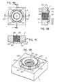
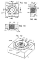
- a hollow body element 200 for attachment to a usually made of sheet metal component 280 (FIG. Fig. 7A respectively. Fig. 7B ) having an at least substantially square or rectangular outer contour 202, with a first broad side 2 and a second broad side 3, with a punching section 246 having an undercut 244 projecting beyond the second broad side and an annular recess 212 is surrounded in the second broad side and with a hole 204 which extends from the first broad side 2 through the punching section 246, wherein the hole optionally has a threaded cylinder 206 and the hollow body element is characterized in that anti-rotation features 272 outside the hollow cylindrical projection 210th and / or inside the annular recess 212 are formed around the hollow cylindrical projection 210 around.
- the hollow body element is further characterized in that the second broad side 3 is located radially outside the annular recess 212 in a plane, i. Apart from any curves or bevels at the transitions in the side edges of the hollow body member, and thus has no beams, grooves or undercuts in the area outside the annular recess.
- the annular recess 212 is designed with an outer diameter which is only slightly smaller than the smallest transverse dimension of the rectangular in plan view hollow body element, whereby the annular recess with the second broad side 3 of the profile at the narrowest points 284, 286 in the plane of the second broadside remaining webs in Range from 0.25 to 1 mm, preferably from about 0.5 mm.
- Figs. 7A and 7B show as one and the same inventive element 200 according to Figs. 5A to 5D with a thinner sheet metal part ( Fig. 7A ), for example, 0.7 mm thick and with a thicker sheet metal part ( Fig. 7B ) of, for example, 1.85 mm thickness can be used.
- the sheet material fills after pressing by means of a die, the entire annular recess 212 and abuts the full surface of the annular recess and the anti-rotation features 272 in the region of the undercut. In both cases, therefore, a good coverage with the anti-rotation ribs 272 and therefore a good anti-rotation between the hollow body member 200 and the sheet metal part 280.
- the flattened end face 224 of the punching section 246 is located at thin sheets (as in Fig. 7A shown) in the height of the underside of the sheet metal part and in thicker sheet metal parts ( Fig. 7B ) above the underside of the sheet metal part (ie, the side of the sheet metal part facing away from the body part of the hollow body element).
- there is an annular recess 282 around the punching section which is predetermined in its shape by the concrete shape of the complementarily shaped die in the self-piercing attachment of the hollow body element in a press or by a robot or in a C-frame.
- the die usually has a central bore, through which the resulting stamping is disposed of.
- the hollow body elements according to the invention are self-piercing, they can still be used in pre-punched sheet metal parts.
- a further thickness range of sheet metal parts for example 1.85 to 3 mm, can be covered. Only the punching section needs to be made longer.
- the square-shaped in hollow body elements are mounted so that the second broad side 3 is applied directly to the top of the sheet metal part 280, but not or substantially not dig into the sheet metal part, a notch effect is not to be feared, so that a good fatigue thanks good fatigue resistance even with dynamic loads.
- the hollow body elements are square in plan view, no special orientation of the die is required per se with respect to the particular setting head used as the punching section is circular in plan view and therefore orientation-free. It only needs to be ensured that the setting head and the die are coaxial with each other and to the longitudinal axis 226 of the hollow body element.
- the further component is usually below the sheet metal part by a screw (not shown) attached, which is screwed coming from below into the thread.
- a screw not shown
- the connection between the hollow body element 200 and the sheet metal part is reinforced by tightening the screw.
- anti-rotation ribs would be conceivable which traverse the annular recess 212 in the radial direction or bridge it, for example in the FIGS 8A-8D .
- Such anti-rotation ribs can be flush with the broad side 3 ( 8A-8D ) or recessed within the annular recess (such anti-rotation features are not shown in the drawings).
- the free upper sides of the anti-rotation ribs which are indicated by 272 ", in the same plane as the surface of the broad side 3 outside the annular recess 212.
- the sides 272" can also be arranged offset from the broad side 3 back. Since the anti-rotation ribs bridge over the annular recess 212, they can also be found on the side of the annular punching section 222 in the region of the undercut 244.
- Figs. 9A-9C show a further variant in which the anti-rotation features in the form of anti-rotation ribs extending in the radial direction over annular recess 212, only the tops of the 272 "'of the anti-rotation ribs 272 of the embodiment according to Figs. 9A-9D inclined so that they rise in the direction of the punching section 222 rising and therefore not only extend in the radial direction over the annular recess and bridge it, but also in the axial direction of the undercut 244 of the punching section 222 over a considerable length or in the full length of the undercut 244 extend.
- the 10A-10D show an embodiment that of the Figs. 9A-9D is very similar, except that here are the anti-rotation ribs angled so that they have a radial portion 272 "" and an axial portion 272 ""', which are interconnected over a radius 272 """and therefore have a total of the discussed angled shape.
- Figs. 11A-11D show another type of anti-rotation features, here in the form of recesses 272 '''' or grooves formed in the inclined side wall of the annular recess 212, wherein the recesses 272 '''' here in plan view have an approximately cup-like shape.
- Other shapes of the depressions are conceivable, for example elongated grooves, which are narrower in the region of the broad side 3.
- FIGs. 12A-12D a slightly different shape of a hollow body element according to the invention.
- the annular recess here has a polygonal shape 212 ', specifically in a concrete case a square shape in plan view, wherein the annular recess has a corresponding number, ie four, inclined surfaces 400, 402, 404 and 406, the by means of radii 408, 410, 412 and 414 into each other pass.
- a surface region which is defined by four corner regions 416, 418, 420 and 422 and is arranged in a plane perpendicular to the central longitudinal axis 226 of the element.
- Punching section 222 transitions over a radius 424 into these corner regions, the radius at the radially outermost point having a diameter which is slightly larger than the maximum transverse dimension of the surface region formed by the four corners 416, 418, 420 and 422 that this radius eventually merges into the bottom of the four sloping surfaces. All thin parallel lines such as 426, 426 'and 426 "show radii or rounded surfaces which provide, inter alia, for a gentle bending of the sheet metal part.
- the rounded areas between the inclined surfaces also have the advantage that there are no pronounced sharp features in these areas in the sheet metal part, which can lead to fatigue, especially under dynamic loading of the component. Since the punching section 222, as in the other embodiments, generates a circular hole in the sheet metal part, no stress concentrations are to be expected here, which can lead to fatigue cracks during operation.
- the element When attaching of the hollow body element to a sheet metal part, the element is at least substantially not deformed, deformation is undesirable, and the sheet metal part by a suitable complementary shape of the die in the square recess 212 'in the area around the punching portion 222 around and completely in contact with this Punching section brought around the punching section around.
- the hollow body element is formed flat on the first broad side 2, ie with an end face which is perpendicular to the central longitudinal axis 226 of the element, according to the previous embodiment of the Fig. 5A-5N .
- the corresponding end face in the embodiments according to 8A-8D to Figs. 12A-12D similar to the embodiment according to Fig. 6D could be trained.
- Both Figs. 12A-12D This means that instead of a circular survey as in Fig. 6D shown, the survey will then have a corresponding polygonal shape, here a square shape.
- the hollow cylindrical projection which is converted by flattening in the punching section 222, solely by material displacement from the second broad side 3 of the hollow body element to reach, that is, it is not necessary to perform in the first step of the manufacturing process, a penetration method in which material from the first broadside 2 shifted from becomes.
- the first manufacturing step a) according to claim 1 can be replaced here by a molding process in which the hollow cylindrical projection 210 is effected solely by material displacement from the region of the polygonal ring recess in plan view and in the region of the hollow cylindrical projection 210.
- the body thus formed is then pierced through from the first broad side 2 to the bottom 216 of the cavity 232.
- the present invention is intended for the production of rectangular or square elements in the outer contour, it could also be used for the production of polygonal, oval or circular elements in the outer contour or of another shape, provided the tools used are designed to be the profile strip to produce the desired contour shape, for example by the use of appropriately designed punching tools.
- annular recess 212 need not necessarily be simultaneous with the piercing operation, but could be combined with the piercing or flattening process, i. the punches 84, 86 and the flattening dies 88, 90 would have to have a corresponding shape in this case.
- the profile can be maintained or used after production of the general shape of the hollow body elements in sections or in rewound form, with a separation into individual hollow body elements takes place only when the profile in a setting head for attachment of the hollow body elements is used on a component.
Abstract
Description
Die vorliegende Erfindung betrifft ein Verfahren zur Herstellung von Hohlkörperelementen, wie Mutterelemente, zur Anbringung an üblicherweise aus Blech bestehenden Bauteilen, insbesondere zur Herstellung von Hohlkörperelementen mit einem zumindest im Wesentlichen quadratischen oder rechteckigen Außenumriss, durch Ablängung einzelner Elemente von einem in Form einer Profilstange oder eines Wickels vorliegenden Profil nach vorheriger Stanzung von Löchern in das Profil, gegebenenfalls mit anschließender Ausbildung eines Gewindezylinders unter Anwendung eines Folgeverbundwerkzeugs mit mehreren Arbeitsstationen, in denen jeweilige Bearbeitungen durchgeführt werden. Weiterhin betrifft die vorliegende Erfindung Hohlkörperelemente, die nach dem Verfahren hergestellt werden, Zusammenbauteile, die aus einem Hohlkörperelement und einem Blechteil bestehen sowie ein Folgeverbundwerkzeug zum Durchführen des Verfahrens.The present invention relates to a method for producing hollow body elements, such as nut elements, for attachment to usually made of sheet metal components, in particular for the production of hollow body elements with an at least substantially square or rectangular outer contour, by cutting individual elements of one in the form of a profile bar or a Wickels present profile after prior punching of holes in the profile, optionally with subsequent formation of a threaded cylinder using a progressive tool with multiple workstations in which respective operations are performed. Furthermore, the present invention relates to hollow body elements, which are produced by the method, assembly components, which consist of a hollow body member and a sheet metal part and a follow-on composite tool for performing the method.
Ein Verfahren der eingangs genannten Art sowie entsprechende Hohlkörperelemente und Zusammenbauteile sind beispielsweise aus der
Aufgabe der vorliegenden Erfindung ist es, das Verfahren der eingangs genannten Art so weiter zu entwickeln, dass Hohlkörperelemente, insbesondere rechteckige Mutterelemente, preisgünstig hergestellt werden können, ohne die verwendete Werkzeuge so zu belasten, dass sie frühzeitig versagen. Ferner sollten die Hohlkörperelemente mechanische Eigenschaften haben, die denen der Hohlkörperelemente, die nach der
Die erfindungsgemäße Aufgabe wird durch ein Verfahren der eingangs genannten Art gelöst, das durch die folgenden Schritte gekennzeichnet ist:
- a) dass in einem ersten Schritt ausgehend von einem im Querschnitt rechteckigen Profil ein Durchsetzvorgang durchgeführt wird, der zu einer zylindrischen Vertiefung an einer ersten Breitseite des Profils und einem hohlzylindrischen Vorsprung an einer zweiten der ersten Breiteseite gegenüber liegenden Breitseite des Profils führt, der von einer ringförmigen Vertiefung umgeben ist,
- b) dass in einem zweiten Schritt ein zwischen dem Boden der zylindrischen Vertiefung und dem Boden des hohlzylindrischen Vorsprungs verbleibender Steg zur Ausbildung eines durchgehenden Loches durchlocht bzw. herausgestanzt wird,
- c) dass in einem dritten Schritt, der gegebenenfalls mit dem Schritt b) kombiniert werden kann, der hohlzylindrische Vorsprung an seinem freien Stirnende zur Ausbildung eines auf der Außenseite hinterschnittenen Stanzabschnitts abgeflacht bzw. gequetscht wird, wonach die Hohlkörperelemente vom Profil abgetrennt und gegebenenfalls mit Gewinde versehen werden.
- a) that in a first step, starting from a rectangular cross-section profile, a penetration is performed, which leads to a cylindrical recess on a first broad side of the profile and a hollow cylindrical projection on a second of the first broadside opposite broad side of the profile of a surrounded by a ring-shaped depression,
- b) that in a second step a web remaining between the bottom of the cylindrical recess and the bottom of the hollow cylindrical projection is pierced or punched out to form a through hole,
- c) that in a third step, which may optionally be combined with step b), the hollow cylindrical projection is flattened or crimped at its free front end to form an undercut on the outside punching section, after which the hollow body elements separated from the profile and possibly threaded be provided.
Ferner sieht die vorliegende Erfindung ein Hohlkörperelement zur Anbringung an einem üblicherweise aus Blech bestehenden Bauteil vor, insbesondere mit einem zumindest im Wesentlichen quadratischen oder rechteckigen Außenumriss, mit einer ersten Breitseite und einer zweiten Breitseite, mit einem eine Hinterschneidung aufweisenden Stanzabschnitt, der über die zweite Breitseite vorsteht und von einer Ringvertiefung in der zweiten Breitseite umgeben ist sowie mit einem Loch, das sich von der ersten Breitseite durch den Stanzabschnitt hindurch erstreckt, wobei das Loch gegebenenfalls einen Gewindezylinder aufweist, dadurch gekennzeichnet dass Verdrehsicherungsmerkmale außen am hohlzylindrischen Vorsprung und/oder innen im Bereich der Ringvertiefung um den hohlzylindrischen Vorsprung herum ausgebildet werden.Furthermore, the present invention provides a hollow body element for attachment to a usually made of sheet metal component, in particular with an at least substantially square or rectangular outer contour, with a first broad side and a second broad side, with an undercut having punching section, on the second broad side projecting and surrounded by an annular recess in the second broad side and with a hole extending from the first broad side through the punching section, wherein the hole optionally has a threaded cylinder, characterized in that anti-rotation features on the outside of the hollow cylindrical projection and / or inside in the area the annular recess are formed around the hollow cylindrical projection around.
Bei dem erfindungsgemäßen Verfahren weist das verwendete Profil somit einen rechteckigen Querschnitt auf und ist daher preisgünstig herzustellen. Durch die Schritte a), b) und c) gelingt es, Hohlkörperelemente herzustellen, ohne dass die verwendeten Werkzeuge einem hohen Verschleiß unterliegen und ohne dass die verwendeten Stempel vorzeitig versagen. Das in der deutschen Patentanmeldung
Die Herstellung in Arbeitsschritten, bei denen für ein Profil immer zwei Bearbeitungen in einer Station durchgeführt werden, führt dazu, dass die Produktivität der Herstellungsanlage verdoppelt wird, ohne dass der Aufwand für die Herstellung des Folgeverbundwerkzeugs in einem Ausmaß steigt, das nicht mehr vertretbar wäre. Zwar wird durch die Verdopplung von Arbeitselementen ein gewisser Mehraufwand erforderlich, dieser lässt sich aber über entsprechende Fertigungszahlen ohne weiteres relativ früh amortisieren.The production in steps, in which for a profile always two operations are performed in a station, resulting in the productivity of the manufacturing plant is doubled, without increasing the cost of producing the progressive compound tool to an extent that would be no longer justifiable. Although a doubling of effort is required by the doubling of work elements, but this can easily be amortized relatively early on corresponding production figures.
Es ist zwar möglich, in einem Folgeverbundwerkzeug mehrere Profile parallel zu bearbeiten, dies ist allerdings nicht unbedingt vorzuziehen, da bei auftretenden Problemen mit einem Profil bzw. mit der Bearbeitung eines Profils, das gesamte Folgeverbundwerkzeug bis zur Behebung der Störung angehalten werden muss, wodurch erhebliche Produktionseinbußen entstehen könnten. Nichtsdestotrotz könnte die vorliegende Erfindung unter Anwendung eines Folgeverbundwerkzeugs realisiert werden, das mehrere Profile gleichzeitig bearbeitet.Although it is possible to process several profiles in parallel in a follow-on composite tool, this is not necessarily preferable, since problems that occur with a profile or with the processing of a profile, the entire follow-on composite tool must be stopped until the disturbance, resulting in significant Production losses could arise. Nonetheless, the present invention could be implemented using a progressive tool that processes multiple profiles simultaneously.
Besonders bevorzugte Ausführungen des erfindungsgemäßen Verfahrens, der erfindungsgemäßen Hohlkörperelemente, der erfindungsgemäßen Zusammenbauteile sowie des erfindungsgemäßen Folgeverbundwerkzeugs lassen sich den weiteren Patentansprüchen entnehmen.Particularly preferred embodiments of the method according to the invention, the hollow body elements according to the invention, the assembly parts according to the invention as well as the follow-on composite tool according to the invention can be taken from the further claims.
Weitere Vorteile des erfindungsgemäßen Verfahrens, der erfindungsgemäßen Hohlkörperelemente sowie des erfindungsgemäß verwendeten Folgeverbundwerkzeug lassen sich den Figuren und der anschließenden Figurenbeschreibung entnehmen.Further advantages of the method according to the invention, the hollow body elements according to the invention as well as the follow-on composite tool used according to the invention can be taken from the figures and the subsequent description of the figures.
Die Figuren zeigen:
- Fig. 1
- eine Ausführung eines Profils, das zum Zwecke der vorliegenden Erfindung in einem Folgeverbundwerkzeug entsprechend der
Figur 2 - Fig. 2
- eine in Bewegungsrichtung des Profils geschnittene Darstellung eines Folgeverbundwerkzeugs wiedergibt,
- Fig. 3
- eine vergrößerte Darstellung des Folgeverbundwerkzeugs der
Fig. 2 im Bereich der Arbeitsstationen, - Fig. 4A-4E
- eine Darstellung der einzelnen Schritte der Herstellung eines erfindungsgemäßen Hohlkörperelements unter Anwendung des erfindungsgemäßen Verfahrens und des Folgeverbundwerkzeugs der
Fig. 2 und3 , - Fig. 5A-5N
- verschiedene Darstellungen des fertig gestellten erfindungsgemäßen Hohlkörperelements der
Fig. 4A-4E , wobeiFig. 5A eine perspektivische Darstellung des erfindungsgemäßen Hohlkörperelements von unten zeigt,Fig. 5B eine Draufsicht auf das erfindungsgemäße Hohlkörperelement von oben,Fig. 5C eine Schnittzeichnung entsprechend der Schnittebene C-C bzw. C'-C' derFig. 5B und Fig. 5D eine vergrößerte Darstellung des Bereichs D derFig. 5C , die weitereFiguren 5E-5I zeigen eine ideale Variante des Hohlkörperelements derFig. 5A-5D und zwar ausgelegt für dickere Blechteilen während dieFig. 5J-5N eine weitere ideale Variante, die zur Anwendung mit dünneren Blechteilen ausgelegt ist,
- Fig. 6A-6E
- Darstellungen eines weiteren erfindungsgemäßen Hohlkörperelements, das eine leichte Abwandlung des Hohlkörperelements gemäß
Fig. 5A-5D darstellt, wobeiFig. 6A eine Draufsicht auf das Hohlkörperelement von oben zeigt,Fig. 6B eine Schnittzeichnung entlang der Schnittebene B-B derFig. 6A, Fig. 6C eine Schnittzeichnung entsprechend der Schnittebene C-C derFig. 6A wiedergibt undFig. 6D und 6E perspektivische Darstellungen des Funktionselements von oben und unten sind, - Fig. 7A-7B
- die Anbringung des erfindungsgemäßen Hohlkörperelements an einem dünnen Blechteil bzw. einem dickeren Blechteil,
- Fig. 8A-8D
- Darstellungen einer weiteren Ausführungsvariante eines Hohlkörperelements mit Verdrehsicherungsmerkmale in Form von sich radial erstreckenden Rippen, die die Ringvertiefung überbrücken, wobei die
Fig. 8A eine Ansicht auf das Hohlkörperelement von unten, dieFig. 8B und 8C Schnittzeichnungen entsprechend der horizontalen Schnittebene B-B bzw. der senkrechten Schnittebene C-C derFig. 8A und dieFig.8D eine perspektivische Zeichnung ist bzw. sind, - Fig. 9A-9D
- Darstellungen entsprechend den
Fig. 8A-8D jedoch von einer Ausführungsform mit schräg gestellten Verdrehsicherungsrippen, die sich in radialer Richtung über die Ringvertiefung und in axialer Richtung an der Hinterschneidung des Stanzabschnitts entlang erstrecken,
- Fig. 10A-10D
- Darstellungen entsprechend den
Fig. 8A-8D jedoch von einer Ausführungsform mit abgewinkelten Verdrehsicherungsrippen, die sich in radialer Richtung über die Ringvertiefung und in axialer Richtung an der Hinter schneidung des Stanzabschnitts entlang erstrecken, - Fig. 11A-11D
- Darstellungen entsprechend den
Fig. 8A-8D jedoch von einer Ausführungsform mit Verdrehsicherungsmerkmalen die durch Nuten bzw. Vertiefungen gebildet sind, und - Fig. 12A-12D
- Darstellungen entsprechend den
Fig. 8A-8D jedoch von einer Ausführungsform mit einer in Draufsicht polygonalen Ringform, in konkretem Fall von quadratischer Form.
- Fig. 1
- an embodiment of a profile, for the purpose of the present invention in a progressive tool according to the
FIG. 2 is processed, the - Fig. 2
- a representation of a follow-on composite tool cut in the direction of movement of the profile,
- Fig. 3
- an enlarged view of the progressive tool of the
Fig. 2 in the field of workstations, - Fig. 4A-4E
- a representation of the individual steps of the production of a hollow body element according to the invention using the method according to the invention and the follow-on composite tool of
Fig. 2 and3 . - Fig. 5A-5N
- various representations of the finished hollow body element according to the invention
Fig. 4A-4E , in whichFig. 5A shows a perspective view of the hollow body element according to the invention from below,Fig. 5B a top view of the hollow body element according to the invention from above,Fig. 5C a sectional view corresponding to the sectional plane CC or C'-C 'theFIGS. 5B and 5D an enlarged view of the area D ofFig. 5C , the moreFigures 5E-5I show an ideal variant of the hollow body element ofFigs. 5A-5D and designed for thicker sheet metal parts during theFigs. 5J-5N another ideal variant, which is designed for use with thinner sheet metal parts,
- Figs. 6A-6E
- Representations of another hollow body element according to the invention, which is a slight modification of the hollow body element according to
Figs. 5A-5D represents, whereFig. 6A shows a plan view of the hollow body element from above,Fig. 6B a sectional view along the section plane BB ofFig. 6A, Fig. 6C a sectional view corresponding to the sectional plane CC ofFig. 6A reproduces andFIGS. 6D and 6E are perspective views of the functional element from above and below, - Figs. 7A-7B
- the attachment of the hollow body element according to the invention on a thin sheet metal part or a thicker sheet metal part,
- 8A-8D
- Representations of another embodiment of a hollow body element with anti-rotation features in the form of radially extending ribs that bridge the annular recess, wherein the
Fig. 8A a view of the hollow body element from below, theFigs. 8B and 8C Sectional drawings corresponding to the horizontal section plane BB or the vertical section plane CC of theFig. 8A and theFigure 8D is a perspective drawing, - Figs. 9A-9D
- Representations according to the
8A-8D However, from an embodiment with inclined anti-rotation ribs extending in the radial direction over the annular recess and in the axial direction along the undercut of the punching section,
- 10A-10D
- Representations according to the
8A-8D However, of an embodiment with angled anti-rotation ribs extending in the radial direction over the annular recess and in the axial direction of the rear section of the punching section along, - Figs. 11A-11D
- Representations according to the
8A-8D but of an embodiment with anti-rotation features formed by grooves or depressions, and - Figs. 12A-12D
- Representations according to the
8A-8D but of an embodiment with a polygonal in plan view ring shape, in concrete case of square shape.
Ein erstes Folgeverbundwerkzeug 10, das zur Herstellung von Hohlkörperelementen aus dem Profil 21 der
Man sieht aus
In der ersten Station A wird als erster Schritt a) ein so genannter Durchsetzvorgang durchgeführt.In the first station A, a so-called enforcing procedure is carried out as the first step a).
In der zweiten Arbeitsstation B wird in einem zweiten Schritt b) ein Lochvorgang und in der dritten Arbeitsstation C in einem dritten Schritt c) ein Quetsch- bzw. Abflachvorgang durchgeführt. Schließlich wird in der vierten Arbeitsstation D ein Abschlagstempel 22 verwendet, um zwei Hohlkörperelemente bei jedem Hub der Presse vom Profil 1 abzutrennen. Dabei schneidet die rechte Seite des Stempels das Profil an einer Trennstelle durch, die sich hinter dem ersten Hohlkörperelement, d.h. dem Hohlkörperelement 21 in
Das zweite Hohlkörperelement 21' fällt durch ein Loch 28 in der Abschlagmatrize 30 und anschließend durch entsprechende Bohrungen 32, 34, 36 und 38 hindurch, die in Platten 40, 42, 44 und 12 ausgebildet sind.The second hollow body member 21 'passes through a
Die Bohrungen bzw. das Loch 38 in der Platte 12 können mit einer weiteren Bohrung (nicht gezeigt) im Pressentisch oder in einer etwaig vorgesehenen Zwischenplatte zwischen der Platte 12 und dem Pressentisch führen, die die Herausführung der Mutterelemente wie 21' ermöglicht, beispielsweise unter der Einwirkung der Schwerkraft oder über eine seitliche Rutsche oder unter Anwendung eines Druckluftstoßes.The bores or the
Bei der konkreten, in
An mehreren Stellen zwischen der durchgehenden Platte 44 und den Plattenabschnitten 50, 52, 54, 56, 58 und 60 befinden sich kräftige Schraubendruckfedern 62, von denen nur die eine Feder in den
Die Trennebene des Folgeverbundwerkzeugs befindet sich oberhalb des Profils 1 und ist mit T in
Oberhalb des Profilstreifens befinden sich wiederum Plattenabschnitte 72, 74, 76, 78 und 80, die mit einer durchgehenden Platte 82 verschraubt sind - auch hier über nicht dargestellte Schrauben. Ferner ist die Platte 82 mit der oberen Platte 16 verschraubt.Above the profile strip are in
Bei Öffnung der Presse werden somit die Platten 72, 74, 76, 78 und 80 mit der Platte 22 und der oberen Platte 16 angehoben, und zwar so weit, dass die zwei Lochstempel 84, 86 und die zwei oberen Abflachstempel 88 und 90, wie auch die Matrizen 92 und 94, die mit den Durchsetzstempel 64, 66 zusammenarbeiten und auch der Abschlagstempel 22 außer Eingriff mit dem Profilstreifen 1 gelangen. Durch diese Bewegung, gekoppelt mit der Anhebung des Profilstreifens durch die Feder 62, wird es ermöglicht, dass der Profilstreifen 1 um die doppelte Längenabmessung der Hohlkörperelemente 21 weiter geschoben werden kann in Vorbereitung für den nächsten Hub der Presse.Upon opening of the press, the
Man sieht, dass die Arbeitsstationen A und B eine Längenabmessung, d.h. in Bewegungsrichtung 20 des Profilstreifens 1, aufweisen, die der vierfachen Längenabmessung eines Hohlkörperelements 21 entspricht. Die Arbeitsstation C hat eine Längenabmessung, die der dreifachen Längenabmessung eines Hohlkörperelementes 21 entspricht, während die Arbeitsstation D eine Längenabmessung aufweist, die ein mehrfaches der Längenabmessung des Hohlkörperelements 21, in diesem Beispiel das sechsfache, aufweist. Dies bedeutet, dass so genannte leere Stellen wie 98 vorhanden sind, an denen keine Bearbeitung des Profilstreifens 1 stattfindet. Diese leeren Stellen schaffen aber Platz, der notwendig ist, um die einzelnen Bestandteile der verwendeten Werkzeuge ausreichend stabil auszubilden und abzustützen.It can be seen that workstations A and B have a length dimension, i. in the direction of
Ferner sieht man aus
Obwohl hier nicht gezeigt, befinden sich links und rechts des Profilstreifens 1, d.h. hinter der Ebene der Zeichnung vor der Ebene der Zeichnung der
Die konstruktiven Einzelheiten der Durchsetzstempel 64, 66, der damit zusammen arbeitenden Matrizen 92, 94, der Lochstempel 84, 86 der damit zusammen wirkenden Matrizen 100, 102 und der Abflachstempel 88, 90 gehen aus den Zeichnungen der
Mittels der Folgeverbundwerkzeuge der
In der letzten Arbeitsstation werden mittels eines Abschlagstempels 22 von dem bzw. von jedem Profil 1 jeweils zwei Hohlkörperelemente 21, 21' abgetrennt.In the last workstation, two
Der Abschlagstempel 22 durchtrennt das Profil an einer ersten Stelle hinter einem ersten Hohlkörperelement 21 und an einer zweiten Stelle hinter einem zweiten Hohlkörperelement 21', wobei das zweite Hohlkörperelement 21' in Richtung der Bewegung des Abschlagstempels quer zur Längsrichtung des Profils 1 aus der Bewegungsbahn des Profils herausgeführt wird. Das erste Hohlkörperelement 21 wird in der Abschlagstation des Folgeverbundwerkzeugs zumindest vorerst im Allgemeinen in Richtung der Bewegungsbahn des Profils herausgeführt.The knock-
Jede Arbeitsstation des Folgeverbundwerkzeugs weist eine Länge in Laufrichtung des Profils auf, die dem Dreifachen oder dem Vierfachen oder dem Mehrfachen der Längsabmessung eines fertigen Hohlkörperelements 21, 21' entspricht.Each workstation of the follow-on composite tool has a length in the direction of travel of the profile which corresponds to three times or four times or several times the longitudinal dimension of a finished
Bei der gezeigten Ausführung des Folgeverbundwerkzeugs wird eine gefederte Nocke 27 mit einer zur Bewegungsbahn des Profils schräggestellten Nockenfläche 24 von der vorderen Kante des vorderen Endes des Profils am Ausgangsende der letzten Arbeitsstation entgegen der Kraft einer Federeinrichtung 26 vorgespannt. Nach Abtrennung des am vorderen Ende des Profils ausgebildeten Hohlkörperelements 21 wird dieses von der gefederten Nocke nach unten gekippt, um die Entfernung aus dem Folgeverbundwerkzeug zu erleichtern.In the illustrated embodiment of the progressive tool, a spring-loaded
Bei der Ausführung gemäß
Es werden nun einige Beispiele angegeben, die die Herstellung von bestimmten Hohlkörperelementen beschreiben.Some examples will now be given describing the production of certain hollow body elements.
Bezug nehmend auf die
- a) In einem ersten Schritt, ausgehend von einem im Querschnitt rechteckigem Profil 1,
Fig. 4A ), wird ein Durchsetzvorgang unter Anwendung der Durchsetzmatrizen 92, 94, die von oben kommen, und der Durchsetzstempel 64, 66 durchgeführt. Der Durchsetzvorgang führt zu einer zylindrischen Vertiefung 208 an einer ersten Breitseite 2 des Profils 1 und einem hohlzylindrischen Vorsprung 210 an einer zweiten, der ersten Breiteseite 2 gegenüber liegenden Breitseite 3 des Profils, der von einer ringförmigen Vertiefung 212 umgeben ist, die inFig. 4B gezeigt ist. Der Profilstreifen 1 wird beim Schließen der Presse bzw. des Folgeverbundwerkzeugs auf die oberhalb des Plattenabschnitts 52 hervorstehenden Enden der Durchsetzstempel 64 und 66 gedrückt. Die hervorstehenden Enden der Durchsetzstempel haben eine zu der Form der zylindrischen Vertiefung 208, die inFig. 4B gezeigt ist komplementäre Form. In ähnlicher Weise haben die Stirnenden der mit dem Durchsetzstempel zusammen arbeitenden Matrizen 92, 94 eine zu der des hohlzylindrischen Vorsprungs 210 und der diese umgebenden Ringvertiefung 212 gemäßFig. 4B komplementäre Form. - b) In einem zweiten Schritt wird ein
zwischen dem Boden 214 der zylindrischen Vertiefung 208und dem Boden 216 des hohlzylindrischen Vorsprungs 210verbleibender Steg 218 beim Schließen der Presse bzw. des Folgeverbundwerkzeugs 10 mittels der Lochstempel 88, 90 zur Ausbildung des durchgehenden Loches 204 (Fig. 4C ) durchlocht. Die Stanzbutzen werden wie erwähnt über die Bohrungen 104, 106 bzw. 108, 110 entsorgt. - c) In einem dritten Schritt wird der hohlzylindrische Vorsprung 210 an seinem freien Stirnende 220 zur Ausbildung eines auf der Außenseite hinterschnittenen Stanzabschnitts 222 abgeflacht, wodurch die
Stirnfläche 224 inFig. 4D ausgebildet wird, die in einer Ebene parallelzu den Breitseiten 2 und 3 und senkrecht zur mittleren Längsachse 226 desLochs 204 steht. Danach können die Hohlkörperelemente in der Arbeitsstation D vom Profil abgetrennt und anschließend gegebenenfallsmit Gewinde 206 versehen werden, wie inFig. 4E bzw. in der dazu identischenFig. 5C gezeigt.
- a) in a first step, starting from a profile 1 which is rectangular in cross-section,
Fig. 4A ), a piercing action is achieved using the piercing dies 92, 94 coming from the top, and thepuncture punch 64, 66 performed. The passage leads to acylindrical recess 208 at a firstbroad side 2 of the profile 1 and a hollowcylindrical projection 210 at a second, thefirst width side 2 oppositebroad side 3 of the profile, which is surrounded by anannular recess 212 which inFig. 4B is shown. The profile strip 1 is pressed when closing the press or the progressive tool on the protruding above theplate portion 52 ends of the puncturing punches 64 and 66. The protruding ends of the puncturing punches have a shape similar to that of thecylindrical recess 208 shown in FIGFig. 4B shown is complementary shape. Similarly, the front ends of the dies 92, 94 cooperating with the punching punch have aring groove 212 corresponding to that of the hollowcylindrical projection 210 and theannular recess 212 surrounding itFig. 4B complementary form. - b) In a second step, a
web 218 remaining between the bottom 214 of thecylindrical recess 208 and thebottom 216 of the hollowcylindrical projection 210 when the press or follow-on composite tool 10 is closed by means of the punches 88, 90 to form the through hole 204 (FIG.Fig. 4C ). The punched slugs are disposed of as mentioned above the holes 104, 106 and 108, 110. - c) In a third step, the hollow
cylindrical projection 210 is flattened at its freefront end 220 to form an undercut on theoutside punching section 222, whereby theend face 224 inFig. 4D is formed, which is in a plane parallel to thebroad sides longitudinal axis 226 of thehole 204. Thereafter, the hollow body elements separated in the work station D from the profile and then optionally provided withthread 206, as inFig. 4E or in the identicalFig. 5C shown.
Der dritte Schritt könnte gegebenenfalls mit dem Schritt b) kombiniert werden.The third step could optionally be combined with step b).
Beim Durchsetzvorgang des Schrittes a) werden der Durchmesser der zylindrischen Vertiefung und der innere Durchmesser des hohlzylindrischen Vorsprungs zumindest im Wesentlichen gleich ausgeführt.During the passage of step a), the diameter of the cylindrical recess and the inner diameter of the hollow cylindrical projection are at least substantially equal.
Ferner wird vorzugsweise beim Durchsetzvorgang des Schrittes a) oder beim Lochvorgang des Schritts b) oder beim Abflachvorgang des Schritts c) die Mündung 229 der zylindrischen Vertiefung 208 an der ersten Breitseite 2 des Profils mit einer gerundeten oder angefasten Einlaufkante 230 ausgeführt, die bei Verwendung des Elements den Gewindeauslauf bildet.Furthermore, the mouth 229 of the
Beim Durchsetzvorgang des Schrittes a) oder beim Lochvorgang des Schrittes b) oder beim Abflachvorgang des Schrittes c) wird vorzugsweise auch die Mündung 232 des hohlzylindrischen Vorsprungs 210 an ihrem freien Ende mit einer gerundeten oder angefasten Auslaufkante 234 versehen, die beim fertig gestellten Element den Gewindeeinlauf bildet.During the passage of step a) or the hole process of step b) or the flattening of step c) is preferably also the
Bei der Durchlochung des Steges gemäß Schritt b) wird das Loch 204 mit einem Durchmesser erzeugt, der dem Durchmesser der zylindrischen Vertiefung 208 und dem inneren Durchmesser des hohlzylindrischen Vorsprungs 210 zumindest im Wesentlichen entspricht. Ferner wird beim Durchsetzvorgang des ersten Schrittes a) das freie Ende des hohlzylindrischen Vorsprungs 210 außen mit einer Fase 236 versehen. Außerdem wird bei diesem Durchsetzvorgang die Ringvertiefung 212 mit einem ringförmigen Bodenbereich 238 versehen, der zumindest in etwa in einer Ebene parallel zu der ersten und zweiten Breitseite 2, 3 des Profilstreifens steht, auf der radial inneren Seite mit einem zumindest im Wesentlichen gerundeten Übergang 240 in die Außenseite des hohlzylindrischen Vorsprungs 210 und auf der radial äußeren Seite in eine konusförmige Fläche 242 übergeht, die einen eingeschlossenen Konuswinkel im Bereich zwischen 60 bis 120°, vorzugsweise bei etwa 90° aufweist.When piercing the web according to step b), the
Der Übergang 243 vom ringförmigen Bereich 238 der Ringvertiefung 212 in die konusförmige Fläche 242 wird gerundet, wie auch der Auslauf 245 der Konusfläche der Ringvertiefung 212 in die zweite Breitseite 3 des Profils. Die Konusfläche 242 kann sich in der Praxis so darstellen, dass der gerundete Übergang 243 tangential in den gerundeten Auslauf 245 übergeht.The
Bei Herstellung der Hinterschneidung 244 wird diese durch einen zylindrischen Teil des hohlzylindrischen Vorsprungs 210 gebildet, der in etwa in der Höhe der zweiten Breitseite 3 des Profils 1 in einen bei Durchführung des Schrittes c) verdickten Bereich 246 des hohlzylindrischen Vorsprungs 210 übergeht, der zumindest im Wesentlichen über die zweite Breitseite 3 des Profils vorsteht.When the undercut 244 is produced, it is formed by a cylindrical part of the hollow
Der verdickte Bereich 246 des hohlzylindrischen Vorsprungs 210 wird zumindest im Wesentlichen konusförmig ausgeführt und divergiert von der ersten und zweiten Breitseite weg, wobei der Konuswinkel des verdickten Bereichs des hohlzylindrischen Vorsprungs benachbart zur Stirnseite 224 im Bereich zwischen 30° und 70°, vorzugsweise bei etwa 50° liegt. Nach dem Abflachungsvorgang endet der hohlzylindrische Vorsprung 219 an seinem freien Ende außen in einer möglichst scharfkantigen Stanzkante 250.The thickened
Wie insbesondere aus den
Die
In den
Der Hauptunterschied zwischen der Ausführung gemäß
Konkret zeigt die
Die
Dies stellt einen Unterschied zu der Stirnseite 224 der Ausführung gemäß
Ferner ist insbesondere aus den Zeichnungen gemäß
Durch die Verwendung der gleichen Bezugszeichen ist erkennbar, dass die
In einem alternativen Verfahren, das zu dem Hohlkörperelement nach den
Der Boden der Ringvertiefung ist in dieser Ausführungsform allein durch einen gerundeten Übergang 243 vom hohlzylindrischen Vorsprung 210 in die Konusfläche 242 gebildet, was auch bei der Ausführung gemäß
Beim Durchsetzvorgang gemäß Schritt a) werden, wie in
Diese Verdrehsicherungsmerkmale können (wie gezeigt) durch Rippen 272 und/oder Nuten (nicht gezeigt) an der radial äußeren Seite des hohlzylindrischen Vorsprungs 210 gebildet werden. Diese Rippen 272 erstrecken sich in axialer Richtung 226 und überbrücken die Hinterschneidung 244 des hohlzylindrischen Vorsprungs 210. Sie haben eine radiale Breite, die zumindest im Wesentlichen im Bereich zwischen 40 % und 90 % der maximalen radialen Tiefe der Hinterschneidung entspricht.These anti-rotation features may be formed by
Es entsteht somit ein Hohlkörperelement 200 zur Anbringung an einem üblicherweise aus Blech bestehenden Bauteil 280 (
Das Hohlkörperelement zeichnet sich ferner dadurch aus, dass die zweite Breitseite 3 radial außerhalb der Ringvertiefung 212 in einer Ebene liegt, d.h. abgesehen von etwaigen Rundungen oder Fasen an den Übergängen in die Seitenflanken des Hohlkörperelements, und somit keine Balken, Nuten oder Hinterschneidungen im Bereich außerhalb der Ringvertiefung aufweist.The hollow body element is further characterized in that the second
Die Ringvertiefung 212 ist mit einem Außendurchmesser ausgeführt, der nur etwas kleiner ist als die kleinste Querabmessung des in Draufsicht rechteckigen Hohlkörperelements, wodurch die Ringvertiefung mit der zweiten Breitseite 3 des Profils an den engsten Stellen 284, 286 in der Ebene der zweiten Breitseite verbleibende Stege im Bereich von 0,25 bis 1 mm, vorzugsweise von etwa 0,5 mm bildet.The
Die
Da die in Draufsicht quadratischen Hohlkörperelemente so angebracht werden, dass die zweite Breitseite 3 direkt an der Oberseite des Blechteils 280 anliegt, sich jedoch nicht oder im Wesentlichen nicht in das Blechteil eingräbt, ist eine Kerbwirkung nicht zu befürchten, so dass sich ein gutes Ermüdungsverhalten dank eines guten Ermüdungswiderstands auch bei dynamischen Lasten ergibt. Obwohl die Hohlkörperelemente in Draufsicht quadratisch sind, ist an sich keine besondere Orientierung der Matrize gegenüber dem jeweils verwendeten Setzkopf erforderlich da der Stanzabschnitt in Draufsicht kreisrund und daher orientierungsfrei ist. Es muss nur dafür gesorgt werden, dass der Setzkopf und die Matrize koaxial zueinander und zu der Längsachse 226 des Hohlkörperelements liegen. Bei Anbringung eines weiteres Bauteils an einem Zusammenbauteil gemäß
Ferner ist darauf hinzuweisen, dass Verdrehsicherungsrippen denkbar wären, die in radialer Richtung die Ringvertiefung 212 überqueren bzw. diese überbrücken, wie beispielsweise in den
Bei der Ausführungsform gemäß
Die
Die
Die
Schließlich zeigen die
Der wesentliche Unterschied bei der Formgebung des Hohlkörperelements der Ausführung gemäß
Bei dieser Ausführungsform ist es nicht erforderlich, getrennte Verdrehsicherungsrippen vorzusehen, da die polygonale Form der Ringvertiefung 212' selbst für die erforderliche Verdrehsicherheit sorgt. Diese Ausführung ist auch vorteilhaft, weil die schräg gestellten Flächen und auch die Eckbereiche im Bodenbereich der Ringvertiefung zu der Anlagefläche des Elements gehören, so dass mit entsprechend niedrigen Flächenpressungen am Blechteil gearbeitet werden kann und die Gefahr des Nachsitzens des Elements nicht gegeben ist. Dennoch können hohe Verdrehsicherungswerte erreicht werden, wie auch ein hoher Herausziehwiderstand.In this embodiment, it is not necessary to provide separate anti-rotation ribs, since the polygonal shape of the annular recess 212 'itself provides the required anti-rotation. This embodiment is also advantageous because the inclined surfaces and the corner regions in the bottom region of the annular recess belong to the contact surface of the element, so that can be used with correspondingly low surface pressures on the sheet metal part and the risk of Nachsitzens the element is not given. Nevertheless, high anti-rotation values can be achieved, as well as a high pull-out resistance.
Die gerundeten Bereiche zwischen den schräg gestellten Flächen haben auch den Vorteil, dass an diesen Stellen im Blechteil keine ausgeprägten scharfen Merkmale vorliegen, die zu Ermüdung führen können, insbesondere bei dynamischer Belastung des Bauteils. Da der Stanzabschnitt 222, wie bei den anderen Ausführungsformen, ein kreisrundes Loch im Blechteil erzeugt, sind auch hier keine Spannungskonzentrationen zu erwarten, die im Betrieb zu Ermüdungsrissen führen können. Bei der Anbringung des Hohlkörperelements an ein Blechteil wird das Element zumindest im Wesentlichen nicht verformt, eine Verformung ist unerwünscht, und das Blechteil wird durch eine geeignete komplementäre Form der Matrize in die quadratischen Vertiefung 212' in dem Bereich um den Stanzabschnitt 222 herum und vollständig in Anlage mit diesem Stanzabschnitt um den Stanzabschnitt herum gebracht.The rounded areas between the inclined surfaces also have the advantage that there are no pronounced sharp features in these areas in the sheet metal part, which can lead to fatigue, especially under dynamic loading of the component. Since the
Bei allen Ausführungsformen der
Wenn in dieser Anmeldung von einer polygonalen Gestalt die Rede ist, so umfasst dies auf jeden Fall Polygone mit drei bis zwölf Polygonalflächen, d.h. schräg gestellte Flächen.In this application, when talking about a polygonal shape, this definitely includes polygons having three to twelve polygonal faces, i. inclined surfaces.
Bei der Ausführungsform gemäß
Obwohl die vorliegende Erfindung für die Herstellung von im Außenumriss rechteckigen oder quadratischen Elementen gedacht ist, könnte sie auch zur Herstellung von im Außenumriss polygonalen, ovalen oder kreisrunden Elementen oder von solchen mit einer anderen Form verwendet werden, sofern die verwendeten Werkzeuge ausgelegt sind, um aus dem Profilstreifen die erwünschte Umrissform herzustellen, beispielsweise durch die Verwendung von entsprechend gestalteten Stanzwerkzeugen.Although the present invention is intended for the production of rectangular or square elements in the outer contour, it could also be used for the production of polygonal, oval or circular elements in the outer contour or of another shape, provided the tools used are designed to be the profile strip to produce the desired contour shape, for example by the use of appropriately designed punching tools.
Die Ausbildung der Ringvertiefung 212 muss nicht unbedingt gleichzeitig mit dem Durchsetzvorgang erfolgen, sondern könnte mit dem Lochvorgang oder mit dem Abflachvorgang kombiniert werden, d.h. die Lochstempel 84, 86 bzw. die Abflachstempel 88, 90 müssten in diesem Fall eine entsprechende Formgebung aufweisen.The formation of the
Es nicht notwendig, die Hohlkörperelemente im Folgeverbundwerkzeug voneinander zu trennen, sondern das Profil kann nach Herstellung der allgemeinen Form der Hohlkörperelemente in Abschnitten oder in wieder aufgewickelter Form beibehalten bzw. verwendet werden, wobei eine Vereinzelung in einzelne Hohlkörperelemente erst dann stattfindet, wenn das Profil in einem Setzkopf zur Anbringung der Hohlkörperelemente an einem Bauteil verwendet wird.It is not necessary to separate the hollow body elements in the progressive tool from each other, but the profile can be maintained or used after production of the general shape of the hollow body elements in sections or in rewound form, with a separation into individual hollow body elements takes place only when the profile in a setting head for attachment of the hollow body elements is used on a component.
Bei allen Ausführungsformen können als Beispiel für den Werkstoff des Profils und der daraus hergestellten Funktionselemente alle Materialien genannt werden, die im Rahmen der Kaltverformung die Festigungswerte der Klasse 8 gemäß ISO-Standard oder höher erreichen, beispielsweise eine 35B2-Legierung gemäß DIN 1654. Die so gebildeten Befestigungselemente eignen sich u.a. für alle handelsüblichen Stahlwerkstoffe für ziehfähige Blechteile wie auch für Aluminium oder dessen Legierungen. Auch können Aluminiumlegierungen, insbesondere solche mit hoher Festigkeit, für das Profil bzw. die Funktionselemente benutzt werden, z.B. AlMg5. Auch kommen Profile bzw. Funktionselemente aus höherfesten Magnesiumlegierungen wie bspw. AM50 in Frage.In all embodiments, as an example of the material of the profile and the functional elements produced therefrom, all materials can be mentioned which reach the strength values of class 8 according to ISO standard or higher in the context of cold working, for example a 35B2 alloy according to DIN 1654 formed fasteners are, inter alia For all commercially available steel materials for drawable sheet metal parts as well as for aluminum or its alloys. Also, aluminum alloys, especially those with high strength, can be used for the profile or functional elements, e.g. AlMg5. Profiles or functional elements of higher-strength magnesium alloys such as, for example, AM50 come into question.
Claims (15)
dadurch gekennzeichnet,
dass Verdrehsicherungsmerkmale (272) außen am hohlzylindrischen Vorsprung (210) und/oder innen im Bereich der Ringvertiefung (212) um den hohlzylindrischen Vorsprung (210) herum ausgebildet werden.Hollow body element for attachment to a usually made of sheet metal component (280) having an at least substantially square or rectangular outer contour, with a first broad side (2) and a second sheet metal forming a broad side (3), with an undercut (244) having punching section (222) which projects beyond the second broad side (3) and is surrounded by an annular recess (212) in the second broad side, and with a hole (204) extending from the first broad side (2) through the punching section (222) extends, wherein the hole optionally has a threaded cylinder (206),
characterized,
in that anti-rotation features (272) are formed on the outside of the hollow-cylindrical projection (210) and / or on the inside in the region of the annular recess (212) around the hollow-cylindrical projection (210).
dadurch gekennzeichnet,
dass die Verdrehsicherungsmerkmale durch Rippen (272) und/oder Nuten an der radial äußeren Seite des hohlzylindrischen Vorsprungs (210) gebildet werden.Hollow body element according to claim 1,
characterized,
in that the anti-rotation features are formed by ribs (272) and / or grooves on the radially outer side of the hollow cylindrical projection (210).
dadurch gekennzeichnet,
dass die Verdrehsicherungsmerkmale durch Rippen (272) gebildet werden, die sich in axialer Richtung erstrecken und die Hinterschneidung (244) des hohlzylindrischen Vorsprungs (210) überbrücken.Hollow body element according to claim 1 or 2,
characterized,
in that the anti-rotation features are formed by ribs (272) which extend in the axial direction and bridge over the undercut (244) of the hollow cylindrical projection (210).
dadurch gekennzeichnet,
dass die Verdrehsicherungsrippen (272) eine radiale Breite haben, die zumindest im Wesentlichen im Bereich zwischen 40 % und 90% der maximalen radialen Tiefe der Hinterschneidung (244) liegt.Hollow body element according to claim 3,
characterized,
in that the anti-rotation ribs (272) have a radial width that lies at least substantially in the range between 40% and 90% of the maximum radial depth of the undercut (244).
dadurch gekennzeichnet,
dass Verdrehsicherungsmerkmale in Form von sich radial erstreckenden Rippen, die die Ringvertiefung überbrücken, vorgesehen sind.Hollow body element according to claim 1,
characterized,
that anti-rotation features in the form of radially extending ribs which bridge the annular recess, are provided.
dadurch gekennzeichnet,
dass Verdrehsicherungsmerkmale in Form von schräg gestellten Verdrehsicherungsrippen vorgesehen sind, die sich in radialer Richtung über die Ringvertiefung und in axialer Richtung an der Hinterschneidung des Stanzabschnitts entlang erstrecken.Hollow body element according to claim 1 or 5,
characterized,
that anti-rotation features are provided in the form of inclined anti-rotation ribs extending in the radial direction over the annular recess and in the axial direction along the undercut of the punching section.
dadurch gekennzeichnet,
dass die Verdrehsicherungsmerkmale in Form von Verdrehsicherungsrippen vorgesehen sind, die sich in radialer Richtung über die Ringvertiefung und in axialer Richtung an der Hinterschneidung des Stanzabschnitts entlang erstrecken.Hollow body element according to claim 1 or 5,
characterized,
in that the anti-rotation features are provided in the form of anti-rotation ribs which extend in the radial direction over the annular recess and in the axial direction along the undercut of the stamping section.
dadurch gekennzeichnet,
dass die zweite die Blechanlagefläche bildende Breitseite (3) von einer eine konusförmige Außenfläche aufweidende Ringvertiefung (212) umgeben ist, wobei die konusförmige Außenfläche in die zweite Breitseite (3) übergeht.Hollow body element according to one of the preceding claims,
characterized,
in that the second broad side (3) forming the sheet metal contact surface is formed by an annular recess which forms a conical outer surface (212) is surrounded, wherein the cone-shaped outer surface merges into the second broad side (3).
dadurch gekennzeichnet,
dass die Verdrehsicherungsmerkmale in Form von Vertiefungen vorgesehen sind, die in der konusförmigen Außenfläche Fläche der Ringvertiefung angeordnet sind.Hollow body element according to claim 8,
characterized,
in that the anti-rotation features are provided in the form of recesses which are arranged in the conical outer surface of the annular recess.
dadurch gekennzeichnet,
dass die zweite Breitseite (3) radial außerhalb der Ringvertiefung (212) in einer Ebene liegt, d.h. abgesehen von etwaigen Rundungen oder Fasen an den Übergängen in die Seitenflanken des Hohlkörperelements, und somit keine Balken, Nuten oder Hinterschneidungen im Bereich außerhalb der Ringvertiefung (212) aufweist.Hollow body element according to one of the preceding claims 1 to 9,
characterized,
that the second broad side (3) radially outside the ring groove (212) lies in a plane, that is, apart from any rounding or chamfer at the transitions into the side flanks of the hollow body member, and thus no bars, grooves or undercuts (in the area outside the annular recess 212 ) having.
dadurch gekennzeichnet,
dass die Mündung der zylindrischen Vertiefung (208) an der ersten Breitseite des Profils mit einer gerundeten oder angefasten Einlaufkante (230) ausgeführt ist.Hollow body element according to one of claims 1 to 10,
characterized,
in that the mouth of the cylindrical depression (208) on the first broad side of the profile is designed with a rounded or chamfered inlet edge (230).
dadurch gekennzeichnet,
dass die Mündung des hohlzylindrischen Vorsprungs (210) an ihrem freien Ende mit einer gerundeten oder angefasten Auslaufkante (234) vorgesehen ist.Hollow body element according to one of claims 1 to 11,
characterized,
in that the mouth of the hollow-cylindrical projection (210) is provided at its free end with a rounded or chamfered outlet edge (234).
dadurch gekennzeichnet,
dass die Ringvertiefung (212) mit einem ringförmigen Bodenbereich (238) versehen wird, der zumindest in etwa in einer Ebene parallel zu der ersten und zweiten Breitseite (2, 3) steht, auf der radial inneren Seite mit einem zumindest im Wesentlichen gerundeten Übergang (240) in die Außenseite des hohlzylindrischen Vorsprungs und auf der radial äußeren Seite in eine bzw. in die konusförmige Fläche (242) übergeht.Hollow body element according to one of the preceding claims 1 to 12,
characterized,
in that the annular depression (212) is provided with an annular bottom region (238) which is at least approximately in a plane parallel to the first and second broad sides (2, 3) on the radially inner side with an at least substantially rounded transition (23). 240) merges into the outside of the hollow cylindrical projection and on the radially outer side into or into the conical surface (242).
dadurch gekennzeichnet,
dass die Ringvertiefung (212) mit einem Außendurchmesser ausgeführt ist, der nur etwas kleiner ist als die kleinste Querabmessung des in Draufsicht rechteckigen Hohlkörperelements (200), wodurch die Ringvertiefung mit der zweiten Breitseite des Profils an den engsten Stellen in der Ebene der zweiten Breitseite verbleibende Stege im Bereich von 0,25 und 1 mm, vorzugsweise von etwa 0,5 mm bildet.Hollow body element according to one of the preceding claims 1 to 13,
characterized,
in that the annular recess (212) is designed with an outer diameter which is only slightly smaller than the smallest transverse dimension of the rectangular hollow body element (200), whereby the annular recess with the second broad side of the profile remains at the narrowest points in the plane of the second broad side Webs in the range of 0.25 and 1 mm, preferably of about 0.5 mm forms.
Applications Claiming Priority (2)
| Application Number | Priority Date | Filing Date | Title |
|---|---|---|---|
| DE102004017866A DE102004017866A1 (en) | 2004-04-13 | 2004-04-13 | Process for the production of hollow body elements, hollow body element, assembly component and follow-on composite tool for carrying out the method |
| EP05733717.2A EP1725355B1 (en) | 2004-04-13 | 2005-04-13 | Method for the production of hollow elements, hollow element and progressive composite tool |
Related Parent Applications (2)
| Application Number | Title | Priority Date | Filing Date |
|---|---|---|---|
| EP05733717.2A Division EP1725355B1 (en) | 2004-04-13 | 2005-04-13 | Method for the production of hollow elements, hollow element and progressive composite tool |
| EP05733717.2 Division | 2005-04-13 |
Publications (2)
| Publication Number | Publication Date |
|---|---|
| EP2395253A2 true EP2395253A2 (en) | 2011-12-14 |
| EP2395253A3 EP2395253A3 (en) | 2014-07-02 |
Family
ID=34964999
Family Applications (2)
| Application Number | Title | Priority Date | Filing Date |
|---|---|---|---|
| EP05733717.2A Expired - Fee Related EP1725355B1 (en) | 2004-04-13 | 2005-04-13 | Method for the production of hollow elements, hollow element and progressive composite tool |
| EP11007027.3A Withdrawn EP2395253A3 (en) | 2004-04-13 | 2005-04-13 | Hollow body element and assembled component |
Family Applications Before (1)
| Application Number | Title | Priority Date | Filing Date |
|---|---|---|---|
| EP05733717.2A Expired - Fee Related EP1725355B1 (en) | 2004-04-13 | 2005-04-13 | Method for the production of hollow elements, hollow element and progressive composite tool |
Country Status (9)
| Country | Link |
|---|---|
| US (2) | US7677074B2 (en) |
| EP (2) | EP1725355B1 (en) |
| JP (2) | JP5122942B2 (en) |
| KR (2) | KR101205936B1 (en) |
| CN (2) | CN101684834A (en) |
| BR (1) | BRPI0509796A (en) |
| DE (1) | DE102004017866A1 (en) |
| ES (1) | ES2434871T3 (en) |
| WO (1) | WO2005099930A1 (en) |
Families Citing this family (18)
| Publication number | Priority date | Publication date | Assignee | Title |
|---|---|---|---|---|
| DE102004017866A1 (en) | 2004-04-13 | 2005-11-03 | Profil-Verbindungstechnik Gmbh & Co. Kg | Process for the production of hollow body elements, hollow body element, assembly component and follow-on composite tool for carrying out the method |
| DE102005024220A1 (en) * | 2005-05-25 | 2006-11-30 | Profil Verbindungstechnik Gmbh & Co. Kg | Method for producing hollow body elements, hollow body element, assembly component, progressive composite tool for producing hollow body elements and rolling mill |
| US8931990B2 (en) | 2006-04-25 | 2015-01-13 | Stromsholmen Ab | Pierce nut and use thereof |
| DE202006008721U1 (en) * | 2006-06-01 | 2007-10-11 | Profil Verbindungstechnik Gmbh & Co. Kg | Rivet nut and combination of a rivet nut with a sheet metal part |
| DE202008000982U1 (en) * | 2008-01-24 | 2008-04-24 | Acument Gmbh & Co. Ohg | Threaded insert and vehicle part |
| US20100071649A1 (en) * | 2008-09-23 | 2010-03-25 | Eaton Corporation | Ball plunger for use in a hydraulic lash adjuster and method of making same |
| DE102009039817A1 (en) | 2009-09-02 | 2011-03-03 | Profil Verbindungstechnik Gmbh & Co. Kg | Self-piercing nut member and assembly part consisting of the nut member and a sheet metal part |
| DE102009046161A1 (en) * | 2009-10-29 | 2011-05-05 | Otto Bihler Handels-Beteiligungs-Gmbh | Method for producing a plate-like element made of metal, in particular an adjusting plate for fittings |
| DE102010032866A1 (en) | 2010-07-30 | 2012-02-02 | Profil Verbindungstechnik Gmbh & Co. Kg | Self-piercing nut member and assembly part consisting of the nut member and a sheet metal part |
| EP2823910B1 (en) | 2010-11-10 | 2018-05-16 | Henrob Limited | Fastening method |
| US20120189401A1 (en) * | 2011-01-21 | 2012-07-26 | Ming-Chung Chiu | Fastening structure |
| DE102012001088A1 (en) * | 2012-01-20 | 2013-07-25 | Profil Verbindungstechnik Gmbh & Co. Kg | Two-piece nut element for plastic components |
| DE102013204958A1 (en) | 2012-03-27 | 2013-10-02 | Profil Verbindungstechnik Gmbh & Co. Kg | Functional element in the form of a press-in element |
| JP6123082B2 (en) * | 2012-08-27 | 2017-05-10 | 株式会社青山製作所 | Piercing nut for high-strength steel sheet |
| US20140173877A1 (en) * | 2012-12-21 | 2014-06-26 | Ming-Chung Chiu | Holeless plate member riveting method |
| US10406715B2 (en) * | 2015-01-30 | 2019-09-10 | Blount, Inc. | Tie rivet for saw chain |
| DE102019110635A1 (en) * | 2018-05-02 | 2019-11-07 | Profil Verbindungstechnik Gmbh & Co. Kg | Assembly part consisting of a component and an element with a head part and a collar arranged on one side of the head part and production method |
| DE102019116338B3 (en) * | 2019-06-17 | 2020-08-20 | SF Handels- und Besitzgesellschaft mbH | Method for producing a screw element blank and a screw element and screw element blank and screw element |
Citations (3)
| Publication number | Priority date | Publication date | Assignee | Title |
|---|---|---|---|---|
| US4971499A (en) | 1984-12-24 | 1990-11-20 | Ladouceur Harold A | Nut and panel assembly |
| WO2001072449A2 (en) | 2000-03-31 | 2001-10-04 | Profil Verbindungstechnik Gmbh & Co. Kg | Method for producing hollow bodies, profile for use in said method, hollow body, assembly unit and mold |
| DE20205192U1 (en) | 2002-04-03 | 2002-11-07 | Profil Verbindungstechnik Gmbh | Profile for the production of hollow body elements, hollow body element and assembly part |
Family Cites Families (41)
| Publication number | Priority date | Publication date | Assignee | Title |
|---|---|---|---|---|
| US1332687A (en) * | 1919-04-15 | 1920-03-02 | Henry S Reynolds | Sput for metallic receptacles |
| US2096623A (en) | 1935-04-26 | 1937-10-19 | Midland Steel Prod Co | Method of making grommets |
| DE671539C (en) | 1938-03-11 | 1939-02-09 | Universum Film Akt Ges | Punched blank tape for use in film processing machines |
| US2206740A (en) | 1938-12-08 | 1940-07-02 | Bert L Quarnstrom | Nut and method of forming same |
| GB551845A (en) | 1942-05-19 | 1943-03-11 | Charles Thompson Langmaid | Clinch nut |
| US3253631A (en) * | 1963-06-17 | 1966-05-31 | Republic Steel Corp | Cold-formed self-piercing nut |
| US3736969A (en) * | 1966-09-22 | 1973-06-05 | H Warn | Pierce nut |
| US3999659A (en) | 1970-03-23 | 1976-12-28 | Maclean-Fogg Lock Nut Company | Pierce nuts in strip form |
| US3775791A (en) * | 1970-03-23 | 1973-12-04 | Mac Lean Fogg Lock Nut Co | Method of making pierce nuts in strip form |
| US3704507A (en) | 1970-03-23 | 1972-12-05 | Mac Lean Fogg Lock Nut Co | Method of fabricating and attaching pierce nuts to a panel |
| CA983251A (en) | 1970-10-23 | 1976-02-10 | William L. Grube | Apparatus and method for applying pierce nuts to a workpiece |
| ES428903A1 (en) | 1974-08-05 | 1977-01-01 | Tolwood Multifasteners | Method and apparatus for making a strip of fasteners |
| US4237567A (en) | 1977-11-28 | 1980-12-09 | Maclean-Fogg Company | Method of making a fastener strip |
| US4389766A (en) * | 1980-06-06 | 1983-06-28 | The Lamson & Sessions Co. | Method of mounting a fastener |
| JPS58109710A (en) * | 1981-12-24 | 1983-06-30 | 有限会社新城製作所 | Piercing nut |
| US5531552A (en) * | 1984-08-03 | 1996-07-02 | Multifastener Corporation | Self-attaching nut and method of making same |
| US4627776A (en) * | 1985-05-14 | 1986-12-09 | Russell, Burdsall & Ward Corporation | Fastener |
| GB8520641D0 (en) * | 1985-08-17 | 1985-09-25 | Pfd Ltd | Tool |
| JP2554092B2 (en) * | 1987-07-31 | 1996-11-13 | ソニー株式会社 | Metal plate processing method |
| JPS6458807A (en) * | 1987-08-27 | 1989-03-06 | Shinjo Seisakusho Kk | Pierce nut |
| US5251370A (en) * | 1991-10-31 | 1993-10-12 | Profil Verbindungstechnik Gmbh & Co. | Method of attaching a fastening element to a panel |
| US5528812A (en) * | 1991-10-31 | 1996-06-25 | Profil-Verbindungstechnik Gmbh & Co. Kg | Method of attaching a fastener to a plurality of panels |
| JPH0829392B2 (en) * | 1993-12-17 | 1996-03-27 | 有限会社新城製作所 | Pierce nut manufacturing equipment |
| DE4415091C1 (en) * | 1994-04-29 | 1996-01-18 | Fritz Dr Feldmeier | Method and device for the continuous, non-cutting profiling cutting of tubular workpieces into individual rings that are identical to one another |
| US5882159A (en) * | 1996-08-16 | 1999-03-16 | Profil Verbindungstechnik, Gmbh & Co. | Element, method of attaching the element to a plate-like component, component assembly and die button |
| US6220804B1 (en) * | 1999-03-24 | 2001-04-24 | R B & W Corporation | Self-piercing clinch nut |
| SE515042C2 (en) * | 1999-10-19 | 2001-06-05 | Hydropulsor Ab | Percussion device and method for cutting and forming a blank |
| US7314417B2 (en) | 2000-03-31 | 2008-01-01 | Profil Verbindungstechnik Gmbh & Co. Kg | Method for the manufacture of hollow body elements, hollow body element and also progressive tool for carrying out the method |
| DE102004045159A1 (en) | 2004-01-29 | 2005-09-01 | Profil Verbindungstechnik Gmbh & Co. Kg | Hollow body element production process e.g. for nuts involves carrying out to machining processes on blank for each lift of sequence connection tool |
| WO2002030694A1 (en) * | 2000-10-11 | 2002-04-18 | Toyo Tire & Rubber Co., Ltd. | Strut mount |
| JP2002364622A (en) * | 2001-06-08 | 2002-12-18 | Toyoda Gosei Co Ltd | Functional parts fitting structure and functional parts fitting method for casting product |
| US8092131B2 (en) * | 2001-07-19 | 2012-01-10 | Whitesell International Corporation | Clinch spacer and method of attaching the same to a panel |
| DE60214434T2 (en) * | 2002-01-22 | 2007-08-30 | Whitesell International Corp., Taylor | SELF-THRUSTER FASTENING NUT AND METHOD FOR PRODUCING SEALED PANEL ASSEMBLY WITH SUCH FIXING NUTS |
| US6851904B2 (en) * | 2002-08-30 | 2005-02-08 | Fabristeel Products, Inc. | Self-attaching female fastener and method of installation |
| US20040042871A1 (en) * | 2002-09-04 | 2004-03-04 | Wojciechowski Stanley E. | Self-attaching female fastener element, sealed fastener and panel assembly and method of forming same |
| CA2502213A1 (en) * | 2002-11-27 | 2004-06-17 | Fabristeel Products Incorporated | Self-attaching female fastener elements and method of forming same |
| EP1559488B1 (en) | 2004-01-29 | 2017-04-26 | PROFIL-Verbindungstechnik GmbH & Co. KG | Method for the manufacture of hollow elements and progressive die for carrying out the method. |
| DE102004017866A1 (en) | 2004-04-13 | 2005-11-03 | Profil-Verbindungstechnik Gmbh & Co. Kg | Process for the production of hollow body elements, hollow body element, assembly component and follow-on composite tool for carrying out the method |
| DE102005024220A1 (en) * | 2005-05-25 | 2006-11-30 | Profil Verbindungstechnik Gmbh & Co. Kg | Method for producing hollow body elements, hollow body element, assembly component, progressive composite tool for producing hollow body elements and rolling mill |
| DE202006008721U1 (en) * | 2006-06-01 | 2007-10-11 | Profil Verbindungstechnik Gmbh & Co. Kg | Rivet nut and combination of a rivet nut with a sheet metal part |
| DE102008052383A1 (en) * | 2008-10-20 | 2010-04-22 | Profil Verbindungstechnik Gmbh & Co. Kg | Assembly part consisting of a fastener and a sheet metal part and a method for producing such a component assembly |
-
2004
- 2004-04-13 DE DE102004017866A patent/DE102004017866A1/en not_active Ceased
-
2005
- 2005-04-13 US US10/599,640 patent/US7677074B2/en not_active Expired - Fee Related
- 2005-04-13 ES ES05733717T patent/ES2434871T3/en active Active
- 2005-04-13 WO PCT/EP2005/003893 patent/WO2005099930A1/en active Application Filing
- 2005-04-13 JP JP2007507750A patent/JP5122942B2/en not_active Expired - Fee Related
- 2005-04-13 KR KR1020067023773A patent/KR101205936B1/en not_active IP Right Cessation
- 2005-04-13 EP EP05733717.2A patent/EP1725355B1/en not_active Expired - Fee Related
- 2005-04-13 KR KR1020127013190A patent/KR101247667B1/en not_active IP Right Cessation
- 2005-04-13 CN CN200910168099A patent/CN101684834A/en active Pending
- 2005-04-13 CN CN2005800111569A patent/CN1960821B/en not_active Expired - Fee Related
- 2005-04-13 BR BRPI0509796-7A patent/BRPI0509796A/en not_active IP Right Cessation
- 2005-04-13 EP EP11007027.3A patent/EP2395253A3/en not_active Withdrawn
-
2010
- 2010-01-27 US US12/695,129 patent/US20100135744A1/en not_active Abandoned
-
2012
- 2012-05-31 JP JP2012123880A patent/JP5543526B2/en not_active Expired - Fee Related
Patent Citations (3)
| Publication number | Priority date | Publication date | Assignee | Title |
|---|---|---|---|---|
| US4971499A (en) | 1984-12-24 | 1990-11-20 | Ladouceur Harold A | Nut and panel assembly |
| WO2001072449A2 (en) | 2000-03-31 | 2001-10-04 | Profil Verbindungstechnik Gmbh & Co. Kg | Method for producing hollow bodies, profile for use in said method, hollow body, assembly unit and mold |
| DE20205192U1 (en) | 2002-04-03 | 2002-11-07 | Profil Verbindungstechnik Gmbh | Profile for the production of hollow body elements, hollow body element and assembly part |
Also Published As
| Publication number | Publication date |
|---|---|
| WO2005099930A1 (en) | 2005-10-27 |
| KR101205936B1 (en) | 2012-11-28 |
| JP2012197942A (en) | 2012-10-18 |
| KR20120073355A (en) | 2012-07-04 |
| KR20070007191A (en) | 2007-01-12 |
| EP2395253A3 (en) | 2014-07-02 |
| JP5122942B2 (en) | 2013-01-16 |
| CN101684834A (en) | 2010-03-31 |
| ES2434871T3 (en) | 2013-12-17 |
| CN1960821B (en) | 2010-12-15 |
| EP1725355B1 (en) | 2013-09-25 |
| JP2007532316A (en) | 2007-11-15 |
| KR101247667B1 (en) | 2013-04-03 |
| US20100135744A1 (en) | 2010-06-03 |
| US7677074B2 (en) | 2010-03-16 |
| JP5543526B2 (en) | 2014-07-09 |
| BRPI0509796A (en) | 2007-11-13 |
| EP1725355A1 (en) | 2006-11-29 |
| CN1960821A (en) | 2007-05-09 |
| DE102004017866A1 (en) | 2005-11-03 |
| US20070175262A1 (en) | 2007-08-02 |
Similar Documents
| Publication | Publication Date | Title |
|---|---|---|
| EP1725355B1 (en) | Method for the production of hollow elements, hollow element and progressive composite tool | |
| EP1871553B1 (en) | Method for producing hollow body elements, hollow body element, component, follow-on composite tool for producing hollow body elements and roller mill | |
| EP0993902B1 (en) | Method for attaching a functional element, die, functional element and mounting assembly | |
| EP2177776B1 (en) | Assembly composed of an attachment element and a piece of sheet metal and a method for producing such an assembly | |
| EP2302234B1 (en) | Self-stamping hollow force fitting element, assembly component comprising a force fitting element and a sheet metal section and method for producing self-stamping force fitting nut and attaching same | |
| EP1690013B1 (en) | Functional element, assembling component consisting of the functional element combined with a metal sheet, method for producing the assembling component and method for producing the functional element | |
| EP1806509A2 (en) | Functional element, assembly consisting of the functional element and a plate as well as procedure for the attachment of a functional element | |
| DE19913695A1 (en) | Tool for press device for rivet-type connection of components, e.g. as plates, bolts, nuts etc. with plate | |
| EP1268103B1 (en) | Method for producing hollow bodies, hollow body, assembly and mold | |
| EP0759510B1 (en) | Hollow product, die for its use, method for the attachment of the hollow product to a plate-shaped element and mounting assembly | |
| DE102008053346A1 (en) | Distance element for attachment to a sheet metal part, assembly part and method for its production | |
| EP1559488B1 (en) | Method for the manufacture of hollow elements and progressive die for carrying out the method. | |
| DE602004000126T2 (en) | Method for producing self-piercing nuts | |
| EP1003243A2 (en) | Process for manufacturing an electrical connection to a metal sheet and mounting assembly | |
| EP0003518B2 (en) | Method for preparing countersunk holes in a metal component | |
| EP3564545B1 (en) | Assembly composed of a component and an element with a head and a collar mounted on one side of the head and method of manufacture | |
| EP2266725A2 (en) | Hollow body element | |
| DE102019110635A1 (en) | Assembly part consisting of a component and an element with a head part and a collar arranged on one side of the head part and production method | |
| EP2042751B1 (en) | Method for installing a function element onto a piece of sheet metal and assembly | |
| DE19918196A1 (en) | Adjusting screw for hinges of doors on furniture carcasses has screw portion, narrower neck portion and head and is produced by cold flow press or cold press process | |
| EP2042750B1 (en) | Method for installing a function element onto a piece of sheet metal and assembly | |
| DE102012008179A1 (en) | Method for connecting two component layers in connecting area of component layers of connection system, involves moving stamping element and component layers such that section of deformation section is immersed into area of opening |
Legal Events
| Date | Code | Title | Description |
|---|---|---|---|
| AC | Divisional application: reference to earlier application |
Ref document number: 1725355 Country of ref document: EP Kind code of ref document: P |
|
| AK | Designated contracting states |
Kind code of ref document: A2 Designated state(s): DE ES FR GB IT |
|
| PUAI | Public reference made under article 153(3) epc to a published international application that has entered the european phase |
Free format text: ORIGINAL CODE: 0009012 |
|
| PUAL | Search report despatched |
Free format text: ORIGINAL CODE: 0009013 |
|
| AK | Designated contracting states |
Kind code of ref document: A3 Designated state(s): DE ES FR GB IT |
|
| RIC1 | Information provided on ipc code assigned before grant |
Ipc: B21K 1/68 20060101ALI20140523BHEP Ipc: F16B 37/06 20060101AFI20140523BHEP |
|
| STAA | Information on the status of an ep patent application or granted ep patent |
Free format text: STATUS: THE APPLICATION IS DEEMED TO BE WITHDRAWN |
|
| 18D | Application deemed to be withdrawn |
Effective date: 20150106 |