EP2395246A1 - Impeller, compressor, and impeller fabrication method - Google Patents
Impeller, compressor, and impeller fabrication method Download PDFInfo
- Publication number
- EP2395246A1 EP2395246A1 EP10738401A EP10738401A EP2395246A1 EP 2395246 A1 EP2395246 A1 EP 2395246A1 EP 10738401 A EP10738401 A EP 10738401A EP 10738401 A EP10738401 A EP 10738401A EP 2395246 A1 EP2395246 A1 EP 2395246A1
- Authority
- EP
- European Patent Office
- Prior art keywords
- downstream
- impeller
- upstream
- shroud
- blade segments
- Prior art date
- Legal status (The legal status is an assumption and is not a legal conclusion. Google has not performed a legal analysis and makes no representation as to the accuracy of the status listed.)
- Withdrawn
Links
- 238000004519 manufacturing process Methods 0.000 title claims description 8
- 238000000034 method Methods 0.000 title description 24
- 238000011144 upstream manufacturing Methods 0.000 claims abstract description 148
- 239000012530 fluid Substances 0.000 claims abstract description 26
- 238000005304 joining Methods 0.000 claims description 2
- 238000003754 machining Methods 0.000 description 23
- 238000009792 diffusion process Methods 0.000 description 13
- 238000010586 diagram Methods 0.000 description 12
- 239000000463 material Substances 0.000 description 11
- 238000005219 brazing Methods 0.000 description 7
- 230000002401 inhibitory effect Effects 0.000 description 5
- 238000003466 welding Methods 0.000 description 5
- 238000005266 casting Methods 0.000 description 3
- 239000000956 alloy Substances 0.000 description 2
- 229910045601 alloy Inorganic materials 0.000 description 2
- 238000009760 electrical discharge machining Methods 0.000 description 2
- 239000007791 liquid phase Substances 0.000 description 2
- 239000007790 solid phase Substances 0.000 description 2
- 230000006835 compression Effects 0.000 description 1
- 238000007906 compression Methods 0.000 description 1
- 230000000694 effects Effects 0.000 description 1
- 238000005086 pumping Methods 0.000 description 1
- 239000000126 substance Substances 0.000 description 1
Images



Classifications
-
- F—MECHANICAL ENGINEERING; LIGHTING; HEATING; WEAPONS; BLASTING
- F04—POSITIVE - DISPLACEMENT MACHINES FOR LIQUIDS; PUMPS FOR LIQUIDS OR ELASTIC FLUIDS
- F04D—NON-POSITIVE-DISPLACEMENT PUMPS
- F04D29/00—Details, component parts, or accessories
- F04D29/26—Rotors specially for elastic fluids
- F04D29/28—Rotors specially for elastic fluids for centrifugal or helico-centrifugal pumps for radial-flow or helico-centrifugal pumps
- F04D29/284—Rotors specially for elastic fluids for centrifugal or helico-centrifugal pumps for radial-flow or helico-centrifugal pumps for compressors
-
- F—MECHANICAL ENGINEERING; LIGHTING; HEATING; WEAPONS; BLASTING
- F04—POSITIVE - DISPLACEMENT MACHINES FOR LIQUIDS; PUMPS FOR LIQUIDS OR ELASTIC FLUIDS
- F04D—NON-POSITIVE-DISPLACEMENT PUMPS
- F04D29/00—Details, component parts, or accessories
- F04D29/02—Selection of particular materials
- F04D29/023—Selection of particular materials especially adapted for elastic fluid pumps
-
- F—MECHANICAL ENGINEERING; LIGHTING; HEATING; WEAPONS; BLASTING
- F04—POSITIVE - DISPLACEMENT MACHINES FOR LIQUIDS; PUMPS FOR LIQUIDS OR ELASTIC FLUIDS
- F04D—NON-POSITIVE-DISPLACEMENT PUMPS
- F04D29/00—Details, component parts, or accessories
- F04D29/26—Rotors specially for elastic fluids
- F04D29/28—Rotors specially for elastic fluids for centrifugal or helico-centrifugal pumps for radial-flow or helico-centrifugal pumps
- F04D29/30—Vanes
-
- F—MECHANICAL ENGINEERING; LIGHTING; HEATING; WEAPONS; BLASTING
- F04—POSITIVE - DISPLACEMENT MACHINES FOR LIQUIDS; PUMPS FOR LIQUIDS OR ELASTIC FLUIDS
- F04D—NON-POSITIVE-DISPLACEMENT PUMPS
- F04D29/00—Details, component parts, or accessories
- F04D29/26—Rotors specially for elastic fluids
- F04D29/28—Rotors specially for elastic fluids for centrifugal or helico-centrifugal pumps for radial-flow or helico-centrifugal pumps
- F04D29/284—Rotors specially for elastic fluids for centrifugal or helico-centrifugal pumps for radial-flow or helico-centrifugal pumps for compressors
- F04D29/285—Rotors specially for elastic fluids for centrifugal or helico-centrifugal pumps for radial-flow or helico-centrifugal pumps for compressors the compressor wheel comprising a pair of rotatable bladed hub portions axially aligned and clamped together
Definitions
- the present invention relates, particularly, to shrouded impellers suitable for use in centrifugal compressors and mixed flow compressors, compressors including such impellers, and methods for producing impellers.
- Known impellers used for centrifugal compressors and mixed flow compressors typically include open impellers without a shroud and shrouded impellers with a shroud.
- a shrouded impeller is known to be advantageous over an open impeller in that it has a high compression efficiency with, for example, a low flow loss because it has no gap between impeller blades and a casing accommodating the impeller.
- a shrouded impeller has a problem in that it is less easily produced than an open impeller because it has a shroud.
- Methods proposed for solving the problem described above include a method in which a hub and blades and a shroud are separately formed, and the blades and the shroud are bonded; a method in which a shrouded impeller is integrally formed by machining; and a method in which an impeller is formed as an inner segment and an outer segment, and the two segments are bonded (see, for example, Patent Literatures 1 and 2).
- a bonding material disposed at the joints between the blades and the shroud might flow downward during the bonding process. This poses a problem in that a bonding failure is likely to occur in the upper regions of the joints because of insufficient bonding material.
- the method in which a shrouded impeller is integrally formed by machining has a problem in that the shrouded impeller has a lower performance than those fabricated by other methods because machining tools such as endmills have limited machining ranges.
- unremoved portions are left in the spaces between the hub and the shroud, that is, the spaces through which a fluid flows, because the machining range of the machining tool is limited by interference with the hub or the shroud.
- These unremoved portions disrupt the flow of the fluid flowing therearound, thus posing a problem in that the shrouded impeller has a lower performance than those fabricated by other methods that leave no unremoved portions.
- An object of the present invention which has been made to solve the above problems, is to provide an impeller, a compressor, and a method for producing an impeller that afford improved reliability and performance.
- An impeller according to a first aspect of the present invention includes a hub which is supported rotatably about an axis of rotation and whose diameter increases from upstream to downstream sides along a fluid flow, a plurality of impeller blades extending radially outward from an outer circumferential surface of the hub, and a shroud formed in a cylindrical shape whose diameter increases from the upstream to downstream sides along the fluid flow and joining outer circumferential ends of the plurality of impeller blades.
- the impeller blades are composed of upstream blade segments and downstream blade segments bonded at a bonding surface extending in a direction substantially perpendicular to the axis of rotation, the upstream blade segments are integral with at least a portion of the shroud, and the downstream blade segments are integral with at least a portion of the hub.
- the impeller has smaller unremoved portions than an impeller fabricated by machining using a machining tool, thus inhibiting disruption of the fluid flow through the impeller. That is, the above upstream blade segments and the above downstream blade segments have smaller unremoved portions than in the case where the entire impeller is integrally formed because they interfere with a machining tool over a narrower region. Accordingly, the impeller having the upstream blade segments and the downstream blade segments bonded at the bonding surface has smaller unremoved portions.
- the upstream blade segments are formed integrally with at least a portion of the shroud and the downstream blade segments are formed integrally with at least a portion of the hub, sufficient strength is ensured in regions where a high stress occurs as the impeller is rotated, thus preventing damage to the impeller.
- the part composed of the upstream blade segments and at least a portion of the shroud and the part composed of the downstream blade segments and at least a portion of the hub can be fabricated with higher precision than in a method in which impeller blades and a shroud are bonded. As a result, the impeller having the two parts bonded can be fabricated with higher precision.
- the downstream blade segments and the hub are placed with the bonding surface, described above, substantially horizontal before at least the upstream blade segments and the downstream blade segments are bonded, so that the bonding material used for bonding does not easily flow downward.
- the bonding material is present substantially uniformly over the entire bonding surface, thus preventing a bonding failure due to insufficient bonding material.
- extending in a direction substantially perpendicular to the axis of rotation means that, if the bonding surface is formed in a conical shape whose centerline coincides with the axis of rotation, the bonding surface may be inclined to such an extent that a melted bonding material does not flow downward when the axis of rotation is oriented substantially vertically.
- the shroud is composed of an upstream shroud and a downstream shroud bonded at the bonding surface, the upstream blade segments are formed integrally with the upstream shroud, and the downstream blade segments are formed integrally with the downstream shroud and the hub.
- the impeller has smaller unremoved portions than an impeller fabricated by machining using a machining tool, thus inhibiting disruption of the fluid flow through the impeller.
- upstream blade segments are formed integrally with the upstream shroud and the downstream blade segments are formed integrally with the downstream shroud and the hub, sufficient strength is ensured in regions where a high stress occurs as the impeller is rotated, thus preventing damage to the impeller.
- the upstream blade segments are formed integrally with the shroud, and the downstream blade segments are formed integrally with the hub.
- the impeller has smaller unremoved portions than an impeller fabricated by machining using a machining tool, thus inhibiting disruption of the fluid flow through the impeller.
- upstream blade segments are formed integrally with the shroud and the downstream blade segments are formed integrally with the hub, sufficient strength is ensured in regions where a high stress occurs as the impeller is rotated, thus preventing damage to the impeller.
- a compressor according to a second aspect of the present invention includes the impeller according to the above first aspect.
- the impeller according to the above first aspect is provided, disruption of the fluid flow through the impeller is inhibited. In addition, sufficient strength is ensured in regions where a high stress occurs as the impeller is rotated, thus preventing damage to the impeller. Furthermore, the impeller can be fabricated with higher precision At the same time, a bonding failure can be prevented at the bonding surface of the impeller.
- a method for producing an impeller according to a third aspect of the present invention includes a forming step of forming an upstream part including upstream blade segments, disposed upstream along a fluid flow, of impeller blades divided at a dividing surface extending in a direction substantially perpendicular to an axis of rotation of a hub and at least a portion of a shroud and a downstream part including downstream blade segments, disposed downstream, of the impeller blades divided at the dividing surface and at least a portion of the hub; and a bonding step of placing the downstream part with the dividing surface substantially horizontal and bonding the upstream part and the downstream part at the dividing surface.
- the impeller has smaller unremoved portions than an impeller fabricated by machining using a machining tool, thus inhibiting disruption of the fluid flow through the impeller.
- the upstream blade segments are formed integrally with at least a portion of the shroud and the downstream blade segments are formed integrally with at least a portion of the hub, sufficient strength is ensured in regions of the upstream and downstream parts where a high stress occurs as the impeller is rotated, thus preventing damage to the impeller.
- the upstream part and the downstream part can be fabricated with higher precision than in a method in which impeller blades and a shroud are bonded, the impeller having the two parts bonded can be fabricated with higher precision.
- the impeller, the compressor, and the method for producing an impeller of the present invention provide the advantage of improved performance because the impeller can be fabricated with higher precision, thus inhibiting disruption of the fluid flow through the impeller. Also provided is the advantage of improved reliability because sufficient strength is ensured in regions where a high stress occurs as the impeller is rotated, thus preventing damage to the impeller, and also because a bonding failure is prevented at the bonding surface of the impeller.
- FIG. 1 is a schematic diagram illustrating, in outline, the structure of the compressor of this embodiment.
- the compressor of the present invention is applied to a centrifugal compressor for pumping a process gas (fluid) in a chemical plant
- the compressor is not limited to a centrifugal compressor and may instead be applied to a mixed flow compressor or a compressor used for another application; that is, the type of compressor is not particularly limited.
- the centrifugal compressor (compressor) 1 pumps a fluid taken in from the upstream side (upper side in Fig. 1 ) to the downstream side (lateral direction in Fig. 1 ).
- the centrifugal compressor 1 includes a rotating shaft 2 and an impeller 3.
- the rotating shaft 2 is a substantially cylindrical member supported rotatably about an axis of rotation L and transmits an externally transmitted torque to the impeller 3.
- Fig. 2 is a schematic diagram illustrating the structures of upstream and downstream parts of the impeller in Fig. 1 .
- the impeller 3 is rotated about the axis of rotation L by the rotating shaft 2 and, as it is rotated, it takes in a fluid from the upstream side and discharges the fluid to the downstream side.
- the impeller 3 includes an upstream part 3U and a downstream part 3L divided at a dividing surface (bonding surface) P1.
- the dividing surface P1 is a surface extending in a direction substantially perpendicular to the axis of rotation L and is a surface at which the impeller 3 is divided into the upstream part 3U and the downstream part 3L and also at which the upstream part 3U and the downstream part 3L are bonded.
- the dividing surface P1 may be a flat surface or a conical surface having the axis of rotation L as the axis thereof and is not particularly limited. If the dividing surface P1 is a conical surface, the dividing surface P1 is inclined to such an extent that a melted bonding material used for the upstream part 3U and the downstream part 3L does not flow downward when the axis of rotation L is oriented substantially vertically.
- the upstream part 3U is bonded to the downstream part 3L at the dividing surface P1 to constitute the impeller 3.
- the upstream part 3U includes an upstream shroud 4U and upstream blade segments 5U.
- the upstream shroud 4U is an upstream segment (upper segment in Fig. 1 ) of a shroud 4 divided in two at the dividing surface P1 and is bonded to a downstream shroud 4L at the dividing surface P1 to constitute the shroud 4.
- the upstream shroud 4U integrally constitutes the upstream part 3U, together with the upstream blade segments 5U.
- the shroud 4 is a cylindrical member whose diameter increases from the upstream to downstream sides or an angular plate-like member inclined toward a hub 6 so as to extend radially outward.
- the shroud 4 joins the tips of a plurality of impeller blades 5.
- the shape of the shroud 4 may be a known shape and is not particularly limited.
- the upstream blade segments 5U are upstream segments of the impeller blades 5 divided in two at the dividing surface P1 and are bonded to downstream blade segments 5L at the dividing surface P1 to constitute the impeller blades 5.
- the upstream blade segments 5U integrally constitute the upstream part 3U, together with the upstream shroud 4U.
- the impeller blades 5 are blades extending radially outward from the outer circumferential surface of the hub 6 and arranged at regular intervals circumferentially about the axis of rotation L.
- the shape of the impeller blades 5 may be a known shape and is not particularly limited.
- the downstream part 3L is bonded to the upstream part 3U at the dividing surface P1 to constitute the impeller 3.
- the downstream part 3L includes the downstream shroud 4L, the downstream blade segments 5L, and the hub 6.
- the downstream shroud 4L is the downstream segment (lower segment in Fig. 1 ) of the shroud 4 divided in two at the dividing surface P1 and is bonded to the upstream shroud 4U at the dividing surface P1 to constitute the shroud 4.
- the downstream shroud 4L integrally constitutes the downstream part 3L, together with the downstream blade segments 5L and the hub 6.
- the downstream blade segments 5L are the downstream segments of the impeller blades 5 divided in two at the dividing surface P1 and are bonded to the upstream blade segments 5U at the dividing surface P1 to constitute the impeller blades 5.
- the downstream blade segments 5L integrally constitute the downstream part, together with the downstream shroud 4L and the hub 6.
- the hub 6 is rotatably supported by the rotating shaft 2 and is formed in a substantially conical shape whose diameter increases from the upstream to downstream sides along a fluid flow.
- the impeller blades 5 are disposed on the outer circumferential surface of the hub 6 so as to extend radially outward.
- FIGs. 3 and 4 are partial perspective views of the impeller, illustrating regions where a high stress occurs as the impeller is rotated.
- the impeller 3 is divided into the upstream part 3U and the downstream part 3L at the dividing surface P1. Accordingly, the above high-stress regions R1, R2, and R3 are associated with the downstream part 3L, which is integrally formed.
- the upstream part 3U and the downstream part 3L of the impeller 3 are separately formed (forming step).
- the method used for forming the upstream part 3U and the downstream part 3L may be a known method such as casting, machining, or electrical discharge machining and is not particularly limited.
- the upstream part 3U and the downstream part 3L formed separately are bonded at the dividing surface P1, thus producing the impeller 3 (bonding step).
- the upstream part 3U and the downstream part 3L are bonded at the dividing surface P1 by diffusion bonding.
- the downstream shroud 4L is placed with the axis of rotation L substantially vertical, in other words, with the dividing surface P1 substantially horizontal, and a bonding material is then applied over the dividing surface P1. Subsequently, as shown in Fig. 1 , the upstream part 3U is placed on the downstream part 3L, and diffusion bonding is performed by placing the upstream part 3U and the downstream part 3L in a high-temperature environment such as the interior of a furnace.
- the bonding at the dividing surface P1 may be diffusion bonding, as described above, or may be brazing or welding and is not particularly limited.
- the diffusion bonding is not limited to solid-phase diffusion bonding and may instead be liquid-phase diffusion bonding.
- the centrifugal compressor 1 having the structure described above will be described.
- the impeller 3 is rotated by the rotating shaft 2 to take a fluid from the upstream side (upper side in Fig. 1 ) into the space between the hub 6 and the shroud 4, in other words, the space in which the impeller blades 5 are disposed.
- the intake fluid is then transferred to the downstream side (lateral direction in Fig. 1 ) along the wall surfaces of the hub 6 and the shroud 4 by the impeller blades 5.
- the transferred fluid is discharged from the centrifugal compressor 1 after the kinetic energy thereof is partially converted to pressure by diffusers (not shown) of the centrifugal compressor 1.
- the impeller 3 has smaller unremoved portions than an impeller fabricated by machining using a machining tool. This inhibits disruption of the fluid flow through the impeller 3, thus improving the performance of the centrifugal compressor 1.
- the upstream part 3U and the downstream part 3L have smaller unremoved portions than in the case where the entire impeller 3 is integrally formed because they interfere with a machining tool over a narrower region. Accordingly, the impeller 3 having the upstream part 3U and the downstream part 3L bonded at the dividing surface P1 has smaller unremoved portions.
- upstream blade segments 5U and the upstream shroud 4U are integrally formed and the downstream blade segments 5L, the downstream shroud 4L, and the hub 6 are integrally formed, sufficient strength is ensured in regions where a high stress occurs as the impeller 3 is rotated. This prevents damage to the impeller 3, thus improving the reliability of the centrifugal compressor 1.
- the upstream part 3U and the downstream part 3L can be fabricated with higher precision than in a method in which impeller blades and a shroud are bonded, the impeller 3 having the two parts bonded and the centrifugal compressor 1 including the impeller 3 can be fabricated with higher precision. This improves the reliability and performance of the impeller 3 and the centrifugal compressor 1.
- the downstream part 3L is placed with the dividing surface P1 substantially horizontal before the upstream part 3U and the downstream part 3L are bonded, a bonding failure can be prevented at the dividing surface.
- the downstream part 3L is placed with the bonding surface, described above, substantially horizontal before the upstream part 3U and the downstream part 3L are bonded, so that the bonding material used for bonding cannot easily flow downward.
- the bonding material is present substantially uniformly over the entire dividing surface P1, thus preventing a bonding failure due to insufficient bonding material.
- FIG. 5 is a schematic diagram illustrating the structure of the impeller of the compressor according to this embodiment.
- Fig. 6 is a schematic diagram illustrating the structures of the upstream and downstream parts of the impeller in Fig. 5 .
- the same elements as those in the first embodiment are denoted by the same reference signs, and a description thereof will be omitted.
- an impeller 13 of a centrifugal compressor (compressor) 11 of this embodiment includes an upstream part 13U and a downstream part 23L divided at a dividing surface (bonding surface) P2.
- the upstream part 13U is bonded to the downstream part 13L at the dividing surface P2 to constitute the impeller 13.
- the upstream part 13U includes a shroud 4 and upstream blade segments 5U.
- the downstream part 13L is bonded to the upstream part 13U at the dividing surface P2 to constitute the impeller 13.
- the downstream part 13L includes the downstream blade segments 5L and the hub 6.
- the upstream part 13U and the downstream part 13L of the impeller 13 are separately formed (forming step).
- the method used for forming the upstream part 13U and the downstream part 13L may be a known method such as casting or machining and is not particularly limited.
- the bonding at the dividing surface P2 may be diffusion bonding, as described above, or may be brazing or welding and is not particularly limited.
- the diffusion bonding is not limited to solid-phase diffusion bonding and may instead be liquid-phase diffusion bonding.
- the impeller 13 has smaller unremoved portions than an impeller fabricated by machining using a machining tool. This inhibits disruption of the fluid flow through the impeller 13, thus improving the performance of the centrifugal compressor 11.
- upstream blade segments 5U and the shroud 4 are integrally formed and the downstream blade segments 5L and the hub 6 are integrally formed, sufficient strength is ensured in regions where a high stress occurs as the impeller 13 is rotated, thus preventing damage to the impeller 13.
- FIG. 7 is a schematic diagram illustrating the structure of the impeller of the compressor according to this embodiment.
- Fig. 8 is a schematic diagram illustrating the structures of the upstream and downstream parts of the impeller in Fig. 7 .
- the same elements as those in the first embodiment are denoted by the same reference signs, and a description thereof will be omitted.
- an impeller 23 of a centrifugal compressor (compressor) 21 of this embodiment includes an upstream part 23U and a downstream part 23L divided at a dividing surface (bonding surface) P3.
- the upstream part 23U is bonded to the downstream part 23L at the dividing surface P3 to constitute the impeller 23.
- the upstream part 23U includes an upstream shroud 24U and upstream blade segments 25U.
- the upstream shroud 24U is the upstream segment (upper segment in Fig. 8 ) of the shroud 4 divided in two at the dividing surface P3 and is bonded to a downstream shroud 24L at the dividing surface P3 to constitute the shroud 4.
- the upstream blade segments 25U are the upstream segments of the impeller blades 5 divided in two at the dividing surface P3. Accordingly, the upstream blade segments 5U have portions bonded to the downstream blade segments 25L and portions bonded to the hub 6. In addition, the upstream blade segments 25U integrally constitute the upstream part 23U, together with the upstream shroud 24U.
- the downstream part 23L is bonded to the upstream part 23U at the dividing surface P3 to constitute the impeller 23.
- the downstream part 23L includes the downstream shroud 24L, the downstream blade segments 25L, and the hub 6.
- the downstream shroud 24L is the downstream segment (lower segment in Fig. 8 ) of the shroud 4 divided in two at the dividing surface P3 and is bonded to the upstream shroud 24U at the dividing surface P3 to constitute the shroud 4.
- downstream blade segments 25L are the downstream segments of the impeller blades 5 divided in two at the dividing surface P3 and are bonded to the upstream blade segments 25U at the dividing surface P3 to constitute the impeller blades 5.
- the downstream blade segments 25L integrally constitute the downstream part 23U, together with the downstream shroud 24L and the hub 6.
- the dividing surface P3 is a surface constituted by a portion extending in a direction substantially perpendicular to the axis of rotation L and dividing the impeller 3 and the shroud 4 and a portion extending radially inward so as to be inclined upward (upward in Fig. 7 ) along the bonding surface between the hub 6 and the impeller 3.
- the dividing surface P1 is also the surface at which the upstream part 23U and the downstream part 23L are bonded.
- the upstream part 23U and the downstream part 23L of the impeller 23 are separately formed (forming step).
- the method used for forming the upstream part 23U and the downstream part 23L may be a known method such as casting, machining, or electrical discharge machining and is not particularly limited.
- the bonding is performed by brazing in the portion of the dividing surface P3 where the upstream blade segments 23U and the downstream blade segments 25L are bonded.
- the upstream part 23U and the downstream part 23L are bonded by brazing in the substantially horizontal portion of the dividing surface P3, that is, the portion of the dividing surface P3 substantially perpendicular to the axis of rotation L.
- the bonding is performed by welding in the portion of the dividing surface P3 where the upstream blade segments 25U and the hub 6 are bonded.
- the upstream part 23U and the downstream part 23L are bonded by welding in the inclined portion of the dividing surface P1.
- the hub 6, which is integrally formed, has a higher strength than a segmented hub 6. It is preferable that the hub 6 have a higher strength because force acts thereon as the centrifugal compressor 1 is operated.
- the brazing alloy can be prevented from leaking out, thus allowing stable bonding.
- the bonding is performed by welding in the inclined portion of the dividing surface P3, a bonding failure due to leakage of a brazing alloy can be prevented.
- the welded joint is limited by providing the brazed joint, which permits high bonding precision, the upstream part 23U and the downstream part 23L can be bonded with high precision.
Landscapes
- Engineering & Computer Science (AREA)
- Mechanical Engineering (AREA)
- General Engineering & Computer Science (AREA)
- Structures Of Non-Positive Displacement Pumps (AREA)
Abstract
Description
- The present invention relates, particularly, to shrouded impellers suitable for use in centrifugal compressors and mixed flow compressors, compressors including such impellers, and methods for producing impellers.
- Known impellers used for centrifugal compressors and mixed flow compressors typically include open impellers without a shroud and shrouded impellers with a shroud.
- A shrouded impeller is known to be advantageous over an open impeller in that it has a high compression efficiency with, for example, a low flow loss because it has no gap between impeller blades and a casing accommodating the impeller.
On the other hand, a shrouded impeller has a problem in that it is less easily produced than an open impeller because it has a shroud. - Methods proposed for solving the problem described above include a method in which a hub and blades and a shroud are separately formed, and the blades and the shroud are bonded; a method in which a shrouded impeller is integrally formed by machining; and a method in which an impeller is formed as an inner segment and an outer segment, and the two segments are bonded (see, for example, Patent Literatures 1 and 2).
-
- {PTL 1}
Japanese Unexamined Patent Application, Publication No.2004-036444 - {PTL 2}
Japanese Unexamined Patent Application, Publication No.2004-308647 - However, the method, described above, in which the blades and the shroud are bonded has a problem in that a bonding failure is likely to occur because the joints are inclined. Similarly, the method disclosed in Patent Literature 1 has a problem in that a bonding failure is likely to occur because the joint is inclined.
- For example, if the method used for bonding is diffusion bonding, a bonding material disposed at the joints between the blades and the shroud might flow downward during the bonding process. This poses a problem in that a bonding failure is likely to occur in the upper regions of the joints because of insufficient bonding material.
- Additionally, in the above method in which the blades and the shroud are bonded, a high stress occurs at part of the joints between the blades and the shroud when the shrouded impeller is rotated. This poses a problem in that the stress could break the joints between the blades and the shroud, thus possibly impairing the reliability of the shrouded impeller.
- On the other hand, the method in which a shrouded impeller is integrally formed by machining has a problem in that the shrouded impeller has a lower performance than those fabricated by other methods because machining tools such as endmills have limited machining ranges.
- Specifically, unremoved portions are left in the spaces between the hub and the shroud, that is, the spaces through which a fluid flows, because the machining range of the machining tool is limited by interference with the hub or the shroud. These unremoved portions disrupt the flow of the fluid flowing therearound, thus posing a problem in that the shrouded impeller has a lower performance than those fabricated by other methods that leave no unremoved portions.
- An object of the present invention, which has been made to solve the above problems, is to provide an impeller, a compressor, and a method for producing an impeller that afford improved reliability and performance.
- To achieve the above object, the present invention provides the following solutions.
An impeller according to a first aspect of the present invention includes a hub which is supported rotatably about an axis of rotation and whose diameter increases from upstream to downstream sides along a fluid flow, a plurality of impeller blades extending radially outward from an outer circumferential surface of the hub, and a shroud formed in a cylindrical shape whose diameter increases from the upstream to downstream sides along the fluid flow and joining outer circumferential ends of the plurality of impeller blades. The impeller blades are composed of upstream blade segments and downstream blade segments bonded at a bonding surface extending in a direction substantially perpendicular to the axis of rotation, the upstream blade segments are integral with at least a portion of the shroud, and the downstream blade segments are integral with at least a portion of the hub. - In this structure, because the upstream blade segments formed integrally with at least a portion of the shroud and the downstream blade segments formed integrally with at least a portion of the hub are bonded at the bonding surface, the impeller has smaller unremoved portions than an impeller fabricated by machining using a machining tool, thus inhibiting disruption of the fluid flow through the impeller.
That is, the above upstream blade segments and the above downstream blade segments have smaller unremoved portions than in the case where the entire impeller is integrally formed because they interfere with a machining tool over a narrower region. Accordingly, the impeller having the upstream blade segments and the downstream blade segments bonded at the bonding surface has smaller unremoved portions. - In addition, because the upstream blade segments are formed integrally with at least a portion of the shroud and the downstream blade segments are formed integrally with at least a portion of the hub, sufficient strength is ensured in regions where a high stress occurs as the impeller is rotated, thus preventing damage to the impeller.
Furthermore, the part composed of the upstream blade segments and at least a portion of the shroud and the part composed of the downstream blade segments and at least a portion of the hub can be fabricated with higher precision than in a method in which impeller blades and a shroud are bonded. As a result, the impeller having the two parts bonded can be fabricated with higher precision. - At the same time, because at least the upstream blade segments and the downstream blade segments are bonded at the bonding surface extending in a direction substantially perpendicular to the axis of rotation, a bonding failure can be prevented at the bonding surface.
For example, if diffusion bonding is used, the downstream blade segments and the hub are placed with the bonding surface, described above, substantially horizontal before at least the upstream blade segments and the downstream blade segments are bonded, so that the bonding material used for bonding does not easily flow downward. In other words, the bonding material is present substantially uniformly over the entire bonding surface, thus preventing a bonding failure due to insufficient bonding material. - Here, extending in a direction substantially perpendicular to the axis of rotation means that, if the bonding surface is formed in a conical shape whose centerline coincides with the axis of rotation, the bonding surface may be inclined to such an extent that a melted bonding material does not flow downward when the axis of rotation is oriented substantially vertically.
- In the first aspect of the present invention, preferably, the shroud is composed of an upstream shroud and a downstream shroud bonded at the bonding surface, the upstream blade segments are formed integrally with the upstream shroud, and the downstream blade segments are formed integrally with the downstream shroud and the hub.
- In this structure, because the upstream blade segments formed integrally with the upstream shroud and the downstream blade segments formed integrally with the downstream shroud and the hub are bonded at the bonding surface, the impeller has smaller unremoved portions than an impeller fabricated by machining using a machining tool, thus inhibiting disruption of the fluid flow through the impeller.
- In addition, because the upstream blade segments are formed integrally with the upstream shroud and the downstream blade segments are formed integrally with the downstream shroud and the hub, sufficient strength is ensured in regions where a high stress occurs as the impeller is rotated, thus preventing damage to the impeller.
- For example, as the impeller is rotated, a high stress occurs in regions near the upstream ends of the boundary regions between the downstream blade segments and the hub, regions near the downstream ends thereof, and regions near the downstream ends of the boundary regions between the downstream blade segments and the downstream shroud. In these regions, sufficient strength is ensured by integrally forming the downstream blade segments, the downstream shroud, and the hub, rather than bonding the impeller blades and the shroud, thus preventing damage to the impeller.
- In the first aspect of the present invention, preferably, the upstream blade segments are formed integrally with the shroud, and the downstream blade segments are formed integrally with the hub.
- In this structure, because the upstream blade segments formed integrally with the shroud and the downstream blade segments formed integrally with the hub are bonded at the bonding surface, the impeller has smaller unremoved portions than an impeller fabricated by machining using a machining tool, thus inhibiting disruption of the fluid flow through the impeller.
- In addition, because the upstream blade segments are formed integrally with the shroud and the downstream blade segments are formed integrally with the hub, sufficient strength is ensured in regions where a high stress occurs as the impeller is rotated, thus preventing damage to the impeller.
- For example, as the impeller is rotated, a high stress occurs in regions near the downstream ends of the boundary regions between the upstream blade segments and the shroud. In these regions, sufficient strength is ensured by integrally forming the upstream blade segments and the shroud, rather than bonding the impeller blades and the shroud, thus preventing damage to the impeller.
- Similarly, as the impeller is rotated, a high stress occurs in regions near the upstream ends of the boundary regions between the downstream blade segments and the hub and regions near the downstream ends thereof. In these regions, sufficient strength is ensured by integrally forming the downstream blade segments and the hub, rather than bonding the impeller blades and the shroud, thus preventing damage to the impeller.
- A compressor according to a second aspect of the present invention includes the impeller according to the above first aspect.
- In this structure, because the impeller according to the above first aspect is provided, disruption of the fluid flow through the impeller is inhibited.
In addition, sufficient strength is ensured in regions where a high stress occurs as the impeller is rotated, thus preventing damage to the impeller. Furthermore, the impeller can be fabricated with higher precision
At the same time, a bonding failure can be prevented at the bonding surface of the impeller. - A method for producing an impeller according to a third aspect of the present invention includes a forming step of forming an upstream part including upstream blade segments, disposed upstream along a fluid flow, of impeller blades divided at a dividing surface extending in a direction substantially perpendicular to an axis of rotation of a hub and at least a portion of a shroud and a downstream part including downstream blade segments, disposed downstream, of the impeller blades divided at the dividing surface and at least a portion of the hub; and a bonding step of placing the downstream part with the dividing surface substantially horizontal and bonding the upstream part and the downstream part at the dividing surface.
- In this structure, because the upstream part integrally constituted by the upstream blade segments and at least a portion of the shroud and the downstream part integrally constituted by the downstream blade segments and at least a portion of the hub are formed and are then bonded, the impeller has smaller unremoved portions than an impeller fabricated by machining using a machining tool, thus inhibiting disruption of the fluid flow through the impeller.
- In addition, because the upstream blade segments are formed integrally with at least a portion of the shroud and the downstream blade segments are formed integrally with at least a portion of the hub, sufficient strength is ensured in regions of the upstream and downstream parts where a high stress occurs as the impeller is rotated, thus preventing damage to the impeller.
Furthermore, because the upstream part and the downstream part can be fabricated with higher precision than in a method in which impeller blades and a shroud are bonded, the impeller having the two parts bonded can be fabricated with higher precision. - At the same time, because the downstream part is placed with the dividing surface substantially horizontal before the upstream part and the downstream part are bonded, a bonding failure can be prevented at the dividing surface.
- The impeller, the compressor, and the method for producing an impeller of the present invention provide the advantage of improved performance because the impeller can be fabricated with higher precision, thus inhibiting disruption of the fluid flow through the impeller.
Also provided is the advantage of improved reliability because sufficient strength is ensured in regions where a high stress occurs as the impeller is rotated, thus preventing damage to the impeller, and also because a bonding failure is prevented at the bonding surface of the impeller. -
- {
Fig. 1 }
Fig. 1 is a schematic diagram illustrating, in outline, the structure of a compressor according to a first embodiment of the present invention. - {
Fig. 2 }
Fig. 2 is a schematic diagram illustrating the structures of upstream and downstream parts of an impeller inFig. 1 . - {
Fig. 3 }
Fig. 3 is a partial perspective view of the impeller, illustrating regions where a high stress occurs as the impeller is rotated. - {
Fig. 4 }
Fig. 4 is a partial perspective view of the impeller, illustrating regions where a high stress occurs as the impeller is rotated. - {
Fig. 5 }
Fig. 5 is a schematic diagram illustrating the structure of an impeller of a compressor according to a second embodiment of the present invention. - {
Fig. 6 }
Fig. 6 is a schematic diagram illustrating the structures of upstream and downstream parts of the impeller inFig. 5 . - {
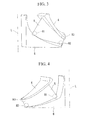
Fig. 7 }
Fig. 7 is a schematic diagram illustrating the structure of an impeller of a compressor according to a third embodiment of the present invention. - {
Fig. 8 }
Fig. 8 is a schematic diagram illustrating the structures of upstream and downstream parts of the impeller inFig. 7 . - A compressor according to a first embodiment of the present invention will be described below with reference to
Figs. 1 to 4 .
Fig. 1 is a schematic diagram illustrating, in outline, the structure of the compressor of this embodiment.
In this embodiment, the case where the compressor of the present invention is applied to a centrifugal compressor for pumping a process gas (fluid) in a chemical plant will be described, although the compressor is not limited to a centrifugal compressor and may instead be applied to a mixed flow compressor or a compressor used for another application; that is, the type of compressor is not particularly limited. - As shown in
Fig. 1 , the centrifugal compressor (compressor) 1 pumps a fluid taken in from the upstream side (upper side inFig. 1 ) to the downstream side (lateral direction inFig. 1 ).
As shown inFig. 1 , the centrifugal compressor 1 includes arotating shaft 2 and animpeller 3. - As shown in
Fig. 1 , therotating shaft 2 is a substantially cylindrical member supported rotatably about an axis of rotation L and transmits an externally transmitted torque to theimpeller 3. -
Fig. 2 is a schematic diagram illustrating the structures of upstream and downstream parts of the impeller inFig. 1 .
As shown inFigs. 1 and 2 , theimpeller 3 is rotated about the axis of rotation L by therotating shaft 2 and, as it is rotated, it takes in a fluid from the upstream side and discharges the fluid to the downstream side.
Theimpeller 3 includes anupstream part 3U and adownstream part 3L divided at a dividing surface (bonding surface) P1. - The dividing surface P1 is a surface extending in a direction substantially perpendicular to the axis of rotation L and is a surface at which the
impeller 3 is divided into theupstream part 3U and thedownstream part 3L and also at which theupstream part 3U and thedownstream part 3L are bonded. - As shown in
Figs. 1 and 2 , the dividing surface P1 may be a flat surface or a conical surface having the axis of rotation L as the axis thereof and is not particularly limited.
If the dividing surface P1 is a conical surface, the dividing surface P1 is inclined to such an extent that a melted bonding material used for theupstream part 3U and thedownstream part 3L does not flow downward when the axis of rotation L is oriented substantially vertically. - As shown in
Fig. 1 , theupstream part 3U is bonded to thedownstream part 3L at the dividing surface P1 to constitute theimpeller 3.
Theupstream part 3U includes anupstream shroud 4U andupstream blade segments 5U. - As shown in
Fig. 1 , theupstream shroud 4U is an upstream segment (upper segment inFig. 1 ) of ashroud 4 divided in two at the dividing surface P1 and is bonded to adownstream shroud 4L at the dividing surface P1 to constitute theshroud 4.
In addition, theupstream shroud 4U integrally constitutes theupstream part 3U, together with theupstream blade segments 5U. - As shown in
Fig. 1 , theshroud 4 is a cylindrical member whose diameter increases from the upstream to downstream sides or an angular plate-like member inclined toward ahub 6 so as to extend radially outward. In addition, theshroud 4 joins the tips of a plurality ofimpeller blades 5.
The shape of theshroud 4 may be a known shape and is not particularly limited. - As shown in
Fig. 1 , theupstream blade segments 5U are upstream segments of theimpeller blades 5 divided in two at the dividing surface P1 and are bonded todownstream blade segments 5L at the dividing surface P1 to constitute theimpeller blades 5. In addition, theupstream blade segments 5U integrally constitute theupstream part 3U, together with theupstream shroud 4U. - As shown in
Fig. 1 , theimpeller blades 5 are blades extending radially outward from the outer circumferential surface of thehub 6 and arranged at regular intervals circumferentially about the axis of rotation L.
The shape of theimpeller blades 5 may be a known shape and is not particularly limited. - As shown in
Fig. 1 , thedownstream part 3L is bonded to theupstream part 3U at the dividing surface P1 to constitute theimpeller 3.
Thedownstream part 3L includes thedownstream shroud 4L, thedownstream blade segments 5L, and thehub 6. - As shown in
Fig. 1 , thedownstream shroud 4L is the downstream segment (lower segment inFig. 1 ) of theshroud 4 divided in two at the dividing surface P1 and is bonded to theupstream shroud 4U at the dividing surface P1 to constitute theshroud 4.
In addition, thedownstream shroud 4L integrally constitutes thedownstream part 3L, together with thedownstream blade segments 5L and thehub 6. - As shown in
Fig. 1 , thedownstream blade segments 5L are the downstream segments of theimpeller blades 5 divided in two at the dividing surface P1 and are bonded to theupstream blade segments 5U at the dividing surface P1 to constitute theimpeller blades 5.
In addition, thedownstream blade segments 5L integrally constitute the downstream part, together with thedownstream shroud 4L and thehub 6. - As shown in
Fig. 1 , thehub 6 is rotatably supported by therotating shaft 2 and is formed in a substantially conical shape whose diameter increases from the upstream to downstream sides along a fluid flow. Theimpeller blades 5 are disposed on the outer circumferential surface of thehub 6 so as to extend radially outward. - Here, regions where a high stress occurs as the
impeller 3 is rotated will be described.
Figs. 3 and 4 are partial perspective views of the impeller, illustrating regions where a high stress occurs as the impeller is rotated. - As shown in
Figs. 3 and 4 , as theimpeller 3 is rotated, a high stress occurs in high-stress regions R1 near the upstream ends of the boundary regions between thedownstream blade segments 5L and thehub 6, high-stress regions R2 near the downstream ends thereof, and high-stress regions R3 near the downstream ends of the boundary regions between the downstream blade segments and the downstream shroud. - In this embodiment, as shown in
Figs. 1 and 2 , theimpeller 3 is divided into theupstream part 3U and thedownstream part 3L at the dividing surface P1. Accordingly, the above high-stress regions R1, R2, and R3 are associated with thedownstream part 3L, which is integrally formed. - Next, a method for producing the
impeller 3 of this embodiment will be described.
As shown inFig. 2 , first, theupstream part 3U and thedownstream part 3L of theimpeller 3 are separately formed (forming step).
The method used for forming theupstream part 3U and thedownstream part 3L may be a known method such as casting, machining, or electrical discharge machining and is not particularly limited. - Subsequently, as shown in
Fig. 1 , theupstream part 3U and thedownstream part 3L formed separately are bonded at the dividing surface P1, thus producing the impeller 3 (bonding step).
In this embodiment, the case where theupstream part 3U and thedownstream part 3L are bonded at the dividing surface P1 by diffusion bonding will be described. - To bond the
upstream part 3U and thedownstream part 3L, thedownstream shroud 4L is placed with the axis of rotation L substantially vertical, in other words, with the dividing surface P1 substantially horizontal, and a bonding material is then applied over the dividing surface P1.
Subsequently, as shown inFig. 1 , theupstream part 3U is placed on thedownstream part 3L, and diffusion bonding is performed by placing theupstream part 3U and thedownstream part 3L in a high-temperature environment such as the interior of a furnace. - The bonding at the dividing surface P1 may be diffusion bonding, as described above, or may be brazing or welding and is not particularly limited.
In addition, the diffusion bonding is not limited to solid-phase diffusion bonding and may instead be liquid-phase diffusion bonding. - Next, the operation of the centrifugal compressor 1 having the structure described above will be described.
In the centrifugal compressor 1, as shown inFig. 1 , theimpeller 3 is rotated by therotating shaft 2 to take a fluid from the upstream side (upper side inFig. 1 ) into the space between thehub 6 and theshroud 4, in other words, the space in which theimpeller blades 5 are disposed. - The intake fluid is then transferred to the downstream side (lateral direction in
Fig. 1 ) along the wall surfaces of thehub 6 and theshroud 4 by theimpeller blades 5. The transferred fluid is discharged from the centrifugal compressor 1 after the kinetic energy thereof is partially converted to pressure by diffusers (not shown) of the centrifugal compressor 1. - In the structure described above, because the
upstream part 3U integrally constituted by theupstream blade segments 5U and theupstream shroud 4U and thedownstream part 3L integrally constituted by thedownstream blade segments 5L, thedownstream shroud 4L, and thehub 6 are bonded at the dividing surface P1, theimpeller 3 has smaller unremoved portions than an impeller fabricated by machining using a machining tool. This inhibits disruption of the fluid flow through theimpeller 3, thus improving the performance of the centrifugal compressor 1. - That is, the
upstream part 3U and thedownstream part 3L have smaller unremoved portions than in the case where theentire impeller 3 is integrally formed because they interfere with a machining tool over a narrower region. Accordingly, theimpeller 3 having theupstream part 3U and thedownstream part 3L bonded at the dividing surface P1 has smaller unremoved portions. - In addition, because the
upstream blade segments 5U and theupstream shroud 4U are integrally formed and thedownstream blade segments 5L, thedownstream shroud 4L, and thehub 6 are integrally formed, sufficient strength is ensured in regions where a high stress occurs as theimpeller 3 is rotated. This prevents damage to theimpeller 3, thus improving the reliability of the centrifugal compressor 1. - Specifically, as the
impeller 3 is rotated, a high stress occurs in the high-stress regions R1 near the upstream ends of the boundary regions between thedownstream blade segments 5L and thehub 6, the high-stress regions R2 near the downstream ends thereof, and the high-stress regions R3 near the downstream ends of the boundary regions between thedownstream blade segments 5L and thedownstream shroud 4L. In these regions, sufficient strength can be ensured by integrally forming thedownstream blade segments 5L, thedownstream shroud 4L, and thehub 6, rather than bonding theimpeller blades 5 and theshroud 4, thus preventing damage to theimpeller 3. - Furthermore, because the
upstream part 3U and thedownstream part 3L can be fabricated with higher precision than in a method in which impeller blades and a shroud are bonded, theimpeller 3 having the two parts bonded and the centrifugal compressor 1 including theimpeller 3 can be fabricated with higher precision. This improves the reliability and performance of theimpeller 3 and the centrifugal compressor 1. - At the same time, because the
downstream part 3L is placed with the dividing surface P1 substantially horizontal before theupstream part 3U and thedownstream part 3L are bonded, a bonding failure can be prevented at the dividing surface.
Specifically, in this embodiment, which employs diffusion bonding, thedownstream part 3L is placed with the bonding surface, described above, substantially horizontal before theupstream part 3U and thedownstream part 3L are bonded, so that the bonding material used for bonding cannot easily flow downward. In other words, the bonding material is present substantially uniformly over the entire dividing surface P1, thus preventing a bonding failure due to insufficient bonding material. - Next, a second embodiment of the present invention will be described with reference to
Figs. 5 and 6 .
The basic structure of the compressor of this embodiment is similar to that of the first embodiment; however, they differ in the position of the dividing surface. In this embodiment, therefore, the structures of the dividing surface and the upstream and downstream parts will be described usingFigs. 5 and 6 , and a description of the other elements etc. will be omitted.
Fig. 5 is a schematic diagram illustrating the structure of the impeller of the compressor according to this embodiment.Fig. 6 is a schematic diagram illustrating the structures of the upstream and downstream parts of the impeller inFig. 5 .
The same elements as those in the first embodiment are denoted by the same reference signs, and a description thereof will be omitted. - As shown in
Figs. 5 and 6 , animpeller 13 of a centrifugal compressor (compressor) 11 of this embodiment includes anupstream part 13U and adownstream part 23L divided at a dividing surface (bonding surface) P2. - As shown in
Fig. 6 , theupstream part 13U is bonded to thedownstream part 13L at the dividing surface P2 to constitute theimpeller 13.
Theupstream part 13U includes ashroud 4 andupstream blade segments 5U. - As shown in
Fig. 6 , thedownstream part 13L is bonded to theupstream part 13U at the dividing surface P2 to constitute theimpeller 13.
Thedownstream part 13L includes thedownstream blade segments 5L and thehub 6. - Next, a method for producing the
impeller 13 of this embodiment will be described.
As shown inFig. 6 , first, theupstream part 13U and thedownstream part 13L of theimpeller 13 are separately formed (forming step).
The method used for forming theupstream part 13U and thedownstream part 13L may be a known method such as casting or machining and is not particularly limited. - Subsequently, as shown in
Fig. 5 , theupstream part 13U and thedownstream part 13L formed separately are bonded at the dividing surface P2, thus producing the impeller 13 (bonding step). - The bonding at the dividing surface P2 may be diffusion bonding, as described above, or may be brazing or welding and is not particularly limited.
In addition, the diffusion bonding is not limited to solid-phase diffusion bonding and may instead be liquid-phase diffusion bonding. - In the structure described above, because the
upstream part 13U integrally constituted by theupstream blade segments 5U and theshroud 4 and thedownstream part 13L integrally constituted by thedownstream blade segments 5L and thehub 6 are bonded at the dividing surface P2, theimpeller 13 has smaller unremoved portions than an impeller fabricated by machining using a machining tool. This inhibits disruption of the fluid flow through theimpeller 13, thus improving the performance of thecentrifugal compressor 11. - In addition, because the
upstream blade segments 5U and theshroud 4 are integrally formed and thedownstream blade segments 5L and thehub 6 are integrally formed, sufficient strength is ensured in regions where a high stress occurs as theimpeller 13 is rotated, thus preventing damage to theimpeller 13. - Specifically, as the
impeller 13 is rotated, a high stress occurs in the high-stress regions R3 near the downstream ends of the boundary regions between theupstream blade segments 5U and theshroud 4. In these regions, sufficient strength is ensured by integrally forming theupstream blade segments 5U and theshroud 4, rather than bonding theimpeller blades 5 and theshroud 4, thus preventing damage to theimpeller 13. - Similarly, as the
impeller 13 is rotated, a high stress occurs in the high-stress regions R1 near the upstream ends of the boundary regions between thedownstream blade segments 5L and thehub 6 and the high-stress regions R2 near the downstream ends thereof. In these regions, sufficient strength is ensured by integrally forming thedownstream blade segments 5L and thehub 6, rather than bonding theimpeller blades 5 and theshroud 4, thus preventing damage to theimpeller 13. - Next, a third embodiment of the present invention will be described with reference to
Figs. 7 and 8 .
The basic structure of the compressor of this embodiment is similar to that of the first embodiment; however, they differ in the position of the dividing surface. In this embodiment, therefore, the structures of the dividing surface and the upstream and downstream parts will be described usingFigs. 7 and 8 , and a description of the other elements etc. will be omitted.
Fig. 7 is a schematic diagram illustrating the structure of the impeller of the compressor according to this embodiment.Fig. 8 is a schematic diagram illustrating the structures of the upstream and downstream parts of the impeller inFig. 7 .
The same elements as those in the first embodiment are denoted by the same reference signs, and a description thereof will be omitted. - As shown in
Figs. 7 and 8 , animpeller 23 of a centrifugal compressor (compressor) 21 of this embodiment includes anupstream part 23U and adownstream part 23L divided at a dividing surface (bonding surface) P3. - As shown in
Fig. 8 , theupstream part 23U is bonded to thedownstream part 23L at the dividing surface P3 to constitute theimpeller 23.
Theupstream part 23U includes anupstream shroud 24U andupstream blade segments 25U. - As shown in
Fig. 8 , theupstream shroud 24U is the upstream segment (upper segment inFig. 8 ) of theshroud 4 divided in two at the dividing surface P3 and is bonded to adownstream shroud 24L at the dividing surface P3 to constitute theshroud 4. - As shown in
Fig. 8 , theupstream blade segments 25U are the upstream segments of theimpeller blades 5 divided in two at the dividing surface P3. Accordingly, theupstream blade segments 5U have portions bonded to thedownstream blade segments 25L and portions bonded to thehub 6.
In addition, theupstream blade segments 25U integrally constitute theupstream part 23U, together with theupstream shroud 24U. - As shown in
Fig. 8 , thedownstream part 23L is bonded to theupstream part 23U at the dividing surface P3 to constitute theimpeller 23.
Thedownstream part 23L includes thedownstream shroud 24L, thedownstream blade segments 25L, and thehub 6. - As shown in
Fig. 8 , thedownstream shroud 24L is the downstream segment (lower segment inFig. 8 ) of theshroud 4 divided in two at the dividing surface P3 and is bonded to theupstream shroud 24U at the dividing surface P3 to constitute theshroud 4. - As shown in
Fig. 8 , thedownstream blade segments 25L are the downstream segments of theimpeller blades 5 divided in two at the dividing surface P3 and are bonded to theupstream blade segments 25U at the dividing surface P3 to constitute theimpeller blades 5.
In addition, thedownstream blade segments 25L integrally constitute thedownstream part 23U, together with thedownstream shroud 24L and thehub 6. - As shown in
Fig. 7 , the dividing surface P3 is a surface constituted by a portion extending in a direction substantially perpendicular to the axis of rotation L and dividing theimpeller 3 and theshroud 4 and a portion extending radially inward so as to be inclined upward (upward inFig. 7 ) along the bonding surface between thehub 6 and theimpeller 3.
In other words, the dividing surface P1 is also the surface at which theupstream part 23U and thedownstream part 23L are bonded. - Next, a method for producing the
impeller 23 of this embodiment will be described.
As shown inFig. 8 , first, theupstream part 23U and thedownstream part 23L of theimpeller 23 are separately formed (forming step).
The method used for forming theupstream part 23U and thedownstream part 23L may be a known method such as casting, machining, or electrical discharge machining and is not particularly limited. - Subsequently, as shown in
Fig. 7 , theupstream part 23U and thedownstream part 23L formed separately are bonded at the dividing surface P3, thus producing the impeller 23 (bonding step). - Specifically, the bonding is performed by brazing in the portion of the dividing surface P3 where the
upstream blade segments 23U and thedownstream blade segments 25L are bonded.
In other words, theupstream part 23U and thedownstream part 23L are bonded by brazing in the substantially horizontal portion of the dividing surface P3, that is, the portion of the dividing surface P3 substantially perpendicular to the axis of rotation L. - On the other hand, the bonding is performed by welding in the portion of the dividing surface P3 where the
upstream blade segments 25U and thehub 6 are bonded.
In other words, theupstream part 23U and thedownstream part 23L are bonded by welding in the inclined portion of the dividing surface P1. - In the structure described above, the
hub 6, which is integrally formed, has a higher strength than asegmented hub 6.
It is preferable that thehub 6 have a higher strength because force acts thereon as the centrifugal compressor 1 is operated. - Because the
upstream part 23U and thedownstream part 23L are bonded by brazing in the portion of the dividing surface P3 extending substantially horizontally, the brazing alloy can be prevented from leaking out, thus allowing stable bonding. - On the other hand, because the bonding is performed by welding in the inclined portion of the dividing surface P3, a bonding failure due to leakage of a brazing alloy can be prevented. In addition, because the welded joint is limited by providing the brazed joint, which permits high bonding precision, the
upstream part 23U and thedownstream part 23L can be bonded with high precision. -
- 1, 11, 21
- centrifugal compressor (compressor)
- 3, 13, 23
- impeller
- 3U, 13U, 23U
- upstream part
- 3L, 13L, 23L
- downstream part
- 4
- shroud
- 4U, 24U
- upstream shroud
- 4L, 24L
- downstream shroud
- 5
- impeller blade
- 5U, 25U
- upstream blade segment
- 5L, 25L
- downstream blade segment
- 6
- hub
- P1, P2, P3
- dividing surface (bonding surface)
- L
- axis of rotation
Claims (5)
- An impeller comprising:a hub which is supported rotatably about an axis of rotation and whose diameter increases from upstream to downstream sides along a fluid flow;a plurality of impeller blades extending radially outward from an outer circumferential surface of the hub; anda shroud formed in a cylindrical shape whose diameter increases from the upstream to downstream sides along the fluid flow and joining outer circumferential ends of the plurality of impeller blades;wherein the impeller blades comprise upstream blade segments and downstream blade segments bonded at a bonding surface extending in a direction substantially perpendicular to the axis of rotation; andwherein the upstream blade segments are integral with at least a portion of the shroud, and the downstream blade segments are integral with at least a portion of the hub.
- The impeller according to Claim 1, wherein the shroud comprises an upstream shroud and a downstream shroud bonded at the bonding surface; and
wherein the upstream blade segments are formed integrally with the upstream shroud, and the downstream blade segments are formed integrally with the downstream shroud and the hub. - The impeller according to Claim 1, wherein the upstream blade segments are formed integrally with the shroud, and the downstream blade segments are formed integrally with the hub.
- A compressor comprising the impeller according to one of Claims 1 to 3.
- A method for producing an impeller, comprising:a forming step of forming:an upstream part including upstream blade segments, disposed upstream along a fluid flow, of impeller blades divided at a dividing surface extending in a direction substantially perpendicular to an axis of rotation of a hub and at least a portion of a shroud; anda downstream part including downstream blade segments, disposed downstream, of the impeller blades divided at the dividing surface and at least a portion of the hub; anda bonding step of placing the downstream part with the dividing surface substantially horizontal and bonding the upstream part and the downstream part at the dividing surface.
Applications Claiming Priority (2)
| Application Number | Priority Date | Filing Date | Title |
|---|---|---|---|
| JP2009025944A JP2010121612A (en) | 2008-10-23 | 2009-02-06 | Impeller, compressor, and method of manufacturing the impeller |
| PCT/JP2010/050401 WO2010090062A1 (en) | 2009-02-06 | 2010-01-15 | Impeller, compressor, and impeller fabrication method |
Publications (2)
| Publication Number | Publication Date |
|---|---|
| EP2395246A1 true EP2395246A1 (en) | 2011-12-14 |
| EP2395246A4 EP2395246A4 (en) | 2018-01-24 |
Family
ID=42542730
Family Applications (1)
| Application Number | Title | Priority Date | Filing Date |
|---|---|---|---|
| EP10738401.8A Withdrawn EP2395246A4 (en) | 2009-02-06 | 2010-01-15 | Impeller, compressor, and impeller fabrication method |
Country Status (3)
| Country | Link |
|---|---|
| EP (1) | EP2395246A4 (en) |
| CN (1) | CN102203428B (en) |
| WO (1) | WO2010090062A1 (en) |
Cited By (4)
| Publication number | Priority date | Publication date | Assignee | Title |
|---|---|---|---|---|
| EP2669042A1 (en) * | 2012-05-30 | 2013-12-04 | Sulzer Markets and Technology AG | Method for producing a workpiece using a cutting device |
| US20140193268A1 (en) * | 2013-01-09 | 2014-07-10 | Fanuc Corporation | Method of formation of impeller with shape defined by plurality of lines and such impeller |
| US11022135B2 (en) | 2019-02-26 | 2021-06-01 | Mitsubishi Heavy Industries Compressor Corporation | Impeller and rotating machine |
| US11162505B2 (en) | 2013-12-17 | 2021-11-02 | Nuovo Pignone Srl | Impeller with protection elements and centrifugal compressor |
Families Citing this family (7)
| Publication number | Priority date | Publication date | Assignee | Title |
|---|---|---|---|---|
| JP5998544B2 (en) * | 2012-03-13 | 2016-09-28 | アイシン精機株式会社 | Impeller manufacturing method and impeller |
| KR101960714B1 (en) * | 2012-11-30 | 2019-03-22 | 한화파워시스템 주식회사 | Impeller |
| CN105849418B (en) * | 2013-12-27 | 2018-11-13 | 本田技研工业株式会社 | impeller |
| CN105090104A (en) * | 2015-06-25 | 2015-11-25 | 海信(山东)空调有限公司 | Air conditioner outdoor unit with inclined centrifugal fan and air conditioner |
| CN107989823B (en) * | 2017-12-26 | 2023-12-01 | 北京伯肯节能科技股份有限公司 | Impeller, centrifugal compressor and fuel cell system |
| US11473592B2 (en) * | 2019-08-13 | 2022-10-18 | Emerson Climate Technologies, Inc. | Systems and methods for manufacturing a shrouded impeller |
| JP6982267B2 (en) * | 2020-05-08 | 2021-12-17 | ダイキン工業株式会社 | Closed impeller and manufacturing method of closed impeller |
Family Cites Families (8)
| Publication number | Priority date | Publication date | Assignee | Title |
|---|---|---|---|---|
| DE462853C (en) * | 1927-11-05 | 1928-07-19 | Lorenzen G M B H C | Runner for centrifugal compressor, the cover disk of which is pressed in the axial direction against the free edges of the blades machined from one piece with the runner disk |
| DE755198C (en) * | 1935-12-20 | 1952-11-24 | Versuchsanstalt Fuer Luftfahrt | Centrifugal machine impeller for high peripheral speeds |
| FR1022176A (en) * | 1950-07-19 | 1953-03-02 | Paddle wheel and its manufacturing process | |
| JP3291827B2 (en) * | 1993-03-18 | 2002-06-17 | 株式会社日立製作所 | Impeller, diffuser, and method of manufacturing the same |
| JP2004036444A (en) | 2002-07-02 | 2004-02-05 | Ishikawajima Harima Heavy Ind Co Ltd | Method for manufacturing impeller with shroud |
| JP4428044B2 (en) * | 2003-03-24 | 2010-03-10 | 株式会社日立プラントテクノロジー | Impeller manufacturing method and impeller |
| JP2005146962A (en) * | 2003-11-14 | 2005-06-09 | Hitachi Industries Co Ltd | Centrifugal impeller and manufacturing method thereof |
| EP2064440A1 (en) * | 2006-09-22 | 2009-06-03 | Voith Siemens Hydro Power Generation GmbH & Co. KG | Method for producing the rotor of a water turbine, and rotor |
-
2010
- 2010-01-15 WO PCT/JP2010/050401 patent/WO2010090062A1/en not_active Ceased
- 2010-01-15 CN CN201080003067.0A patent/CN102203428B/en not_active Expired - Fee Related
- 2010-01-15 EP EP10738401.8A patent/EP2395246A4/en not_active Withdrawn
Non-Patent Citations (1)
| Title |
|---|
| See references of WO2010090062A1 * |
Cited By (5)
| Publication number | Priority date | Publication date | Assignee | Title |
|---|---|---|---|---|
| EP2669042A1 (en) * | 2012-05-30 | 2013-12-04 | Sulzer Markets and Technology AG | Method for producing a workpiece using a cutting device |
| US20140193268A1 (en) * | 2013-01-09 | 2014-07-10 | Fanuc Corporation | Method of formation of impeller with shape defined by plurality of lines and such impeller |
| US9416664B2 (en) * | 2013-01-09 | 2016-08-16 | Fanuc Corporation | Method of formation of impeller with shape defined by plurality of lines and such impeller |
| US11162505B2 (en) | 2013-12-17 | 2021-11-02 | Nuovo Pignone Srl | Impeller with protection elements and centrifugal compressor |
| US11022135B2 (en) | 2019-02-26 | 2021-06-01 | Mitsubishi Heavy Industries Compressor Corporation | Impeller and rotating machine |
Also Published As
| Publication number | Publication date |
|---|---|
| WO2010090062A1 (en) | 2010-08-12 |
| CN102203428B (en) | 2015-11-25 |
| CN102203428A (en) | 2011-09-28 |
| EP2395246A4 (en) | 2018-01-24 |
Similar Documents
| Publication | Publication Date | Title |
|---|---|---|
| US8899931B2 (en) | Impeller, compressor, and method for producing impeller | |
| CN102203428B (en) | The manufacture method of impeller, compressor and impeller | |
| US8435005B2 (en) | Manufacturing method of impeller | |
| US9133855B2 (en) | Rotor for a turbo machine | |
| US20180202451A1 (en) | Centrifugal compressor | |
| EP2509739B1 (en) | Method of beam welding of an impeller with performance of two passes on a slot ; impeller and turbo machine having such weld configuration | |
| CN103195505B (en) | For aiming at the apparatus and method of top shroud | |
| JP4628865B2 (en) | Gas turbine blade, gas turbine using the same, and power plant | |
| US10030526B2 (en) | Platform core feed for a multi-wall blade | |
| CN103422992A (en) | Method for manufacturing a hot gas path component | |
| KR101960714B1 (en) | Impeller | |
| JP6388772B2 (en) | Centrifugal compressor and diffuser manufacturing method | |
| CN101845970A (en) | Turbomachine rotor assembly and method | |
| JP2009275513A (en) | Impeller, compressor using impeller and method for manufacturing impeller | |
| EP3171089B1 (en) | Cylinder of combustor, method of manufacturing of cylinder of combustor, and pressure vessel | |
| EP2276912B1 (en) | Rotary machine | |
| US20190071973A1 (en) | Rotating body and turbocharger | |
| KR101612854B1 (en) | Impeller assembly of fluid rotary machine | |
| KR20150088641A (en) | Impeller and manufacturing method the same | |
| KR20130117142A (en) | Impeller and manufacturing method thereof | |
| JP2004028002A (en) | Joint structure |
Legal Events
| Date | Code | Title | Description |
|---|---|---|---|
| PUAI | Public reference made under article 153(3) epc to a published international application that has entered the european phase |
Free format text: ORIGINAL CODE: 0009012 |
|
| 17P | Request for examination filed |
Effective date: 20110406 |
|
| AK | Designated contracting states |
Kind code of ref document: A1 Designated state(s): AT BE BG CH CY CZ DE DK EE ES FI FR GB GR HR HU IE IS IT LI LT LU LV MC MK MT NL NO PL PT RO SE SI SK SM TR |
|
| DAX | Request for extension of the european patent (deleted) | ||
| RA4 | Supplementary search report drawn up and despatched (corrected) |
Effective date: 20180104 |
|
| RIC1 | Information provided on ipc code assigned before grant |
Ipc: F04D 29/30 20060101ALI20171221BHEP Ipc: F04D 29/28 20060101AFI20171221BHEP |
|
| STAA | Information on the status of an ep patent application or granted ep patent |
Free format text: STATUS: THE APPLICATION HAS BEEN WITHDRAWN |
|
| 18W | Application withdrawn |
Effective date: 20180424 |