EP2395237A2 - Horizontal axis wind turbine - Google Patents
Horizontal axis wind turbine Download PDFInfo
- Publication number
- EP2395237A2 EP2395237A2 EP11168377A EP11168377A EP2395237A2 EP 2395237 A2 EP2395237 A2 EP 2395237A2 EP 11168377 A EP11168377 A EP 11168377A EP 11168377 A EP11168377 A EP 11168377A EP 2395237 A2 EP2395237 A2 EP 2395237A2
- Authority
- EP
- European Patent Office
- Prior art keywords
- motors
- wind turbine
- yaw
- rotation
- tower
- Prior art date
- Legal status (The legal status is an assumption and is not a legal conclusion. Google has not performed a legal analysis and makes no representation as to the accuracy of the status listed.)
- Granted
Links
- 238000010276 construction Methods 0.000 description 3
- 238000010586 diagram Methods 0.000 description 3
- 238000007664 blowing Methods 0.000 description 2
- 230000000052 comparative effect Effects 0.000 description 1
- 230000003111 delayed effect Effects 0.000 description 1
- 230000000694 effects Effects 0.000 description 1
- 238000005516 engineering process Methods 0.000 description 1
- 230000002265 prevention Effects 0.000 description 1
Images


Classifications
-
- F—MECHANICAL ENGINEERING; LIGHTING; HEATING; WEAPONS; BLASTING
- F03—MACHINES OR ENGINES FOR LIQUIDS; WIND, SPRING, OR WEIGHT MOTORS; PRODUCING MECHANICAL POWER OR A REACTIVE PROPULSIVE THRUST, NOT OTHERWISE PROVIDED FOR
- F03D—WIND MOTORS
- F03D7/00—Controlling wind motors
- F03D7/02—Controlling wind motors the wind motors having rotation axis substantially parallel to the air flow entering the rotor
- F03D7/0204—Controlling wind motors the wind motors having rotation axis substantially parallel to the air flow entering the rotor for orientation in relation to wind direction
-
- F—MECHANICAL ENGINEERING; LIGHTING; HEATING; WEAPONS; BLASTING
- F05—INDEXING SCHEMES RELATING TO ENGINES OR PUMPS IN VARIOUS SUBCLASSES OF CLASSES F01-F04
- F05B—INDEXING SCHEME RELATING TO WIND, SPRING, WEIGHT, INERTIA OR LIKE MOTORS, TO MACHINES OR ENGINES FOR LIQUIDS COVERED BY SUBCLASSES F03B, F03D AND F03G
- F05B2260/00—Function
- F05B2260/40—Transmission of power
- F05B2260/403—Transmission of power through the shape of the drive components
- F05B2260/4031—Transmission of power through the shape of the drive components as in toothed gearing
-
- F—MECHANICAL ENGINEERING; LIGHTING; HEATING; WEAPONS; BLASTING
- F05—INDEXING SCHEMES RELATING TO ENGINES OR PUMPS IN VARIOUS SUBCLASSES OF CLASSES F01-F04
- F05B—INDEXING SCHEME RELATING TO WIND, SPRING, WEIGHT, INERTIA OR LIKE MOTORS, TO MACHINES OR ENGINES FOR LIQUIDS COVERED BY SUBCLASSES F03B, F03D AND F03G
- F05B2260/00—Function
- F05B2260/50—Kinematic linkage, i.e. transmission of position
- F05B2260/507—Kinematic linkage, i.e. transmission of position using servos, independent actuators, etc.
-
- Y—GENERAL TAGGING OF NEW TECHNOLOGICAL DEVELOPMENTS; GENERAL TAGGING OF CROSS-SECTIONAL TECHNOLOGIES SPANNING OVER SEVERAL SECTIONS OF THE IPC; TECHNICAL SUBJECTS COVERED BY FORMER USPC CROSS-REFERENCE ART COLLECTIONS [XRACs] AND DIGESTS
- Y02—TECHNOLOGIES OR APPLICATIONS FOR MITIGATION OR ADAPTATION AGAINST CLIMATE CHANGE
- Y02E—REDUCTION OF GREENHOUSE GAS [GHG] EMISSIONS, RELATED TO ENERGY GENERATION, TRANSMISSION OR DISTRIBUTION
- Y02E10/00—Energy generation through renewable energy sources
- Y02E10/70—Wind energy
- Y02E10/72—Wind turbines with rotation axis in wind direction
Definitions
- the present invention relates to gear backlash prevention in a yaw rotation mechanism of a horizontal-axis wind turbine.
- a horizontal axis wind turbine comprises a rotor to which one, two or more blades are attached radially from a hub, a nacelle which rotatably supports the rotor by means of supporting a main shaft of the rotor which extends in the horizon and to which the hub is fixed, and a tower that supports the nacelle such that there is a free yaw rotation.
- a typical yaw rotation drive mechanism there is a drive mechanism in which the top section of the tower and the nacelle are linked by a yaw bearing having a yaw axis as the axis of rotation, an inner-teeth ring gear is attached to the inner race that is fastened on the tower side of the yaw bearing, a yaw motor is located on the nacelle, a pinion gear that is fastened to the drive shaft of the yaw motor engages with the ring gear, and by driving and rotating the yaw motor, the nacelle is rotated around the yaw axis.
- the yaw angle of the nacelle is controlled so that the nacelle, and thus the rotor faces in a desired direction such as the direction of the incoming wind (for example, refer to Japanese Patent Application Publication JP-A-2001-289 149 ).
- Swinging motion of the nacelle occurs due to backlash in the ring gear on the tower side and yaw gear on the nacelle side. Swinging motion of the nacelle could be a cause of damage to the yaw gear, yaw motor, rotor and the like.
- an object of the present invention is to provide a horizontal axis wind turbine that is capable of preventing gear backlash in a yaw rotation mechanism by driving and controlling a plurality of yaw motors.
- a horizontal axis wind turbine wherein the drive mechanism further comprises a plurality of brakes, each provided on a respective motor, for holding a drive shaft of each of the motors from rotating, and wherein the controller is connected to each of the brakes, and controls the brakes so that the drive shafts of the some of the motors are held from rotating when the some of the motors are stopped, and the drive shafts of the rest of the motors are held from rotating when the rest of the motors are stopped.
- a horizontal axis wind turbine apparatus wherein the controller, after stopping the rest of the motors, controls the plurality of motors so that each pinion gear of the some of the motors presses the ring gear toward one direction of rotation of the main wind turbine unit, and each pinion gear of the rest of the motors presses the ring gear toward the other direction of rotation of the main wind turbine unit.
- the horizontal axis wind turbine of the present invention as in the case of a conventional horizontal-axis wind turbine, has a rotor 8 to which one or two or more blades 8a are radially attached on the hub 8b, a nacelle 5 which rotatably supports the rotor 8 by means of supporting a main shaft 8c of the rotor 8 which extends in the horizontal direction and to which the hub 8b is fixed, and a tower 6 that supports the nacelle 5 so that there is a free yaw rotation between the nacelle 5 and the tower 6.
- the nacelle 5 and tower 6 are linked by way of a yaw bearing unit 1.
- the yaw bearing unit 1 comprises a bearing 1a, and an inner race 1b and outer race 1c for supporting the bearing 1a.
- the axis of rotation of the yaw bearing unit 1 is the yaw axis of the nacelle 5, and an internal-teeth ring gear 2 is fastened on the inside of the inner race 1b coaxially with the yaw axis.
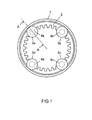
- FIG. 1 there are four yaw motors 3a, 3b, 3c and 3d in the horizontal axis wind turbine.
- a vertical cross-sectional view of the construction of yaw motor 3a is illustrated in FIG. 2 as a representative motor.
- the four yaw motors 3a, 3b, 3c and 3d all have the same construction.
- the frames of the four yaw motors 3a, 3b, 3c and 3d are fastened to locations in the nacelle 5.
- a pinion gear 4a (4b, 4c, 4d) which is the driving gear of the yaw motor 3a (3b, 3c, 3d), engages with the ring gear 2.
- a reduction gear 7 is mounted between the yaw motor 3a (3b, 3c, 3d) and the pinion gear 4a (4b, 4c, 4d).
- yaw rotation of the nacelle 5 can be performed.
- Yaw motor brakes are mounted in the yaw motors 3a, 3b, 3c and 3d.
- the case of driving yaw rotation of the nacelle using two yaw motors will be explained while referencing FIGS. 3A to 3C and FIGS. 4A to 4D .
- the ring gear 2 is drawn linearly, and teeth other than the teeth of the pinion gears 4m, 4n of the two yaw motors are omitted from the drawing.
- this space is the fluctuating width, and the ring gear 2 fluctuates back and forth relative to the pinion gears 4m, 4n due to external disturbance.
- backlash occurs.
- swinging motion of the nacelle occurs due to the gear backlash in the yaw rotation mechanism, and thus there is a possibility that the gears, yaw motors, rotor and the like could be damaged.
- Control for stopping yaw rotation of the nacelle of this embodiment is performed as described below.
- the tooth surface 4m1 of the pinion gear 4m and the tooth surface 4n1 of the pinion gear 4n that is in the opposite direction in the direction of rotation of the ring gear 2 from the tooth surface 4m1 are pressed to the teeth of ring gear 2 as illustrated in FIG. 4D , and the ring gear 2 is held. That is, the ring gear 2 receives the loads from the pinion gear 4m and pinion gear 4n that are in the opposite direction from each other and is held. As a result, backlash is prevented.
- Control for stopping yaw rotation of the nacelle 5 that was explained above with reference to FIGS. 4A to 4D is applied to the four yaw motors 3a, 3b, 3c and 3d illustrated in FIG. 1 .
- Yaw motor 3a and 3c are stopped first, after which yaw motors 3b and 3d are stopped, or yaw motors 3a and 3b are stopped first, after which yaw motors 3c and 3d are stopped. In doing so, backlash is prevented.
- the number of yaw motors that are stopped first will be the same as the number of yaw motors stopped later.
- the difference in the number of the yaw motors stopped first and the number of yaw motors stopped later will be one. This is in order to increase the holding force.
- the yaw motors 3a to 3d were fastened to the nacelle 5, and the gear (ring gear 2) that engages with the drive gears (pinion gears 4) of the yaw motors 3a to 3d are fastened to the tower 6, however, it is also possible to fasten the yaw motors 3a to 3d to the tower 6 and to fasten the gear 2that engages with the drive gears of the yaw motors 3a to 3d to the nacelle 5.
- the latter construction can be achieved by fastening the inner race 1b of the yaw bearing 1 to the nacelle 5, and fastening the outer race 1c to the tower 6.
Landscapes
- Engineering & Computer Science (AREA)
- Life Sciences & Earth Sciences (AREA)
- Sustainable Development (AREA)
- Sustainable Energy (AREA)
- Chemical & Material Sciences (AREA)
- Combustion & Propulsion (AREA)
- Mechanical Engineering (AREA)
- General Engineering & Computer Science (AREA)
- Wind Motors (AREA)
Abstract
Description
- The present invention relates to gear backlash prevention in a yaw rotation mechanism of a horizontal-axis wind turbine.
- Typically, a horizontal axis wind turbine comprises a rotor to which one, two or more blades are attached radially from a hub, a nacelle which rotatably supports the rotor by means of supporting a main shaft of the rotor which extends in the horizon and to which the hub is fixed, and a tower that supports the nacelle such that there is a free yaw rotation.
- As a typical yaw rotation drive mechanism there is a drive mechanism in which the top section of the tower and the nacelle are linked by a yaw bearing having a yaw axis as the axis of rotation, an inner-teeth ring gear is attached to the inner race that is fastened on the tower side of the yaw bearing, a yaw motor is located on the nacelle, a pinion gear that is fastened to the drive shaft of the yaw motor engages with the ring gear, and by driving and rotating the yaw motor, the nacelle is rotated around the yaw axis.
- With this mechanism, the yaw angle of the nacelle is controlled so that the nacelle, and thus the rotor faces in a desired direction such as the direction of the incoming wind (for example, refer to Japanese Patent Application Publication
JP-A-2001-289 149 - Not only does the wind speed change with respect to the wind turbine, but also turbulence such as sudden crosswinds, blowing upward from underneath, or blowing downward from above occurs. These have a large effect on the operation of the wind turbine.
- When turbulent wind occurs, swinging motion of the nacelle occurs due to backlash in the ring gear on the tower side and yaw gear on the nacelle side. Swinging motion of the nacelle could be a cause of damage to the yaw gear, yaw motor, rotor and the like.
- Taking into consideration the related technology described above, an object of the present invention is to provide a horizontal axis wind turbine that is capable of preventing gear backlash in a yaw rotation mechanism by driving and controlling a plurality of yaw motors.
- According to a first embodiment of the present invention for achieving the purpose described above, there is provided
- a horizontal axis wind turbine, comprising:
- a main wind turbine unit;
- a tower holding the main wind turbine unit rotatably in a substantially horizontal direction; and
- a drive mechanism located between the main wind turbine unit and the tower, configured to rotate the main wind turbine unit relative to the tower in the horizontal direction,
- wherein the drive mechanism, comprises:
- a ring gear fixed to one of the tower and the main wind turbine unit;
- a plurality of pinion gears for engaging with the ring gear;
- a plurality of motors, each of the motors being fixed to a respective pinion gear, configured to rotate the main wind turbine unit relative to the tower by driving the pinion gears, said plurality of motors being fixed to the other of the tower and main wind turbine unit; and
- a controller connected to each of the motors, for controlling the motors,
- wherein the controller, when stopping a rotation of the main wind turbine unit, stops some of the motors, and then stops the rest of the motors after a specified amount of time.
- According to a second embodiment of the present invention for achieving the purpose above, there is provided a horizontal axis wind turbine, wherein the drive mechanism further comprises a plurality of brakes, each provided on a respective motor, for holding a drive shaft of each of the motors from rotating, and wherein the controller is connected to each of the brakes, and controls the brakes so that the drive shafts of the some of the motors are held from rotating when the some of the motors are stopped, and the drive shafts of the rest of the motors are held from rotating when the rest of the motors are stopped.
- According to a third embodiment of the present invention for achieving the purpose described above, there is provided a horizontal axis wind turbine apparatus
wherein the controller, after stopping the rest of the motors, controls the plurality of motors so that each pinion gear of the some of the motors presses the ring gear toward one direction of rotation of the main wind turbine unit, and each pinion gear of the rest of the motors presses the ring gear toward the other direction of rotation of the main wind turbine unit. - With the present invention, when driving the nacelle in the yaw direction using a plurality of yaw motors, and rotation is stopped, firstly some of the yaw motors are stopped, and then after a delay the remaining yaw motors are stopped.
- Therefore, teeth surfaces on opposite sides from each other of the pinion gears of some of the yaw motors and the pinion gears of the other yaw motors come in contact with a common gear, and spaces between teeth, which are caused by backlash, are eliminated. As a result, gear backlash in the yaw rotation mechanism can be prevented.
- Other features and advantages of the present invention will become apparent from the following detailed description, taken in conjunction with the accompanying drawings, which illustrate, by way of example, the principles of the invention.
-
- FIG. 1
- is a top view of the linkage unit between the tower and nacelle of a horizontal axis wind turbine of an embodiment of the present invention.
- FIG. 2
- is a cross-sectional drawing of section A-A in
FIG. 1 . - FIGS. 3A to 3C
- are schematic diagrams of the operating state and illustrate the operation when stopping yaw rotation of the nacelle of a comparative example.
- FIGS. 4A to 4D
- are schematic diagrams of the operating state, and illustrate the operation when stopping yaw rotation of the nacelle of an embodiment of the present invention.
- FIGS. 5A and 5B
- are schematic diagrams of the horizontal axis wind turbine of the embodiment of the present invention.
- FIG. 6
- is a cross-sectional drawing of section B-B in
FIG. 5A . - In the following, an embodiment of the present invention is explained with reference to the accompanying drawings. The following is one embodiment of the present invention and does not limit the invention.
- The horizontal axis wind turbine of the present invention, as in the case of a conventional horizontal-axis wind turbine, has a rotor 8 to which one or two or
more blades 8a are radially attached on thehub 8b, anacelle 5 which rotatably supports the rotor 8 by means of supporting amain shaft 8c of the rotor 8 which extends in the horizontal direction and to which thehub 8b is fixed, and atower 6 that supports thenacelle 5 so that there is a free yaw rotation between thenacelle 5 and thetower 6. - As illustrated in
FIG. 1 andFIG. 2 , in the horizontal axis wind turbine of this embodiment, in order to support thenacelle 5 by the top section of thetower 6 such thatnacelle 5 has the free yaw rotation, thenacelle 5 andtower 6 are linked by way of a yaw bearingunit 1. - As illustrated in
FIG. 2 , theyaw bearing unit 1 comprises abearing 1a, and aninner race 1b andouter race 1c for supporting thebearing 1a. - By fastening the
inner race 1b to thetower 6 and fastening theouter race 1c to thenacelle 5, thetower 6 andnacelle 5 are linked so that there is said free rotation. The axis of rotation of theyaw bearing unit 1 is the yaw axis of thenacelle 5, and an internal-teeth ring gear 2 is fastened on the inside of theinner race 1b coaxially with the yaw axis. - As illustrated in
FIG. 1 , there are fouryaw motors yaw motor 3a is illustrated inFIG. 2 as a representative motor. The fouryaw motors - In other words, the frames of the four
yaw motors nacelle 5. As illustrated inFIG. 2 , apinion gear 4a (4b, 4c, 4d), which is the driving gear of theyaw motor 3a (3b, 3c, 3d), engages with thering gear 2. Areduction gear 7 is mounted between theyaw motor 3a (3b, 3c, 3d) and thepinion gear 4a (4b, 4c, 4d). - By rotating and driving the
yaw motors nacelle 5 can be performed. - Yaw motor brakes are mounted in the
yaw motors FIGS. 3A to 3C andFIGS. 4A to 4D . InFIGS. 3A to 3C andFIGS. 4A to 4D , in order to simplify the explanation, thering gear 2 is drawn linearly, and teeth other than the teeth of the pinion gears 4m, 4n of the two yaw motors are omitted from the drawing. - As illustrated in
FIG. 3A , while two pinion gears 4m, 4n are simultaneously rotated and driven by the respective yaw motors, and the rotation of these two yaw motors, and thus the rotation of the pinion gears 4m, 4n is simultaneously stopped and held so as not to rotate by the yaw motor brakes, as illustrated inFIG. 3B , rotation is stopped with the pinion gears 4m, 4n contacting with the tooth surfaces in the same direction of thering gear 2. - On the opposite sides from the contact surfaces of the teeth, a space occurs between the teeth, which becomes the cause of backlash.
- Therefore, as illustrated in
FIG. 3C , this space is the fluctuating width, and thering gear 2 fluctuates back and forth relative to the pinion gears 4m, 4n due to external disturbance. In other words, backlash occurs. In this case, swinging motion of the nacelle occurs due to the gear backlash in the yaw rotation mechanism, and thus there is a possibility that the gears, yaw motors, rotor and the like could be damaged. - Control for stopping yaw rotation of the nacelle of this embodiment is performed as described below.
- As illustrated in
FIG. 4A , while the two pinion gears 4m, 4n are simultaneously being rotated and driven by the yaw motors, first the rotation of one of the yaw motors is stopped, or in other words, the rotation of thepinion gear 4m is stopped, and rotation is prevented by the yaw brake (seeFIG. 4B ). - At this instant, rotating and driving the other yaw motor, or in other words, rotating and driving the
pinion gear 4n continues. Therefore, as time elapses, the tooth of thering gear 2 which is rotated by the power from thepinion gear 4n comes into contact with the stoppedpinion gear 4m. - Being delayed from the point in time when rotation of the one yaw motor is stopped, at the time when both the
pinion gear 4m andpinion gear 4n press the teeth of thering gear 2, rotation of the other yaw motor, in other words, rotation of thepinion gear 4n is stopped, and rotation of thepinion gear 4n is prevented by the yaw motor brake (FIG. 4D ). - As a result of the above, the tooth surface 4m1 of the
pinion gear 4m and the tooth surface 4n1 of thepinion gear 4n that is in the opposite direction in the direction of rotation of thering gear 2 from the tooth surface 4m1 are pressed to the teeth ofring gear 2 as illustrated inFIG. 4D , and thering gear 2 is held. That is, thering gear 2 receives the loads from thepinion gear 4m andpinion gear 4n that are in the opposite direction from each other and is held. As a result, backlash is prevented. - Control for stopping yaw rotation of the
nacelle 5 that was explained above with reference toFIGS. 4A to 4D is applied to the fouryaw motors FIG. 1 .Yaw motor yaw motors yaw motors motors - Therefore, damage to the
ring gear 2, yaw motor 3, pinion gear 4,reduction gear 7, rotor and the like caused by backlash is prevented. When there is an even number of yaw motors, preferably the number of yaw motors that are stopped first will be the same as the number of yaw motors stopped later. When there is an odd number of yaw motors, preferably the difference in the number of the yaw motors stopped first and the number of yaw motors stopped later will be one. This is in order to increase the holding force. - In the embodiment described above, the
yaw motors 3a to 3d were fastened to thenacelle 5, and the gear (ring gear 2) that engages with the drive gears (pinion gears 4) of theyaw motors 3a to 3d are fastened to thetower 6, however, it is also possible to fasten theyaw motors 3a to 3d to thetower 6 and to fasten the gear 2that engages with the drive gears of theyaw motors 3a to 3d to thenacelle 5. The latter construction can be achieved by fastening theinner race 1b of theyaw bearing 1 to thenacelle 5, and fastening theouter race 1c to thetower 6. - It is to be understood that the above-described embodiments are illustrative of only a few of the many possible specific embodiments which can represent applications of the principles of the invention. Numerous and varied other arrangements can be readily devised by those skilled in the art without departing from the spirit and scope of the invention.
-
- 1
- = yaw bearing unit
- 1a
- = bearing
- 1b
- = inner race
- 1 c
- = outer race
- 2
- = ring gear
- 3a - 3d
- = yaw motors
- 4a - 4d
- = pinion gears
- 4m, 4n
- = pinion gears
- 4m1, 4n1
- = tooth surface
- 5
- = nacelle
- 6
- = tower
- 7
- = reduction gear
- 8
- = rotor
- 8a
- = blades
- 8b
- = hub
- 8c
- = main shaft
Claims (4)
- A horizontal axis wind turbine, comprising:- a main wind turbine unit (5);- a tower (6) holding the main wind turbine unit (5) rotatably in a substantially horizontal direction; and- a drive mechanism located between the main wind turbine unit (5) and the tower (6), configured to rotate the main wind turbine unit (5) relative to the tower (6) in the horizontal direction,wherein the drive mechanism, comprises:- a ring gear (2) fixed to one of the tower (6) and the main wind turbine unit (5);- a plurality of pinion gears (4a - 4d) for engaging with the ring gear (2);- a plurality of motors (3a to 3d), each of the motors (3a to 3d) being fixed to a respective pinion gear, configured to rotate the main wind turbine unit (5) relative to the tower (6) by driving the pinion gears (4a - 4d), said plurality of motors (3a to 3d) being fixed to the other of the tower (6) and main wind turbine unit (5); and- a controller connected to each of the motors (3a to 3d), for controlling the motors (3a to 3d),wherein the controller, when stopping a rotation of the main wind turbine unit (5), stops some of the motors, and then stops the rest of the motors after a specified amount of time.
- The horizontal axis wind turbine according to claim 1,
wherein the drive mechanism further comprises a plurality of brakes, each provided on a respective motor (3a to 3d), for holding a drive shaft of each of the motors (3a to 3d) from rotating, and
wherein the controller is connected to each of the brakes, and controls the brakes so that the drive shafts of the some of the motors are held from rotating when the some of the motors are stopped, and the drive shafts of the rest of the motors are held from rotating when the rest of the motors are stopped. - The horizontal axis wind turbine according to claim 1 or 2,
wherein the controller, after stopping the rest of the motors, controls the plurality of motors (3 a to 3d) so that each pinion gear (4m) of the some of the motors presses the ring gear (2) toward one direction of rotation of the main wind turbine unit (5), and each pinion gear (4n) of the rest of the motors presses the ring gear (2) toward the other direction of rotation of the main wind turbine unit (5). - The horizontal axis wind turbine according to claim 2,
wherein the controller, after stopping the rest of the motors, controls the plurality of motors (3a to 3d) and the brakes so that each pinion gear (4m) of the some of the motors presses the ring gear (2) toward one direction of rotation of the main wind turbine unit (5), and each pinion gear (4n) of the rest of the motors presses the ring gear (2) toward the other direction of rotation of the main wind turbine unit (5).
Applications Claiming Priority (1)
| Application Number | Priority Date | Filing Date | Title |
|---|---|---|---|
| JP2010130581A JP5610858B2 (en) | 2010-06-08 | 2010-06-08 | Horizontal axis windmill |
Publications (3)
| Publication Number | Publication Date |
|---|---|
| EP2395237A2 true EP2395237A2 (en) | 2011-12-14 |
| EP2395237A3 EP2395237A3 (en) | 2014-05-14 |
| EP2395237B1 EP2395237B1 (en) | 2017-01-25 |
Family
ID=44118112
Family Applications (1)
| Application Number | Title | Priority Date | Filing Date |
|---|---|---|---|
| EP11168377.7A Not-in-force EP2395237B1 (en) | 2010-06-08 | 2011-06-01 | Horizontal axis wind turbine |
Country Status (3)
| Country | Link |
|---|---|
| US (1) | US8647060B2 (en) |
| EP (1) | EP2395237B1 (en) |
| JP (1) | JP5610858B2 (en) |
Cited By (3)
| Publication number | Priority date | Publication date | Assignee | Title |
|---|---|---|---|---|
| CN103306899A (en) * | 2012-03-15 | 2013-09-18 | 西门子公司 | Electrical yaw drive for a wind turbine, wind turbine and method for operating a wind turbine |
| WO2014071947A1 (en) * | 2012-11-09 | 2014-05-15 | Vestas Wind Systems A/S | Wind turbine yaw control systems |
| EP3242013A1 (en) | 2016-05-04 | 2017-11-08 | Nordex Energy GmbH | Wind power plant with an apparatus for rotating a nacelle of the wind power plant and method for mounting a device for rotating a nacelle |
Families Citing this family (9)
| Publication number | Priority date | Publication date | Assignee | Title |
|---|---|---|---|---|
| JP6006706B2 (en) * | 2013-10-07 | 2016-10-12 | エコ・パワー株式会社 | Wind turbine monitoring system, wind power generation system, wind turbine monitoring method, and wind turbine monitoring program |
| NL2013753B1 (en) | 2014-11-07 | 2016-10-06 | Lely Patent Nv | Wind turbine and method of operating a wind turbine. |
| US10072715B2 (en) | 2015-02-24 | 2018-09-11 | Lockheed Martin Corporation | Turbine with yaw brake mechanism having a rotor lock and a corresponding receptacle |
| DE102016124379A1 (en) | 2016-12-14 | 2018-06-14 | Wobben Properties Gmbh | Rotor locking device for a wind turbine and method |
| JP7593875B2 (en) * | 2021-04-30 | 2024-12-03 | ナブテスコ株式会社 | Method for adjusting the drive mechanism of a wind turbine and method for adjusting the drive mechanism |
| JP7695037B2 (en) * | 2021-05-10 | 2025-06-18 | ナブテスコ株式会社 | Wind turbine braking control device and wind turbine |
| JP2023183336A (en) | 2022-06-15 | 2023-12-27 | ナブテスコ株式会社 | Backlash measurement method, wind turbine diagnosis method, and backlash measurement device |
| CN116517767B (en) * | 2023-03-30 | 2025-09-23 | 国能联合动力技术(保定)有限公司 | Method and device for reducing yaw start-up impact of wind turbine |
| CN116292096B (en) * | 2023-04-18 | 2025-08-19 | 安徽驭风能源科技股份有限公司 | Positioning device and positioning method for head of wind driven generator |
Citations (1)
| Publication number | Priority date | Publication date | Assignee | Title |
|---|---|---|---|---|
| JP2001289149A (en) | 2000-04-10 | 2001-10-19 | Mitsubishi Heavy Ind Ltd | Yawrotation drive device for wind power generator and method of controlling yawrotation driving of wind power generator |
Family Cites Families (6)
| Publication number | Priority date | Publication date | Assignee | Title |
|---|---|---|---|---|
| EP0428783B1 (en) * | 1989-11-23 | 1994-01-19 | Siemens Aktiengesellschaft | Drive with a plurality of pinions having no play |
| TR200101094T2 (en) * | 1998-11-26 | 2001-09-21 | Wobben Aloys | Azimuth drive for wind power plants. |
| JP4673073B2 (en) * | 2005-01-27 | 2011-04-20 | キヤノン株式会社 | DRIVE DEVICE AND VIBRATION TYPE MOTOR CONTROL METHOD |
| JP2008095664A (en) * | 2006-10-16 | 2008-04-24 | Ebara Corp | Wind turbine device |
| DE102007049368A1 (en) * | 2006-11-19 | 2008-05-21 | Setec Gmbh | Load limiting device for wind turbine, has mechanical safety drive to receive energy from hub or parts connected with drive, and defining unit to define mechanically actuated uncoupling of torque in rim position of rotor blade |
| DE102008013864B4 (en) * | 2008-03-12 | 2014-12-18 | Nordex Energy Gmbh | Method and device for turning a component of a wind energy plant |
-
2010
- 2010-06-08 JP JP2010130581A patent/JP5610858B2/en not_active Expired - Fee Related
-
2011
- 2011-06-01 EP EP11168377.7A patent/EP2395237B1/en not_active Not-in-force
- 2011-06-03 US US13/152,311 patent/US8647060B2/en active Active
Patent Citations (1)
| Publication number | Priority date | Publication date | Assignee | Title |
|---|---|---|---|---|
| JP2001289149A (en) | 2000-04-10 | 2001-10-19 | Mitsubishi Heavy Ind Ltd | Yawrotation drive device for wind power generator and method of controlling yawrotation driving of wind power generator |
Cited By (4)
| Publication number | Priority date | Publication date | Assignee | Title |
|---|---|---|---|---|
| CN103306899A (en) * | 2012-03-15 | 2013-09-18 | 西门子公司 | Electrical yaw drive for a wind turbine, wind turbine and method for operating a wind turbine |
| WO2014071947A1 (en) * | 2012-11-09 | 2014-05-15 | Vestas Wind Systems A/S | Wind turbine yaw control systems |
| US10100810B2 (en) | 2012-11-09 | 2018-10-16 | Vestas Wind Systems A/S | Wind turbine yaw control systems |
| EP3242013A1 (en) | 2016-05-04 | 2017-11-08 | Nordex Energy GmbH | Wind power plant with an apparatus for rotating a nacelle of the wind power plant and method for mounting a device for rotating a nacelle |
Also Published As
| Publication number | Publication date |
|---|---|
| US8647060B2 (en) | 2014-02-11 |
| EP2395237A3 (en) | 2014-05-14 |
| US20110299998A1 (en) | 2011-12-08 |
| JP2011256749A (en) | 2011-12-22 |
| JP5610858B2 (en) | 2014-10-22 |
| EP2395237B1 (en) | 2017-01-25 |
Similar Documents
| Publication | Publication Date | Title |
|---|---|---|
| EP2395237A2 (en) | Horizontal axis wind turbine | |
| US7854592B2 (en) | Wind turbine rotor, a rotation controlling mechanism and a method for controlling at least one blade of a wind turbine rotor | |
| TWI391583B (en) | Power transmission device and manufacturing method thereof | |
| EP2917570B1 (en) | Wind turbine yaw control systems | |
| US20110138945A1 (en) | Wind turbine generator, and method of controlling the sind turbine generator | |
| JP6188718B2 (en) | transmission | |
| WO2006072151A1 (en) | Bearing assembly for supporting a transmission shaft in a housing | |
| CN103266988B (en) | Wind generating set and variable pitch driving system thereof | |
| EP2253840A1 (en) | Wind turbine and blade pitch adjusting device | |
| WO2013057836A1 (en) | Wind power generation device and wind power generation device yaw rotation control method | |
| EP2339176A3 (en) | Wind turbine drivetrain system | |
| JP5654949B2 (en) | Power transmission device for wind power generation equipment | |
| EP2960491A1 (en) | Horizontal shaft type windmill and waiting method therefor | |
| US20190186462A1 (en) | Nacelle and rotor for a wind turbine, and method | |
| EP3334957B1 (en) | Gearbox assembly and method for maintaining an gearbox assembly | |
| CN201809085U (en) | Tower crane driven by air power to rotate | |
| KR101694924B1 (en) | Device for supporting carrier in yaw drive for wind power generation | |
| JP2012112309A (en) | Method for controlling windmill blade | |
| WO2011089036A1 (en) | Planetary gear unit with rotating ring gear | |
| JP6070300B2 (en) | Power generation device and one-way clutch structure | |
| EP3550070B1 (en) | Cable machine | |
| CN217300786U (en) | Sliding slewing bearing for wind generating set | |
| EP2933532B1 (en) | Eccentric reducer | |
| CN203335325U (en) | Wind generating set and variable-pitch driving system thereof | |
| CN202560486U (en) | Yaw drive mechanism of wind-driven generator |
Legal Events
| Date | Code | Title | Description |
|---|---|---|---|
| AK | Designated contracting states |
Kind code of ref document: A2 Designated state(s): AL AT BE BG CH CY CZ DE DK EE ES FI FR GB GR HR HU IE IS IT LI LT LU LV MC MK MT NL NO PL PT RO RS SE SI SK SM TR |
|
| AX | Request for extension of the european patent |
Extension state: BA ME |
|
| PUAI | Public reference made under article 153(3) epc to a published international application that has entered the european phase |
Free format text: ORIGINAL CODE: 0009012 |
|
| RAP1 | Party data changed (applicant data changed or rights of an application transferred) |
Owner name: HITACHI, LTD. |
|
| PUAL | Search report despatched |
Free format text: ORIGINAL CODE: 0009013 |
|
| AK | Designated contracting states |
Kind code of ref document: A3 Designated state(s): AL AT BE BG CH CY CZ DE DK EE ES FI FR GB GR HR HU IE IS IT LI LT LU LV MC MK MT NL NO PL PT RO RS SE SI SK SM TR |
|
| AX | Request for extension of the european patent |
Extension state: BA ME |
|
| RIC1 | Information provided on ipc code assigned before grant |
Ipc: F03D 7/02 20060101AFI20140404BHEP |
|
| 17P | Request for examination filed |
Effective date: 20141114 |
|
| RBV | Designated contracting states (corrected) |
Designated state(s): AL AT BE BG CH CY CZ DE DK EE ES FI FR GB GR HR HU IE IS IT LI LT LU LV MC MK MT NL NO PL PT RO RS SE SI SK SM TR |
|
| GRAP | Despatch of communication of intention to grant a patent |
Free format text: ORIGINAL CODE: EPIDOSNIGR1 |
|
| INTG | Intention to grant announced |
Effective date: 20160901 |
|
| STAA | Information on the status of an ep patent application or granted ep patent |
Free format text: STATUS: GRANT OF PATENT IS INTENDED |
|
| GRAS | Grant fee paid |
Free format text: ORIGINAL CODE: EPIDOSNIGR3 |
|
| GRAA | (expected) grant |
Free format text: ORIGINAL CODE: 0009210 |
|
| STAA | Information on the status of an ep patent application or granted ep patent |
Free format text: STATUS: THE PATENT HAS BEEN GRANTED |
|
| AK | Designated contracting states |
Kind code of ref document: B1 Designated state(s): AL AT BE BG CH CY CZ DE DK EE ES FI FR GB GR HR HU IE IS IT LI LT LU LV MC MK MT NL NO PL PT RO RS SE SI SK SM TR |
|
| REG | Reference to a national code |
Ref country code: GB Ref legal event code: FG4D |
|
| REG | Reference to a national code |
Ref country code: CH Ref legal event code: EP |
|
| REG | Reference to a national code |
Ref country code: AT Ref legal event code: REF Ref document number: 864314 Country of ref document: AT Kind code of ref document: T Effective date: 20170215 |
|
| REG | Reference to a national code |
Ref country code: IE Ref legal event code: FG4D |
|
| REG | Reference to a national code |
Ref country code: DE Ref legal event code: R096 Ref document number: 602011034601 Country of ref document: DE |
|
| REG | Reference to a national code |
Ref country code: LT Ref legal event code: MG4D |
|
| REG | Reference to a national code |
Ref country code: NL Ref legal event code: MP Effective date: 20170125 |
|
| REG | Reference to a national code |
Ref country code: AT Ref legal event code: MK05 Ref document number: 864314 Country of ref document: AT Kind code of ref document: T Effective date: 20170125 |
|
| REG | Reference to a national code |
Ref country code: FR Ref legal event code: PLFP Year of fee payment: 7 |
|
| PG25 | Lapsed in a contracting state [announced via postgrant information from national office to epo] |
Ref country code: NL Free format text: LAPSE BECAUSE OF FAILURE TO SUBMIT A TRANSLATION OF THE DESCRIPTION OR TO PAY THE FEE WITHIN THE PRESCRIBED TIME-LIMIT Effective date: 20170125 |
|
| PG25 | Lapsed in a contracting state [announced via postgrant information from national office to epo] |
Ref country code: HR Free format text: LAPSE BECAUSE OF FAILURE TO SUBMIT A TRANSLATION OF THE DESCRIPTION OR TO PAY THE FEE WITHIN THE PRESCRIBED TIME-LIMIT Effective date: 20170125 Ref country code: IS Free format text: LAPSE BECAUSE OF FAILURE TO SUBMIT A TRANSLATION OF THE DESCRIPTION OR TO PAY THE FEE WITHIN THE PRESCRIBED TIME-LIMIT Effective date: 20170525 Ref country code: LT Free format text: LAPSE BECAUSE OF FAILURE TO SUBMIT A TRANSLATION OF THE DESCRIPTION OR TO PAY THE FEE WITHIN THE PRESCRIBED TIME-LIMIT Effective date: 20170125 Ref country code: NO Free format text: LAPSE BECAUSE OF FAILURE TO SUBMIT A TRANSLATION OF THE DESCRIPTION OR TO PAY THE FEE WITHIN THE PRESCRIBED TIME-LIMIT Effective date: 20170425 Ref country code: FI Free format text: LAPSE BECAUSE OF FAILURE TO SUBMIT A TRANSLATION OF THE DESCRIPTION OR TO PAY THE FEE WITHIN THE PRESCRIBED TIME-LIMIT Effective date: 20170125 Ref country code: GR Free format text: LAPSE BECAUSE OF FAILURE TO SUBMIT A TRANSLATION OF THE DESCRIPTION OR TO PAY THE FEE WITHIN THE PRESCRIBED TIME-LIMIT Effective date: 20170426 |
|
| PG25 | Lapsed in a contracting state [announced via postgrant information from national office to epo] |
Ref country code: ES Free format text: LAPSE BECAUSE OF FAILURE TO SUBMIT A TRANSLATION OF THE DESCRIPTION OR TO PAY THE FEE WITHIN THE PRESCRIBED TIME-LIMIT Effective date: 20170125 Ref country code: LV Free format text: LAPSE BECAUSE OF FAILURE TO SUBMIT A TRANSLATION OF THE DESCRIPTION OR TO PAY THE FEE WITHIN THE PRESCRIBED TIME-LIMIT Effective date: 20170125 Ref country code: AT Free format text: LAPSE BECAUSE OF FAILURE TO SUBMIT A TRANSLATION OF THE DESCRIPTION OR TO PAY THE FEE WITHIN THE PRESCRIBED TIME-LIMIT Effective date: 20170125 Ref country code: SE Free format text: LAPSE BECAUSE OF FAILURE TO SUBMIT A TRANSLATION OF THE DESCRIPTION OR TO PAY THE FEE WITHIN THE PRESCRIBED TIME-LIMIT Effective date: 20170125 Ref country code: RS Free format text: LAPSE BECAUSE OF FAILURE TO SUBMIT A TRANSLATION OF THE DESCRIPTION OR TO PAY THE FEE WITHIN THE PRESCRIBED TIME-LIMIT Effective date: 20170125 Ref country code: BG Free format text: LAPSE BECAUSE OF FAILURE TO SUBMIT A TRANSLATION OF THE DESCRIPTION OR TO PAY THE FEE WITHIN THE PRESCRIBED TIME-LIMIT Effective date: 20170425 Ref country code: PL Free format text: LAPSE BECAUSE OF FAILURE TO SUBMIT A TRANSLATION OF THE DESCRIPTION OR TO PAY THE FEE WITHIN THE PRESCRIBED TIME-LIMIT Effective date: 20170125 Ref country code: PT Free format text: LAPSE BECAUSE OF FAILURE TO SUBMIT A TRANSLATION OF THE DESCRIPTION OR TO PAY THE FEE WITHIN THE PRESCRIBED TIME-LIMIT Effective date: 20170525 |
|
| REG | Reference to a national code |
Ref country code: DE Ref legal event code: R097 Ref document number: 602011034601 Country of ref document: DE |
|
| PG25 | Lapsed in a contracting state [announced via postgrant information from national office to epo] |
Ref country code: EE Free format text: LAPSE BECAUSE OF FAILURE TO SUBMIT A TRANSLATION OF THE DESCRIPTION OR TO PAY THE FEE WITHIN THE PRESCRIBED TIME-LIMIT Effective date: 20170125 Ref country code: IT Free format text: LAPSE BECAUSE OF FAILURE TO SUBMIT A TRANSLATION OF THE DESCRIPTION OR TO PAY THE FEE WITHIN THE PRESCRIBED TIME-LIMIT Effective date: 20170125 Ref country code: RO Free format text: LAPSE BECAUSE OF FAILURE TO SUBMIT A TRANSLATION OF THE DESCRIPTION OR TO PAY THE FEE WITHIN THE PRESCRIBED TIME-LIMIT Effective date: 20170125 Ref country code: SK Free format text: LAPSE BECAUSE OF FAILURE TO SUBMIT A TRANSLATION OF THE DESCRIPTION OR TO PAY THE FEE WITHIN THE PRESCRIBED TIME-LIMIT Effective date: 20170125 Ref country code: CZ Free format text: LAPSE BECAUSE OF FAILURE TO SUBMIT A TRANSLATION OF THE DESCRIPTION OR TO PAY THE FEE WITHIN THE PRESCRIBED TIME-LIMIT Effective date: 20170125 |
|
| PG25 | Lapsed in a contracting state [announced via postgrant information from national office to epo] |
Ref country code: DK Free format text: LAPSE BECAUSE OF FAILURE TO SUBMIT A TRANSLATION OF THE DESCRIPTION OR TO PAY THE FEE WITHIN THE PRESCRIBED TIME-LIMIT Effective date: 20170125 Ref country code: SM Free format text: LAPSE BECAUSE OF FAILURE TO SUBMIT A TRANSLATION OF THE DESCRIPTION OR TO PAY THE FEE WITHIN THE PRESCRIBED TIME-LIMIT Effective date: 20170125 |
|
| PLBE | No opposition filed within time limit |
Free format text: ORIGINAL CODE: 0009261 |
|
| STAA | Information on the status of an ep patent application or granted ep patent |
Free format text: STATUS: NO OPPOSITION FILED WITHIN TIME LIMIT |
|
| 26N | No opposition filed |
Effective date: 20171026 |
|
| PG25 | Lapsed in a contracting state [announced via postgrant information from national office to epo] |
Ref country code: MC Free format text: LAPSE BECAUSE OF FAILURE TO SUBMIT A TRANSLATION OF THE DESCRIPTION OR TO PAY THE FEE WITHIN THE PRESCRIBED TIME-LIMIT Effective date: 20170125 |
|
| REG | Reference to a national code |
Ref country code: CH Ref legal event code: PL |
|
| PG25 | Lapsed in a contracting state [announced via postgrant information from national office to epo] |
Ref country code: SI Free format text: LAPSE BECAUSE OF FAILURE TO SUBMIT A TRANSLATION OF THE DESCRIPTION OR TO PAY THE FEE WITHIN THE PRESCRIBED TIME-LIMIT Effective date: 20170125 |
|
| REG | Reference to a national code |
Ref country code: IE Ref legal event code: MM4A |
|
| PG25 | Lapsed in a contracting state [announced via postgrant information from national office to epo] |
Ref country code: IE Free format text: LAPSE BECAUSE OF NON-PAYMENT OF DUE FEES Effective date: 20170601 Ref country code: CH Free format text: LAPSE BECAUSE OF NON-PAYMENT OF DUE FEES Effective date: 20170630 Ref country code: LI Free format text: LAPSE BECAUSE OF NON-PAYMENT OF DUE FEES Effective date: 20170630 Ref country code: LU Free format text: LAPSE BECAUSE OF NON-PAYMENT OF DUE FEES Effective date: 20170601 |
|
| REG | Reference to a national code |
Ref country code: FR Ref legal event code: PLFP Year of fee payment: 8 |
|
| REG | Reference to a national code |
Ref country code: BE Ref legal event code: MM Effective date: 20170630 |
|
| PGFP | Annual fee paid to national office [announced via postgrant information from national office to epo] |
Ref country code: DE Payment date: 20180522 Year of fee payment: 8 |
|
| PG25 | Lapsed in a contracting state [announced via postgrant information from national office to epo] |
Ref country code: BE Free format text: LAPSE BECAUSE OF NON-PAYMENT OF DUE FEES Effective date: 20170630 |
|
| PGFP | Annual fee paid to national office [announced via postgrant information from national office to epo] |
Ref country code: FR Payment date: 20180514 Year of fee payment: 8 |
|
| PG25 | Lapsed in a contracting state [announced via postgrant information from national office to epo] |
Ref country code: MT Free format text: LAPSE BECAUSE OF NON-PAYMENT OF DUE FEES Effective date: 20170601 |
|
| PGFP | Annual fee paid to national office [announced via postgrant information from national office to epo] |
Ref country code: GB Payment date: 20180530 Year of fee payment: 8 |
|
| PG25 | Lapsed in a contracting state [announced via postgrant information from national office to epo] |
Ref country code: HU Free format text: LAPSE BECAUSE OF FAILURE TO SUBMIT A TRANSLATION OF THE DESCRIPTION OR TO PAY THE FEE WITHIN THE PRESCRIBED TIME-LIMIT; INVALID AB INITIO Effective date: 20110601 |
|
| PG25 | Lapsed in a contracting state [announced via postgrant information from national office to epo] |
Ref country code: CY Free format text: LAPSE BECAUSE OF NON-PAYMENT OF DUE FEES Effective date: 20170125 |
|
| PG25 | Lapsed in a contracting state [announced via postgrant information from national office to epo] |
Ref country code: MK Free format text: LAPSE BECAUSE OF FAILURE TO SUBMIT A TRANSLATION OF THE DESCRIPTION OR TO PAY THE FEE WITHIN THE PRESCRIBED TIME-LIMIT Effective date: 20170125 |
|
| REG | Reference to a national code |
Ref country code: DE Ref legal event code: R119 Ref document number: 602011034601 Country of ref document: DE |
|
| GBPC | Gb: european patent ceased through non-payment of renewal fee |
Effective date: 20190601 |
|
| PG25 | Lapsed in a contracting state [announced via postgrant information from national office to epo] |
Ref country code: TR Free format text: LAPSE BECAUSE OF FAILURE TO SUBMIT A TRANSLATION OF THE DESCRIPTION OR TO PAY THE FEE WITHIN THE PRESCRIBED TIME-LIMIT Effective date: 20170125 |
|
| PG25 | Lapsed in a contracting state [announced via postgrant information from national office to epo] |
Ref country code: GB Free format text: LAPSE BECAUSE OF NON-PAYMENT OF DUE FEES Effective date: 20190601 Ref country code: DE Free format text: LAPSE BECAUSE OF NON-PAYMENT OF DUE FEES Effective date: 20200101 |
|
| PG25 | Lapsed in a contracting state [announced via postgrant information from national office to epo] |
Ref country code: FR Free format text: LAPSE BECAUSE OF NON-PAYMENT OF DUE FEES Effective date: 20190630 |
|
| PG25 | Lapsed in a contracting state [announced via postgrant information from national office to epo] |
Ref country code: AL Free format text: LAPSE BECAUSE OF FAILURE TO SUBMIT A TRANSLATION OF THE DESCRIPTION OR TO PAY THE FEE WITHIN THE PRESCRIBED TIME-LIMIT Effective date: 20170125 |