EP2394971A1 - Laminated glass with plastic film insert - Google Patents
Laminated glass with plastic film insert Download PDFInfo
- Publication number
- EP2394971A1 EP2394971A1 EP10738581A EP10738581A EP2394971A1 EP 2394971 A1 EP2394971 A1 EP 2394971A1 EP 10738581 A EP10738581 A EP 10738581A EP 10738581 A EP10738581 A EP 10738581A EP 2394971 A1 EP2394971 A1 EP 2394971A1
- Authority
- EP
- European Patent Office
- Prior art keywords
- film
- plastic film
- infrared ray
- ray reflective
- laminated glass
- Prior art date
- Legal status (The legal status is an assumption and is not a legal conclusion. Google has not performed a legal analysis and makes no representation as to the accuracy of the status listed.)
- Granted
Links
- 239000002985 plastic film Substances 0.000 title claims abstract description 204
- 229920006255 plastic film Polymers 0.000 title claims abstract description 198
- 239000005340 laminated glass Substances 0.000 title claims abstract description 79
- 229920005989 resin Polymers 0.000 claims abstract description 65
- 239000011347 resin Substances 0.000 claims abstract description 65
- 239000011521 glass Substances 0.000 claims description 73
- 238000003475 lamination Methods 0.000 claims description 37
- 238000000034 method Methods 0.000 claims description 28
- 229920003229 poly(methyl methacrylate) Polymers 0.000 claims description 16
- 229920000139 polyethylene terephthalate Polymers 0.000 claims description 16
- 239000004926 polymethyl methacrylate Substances 0.000 claims description 16
- 239000005020 polyethylene terephthalate Substances 0.000 claims description 15
- -1 polyethylene terephthalate Polymers 0.000 claims description 10
- 239000006087 Silane Coupling Agent Substances 0.000 claims description 7
- 238000005452 bending Methods 0.000 claims description 4
- 239000002245 particle Substances 0.000 claims description 4
- 229920000515 polycarbonate Polymers 0.000 claims description 4
- 239000004417 polycarbonate Substances 0.000 claims description 4
- 229920000089 Cyclic olefin copolymer Polymers 0.000 claims description 3
- 239000004677 Nylon Substances 0.000 claims description 3
- 239000004695 Polyether sulfone Substances 0.000 claims description 3
- 229920001778 nylon Polymers 0.000 claims description 3
- 229920003207 poly(ethylene-2,6-naphthalate) Polymers 0.000 claims description 3
- 229920001230 polyarylate Polymers 0.000 claims description 3
- 229920006393 polyether sulfone Polymers 0.000 claims description 3
- 239000011112 polyethylene naphthalate Substances 0.000 claims description 3
- 239000011358 absorbing material Substances 0.000 claims description 2
- 238000010521 absorption reaction Methods 0.000 claims description 2
- 230000000694 effects Effects 0.000 abstract description 4
- 238000010030 laminating Methods 0.000 abstract description 4
- 238000002310 reflectometry Methods 0.000 abstract 1
- 239000010408 film Substances 0.000 description 290
- 239000010410 layer Substances 0.000 description 67
- 230000037303 wrinkles Effects 0.000 description 24
- 229920002799 BoPET Polymers 0.000 description 23
- 238000005259 measurement Methods 0.000 description 18
- 238000002834 transmittance Methods 0.000 description 15
- 230000007547 defect Effects 0.000 description 13
- 230000002349 favourable effect Effects 0.000 description 12
- 229920002037 poly(vinyl butyral) polymer Polymers 0.000 description 12
- 230000000052 comparative effect Effects 0.000 description 9
- 229920003023 plastic Polymers 0.000 description 8
- NIXOWILDQLNWCW-UHFFFAOYSA-N acrylic acid group Chemical group C(C=C)(=O)O NIXOWILDQLNWCW-UHFFFAOYSA-N 0.000 description 7
- 238000007872 degassing Methods 0.000 description 7
- 238000012360 testing method Methods 0.000 description 7
- 238000009413 insulation Methods 0.000 description 5
- 239000000049 pigment Substances 0.000 description 5
- 239000000975 dye Substances 0.000 description 4
- 239000005038 ethylene vinyl acetate Substances 0.000 description 4
- 239000010419 fine particle Substances 0.000 description 4
- 238000004049 embossing Methods 0.000 description 3
- 238000002360 preparation method Methods 0.000 description 3
- XLLIQLLCWZCATF-UHFFFAOYSA-N 2-methoxyethyl acetate Chemical compound COCCOC(C)=O XLLIQLLCWZCATF-UHFFFAOYSA-N 0.000 description 2
- 238000006124 Pilkington process Methods 0.000 description 2
- PPBRXRYQALVLMV-UHFFFAOYSA-N Styrene Chemical compound C=CC1=CC=CC=C1 PPBRXRYQALVLMV-UHFFFAOYSA-N 0.000 description 2
- DHKHKXVYLBGOIT-UHFFFAOYSA-N acetaldehyde Diethyl Acetal Natural products CCOC(C)OCC DHKHKXVYLBGOIT-UHFFFAOYSA-N 0.000 description 2
- 125000002777 acetyl group Chemical class [H]C([H])([H])C(*)=O 0.000 description 2
- 230000015572 biosynthetic process Effects 0.000 description 2
- DQXBYHZEEUGOBF-UHFFFAOYSA-N but-3-enoic acid;ethene Chemical compound C=C.OC(=O)CC=C DQXBYHZEEUGOBF-UHFFFAOYSA-N 0.000 description 2
- 238000001816 cooling Methods 0.000 description 2
- 229920001577 copolymer Polymers 0.000 description 2
- 239000005357 flat glass Substances 0.000 description 2
- 239000005329 float glass Substances 0.000 description 2
- 239000011229 interlayer Substances 0.000 description 2
- 239000004033 plastic Substances 0.000 description 2
- 229920001200 poly(ethylene-vinyl acetate) Polymers 0.000 description 2
- 229920000728 polyester Polymers 0.000 description 2
- 238000012545 processing Methods 0.000 description 2
- 230000005855 radiation Effects 0.000 description 2
- 229910052709 silver Inorganic materials 0.000 description 2
- KKEYFWRCBNTPAC-UHFFFAOYSA-L terephthalate(2-) Chemical compound [O-]C(=O)C1=CC=C(C([O-])=O)C=C1 KKEYFWRCBNTPAC-UHFFFAOYSA-L 0.000 description 2
- 229910052719 titanium Inorganic materials 0.000 description 2
- 239000011882 ultra-fine particle Substances 0.000 description 2
- 229920002554 vinyl polymer Polymers 0.000 description 2
- 229910000906 Bronze Inorganic materials 0.000 description 1
- 229910052684 Cerium Inorganic materials 0.000 description 1
- VGGSQFUCUMXWEO-UHFFFAOYSA-N Ethene Chemical compound C=C VGGSQFUCUMXWEO-UHFFFAOYSA-N 0.000 description 1
- 239000005977 Ethylene Substances 0.000 description 1
- VVQNEPGJFQJSBK-UHFFFAOYSA-N Methyl methacrylate Chemical compound COC(=O)C(C)=C VVQNEPGJFQJSBK-UHFFFAOYSA-N 0.000 description 1
- 239000002033 PVDF binder Substances 0.000 description 1
- 239000004698 Polyethylene Substances 0.000 description 1
- 239000004793 Polystyrene Substances 0.000 description 1
- HCHKCACWOHOZIP-UHFFFAOYSA-N Zinc Chemical compound [Zn] HCHKCACWOHOZIP-UHFFFAOYSA-N 0.000 description 1
- 239000000999 acridine dye Substances 0.000 description 1
- 229910052782 aluminium Inorganic materials 0.000 description 1
- 125000003277 amino group Chemical group 0.000 description 1
- 239000001000 anthraquinone dye Substances 0.000 description 1
- 239000000987 azo dye Substances 0.000 description 1
- 230000005540 biological transmission Effects 0.000 description 1
- 238000009529 body temperature measurement Methods 0.000 description 1
- 239000010974 bronze Substances 0.000 description 1
- 239000006229 carbon black Substances 0.000 description 1
- 239000003086 colorant Substances 0.000 description 1
- 238000004040 coloring Methods 0.000 description 1
- KUNSUQLRTQLHQQ-UHFFFAOYSA-N copper tin Chemical compound [Cu].[Sn] KUNSUQLRTQLHQQ-UHFFFAOYSA-N 0.000 description 1
- XCJYREBRNVKWGJ-UHFFFAOYSA-N copper(II) phthalocyanine Chemical compound [Cu+2].C12=CC=CC=C2C(N=C2[N-]C(C3=CC=CC=C32)=N2)=NC1=NC([C]1C=CC=CC1=1)=NC=1N=C1[C]3C=CC=CC3=C2[N-]1 XCJYREBRNVKWGJ-UHFFFAOYSA-N 0.000 description 1
- 238000004031 devitrification Methods 0.000 description 1
- 229910003460 diamond Inorganic materials 0.000 description 1
- 239000010432 diamond Substances 0.000 description 1
- 239000003989 dielectric material Substances 0.000 description 1
- 238000009826 distribution Methods 0.000 description 1
- 125000003700 epoxy group Chemical group 0.000 description 1
- 238000010438 heat treatment Methods 0.000 description 1
- 229910052738 indium Inorganic materials 0.000 description 1
- APFVFJFRJDLVQX-UHFFFAOYSA-N indium atom Chemical compound [In] APFVFJFRJDLVQX-UHFFFAOYSA-N 0.000 description 1
- XEEYBQQBJWHFJM-UHFFFAOYSA-N iron Substances [Fe] XEEYBQQBJWHFJM-UHFFFAOYSA-N 0.000 description 1
- 229910052742 iron Inorganic materials 0.000 description 1
- DCYOBGZUOMKFPA-UHFFFAOYSA-N iron(2+);iron(3+);octadecacyanide Chemical compound [Fe+2].[Fe+2].[Fe+2].[Fe+3].[Fe+3].[Fe+3].[Fe+3].N#[C-].N#[C-].N#[C-].N#[C-].N#[C-].N#[C-].N#[C-].N#[C-].N#[C-].N#[C-].N#[C-].N#[C-].N#[C-].N#[C-].N#[C-].N#[C-].N#[C-].N#[C-] DCYOBGZUOMKFPA-UHFFFAOYSA-N 0.000 description 1
- JEIPFZHSYJVQDO-UHFFFAOYSA-N iron(III) oxide Inorganic materials O=[Fe]O[Fe]=O JEIPFZHSYJVQDO-UHFFFAOYSA-N 0.000 description 1
- IQPQWNKOIGAROB-UHFFFAOYSA-N isocyanate group Chemical group [N-]=C=O IQPQWNKOIGAROB-UHFFFAOYSA-N 0.000 description 1
- 239000007788 liquid Substances 0.000 description 1
- 229910052751 metal Inorganic materials 0.000 description 1
- 239000002184 metal Substances 0.000 description 1
- 229910044991 metal oxide Inorganic materials 0.000 description 1
- 239000000203 mixture Substances 0.000 description 1
- 150000002762 monocarboxylic acid derivatives Chemical class 0.000 description 1
- 150000004767 nitrides Chemical class 0.000 description 1
- 239000002674 ointment Substances 0.000 description 1
- 230000003287 optical effect Effects 0.000 description 1
- 239000008188 pellet Substances 0.000 description 1
- 229920006267 polyester film Polymers 0.000 description 1
- 229920000573 polyethylene Polymers 0.000 description 1
- 229920002223 polystyrene Polymers 0.000 description 1
- 229920002981 polyvinylidene fluoride Polymers 0.000 description 1
- 229960003351 prussian blue Drugs 0.000 description 1
- 239000013225 prussian blue Substances 0.000 description 1
- 239000004332 silver Substances 0.000 description 1
- 239000005361 soda-lime glass Substances 0.000 description 1
- HUAUNKAZQWMVFY-UHFFFAOYSA-M sodium;oxocalcium;hydroxide Chemical class [OH-].[Na+].[Ca]=O HUAUNKAZQWMVFY-UHFFFAOYSA-M 0.000 description 1
- 239000010409 thin film Substances 0.000 description 1
- 239000011701 zinc Substances 0.000 description 1
- 229910052725 zinc Inorganic materials 0.000 description 1
Images


Classifications
-
- B—PERFORMING OPERATIONS; TRANSPORTING
- B32—LAYERED PRODUCTS
- B32B—LAYERED PRODUCTS, i.e. PRODUCTS BUILT-UP OF STRATA OF FLAT OR NON-FLAT, e.g. CELLULAR OR HONEYCOMB, FORM
- B32B17/00—Layered products essentially comprising sheet glass, or glass, slag, or like fibres
- B32B17/06—Layered products essentially comprising sheet glass, or glass, slag, or like fibres comprising glass as the main or only constituent of a layer, next to another layer of a specific material
- B32B17/10—Layered products essentially comprising sheet glass, or glass, slag, or like fibres comprising glass as the main or only constituent of a layer, next to another layer of a specific material of synthetic resin
- B32B17/10005—Layered products essentially comprising sheet glass, or glass, slag, or like fibres comprising glass as the main or only constituent of a layer, next to another layer of a specific material of synthetic resin laminated safety glass or glazing
- B32B17/10009—Layered products essentially comprising sheet glass, or glass, slag, or like fibres comprising glass as the main or only constituent of a layer, next to another layer of a specific material of synthetic resin laminated safety glass or glazing characterized by the number, the constitution or treatment of glass sheets
- B32B17/10036—Layered products essentially comprising sheet glass, or glass, slag, or like fibres comprising glass as the main or only constituent of a layer, next to another layer of a specific material of synthetic resin laminated safety glass or glazing characterized by the number, the constitution or treatment of glass sheets comprising two outer glass sheets
-
- B—PERFORMING OPERATIONS; TRANSPORTING
- B32—LAYERED PRODUCTS
- B32B—LAYERED PRODUCTS, i.e. PRODUCTS BUILT-UP OF STRATA OF FLAT OR NON-FLAT, e.g. CELLULAR OR HONEYCOMB, FORM
- B32B17/00—Layered products essentially comprising sheet glass, or glass, slag, or like fibres
- B32B17/06—Layered products essentially comprising sheet glass, or glass, slag, or like fibres comprising glass as the main or only constituent of a layer, next to another layer of a specific material
- B32B17/10—Layered products essentially comprising sheet glass, or glass, slag, or like fibres comprising glass as the main or only constituent of a layer, next to another layer of a specific material of synthetic resin
- B32B17/10005—Layered products essentially comprising sheet glass, or glass, slag, or like fibres comprising glass as the main or only constituent of a layer, next to another layer of a specific material of synthetic resin laminated safety glass or glazing
-
- B—PERFORMING OPERATIONS; TRANSPORTING
- B32—LAYERED PRODUCTS
- B32B—LAYERED PRODUCTS, i.e. PRODUCTS BUILT-UP OF STRATA OF FLAT OR NON-FLAT, e.g. CELLULAR OR HONEYCOMB, FORM
- B32B17/00—Layered products essentially comprising sheet glass, or glass, slag, or like fibres
- B32B17/06—Layered products essentially comprising sheet glass, or glass, slag, or like fibres comprising glass as the main or only constituent of a layer, next to another layer of a specific material
- B32B17/10—Layered products essentially comprising sheet glass, or glass, slag, or like fibres comprising glass as the main or only constituent of a layer, next to another layer of a specific material of synthetic resin
- B32B17/10005—Layered products essentially comprising sheet glass, or glass, slag, or like fibres comprising glass as the main or only constituent of a layer, next to another layer of a specific material of synthetic resin laminated safety glass or glazing
- B32B17/10165—Functional features of the laminated safety glass or glazing
- B32B17/10431—Specific parts for the modulation of light incorporated into the laminated safety glass or glazing
- B32B17/1044—Invariable transmission
- B32B17/10449—Wavelength selective transmission
-
- B—PERFORMING OPERATIONS; TRANSPORTING
- B32—LAYERED PRODUCTS
- B32B—LAYERED PRODUCTS, i.e. PRODUCTS BUILT-UP OF STRATA OF FLAT OR NON-FLAT, e.g. CELLULAR OR HONEYCOMB, FORM
- B32B2367/00—Polyesters, e.g. PET, i.e. polyethylene terephthalate
-
- Y—GENERAL TAGGING OF NEW TECHNOLOGICAL DEVELOPMENTS; GENERAL TAGGING OF CROSS-SECTIONAL TECHNOLOGIES SPANNING OVER SEVERAL SECTIONS OF THE IPC; TECHNICAL SUBJECTS COVERED BY FORMER USPC CROSS-REFERENCE ART COLLECTIONS [XRACs] AND DIGESTS
- Y10—TECHNICAL SUBJECTS COVERED BY FORMER USPC
- Y10T—TECHNICAL SUBJECTS COVERED BY FORMER US CLASSIFICATION
- Y10T428/00—Stock material or miscellaneous articles
- Y10T428/24—Structurally defined web or sheet [e.g., overall dimension, etc.]
- Y10T428/24628—Nonplanar uniform thickness material
Definitions
- the present invention relates to a laminated glass prepared by laminating a glass plate, a resin intermediate film, a transparent plastic film, another resin intermediate film, and another glass plate in this sequence and, more particularly, relates to the laminated glass having an infrared ray reflective film formed on the transparent plastic film and having a heat insulation function.
- a patent document 1 describes that it has been proposed that the laminated glass having a resin interlayer film interposed between at least two sheets of transparent glass plate-like body, electrically conductive ultra-fine particles, each of the ultra-fine particles having a particle diameter up to 0.2 ⁇ m, are dispersed in the interlayer film so that the laminated glass having a solar transmittance which can be reduced to about 50% while the transmittance in a visible light area is highly maintained can be achieved.
- the laminated glass disclosed in patent document 1 serves to absorb light in the infrared area, the laminated glass itself becomes warm to increase the temperature, and radiant rays directed from the laminated glass to the interior space called a re-radiation for the radiation against sun light rays are radiated, the temperature in the interior space is raised after a lapse of a long time.
- a patent document 2 discloses an infrared ray reflective film which is a lamination of dielectrics having different indexes of refractions, as the infrared ray reflective film which reflects the infrared ray without use of the electrically conductive film.
- each of patent documents 3 and 4 discloses the infrared ray reflective film which is a lamination of resin films having different indexes of refractions.
- the laminated glass having a heat ray reflection function It is known as the laminated glass having a heat ray reflection function that the laminated glass is prepared using a three-layer structure intermediate film in which the transparent plastic film on which the infrared reflective film is formed is inserted between the two sheets of resin intermediate film.
- the laminated glass is processed at a high temperature and under a high pressure using an autoclave.
- the glass plate and three-layer structure intermediate film are heat molten to each other by means of the resin intermediate film.
- a patent document 5 discloses the laminated glass in which a flexible lamination body in which a heat-ray reflective plastic film formed by a thin film on a polyester film is sandwiched between two sheets of resin intermediate film is inserted between two sheets of glass plate to be laminated.
- patent document 4 discloses an infrared ray shielding film constituted by a multiple number of plastic layers and sandwiched between two sheets of polyvinyl butyral sheet, this infrared ray shielding film being sandwiched between two sheets of glass plate.
- Patent document 4 also describes that this infrared ray shielding film has the shrinkage of 2% or smaller under a process of 150°C and for 30 minutes in both of a film formation direction thereof and in a width direction thereof, from a viewpoint of preventing an occurrence of cracks and a peeling off between the glass and the film after an adherence of the glass plates on the infra-red ray shielding film, and has a shrinkage difference of 0.5% or smaller under the process of 150 °C and for 30 minutes, from the viewpoint of preventing a wrinkle generation.
- a patent document 6 describes that a functional film having a selective light transmittance and an electrical conductivity is sandwiched between polyvinyl butyral (PVB) films to form the laminated glass, in order to prevent a defect such as a wrinkle when a polyethylene terephthalate film is sandwiched between two sheets of PVB film and is laminated to form the laminated glass and, in order to prevent an outer appearance default such as a wrinkle, a thermal expansion rate of a polyester terephthalate used for the functional film is 0.1 through 1.0% in one direction, and the thermal shrinkage of the polyester terephthalate in an orthogonal direction to the one direction is 0.1 through 1.0%.
- PVB polyvinyl butyral
- a patent document 7 describes that an infrared ray reflective film in which a film of oxide indium or silver is formed on a plastic film is used and the infrared ray reflective film having the thermal shrinkage of the plastic film during a thermal process of the plastic film of 1 through 20% when preparing the laminated glass.
- patent documents 8 and 9 describe the infrared ray reflective films including resin multi-layer films.
- a laminated glass with a plastic film insert prepared using a film constituted by grasping the plastic film between two sheets of resin intermediate film, comprising: a glass plate bent through a bending process thereof; and the film, wherein the plastic film is one plastic film selected from polyethylene terephthalate, polyethylene naphthalate, polycarbonate, polymethylmethacrylate, polyether sulfone, nylon, polyarylate, and cycloolefin polymer, a thickness of the plastic film ranges from 30 to 200 ⁇ m, an infrared ray reflective film in which resin films having different indexes of refractions are alternately laminated is formed on the plastic film, and the plastic film on which the infrared ray reflective films is formed satisfies any of the following conditions of (A): a thermal shrinkage of the plastic film falls in a range from 0.5% to 3% in a temperature range of 90 through 150°C, (B): a
- the first glass may be the laminated glass with the plastic film insert (a second glass), wherein a radius of curvature of the bent glass plate is in a range from 0.9m to 3m.
- the first or second glass may be the laminated glass with the plastic film insert (a third glass), wherein the infrared ray reflective film comprises a multi-layer film having a number of layers of 50 through 200 and having an alternate lamination of a resin film (1) and a resin film (2), both of the resin films having different indexes of refraction.
- the infrared ray reflective film comprises a multi-layer film having a number of layers of 50 through 200 and having an alternate lamination of a resin film (1) and a resin film (2), both of the resin films having different indexes of refraction.
- any one of the first through third glasses may be the laminated glass with the plastic film insert (a fourth glass), wherein the infrared ray reflective film is formed with unit lamination films laminated by 2 through 6 with thicknesses of t1 and t2 varied, each of the unit lamination films being an alternate lamination of totally 10 through 40 layers of a resin film (1) having the thickness of t1 and another resin film (2) having the thickness of t2.
- any one of the first through fourth glasses may be the laminated glass with the plastic film insert (a fifth glass), wherein one sheet of resin intermediate film is an infrared ray absorption film containing particles of an electrically conductive oxide for an infrared ray absorbing material and a thickness of the resin intermediate film is in a range from 0.3 through 1.2mm.
- any one of the first through fifth glasses may be the laminated glass with the plastic film insert (a sixth glass), wherein a hard coat film is formed on an interface between the plastic film and the resin intermediate film.
- any one of the first through sixth glasses may be the laminated glass with the plastic film insert (a seventh glass), wherein a film of a silane coupling agent is formed on an interface between the plastic film and the resin intermediate films.
- any one of the first through seventh glasses may be the laminated glass with the plastic film insert (an eighth glass), wherein a film of a silane coupling agent is formed on an interface between the hard coat film and the resin intermediate film.
- a laminated glass with a plastic film insert according to the present invention enables a provision of the laminated glass with the plastic film insert having a high index of reflection in a visible light region, having a favorable heat insulation effect, and having no wrinkle of the inserted plastic film and no peeling off of an infrared ray reflective film.
- the laminated glass with the plastic film insert according to the present invention is the laminated glass of the curved surface shape laminated in a sequence of an exterior side glass plate, an exterior side resin intermediate film, a plastic film on which an infrared ray reflective film is formed, an interior side resin intermediate film, and an interior side glass plate.
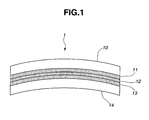
- FIG. 1 diagrammatically shows a structure of the laminated glass with the plastic film insert according to the present invention.
- a curved glass plate having a solar transmittance equal to or larger than 85% and which is under a bending process for a soda lime series glass plate manufactured by a float method is suitably used.
- the solar transmittance is a value calculated on a basis of JIS R3106: 1998.
- a colorless transparent Ethylene-Vinyl-Acetate (EVA) or PolyVinyl Butyral (PVB) is suitably used for the exterior side resin intermediate film.
- the solar transmittance of the exterior side resin intermediate film is desirable for the solar transmittance of the exterior side resin intermediate film to be equal to or larger than 85%.
- the plastic film on which the infrared ray reflective film is formed the plastic film made of the resin selected from polyethylene terephthalate, polyethylene naphthalate, polycarbonate, polymethylmethacrylate, polyether sulfone, nylon, polyarylate, cycloolefin polymer, or so forth is suitably used.
- a thickness of the plastic film is thinner than 30 ⁇ m, a handling of the film is difficult and it is easy to be curled due to a stress of the infrared ray reflective film or a hard coat film as will be described later.
- the thickness thereof is thicker than 200 ⁇ m, an outer appearance defect occurs due to a degassing failure at a time of a lamination process.
- the thickness desirably falls within a range of 30 ⁇ m through 200 ⁇ m.
- An electromagnetic wave used for broadcasting and communications is preferably transmitted if a multiple layer film of resins having different refractive indexes are used as the infrared ray reflective film laminated on the plastic film.
- the infrared ray reflective film is a multi-layer film having the number of layers of 50 through 200 by alternately laminating the resin films of different indexes of refractions. If the number of layers are less than 50 layers, the refraction index is small and, if the number of layers are in excess of 200 layers, the refraction index does not become large. Thus, it is preferable for this multi-layer film to be equal to or less than 200 layers.
- a resin film (1) having a thickness of t1 and a resin film (2) having the thickness of t2, both of resin films being mutually different indexes of refractions, are alternately laminated by 10 through 40 layers to form a unit lamination film. If the number of unit lamination films with thicknesses t1, t2 changed are 2 through 6, a range of a reflection wavelength can preferably be widened.
- the resin used for the infrared ray reflective film is selected from polymethylmethacrylate, polyethylene, polystyrene, polycarbonate, a blend of polyvinylidene fluoride and polymethylmethacrylate, a copolymer of ethylene and unsaturated monocarboxylic acid, a copolymer of styrene and methylmethacrylate, and so forth and can suitably be used.
- the glass plate In the laminated glass of the curved surface shape used for the window of an automotive vehicle and so forth, the glass plate is bent in the curved surface shape. Therefore, the plastic film on which the infrared ray reflective film is formed is inserted between two sheets of resin intermediate film. When the inserted plastic film is integrated at a lamination process, a wrinkle is easy to occur on the plastic film on which the infrared ray reflective film is formed. If circumstances require, a peel-off of the reflective film is developed.
- a thermal shrinkage of a plastic film on which the infrared ray reflective film is formed is in a range from 0.5 to 3% in a temperature range from 90°C through 150°C.
- B) A modulus of elasticity of the plastic film on which the infrared ray reflective film is formed in a temperature range from 90 through 150°C is in a range from 30MPa through 2000MPa.
- C) A rate of elongation of the plastic film on which the infrared ray reflective film is formed is equal to or less than 0.3% when a tensile force of 10N is applied to the plastic film per 1m width on which the infrared ray reflective film is formed in the temperature range of 90 through 150°C.
- the thermal shrinkage is larger than 3%, the infrared ray reflective film is not durable due to the shrinkage of the film and this brings out the outer appearance defect such that the film is cracked.
- the thermal shrinkage of the plastic film on which the infrared ray reflective film is formed in order to prevent the wrinkle of the plastic film on which the infrared ray reflective film is formed at the lamination process and the crack in the infrared ray reflective film, it is preferable for the thermal shrinkage of the plastic film on which the infrared ray reflective film is formed to fall in the range of 0.5 through 3% in the temperature range of 90 through 150°C. It is more preferable for the thermal shrinkage of the plastic film on which the infrared ray reflective film is formed in the temperature range of 90 through 150°C to be in the range from 0.5 through 2%.
- this transparent plastic film can suitably be used.
- a modulus of elasticity of the plastic film on which the infra-red reflective film is formed in a range from 30MPa to 2000MPa in a temperature range of 90 through 150°C and more preferably in a range from 30MPa to 500MPa.
- the modulus of elasticity of the plastic film on which the plastic film is formed can be determined from a stress-strain curved line in a temperature range of 90 through 150°C using a viscosity-elasticity measurement device. If the modulus of elasticity of the plastic film on which the infrared ray reflective film is formed is smaller than 30Mpa, the film is easy to be deformed according to a slight external force and the outer appearance defect in a wrinkle shape is easy to be developed on a whole surface of the laminated glass.
- the modulus of elasticity of the plastic film on which the infrared ray reflective film is formed is larger than 2000Mpa, a degassing failure is easy to occur in a case where the infrared ray reflective film is applied to a glass which is bent three-dimensionally since an air between the resin intermediate film and the plastic film on which the infrared ray reflective film is formed cannot completely be drained.
- the rate of elongation of the plastic film on which the infrared ray reflective film is formed is desirably 0.3% or smaller when the tensile force of 10N per 1m in width is applied to the plastic film on which the infrared ray reflective film is formed in the high temperature range of 90 through 150°C.
- the tensile force of 10N applied to the plastic film on which the infrared ray reflective film is formed per 1m in width corresponds to the tensile force which is to try to elongate the plastic film on which the infrared ray reflective film is formed and which is developed on the plastic film on which the infrared ray reflective film is formed, when the plastic film grasped by the resin intermediate films is at the high temperature and under the high pressure by means of the autoclave and, thereafter, the plastic film on which the infrared ray reflective film is formed is thermally molten by means of the resin intermediate films.
- the rate of elongation of the plastic film on which the infrared ray reflective film is formed is measured in the following sequence of procedures 1 through 5.
- Procedure 1 The plastic film on which the infrared ray reflective film is formed is cut out to provide a dimension of 15mm in length X 5mm in width which serves as a measurement specimen. Fixture jigs are attached on both ends of the measurement specimen and the length by which the measurement specimen is exposed between the fixture jigs at both ends is set to 10mm.
- Procedure 2 A load of tensile force of 10N per 1m width of the plastic film on which the infrared ray reflective film is formed is applied to the measurement specimen. In a case of the measurement specimen described in procedure 1, the load of 0.05N is applied to the measurement specimen.
- Procedure 3 A length of L 0 of the measurement specimen between the fixture jigs is measured.
- Procedure 4 After the measurement specimen is heated up to a predetermined measurement temperature which falls in a range between 90 and 150°C at 5°C/min and a length L of the measurement specimen between fixture jigs is measured at the predetermined measurement temperature.
- Procedure 5 The rate of elongation (%) is calculated according to (L 0 -L)/L x 100.
- a film of a silane coupling agent prefferably to be formed on a surface of the plastic film on which the infrared ray reflective film is not formed.
- the silane coupling agent serves to favor an adhesion of the plastic film on which the infrared ray reflective film is formed between the surface of the plastic film on which the infrared reflective film is formed and the resin intermediate film. Then, the silane coupling agent having an amino group, an isocyanate group, an epoxy group, and so forth can be used.
- a hard coat film to be formed between the plastic film of the plastic film on which the infrared ray reflective film is formed and the infrared ray reflective film.
- the interior side resin intermediate film is constituted by a film of Ethylene-Vinyl-Acetate (EVA) or PolyVinyl Butyral (PVB) in which various kinds of fine particles for absorbing the infrared ray are included in a range that does not impede a visible light transmissivity and a coloring matter is mixed to color the interior side intermediate film to provide the solar transmittance of 75% or less.
- EVA Ethylene-Vinyl-Acetate
- PVB PolyVinyl Butyral
- Metallic fine particles such as Ag, Al, Ti, and so forth, fine particles of a metallic nitride and a metallic oxide or electrically conductive transparent oxide particles such as ITO, ATO, AZO, GZO, IZO, and so forth are provided as fine particles for absorbing the infrared ray described above. From among these elements described above, one kind or more are selected to be included in interior side resin intermediate film 13 so that the heat insulation performance can be improved.
- the electrically conductive transparent oxide such as ITO, ATO, AZO, GZO, IZO, and so forth to be included in the interior side resin intermediate film.
- EVA or PVB In a case where EVA or PVB is colored, one of well known generally available various kinds of pigments or various kinds of dyes can be used as a coloring agent.
- an anthraquinone dye, an azo dye, an acridine dye, an indigoid dye, and, as various kinds of pigments, carbon black, red iron oxide, phthalocyanine blue, Prussian blue, Zinc ointment, an azo pigment, a styrenic pigment, and so forth can be used.
- a colored polyvinyl acetal film in which a polyvinyl acetal film is colored with the above-described dye or pigment and which is laminated with EVA or PVB may be used for the interior side resin intermediate film.
- a heat-ray absorbing glass having the solar transmittance less than 75% and having a transmission color of green, blue, bronze, gray, or so forth can suitably be used.
- the above-described heat-ray absorbing glass is prepared by including a metal such as Ce, Co, Ti, Fe, Se, Cr, and so forth in a clear glass.
- the heat-ray absorbing glasses From among the heat-ray absorbing glasses, it is preferable to use one or more of the heat-ray absorbing glasses in a green color and in a blue color since they have highly visible light transmittances so that a bright interior room can be achieved.
- a convex-and-recess shape embossing is carried out on a surface of each of resin intermediate films in order not to develop a devitrification or bubble fault due to a degassing failure at the time of the lamination process. It is difficult to make an optical measurement for each of resin intermediate films on the surface of which the embossing is carried out since the surface thereof is light scattered.
- the resin intermediate film on which the embossing is carried out is sandwiched by Polyethylene terephtalate (hereinafter, referred to as PET) films, and both sides of each of the films are grasped by the plane glass plates and bagged. Then, the air in the bag is absorbed.
- PET Polyethylene terephtalate
- the autoclave is used to perform the pressure application and the hear processing in the same way as the preparation of the laminated glass.
- the PET films are peeled off from the respective resin intermediate films and a specimen of the resin intermediate film whose surface is plane is prepared.
- the visible light transmittance and the solar transmittance are calculated in the same way as the glass plate in the method which conforms to JISR3106:1998.
- the laminated glass with the plastic film insert according to the present invention can be used for the window which is needed for the driving of the automotive vehicle by making the visible light transmittance prescribed in JISR3212:1998 equal to or larger than 70%.
- embodiments 1 through 4 illustrate the condition of (A) according to the present invention
- embodiments 5 and 6 illustrate the condition of (B) according to the present invention
- embodiments 7 and 8 illustrate the condition of (C) according to the present invention.
- the preparation of the plastic film on which the infrared ray reflective film is formed was carried out in the following way.
- unit lamination films L1 through L5 were laminated on PET film 16 to prepare plastic film 12 on which infrared ray reflective film 17 is formed.
- Unit lamination films L1 through L5 were formed using Polymethylmethacrylate (hereinafter, referred to as PMMA) for the resin film (1) having a low index of refraction and using Polyethylene terephthalate for the resin film (2) having a high index of refraction.
- PMMA Polymethylmethacrylate
- the layer having the low index of refraction formed by using PMMA is called a PMMA layer and the layer having the high index of refraction formed using the Polyethylene terephthalate is called a PET layer).
- the layers laminated by alternately repeating the PMMA layer (thickness of t1) having the same thicknesses (thickness of t2) were called unit lamination films L1 through L5.
- the PMMA layer was coated and formed in a roll coat method using a liquid solved by PMMA in 2-methoxyethyl acetate.
- the index of refraction was 1.49.
- the PET layer was coated while a pellet of PET was molten with an extruder.
- the index of refraction of the PET layer was 1.65.
- Fig. 4 shows a structure of the unit lamination film in a case where the number of times of repetitions were five times.
- Fig. 3 shows its film structure.
- Infrared ray reflective film B is a sequential lamination of L1 of the 15 times of the number of repetitions, L2 of the 5 times of the number of repetitions, and L3, L4, and L5 of respective 10 times of the number of repetitions on the plastic film.
- Infrared ray reflective film C is a sequential lamination of L1 of the 20 times opf the number of repetitions, L2 of the 10 times of the number of repetitions, L3, L4, and L5 of the respective 10 times of the number of repetitions.
- Table 1 represents the thickness of the PMMA layer and the PET layer in each of unit lamination films of L1 through L5 and number of layers.
- Table 2 represents the thickness of the unit lamination film and the thickness of the infrared ray reflective film.
- infrared ray reflective film A infrared ray reflective film B infrared ray reflective film C infrared ray reflective film D unit lamination film ( ⁇ m) L5 1.815 3.630 5.445 7.260 L4 1.665 3.330 4.995 6.660 L3 1.970 3.940 5.910 7.880 L2 1.740 1.740 3.480 6.960 L1 1.515 4.545 6.060 6.060 infrared ray reflective film( ⁇ m) 8.705 17.185 25.890 34.820
- Figs. 5 through 8 represent graphs, each representing the index of reflection in infrared ray reflective film A, B, C, and D film formed as infrared reflective film 17.
- the number of layers are 50 ( Fig. 5 )
- an effective reflective film is obtained as the infrared ray reflective film.
- the number of layers is in excess of 200 layers, the increase in the index of reflection cannot be expected. Therefore, it is preferable for the number of layers to be equal to 50 or larger but to be equal to or smaller than 200.
- a plastic film 12 on which the infrared ray reflective film shown in Fig. 3 was formed using the PET film having a thickness of 60 ⁇ m for plastic film 16 was prepared.
- Infrared ray reflective film D of Table 2 (having the thickness of about 34.8 ⁇ m) was used for infrared reflective film 17.
- the thermal shrinkage of plastic film 13 on which the infrared ray reflective film was formed was 1.5% in the MD direction and was 1% in the TD direction.
- the thermal shrinkage was measured as follows in conformity to JIS C 2318.
- a rectangular film 30 having a length of 150mm x width of 40mm was cut down and a diamond pen was used to indicate a marked line at a proximity to a center in the elongated direction thereof at a distance of about 100mm. After the marked line was indicated, rectangular film 30 was bisected into two equal parts of 150mm x 20mm.
- test pieces bisected was suspended vertically within a hot wind circulation type thermostatic oven and the temperature of the test piece was raised to a measurement temperature of 130°C at a rise temperature speed of about 5°C/minute and held for about 30 minutes at the measured temperature.
- the hot wind circulation type thermostatic oven was opened to the air so that a natural cooling for about 20°C/minutes and, furthermore, the test piece was held at room temperature for 30 minutes.
- thermocouple temperature meter was used for the temperature measurement and a temperature distribution within the hot wind circulation type temperature oven was within ⁇ 1°C.
- rectangular film 30 was cut down for each of three sheets of film for respective rectangular films 30 in the MD direction of PET film and in the TD direction thereof.
- Thermal shrinkage was derived from an average value of thermal shrinkages measured for three sheets of rectangular PET film.
- Plastic film 12 on which infrared ray reflective film 17 was formed was grasped by two sheets of PVB film, each having the thickness of 0.38mm.
- the laminated glass was prepared in the following way using the same shape two sheets of bent glass plate 10, 14, each sheet of glass plate having the dimension of 250mm x 350mm and the thickness of 2mm (a minimum value of the radius of curvature was 0.9m and a maximum value thereof was 1m).
- curved exterior side glass plate 10 and curved interior side glass plate 14 were prepared by bending a float glass. Minimum value of 0.9m of the radius of curvature was the value placed in the proximity of the surrounding section of glass plates 10, 14 and maximum value of 1m of the radius of curvature was the value at a center portion of glass plates 10, 14.
- interior side glass plate 14, interior side intermediate film 13, plastic film 12 on which infrared ray reflective film was formed, exterior side intermediate film 11, exterior side glass plate 10 were sequentially laminated, extra parts of exterior side intermediate film 11 extruded from the edge portion of the glass plate were cut and eliminated, and, thereafter, were pressure applied and degassing was carried out for 30 minutes in the autoclave heated to 130°C to perform the lamination process.
- the laminated glass from which the infrared ray of wavelength of 900nm through 1500nm was preferably reflected could be obtained.
- Plastic film 12 on which infrared ray reflective film shown in Fig. 3 was formed by laminating an acrylic hard coat film (not shown) on both surfaces of plastic film 16, using the PET film having the thickness of 100 ⁇ m for plastic film 16, and forming infrared ray reflective film A on one surface of plastic film 16 on which the hard coat film was formed.
- the thermal shrinkage of plastic film 12 on which the infrared ray reflective film was formed was 1.5% in the MD direction and was 1% in the TD direction when measured in the same way as in the first embodiment.
- Laminated film 1 on which this infrared ray reflective film was formed was prepared as shown in Fig. 1 using plastic film 12 on which this infrared ray reflective film was formed.
- the bent float glass was used for each of glass plates 10, 14 having the same magnitude and thickness as in the same way as embodiment 1 and having the radius of curvature in a range from 2.8m to 3m.
- Laminated glass 1 with plastic film insert in this embodiment having no wrinkle of plastic film 12 on which the infrared reflective film was formed and no crack in the infrared ray reflective film and having the favorable outer appearance was obtained.
- the PET film used in embodiment 1 was used for plastic film 16.
- the acrylic hard coat film (not shown) having the thickness of 2 ⁇ m was laminated on both surfaces of this plastic film 16 and infrared ray reflective film A was formed on the one side surface of plastic film 16.
- Plastic film 12 was prepared on which the infrared ray reflective film shown in Fig. 3 was formed.
- thermo shrinkage of plastic film 12 on which this infrared ray reflective film was formed was 1% in the MD direction and was 0.6% in the TD direction when measured in the same way as embodiment 1.
- laminated glass 1 with the plastic film insert in Fig. 1 was prepared in the same way as embodiment 1 using plastic film 12 on which this infrared ray reflective film was formed.
- Laminated glass 1 with the plastic film insert in this embodiment having a favorable outer appearance was obtained with the laminated glass having no wrinkle in the plastic film on which the infrared ray reflective film was formed and no crack in the infrared ray reflective film.
- the PET film having the thickness of 100 ⁇ m and having the thermal shrinkage of 4% in the MD direction and 3.5% in the TD direction at 130°C was used for plastic film 16.
- a heat treatment at 50°C was made, and, furthermore, infrared ray reflective film D in the same way as embodiment 1 was formed.
- plastic film 12 was prepared on which the infrared ray reflective film was formed.
- thermo shrinkage of plastic film 12 on which the infrared ray reflective film was formed was 2.0% in MD direction and 1.6% in TD direction when measured in the same way as embodiment 1.
- plastic glass 1 with plastic film insert shown in Fig. 1 was prepared in the same way as embodiment 1 using plastic film 12 on which this infrared ray reflective film was formed.
- the laminated film with the plastic film insert prepared in this embodiment obtained the laminated film with the plastic film insert having the favorable outer appearance with no wrinkle in the plastic film on which the infrared ray reflective film was formed and with no crack of the infrared ray reflective film.
- Laminated glass 1 with the plastic film insert using the bent glass plate as shown in Fig. 1 was prepared. Twos of curved glass plates, each having the radius of curvature of 1200mm, the magnitude of 250mm x 350mm, and the thickness of 2mm, were used for curved glass plates 10, 14.
- Infrared ray reflective film D was formed on plastic film (PET film) 16 having the thickness of 50 ⁇ m and plastic film 12 having a modulus of elasticity of 40MPa at 130°C was used.
- Laminated glass 1 with the plastic film insert prepared in this embodiment was the laminated glass with the plastic film insert having the favorable outer appearance with no wrinkle observation.
- the hard coat film (not shown) and infrared ray reflective film A were formed on one side surface of the PET film having the thickness of 100 ⁇ m and plastic film 12 on which the infrared ray reflective film shown in Fig. 3 was formed.
- the acrylic hard coat film was used and coated to have the thickness of 5 ⁇ m.
- the modulus of elasticity of plastic film 12 on which the infrared reflective film in the preferred embodiment was formed at 130°C was 1000MPa.
- Laminated glass 1 with plastic film insert shown in Fig. 1 was prepared in the same way as embodiment 5 other than the use of plastic film 12 on which the infrared ray reflective film described above was formed.
- Laminated glass 1 with plastic film insert in this embodiment observed no wrinkle and had the favorable outer appearance.
- Laminated glass 1 with the plastic film insert shown in Fig. 1 was prepared using the bent glass plates of soda lime glasses through the float method, each having the radius of curvature of 1200mm, the thickness of 2mm, and the magnitude of 250mm x 300mm, for glass plates 10, 14.
- the PET film (thickness of 100 ⁇ m) was used for plastic film 16.
- Infrared ray reflective film A was formed on this PET film and the rate of elongation measured at measurement temperature of 150°C under the load of tensile force of 10N per 1m of the film width was 0.02% in the MD direction and was 0.13% in the TD direction.
- Interior side glass plate 14, interior side intermediate film 13, plastic film 12 on which infrared reflective film was formed, exterior side intermediate film 11, and exterior side intermediate film 11, and exterior side glass plate were sequentially overlapped, and extra parts of interior side intermediate film 13 protruded from the edge of the glass plate, plastic film 12 on which the infrared ray reflective film was formed, and exterior side intermediate film 11 were cut and eliminated, and, thereafter, the remaining part thereof was heated for 30 minutes and at 130°C within the autoclave and the lamination process was carried out with the pressure application and degassing. Then, laminated glass 1 with the plastic film insert having the favorable outer appearance was prepared.
- the acrylic hard coat film (not shown) was laminated to have the thickness of 5 ⁇ m was laminated on both surfaces of PET film 16 having the thickness of 100 ⁇ m and infrared ray reflective film D was formed on one side of PET film 16 on which the hard coat film was formed.
- the rate of elongation (a state in which the tensile force of 10N per width of 1m of the film is loaded) of plastic film 12 on which infrared ray reflective film D was formed and the hard coat film (not shown) was formed was 0.01% or smaller in the MD direction and was 0.19% in the TD direction.
- Interior side glass plate 14 interior side intermediate film 13, plastic film 12 on which the infrared ray reflective film was formed, exterior side intermediate film 11, and exterior side glass plate 10 were sequentially overlapped, were heated for 30 minutes at 130°C, and the lamination process under the pressure application and degassing was performed to prepare the laminated glass with plastic film insert 1 shown in Fig. 1 .
- the PET film used in embodiment 1 was used for plastic film 16, infrared ray reflective film A was formed in the same way as embodiment 1, and plastic film 12 on which infrared ray reflective film in Fig. 3 was formed was prepared.
- the thermal shrinkage of plastic film 12 on which the infrared ray reflective film was formed was 0.4% in the MD direction and was 0.2% in the TD direction.
- laminated glass 1 with plastic film 12 on which this infrared ray reflective film was formed was prepared in the same way as embodiment 1.
- the PET film having the thermal shrinkage at 130°C in the MD direction of 1.0% and in the TD direction of 0.5% and having the thickness of 100 ⁇ m was used for plastic film 16.
- acrylic hard coat film (not shown) with the thickness of 2 ⁇ m was formed for this PET film. Furthermore, infrared ray reflective film D which was the same as embodiment 1 was formed. Thus, plastic film 12 on which the infrared ray reflective film was formed was prepared.
- thermo shrinkage of plastic film 12 on which this infrared ray reflective film was formed was measured in the same way as embodiment 1. Then, the measured thermal shrinkage was 0.3% in the MD direction and was 0.2% in the TD direction.
- plastic film 12 on which this infrared ray reflective film was formed laminated glass with the plastic film insert 1 having the structure shown in Fig. 1 was prepared.
- plastic film 16 having the thermal shrinkage of 8% in the MD direction and 7% in the TD direction at the temperature of 130°C was used for plastic film 16.
- the acrylic hard coat film (not shown) was formed to have the thickness of 2 ⁇ m for this PET film.
- plastic film 12 on which the infrared ray reflective film D, in the same way as embodiment 1, was formed was prepared.
- the thermal shrinkage of plastic film 12 on which the infrared ray reflective film was formed was measured in the same way as embodiment 1 and was 7% in the MD direction and 6% in the TD direction.
- laminated film with the plastic film insert 1 shown in Fig. 1 was prepared in the same way as embodiment 1 using plastic film 12 on which the infrared ray reflective film was formed.
- a wrinkle defect was not found on plastic film 12 on which the infrared ray reflective film was formed, in the prepared laminated glass with the plastic film insert 1, but cracks were generated on the whole surface of infrared ray reflective film 17 and it was difficult to be suited for practical use.
- Laminated glass with the plastic film insert 1 was prepared in the same way as embodiment 1 except that the curved same shape two sheets of glass plate, each having the magnitude of 250mm x 350mm, having the thickness of 2mm, and having the radius of curvature of the minimum value of 0.7m at the proximity of the surrounding section and the radius of curvature of 0.8m at the center thereof, were used for glass plates 10, 14.
- the wrinkle of the plastic film on which the infrared ray reflective film was formed was observed at the surrounding section of the prepared laminated glass with the plastic film insert 1 and, since the outer appearance defect occurred, it was not suitable for the practical use.
- Laminated glass with plastic film insert 1 was prepared in the same way as embodiment 5 except that infrared ray reflective film A was formed on the PET film having the thickness of 50 ⁇ m and the plastic film on which the infrared ray reflective film having the modulus of elasticity at 130°C of 20MPa was formed was used.
- the wrinkle outer appearance defect was developed on the whole surface of laminated glass with the plastic film insert prepared in this comparative example.
- Laminated glass with the plastic film insert 5 was prepared in the same way as embodiment 5 except that infrared ray reflective film D was formed on PET film 16 having the thickness of 100 ⁇ m and the plastic film on which the infrared ray reflective film was formed having the elasticity at 130°C of 3000MPa was used.
- Laminated glass with plastic film insert 1 prepared in this comparative example indicated a degassing failure state in which air between the PVB at the center portion of glass and the plastic film was left and could not be put into practice.
- Laminated glass with plastic film insert 1 shown in Fig. 1 was prepared in the same way as embodiment 7 except that PET film (having the thickness of 100 ⁇ m) having the rate of elongation of 0.3% at 130°C was used for plastic film 12 on which the infrared ray reflective film was formed.
- the wrinkle outer appearance defect was developed on the whole surface of prepared laminated glass with the plastic film insert 1.
Landscapes
- Joining Of Glass To Other Materials (AREA)
- Special Wing (AREA)
- Laminated Bodies (AREA)
Abstract
Description
- The present invention relates to a laminated glass prepared by laminating a glass plate, a resin intermediate film, a transparent plastic film, another resin intermediate film, and another glass plate in this sequence and, more particularly, relates to the laminated glass having an infrared ray reflective film formed on the transparent plastic film and having a heat insulation function.
- Many trials to produce a pleasant interior space have been made by suppressing a temperature rise in the interior space, with a heat radiation energy of sun light flowing into the interior space via a window glass reduced, by suppressing a consumption of an electrical energy consumed through a drive of a cooling device, and by maintaining a high visible light transmittance of the window glass.
- A
patent document 1 describes that it has been proposed that the laminated glass having a resin interlayer film interposed between at least two sheets of transparent glass plate-like body, electrically conductive ultra-fine particles, each of the ultra-fine particles having a particle diameter up to 0.2µm, are dispersed in the interlayer film so that the laminated glass having a solar transmittance which can be reduced to about 50% while the transmittance in a visible light area is highly maintained can be achieved. - It should, however, be noted that, since the laminated glass disclosed in
patent document 1 serves to absorb light in the infrared area, the laminated glass itself becomes warm to increase the temperature, and radiant rays directed from the laminated glass to the interior space called a re-radiation for the radiation against sun light rays are radiated, the temperature in the interior space is raised after a lapse of a long time. - A patent document 2 discloses an infrared ray reflective film which is a lamination of dielectrics having different indexes of refractions, as the infrared ray reflective film which reflects the infrared ray without use of the electrically conductive film. In addition, each of patent documents 3 and 4 discloses the infrared ray reflective film which is a lamination of resin films having different indexes of refractions.
- It is known as the laminated glass having a heat ray reflection function that the laminated glass is prepared using a three-layer structure intermediate film in which the transparent plastic film on which the infrared reflective film is formed is inserted between the two sheets of resin intermediate film.
- Ordinarily, the laminated glass is processed at a high temperature and under a high pressure using an autoclave. Thus, the glass plate and three-layer structure intermediate film are heat molten to each other by means of the resin intermediate film.
- For example, a patent document 5 discloses the laminated glass in which a flexible lamination body in which a heat-ray reflective plastic film formed by a thin film on a polyester film is sandwiched between two sheets of resin intermediate film is inserted between two sheets of glass plate to be laminated.
- In addition, patent document 4 discloses an infrared ray shielding film constituted by a multiple number of plastic layers and sandwiched between two sheets of polyvinyl butyral sheet, this infrared ray shielding film being sandwiched between two sheets of glass plate. Patent document 4 also describes that this infrared ray shielding film has the shrinkage of 2% or smaller under a process of 150°C and for 30 minutes in both of a film formation direction thereof and in a width direction thereof, from a viewpoint of preventing an occurrence of cracks and a peeling off between the glass and the film after an adherence of the glass plates on the infra-red ray shielding film, and has a shrinkage difference of 0.5% or smaller under the process of 150 °C and for 30 minutes, from the viewpoint of preventing a wrinkle generation.
- Furthermore, a patent document 6 describes that a functional film having a selective light transmittance and an electrical conductivity is sandwiched between polyvinyl butyral (PVB) films to form the laminated glass, in order to prevent a defect such as a wrinkle when a polyethylene terephthalate film is sandwiched between two sheets of PVB film and is laminated to form the laminated glass and, in order to prevent an outer appearance default such as a wrinkle, a thermal expansion rate of a polyester terephthalate used for the functional film is 0.1 through 1.0% in one direction, and the thermal shrinkage of the polyester terephthalate in an orthogonal direction to the one direction is 0.1 through 1.0%. A patent document 7 describes that an infrared ray reflective film in which a film of oxide indium or silver is formed on a plastic film is used and the infrared ray reflective film having the thermal shrinkage of the plastic film during a thermal process of the plastic film of 1 through 20% when preparing the laminated glass.
- As a film to reflect the infrared ray, patent documents 8 and 9 describe the infrared ray reflective films including resin multi-layer films.
-
- Patent document 1: a Japanese Patent Application first Publication (tokkai) No.
Heisei 8-259279 - Patent document 2: a Japanese Patent Application first Publication (tokkai) No.
Heisei 2-160641 - Patent document 3: a Japanese Patent Application first Publication (tokuhyo) No.
2003-515754 - Patent document 4: a Japanese Patent Application first Publication (saikohyo) No.
2005-040868 - Patent document 5: a Japanese Patent Application first Publication (tokkai) No.
Showa 56-032352 - Patent document 6: a Japanese Patent Application first Publication (tokkai) No.
Showa 60-225747 - Patent document 7: a Japanese Patent Application first Publication (tokkai) No.
Heisei 6-270318 - Patent document 8: a Japanese Patent Application first Publication (tokkai) No.
Heisei 4-295804 - Patent document 9: a Japanese Patent Application first Publication (tokkai) No.
Heisei 4-313704 - It is an object of the present invention to provide a laminated glass having a high visible light transmittance, having a high index of reflection in an infrared ray region and a favorable heat insulation effect in the infrared ray region, and of an infrared reflection of a curved surface form.
- According to one aspect of the present invention, there is provided a laminated glass with a plastic film insert (a fist glass), prepared using a film constituted by grasping the plastic film between two sheets of resin intermediate film, comprising: a glass plate bent through a bending process thereof; and the film, wherein the plastic film is one plastic film selected from polyethylene terephthalate, polyethylene naphthalate, polycarbonate, polymethylmethacrylate, polyether sulfone, nylon, polyarylate, and cycloolefin polymer, a thickness of the plastic film ranges from 30 to 200µm, an infrared ray reflective film in which resin films having different indexes of refractions are alternately laminated is formed on the plastic film, and the plastic film on which the infrared ray reflective films is formed satisfies any of the following conditions of (A): a thermal shrinkage of the plastic film falls in a range from 0.5% to 3% in a temperature range of 90 through 150°C, (B): a modulus of elasticity falls in a range from 30MPa to 2000MPa, and (C): a rate of elongation of the plastic film is 0.3% or less when a tensile force of 10N is applied to the plastic film per one-meter width.
- The first glass may be the laminated glass with the plastic film insert (a second glass), wherein a radius of curvature of the bent glass plate is in a range from 0.9m to 3m.
- The first or second glass may be the laminated glass with the plastic film insert (a third glass), wherein the infrared ray reflective film comprises a multi-layer film having a number of layers of 50 through 200 and having an alternate lamination of a resin film (1) and a resin film (2), both of the resin films having different indexes of refraction.
- Any one of the first through third glasses may be the laminated glass with the plastic film insert (a fourth glass), wherein the infrared ray reflective film is formed with unit lamination films laminated by 2 through 6 with thicknesses of t1 and t2 varied, each of the unit lamination films being an alternate lamination of totally 10 through 40 layers of a resin film (1) having the thickness of t1 and another resin film (2) having the thickness of t2.
- Any one of the first through fourth glasses may be the laminated glass with the plastic film insert (a fifth glass), wherein one sheet of resin intermediate film is an infrared ray absorption film containing particles of an electrically conductive oxide for an infrared ray absorbing material and a thickness of the resin intermediate film is in a range from 0.3 through 1.2mm.
- Any one of the first through fifth glasses may be the laminated glass with the plastic film insert (a sixth glass), wherein a hard coat film is formed on an interface between the plastic film and the resin intermediate film.
- Any one of the first through sixth glasses may be the laminated glass with the plastic film insert (a seventh glass), wherein a film of a silane coupling agent is formed on an interface between the plastic film and the resin intermediate films.
- Any one of the first through seventh glasses may be the laminated glass with the plastic film insert (an eighth glass), wherein a film of a silane coupling agent is formed on an interface between the hard coat film and the resin intermediate film.
-
-
Fig. 1 is a rough cross sectional view representing a structure of a laminated glass with a plastic film insert according to the present invention using a curved glass plate. -
Fig. 2 is a plan view representing a plastic film on which an infrared ray reflective film is formed before and after measurement of a thermal shrinkage. -
Fig. 3 is a rough cross sectional view representing a structure of the plastic film on which the infrared ray reflective film is formed. -
Fig. 4 is a rough cross sectional view representing a unit lamination film in a case where the number of repetitions is five times. -
Fig. 5 is a graph representing a reflection of 50-layer infrared ray reflective film. -
Fig. 6 is a graph representing a reflection of 100-layer infrared ray reflective film. -
Fig. 7 is a graph representing a reflection of 150-layer infrared ray reflective film. -
Fig. 8 is a graph representing a reflection of 200-layer infrared ray reflective film. - A laminated glass with a plastic film insert according to the present invention enables a provision of the laminated glass with the plastic film insert having a high index of reflection in a visible light region, having a favorable heat insulation effect, and having no wrinkle of the inserted plastic film and no peeling off of an infrared ray reflective film.
- The laminated glass with the plastic film insert according to the present invention is the laminated glass of the curved surface shape laminated in a sequence of an exterior side glass plate, an exterior side resin intermediate film, a plastic film on which an infrared ray reflective film is formed, an interior side resin intermediate film, and an interior side glass plate.
- A cross sectional view shown in
Fig. 1 diagrammatically shows a structure of the laminated glass with the plastic film insert according to the present invention. For the exterior side glass plate, a curved glass plate having a solar transmittance equal to or larger than 85% and which is under a bending process for a soda lime series glass plate manufactured by a float method is suitably used. - The solar transmittance is a value calculated on a basis of JIS R3106: 1998. A colorless transparent Ethylene-Vinyl-Acetate (EVA) or PolyVinyl Butyral (PVB) is suitably used for the exterior side resin intermediate film.
- In order to effectuate an effect of the infrared ray reflective film and to effectuate a heat insulation performance of the laminated glass, it is desirable for the solar transmittance of the exterior side resin intermediate film to be equal to or larger than 85%.
- The plastic film on which the infrared ray reflective film is a formation of the infrared ray reflective film on a transparent plastic film. It is preferable for the solar transmittance of the plastic film on which the infrared ray reflective film is formed to be equal to or larger than 20%.
- For the plastic film on which the infrared ray reflective film is formed, the plastic film made of the resin selected from polyethylene terephthalate, polyethylene naphthalate, polycarbonate, polymethylmethacrylate, polyether sulfone, nylon, polyarylate, cycloolefin polymer, or so forth is suitably used.
- If a thickness of the plastic film is thinner than 30µm, a handling of the film is difficult and it is easy to be curled due to a stress of the infrared ray reflective film or a hard coat film as will be described later. On the other hand, if the thickness thereof is thicker than 200µm, an outer appearance defect occurs due to a degassing failure at a time of a lamination process. Hence, the thickness desirably falls within a range of 30 µm through 200µm.
- An electromagnetic wave used for broadcasting and communications is preferably transmitted if a multiple layer film of resins having different refractive indexes are used as the infrared ray reflective film laminated on the plastic film.
- It is preferable that the infrared ray reflective film is a multi-layer film having the number of layers of 50 through 200 by alternately laminating the resin films of different indexes of refractions. If the number of layers are less than 50 layers, the refraction index is small and, if the number of layers are in excess of 200 layers, the refraction index does not become large. Thus, it is preferable for this multi-layer film to be equal to or less than 200 layers.
- Furthermore, a resin film (1) having a thickness of t1 and a resin film (2) having the thickness of t2, both of resin films being mutually different indexes of refractions, are alternately laminated by 10 through 40 layers to form a unit lamination film. If the number of unit lamination films with thicknesses t1, t2 changed are 2 through 6, a range of a reflection wavelength can preferably be widened.
- The resin used for the infrared ray reflective film is selected from polymethylmethacrylate, polyethylene, polystyrene, polycarbonate, a blend of polyvinylidene fluoride and polymethylmethacrylate, a copolymer of ethylene and unsaturated monocarboxylic acid, a copolymer of styrene and methylmethacrylate, and so forth and can suitably be used.
- In the laminated glass of the curved surface shape used for the window of an automotive vehicle and so forth, the glass plate is bent in the curved surface shape. Therefore, the plastic film on which the infrared ray reflective film is formed is inserted between two sheets of resin intermediate film. When the inserted plastic film is integrated at a lamination process, a wrinkle is easy to occur on the plastic film on which the infrared ray reflective film is formed. If circumstances require, a peel-off of the reflective film is developed.
- In order to prevent this phenomenon, it is preferable to satisfy either one or more of the following conditions of (A), (B), and (C) in a case of the curved glass plate having a radius of curvature in which the curvature ranges from 0.9m to 3m.
- It should be noted that the reason of the selected range of curvature which is from 0.9m to 3m is that it is difficult to eliminate the occurrence of the wrinkle. If the curvature is in excess of 3m, a difference thereof from a plane glass plate is not present and it becomes unnecessary to satisfy the following conditions of (A), (B), and (C).
- (A) A thermal shrinkage of a plastic film on which the infrared ray reflective film is formed is in a range from 0.5 to 3% in a temperature range from 90°C through 150°C. (B) A modulus of elasticity of the plastic film on which the infrared ray reflective film is formed in a temperature range from 90 through 150°C is in a range from 30MPa through 2000MPa.
(C) A rate of elongation of the plastic film on which the infrared ray reflective film is formed is equal to or less than 0.3% when a tensile force of 10N is applied to the plastic film per 1m width on which the infrared ray reflective film is formed in the temperature range of 90 through 150°C. - It should be noted that, if the thermal shrinkage of the plastic film on which the infrared ray reflective film is formed in the temperature range of 90 through 150°C is smaller than 0.5%, an outer appearance defect such that the infrared ray reflective film at a surrounding section of a curved glass becomes loose and provides a wrinkle is developed.
- In addition, if the thermal shrinkage is larger than 3%, the infrared ray reflective film is not durable due to the shrinkage of the film and this brings out the outer appearance defect such that the film is cracked.
- Hence, in order to prevent the wrinkle of the plastic film on which the infrared ray reflective film is formed at the lamination process and the crack in the infrared ray reflective film, it is preferable for the thermal shrinkage of the plastic film on which the infrared ray reflective film is formed to fall in the range of 0.5 through 3% in the temperature range of 90 through 150°C. It is more preferable for the thermal shrinkage of the plastic film on which the infrared ray reflective film is formed in the temperature range of 90 through 150°C to be in the range from 0.5 through 2%.
- Since, in a transparent plastic film, the plastic film prepared through a stretching method such as a successively biaxial stretching method leaves a stress developed at the time of a plastic film preparation process in an inside of the plastic film and the stress is easy to be relieved at the time of a thermal processing and the plastic film becomes easy to be relieved, this transparent plastic film can suitably be used.
- In addition, in a high-temperature-and-highpressure process using an autoclave, in order to prevent a winkle from being developed on the plastic film on which the infrared ray reflective film is formed, it is desirable for a modulus of elasticity of the plastic film on which the infra-red reflective film is formed to be in a range from 30MPa to 2000MPa in a temperature range of 90 through 150°C and more preferably in a range from 30MPa to 500MPa.
- If the modulus of elasticity of the plastic film on which the plastic film is formed can be determined from a stress-strain curved line in a temperature range of 90 through 150°C using a viscosity-elasticity measurement device. If the modulus of elasticity of the plastic film on which the infrared ray reflective film is formed is smaller than 30Mpa, the film is easy to be deformed according to a slight external force and the outer appearance defect in a wrinkle shape is easy to be developed on a whole surface of the laminated glass.
- If the modulus of elasticity of the plastic film on which the infrared ray reflective film is formed is larger than 2000Mpa, a degassing failure is easy to occur in a case where the infrared ray reflective film is applied to a glass which is bent three-dimensionally since an air between the resin intermediate film and the plastic film on which the infrared ray reflective film is formed cannot completely be drained.
- Or alternatively, under a high-temperature-and-high-pressure process by means of the autoclave, in order to prevent the wrinkle from being developed on the plastic film, the rate of elongation of the plastic film on which the infrared ray reflective film is formed is desirably 0.3% or smaller when the tensile force of 10N per 1m in width is applied to the plastic film on which the infrared ray reflective film is formed in the high temperature range of 90 through 150°C.
- The tensile force of 10N applied to the plastic film on which the infrared ray reflective film is formed per 1m in width corresponds to the tensile force which is to try to elongate the plastic film on which the infrared ray reflective film is formed and which is developed on the plastic film on which the infrared ray reflective film is formed, when the plastic film grasped by the resin intermediate films is at the high temperature and under the high pressure by means of the autoclave and, thereafter, the plastic film on which the infrared ray reflective film is formed is thermally molten by means of the resin intermediate films.
- The rate of elongation of the plastic film on which the infrared ray reflective film is formed is measured in the following sequence of
procedures 1 through 5. Procedure 1: The plastic film on which the infrared ray reflective film is formed is cut out to provide a dimension of 15mm in length X 5mm in width which serves as a measurement specimen. Fixture jigs are attached on both ends of the measurement specimen and the length by which the measurement specimen is exposed between the fixture jigs at both ends is set to 10mm.
Procedure 2: A load of tensile force of 10N per 1m width of the plastic film on which the infrared ray reflective film is formed is applied to the measurement specimen. In a case of the measurement specimen described inprocedure 1, the load of 0.05N is applied to the measurement specimen. Procedure 3: A length of L0 of the measurement specimen between the fixture jigs is measured.
Procedure 4: After the measurement specimen is heated up to a predetermined measurement temperature which falls in a range between 90 and 150°C at 5°C/min and a length L of the measurement specimen between fixture jigs is measured at the predetermined measurement temperature. Procedure 5: The rate of elongation (%) is calculated according to (L0 -L)/L x 100. - It is, furthermore, preferable for a film of a silane coupling agent to be formed on a surface of the plastic film on which the infrared ray reflective film is not formed.
- The silane coupling agent serves to favor an adhesion of the plastic film on which the infrared ray reflective film is formed between the surface of the plastic film on which the infrared reflective film is formed and the resin intermediate film. Then, the silane coupling agent having an amino group, an isocyanate group, an epoxy group, and so forth can be used.
- In addition, it is preferable for a hard coat film to be formed between the plastic film of the plastic film on which the infrared ray reflective film is formed and the infrared ray reflective film.
- It is often a case where, depending upon the plastic film to be inserted between the resin intermediate films, the adhesion of the plastic film to the resin intermediate film is not favorable and a white cloud is developed when the infrared ray reflective film is formed. These inconveniences described above can be solved by forming the hard coat film on an interface. It is preferable that the interior side resin intermediate film is constituted by a film of Ethylene-Vinyl-Acetate (EVA) or PolyVinyl Butyral (PVB) in which various kinds of fine particles for absorbing the infrared ray are included in a range that does not impede a visible light transmissivity and a coloring matter is mixed to color the interior side intermediate film to provide the solar transmittance of 75% or less.
- Metallic fine particles such as Ag, Al, Ti, and so forth, fine particles of a metallic nitride and a metallic oxide or electrically conductive transparent oxide particles such as ITO, ATO, AZO, GZO, IZO, and so forth are provided as fine particles for absorbing the infrared ray described above. From among these elements described above, one kind or more are selected to be included in interior side resin
intermediate film 13 so that the heat insulation performance can be improved. - Especially, it is desirable for the electrically conductive transparent oxide such as ITO, ATO, AZO, GZO, IZO, and so forth to be included in the interior side resin intermediate film.
- In a case where EVA or PVB is colored, one of well known generally available various kinds of pigments or various kinds of dyes can be used as a coloring agent.
- As various kinds of dyes, an anthraquinone dye, an azo dye, an acridine dye, an indigoid dye, and, as various kinds of pigments, carbon black, red iron oxide, phthalocyanine blue, Prussian blue, Zinc ointment, an azo pigment, a styrenic pigment, and so forth can be used.
- Furthermore, a colored polyvinyl acetal film in which a polyvinyl acetal film is colored with the above-described dye or pigment and which is laminated with EVA or PVB may be used for the interior side resin intermediate film.
- As the interior side glass plate, a heat-ray absorbing glass having the solar transmittance less than 75% and having a transmission color of green, blue, bronze, gray, or so forth can suitably be used. The above-described heat-ray absorbing glass is prepared by including a metal such as Ce, Co, Ti, Fe, Se, Cr, and so forth in a clear glass.
- From among the heat-ray absorbing glasses, it is preferable to use one or more of the heat-ray absorbing glasses in a green color and in a blue color since they have highly visible light transmittances so that a bright interior room can be achieved.
- A convex-and-recess shape embossing is carried out on a surface of each of resin intermediate films in order not to develop a devitrification or bubble fault due to a degassing failure at the time of the lamination process. It is difficult to make an optical measurement for each of resin intermediate films on the surface of which the embossing is carried out since the surface thereof is light scattered. The resin intermediate film on which the embossing is carried out is sandwiched by Polyethylene terephtalate (hereinafter, referred to as PET) films, and both sides of each of the films are grasped by the plane glass plates and bagged. Then, the air in the bag is absorbed. At this time, the autoclave is used to perform the pressure application and the hear processing in the same way as the preparation of the laminated glass. Thereafter, the PET films are peeled off from the respective resin intermediate films and a specimen of the resin intermediate film whose surface is plane is prepared. Then, using the resin intermediate film whose surface is plane, the visible light transmittance and the solar transmittance are calculated in the same way as the glass plate in the method which conforms to JISR3106:1998.
- It should be noted that it is preferable that the laminated glass with the plastic film insert according to the present invention can be used for the window which is needed for the driving of the automotive vehicle by making the visible light transmittance prescribed in JISR3212:1998 equal to or larger than 70%.
- The following
embodiments 1 through 4 illustrate the condition of (A) according to the present invention, embodiments 5 and 6 illustrate the condition of (B) according to the present invention, and embodiments 7 and 8 illustrate the condition of (C) according to the present invention. - The preparation of the plastic film on which the infrared ray reflective film is formed was carried out in the following way.
- As illustrated in
Fig. 3 , unit lamination films L1 through L5 were laminated onPET film 16 to prepareplastic film 12 on which infrared rayreflective film 17 is formed. - Unit lamination films L1 through L5 were formed using Polymethylmethacrylate (hereinafter, referred to as PMMA) for the resin film (1) having a low index of refraction and using Polyethylene terephthalate for the resin film (2) having a high index of refraction. (The layer having the low index of refraction formed by using PMMA is called a PMMA layer and the layer having the high index of refraction formed using the Polyethylene terephthalate is called a PET layer). The layers laminated by alternately repeating the PMMA layer (thickness of t1) having the same thicknesses (thickness of t2) were called unit lamination films L1 through L5.
- The PMMA layer was coated and formed in a roll coat method using a liquid solved by PMMA in 2-methoxyethyl acetate. The index of refraction was 1.49.
- The PET layer was coated while a pellet of PET was molten with an extruder. The index of refraction of the PET layer was 1.65.
- The number of times of repetitions when the PMMA layer or the PET layer was one lamination unit were 5 times through 20 times (this is called a unit lamination layer film L).
Fig. 4 shows a structure of the unit lamination film in a case where the number of times of repetitions were five times. - If the film thicknesses of individual PMMA layers and PET layers were changed and the unit lamination films in which the number of lamination layers are five layers (L1 through L5) to provide infrared lay reflection film A.
Fig. 3 shows its film structure. - Infrared ray reflective film B is a sequential lamination of L1 of the 15 times of the number of repetitions, L2 of the 5 times of the number of repetitions, and L3, L4, and L5 of respective 10 times of the number of repetitions on the plastic film. Infrared ray reflective film C is a sequential lamination of L1 of the 20 times opf the number of repetitions, L2 of the 10 times of the number of repetitions, L3, L4, and L5 of the respective 10 times of the number of repetitions. Table 1 represents the thickness of the PMMA layer and the PET layer in each of unit lamination films of L1 through L5 and number of layers. Table 2 represents the thickness of the unit lamination film and the thickness of the infrared ray reflective film.
-
[Table 1] Thickness of one layer (µm) The number of layers of unit Lamination film unit lamination film PMMA layer t1 PET layer t2 infrared ray reflective film A infrared ray reflective film B infrared ray reflective film C infrared ray reflective film D L5 0.172 0.191 each 5 layer each 10 layer each 15 layer each 20 layer L4 0.158 0.175 each 5 layer each 10 layer each 15 layer each 20 layer L3 0.187 0.207 each 5 layer each 10 layer each 15 layer each 20 layer L2 0.165 0.183 each 5 layer each 5 layer each 10 layer each 20 layer L1 0.144 0.159 each 5 layer each 15 layer each 20 layer each 20 layer -
[Table 2] infrared ray reflective film A infrared ray reflective film B infrared ray reflective film C infrared ray reflective film D unit lamination film (µm) L5 1.815 3.630 5.445 7.260 L4 1.665 3.330 4.995 6.660 L3 1.970 3.940 5.910 7.880 L2 1.740 1.740 3.480 6.960 L1 1.515 4.545 6.060 6.060 infrared ray reflective film(µm) 8.705 17.185 25.890 34.820 -
Figs. 5 through 8 represent graphs, each representing the index of reflection in infrared ray reflective film A, B, C, and D film formed as infraredreflective film 17. In a case where the number of layers are 50 (Fig. 5 ), an effective reflective film is obtained as the infrared ray reflective film. If the number of layers is in excess of 200 layers, the increase in the index of reflection cannot be expected. Therefore, it is preferable for the number of layers to be equal to 50 or larger but to be equal to or smaller than 200. - A
plastic film 12 on which the infrared ray reflective film shown inFig. 3 was formed using the PET film having a thickness of 60 µm forplastic film 16 was prepared. Infrared ray reflective film D of Table 2 (having the thickness of about 34.8 µm) was used for infraredreflective film 17. The thermal shrinkage ofplastic film 13 on which the infrared ray reflective film was formed was 1.5% in the MD direction and was 1% in the TD direction. - The thermal shrinkage was measured as follows in conformity to JIS C 2318.
- As shown in
Fig. 2 , arectangular film 30 having a length of 150mm x width of 40mm was cut down and a diamond pen was used to indicate a marked line at a proximity to a center in the elongated direction thereof at a distance of about 100mm. After the marked line was indicated,rectangular film 30 was bisected into two equal parts of 150mm x 20mm. - One of test pieces bisected was suspended vertically within a hot wind circulation type thermostatic oven and the temperature of the test piece was raised to a measurement temperature of 130°C at a rise temperature speed of about 5°C/minute and held for about 30 minutes at the measured temperature.
- Thereafter, the hot wind circulation type thermostatic oven was opened to the air so that a natural cooling for about 20°C/minutes and, furthermore, the test piece was held at room temperature for 30 minutes.
- A thermocouple temperature meter was used for the temperature measurement and a temperature distribution within the hot wind circulation type temperature oven was within ±1°C.
- Distances of L1, L2 between the marked lines were measured for
test piece 31 of the bisected test pieces held at room temperature and fortest piece 32 thereof heated at the measurement temperature using a scan type laser microscope 1LM21D made by Lasertech Corporation. - Thermal shrinkage (%) was determined by calculating a formula of (L1 - L2)/
L1 x 100. - In addition,
rectangular film 30 was cut down for each of three sheets of film for respectiverectangular films 30 in the MD direction of PET film and in the TD direction thereof. Thermal shrinkage was derived from an average value of thermal shrinkages measured for three sheets of rectangular PET film.Plastic film 12 on which infrared rayreflective film 17 was formed was grasped by two sheets of PVB film, each having the thickness of 0.38mm. Furthermore, the laminated glass was prepared in the following way using the same shape two sheets ofbent glass plate - It should be noted that curved exterior
side glass plate 10 and curved interiorside glass plate 14 were prepared by bending a float glass. Minimum value of 0.9m of the radius of curvature was the value placed in the proximity of the surrounding section ofglass plates glass plates - It should be noted that interior
side glass plate 14, interior sideintermediate film 13,plastic film 12 on which infrared ray reflective film was formed, exterior sideintermediate film 11, exteriorside glass plate 10 were sequentially laminated, extra parts of exterior sideintermediate film 11 extruded from the edge portion of the glass plate were cut and eliminated, and, thereafter, were pressure applied and degassing was carried out for 30 minutes in the autoclave heated to 130°C to perform the lamination process. - There was no wrinkle in the plastic film on which the infrared ray reflective film was formed and no crack in the infrared ray reflective film. Thus, the laminated glass with the plastic film insert having a favorable outer appearance was obtained.
- In addition, the laminated glass from which the infrared ray of wavelength of 900nm through 1500nm was preferably reflected could be obtained.
-
Plastic film 12 on which infrared ray reflective film shown inFig. 3 was formed by laminating an acrylic hard coat film (not shown) on both surfaces ofplastic film 16, using the PET film having the thickness of 100 µm forplastic film 16, and forming infrared ray reflective film A on one surface ofplastic film 16 on which the hard coat film was formed. - The thermal shrinkage of
plastic film 12 on which the infrared ray reflective film was formed was 1.5% in the MD direction and was 1% in the TD direction when measured in the same way as in the first embodiment. -
Laminated film 1 on which this infrared ray reflective film was formed was prepared as shown inFig. 1 usingplastic film 12 on which this infrared ray reflective film was formed. The bent float glass was used for each ofglass plates embodiment 1 and having the radius of curvature in a range from 2.8m to 3m. -
Laminated glass 1 with plastic film insert in this embodiment having no wrinkle ofplastic film 12 on which the infrared reflective film was formed and no crack in the infrared ray reflective film and having the favorable outer appearance was obtained. - The PET film used in
embodiment 1 was used forplastic film 16. The acrylic hard coat film (not shown) having the thickness of 2µm was laminated on both surfaces of thisplastic film 16 and infrared ray reflective film A was formed on the one side surface ofplastic film 16. Thus,Plastic film 12 was prepared on which the infrared ray reflective film shown inFig. 3 was formed. - The thermal shrinkage of
plastic film 12 on which this infrared ray reflective film was formed was 1% in the MD direction and was 0.6% in the TD direction when measured in the same way asembodiment 1. - Furthermore,
laminated glass 1 with the plastic film insert inFig. 1 was prepared in the same way asembodiment 1 usingplastic film 12 on which this infrared ray reflective film was formed. -
Laminated glass 1 with the plastic film insert in this embodiment having a favorable outer appearance was obtained with the laminated glass having no wrinkle in the plastic film on which the infrared ray reflective film was formed and no crack in the infrared ray reflective film. - The PET film having the thickness of 100µm and having the thermal shrinkage of 4% in the MD direction and 3.5% in the TD direction at 130°C was used for
plastic film 16. In the same way as embodiment 3, at the same time when the acrylic hard coat film (not shown) was formed for this PET film to have the thickness of 2µm, a heat treatment at 50°C was made, and, furthermore, infrared ray reflective film D in the same way asembodiment 1 was formed. Thus,plastic film 12 was prepared on which the infrared ray reflective film was formed. - The thermal shrinkage of
plastic film 12 on which the infrared ray reflective film was formed was 2.0% in MD direction and 1.6% in TD direction when measured in the same way asembodiment 1. - Furthermore,
plastic glass 1 with plastic film insert shown inFig. 1 was prepared in the same way asembodiment 1 usingplastic film 12 on which this infrared ray reflective film was formed. - The laminated film with the plastic film insert prepared in this embodiment obtained the laminated film with the plastic film insert having the favorable outer appearance with no wrinkle in the plastic film on which the infrared ray reflective film was formed and with no crack of the infrared ray reflective film.
-
Laminated glass 1 with the plastic film insert using the bent glass plate as shown inFig. 1 was prepared. Twos of curved glass plates, each having the radius of curvature of 1200mm, the magnitude of 250mm x 350mm, and the thickness of 2mm, were used forcurved glass plates - Infrared ray reflective film D was formed on plastic film (PET film) 16 having the thickness of 50 µm and
plastic film 12 having a modulus of elasticity of 40MPa at 130°C was used. -
Laminated glass 1 with the plastic film insert prepared in this embodiment was the laminated glass with the plastic film insert having the favorable outer appearance with no wrinkle observation. - The hard coat film (not shown) and infrared ray reflective film A were formed on one side surface of the PET film having the thickness of 100µm and
plastic film 12 on which the infrared ray reflective film shown inFig. 3 was formed. - The acrylic hard coat film was used and coated to have the thickness of 5µm.
- The modulus of elasticity of
plastic film 12 on which the infrared reflective film in the preferred embodiment was formed at 130°C was 1000MPa. -
Laminated glass 1 with plastic film insert shown inFig. 1 was prepared in the same way as embodiment 5 other than the use ofplastic film 12 on which the infrared ray reflective film described above was formed. -
Laminated glass 1 with plastic film insert in this embodiment observed no wrinkle and had the favorable outer appearance. -
Laminated glass 1 with the plastic film insert shown inFig. 1 was prepared using the bent glass plates of soda lime glasses through the float method, each having the radius of curvature of 1200mm, the thickness of 2mm, and the magnitude of 250mm x 300mm, forglass plates - The PET film (thickness of 100µm) was used for
plastic film 16. Infrared ray reflective film A was formed on this PET film and the rate of elongation measured at measurement temperature of 150°C under the load of tensile force of 10N per 1m of the film width was 0.02% in the MD direction and was 0.13% in the TD direction. - The measurement of the rate of elongation was carried out in accordance with procedure of 1 through procedure of 5 using Rigaku made thermoflex thermal analyzer (PTC10A).
- Interior
side glass plate 14, interior sideintermediate film 13,plastic film 12 on which infrared reflective film was formed, exterior sideintermediate film 11, and exterior sideintermediate film 11, and exterior side glass plate were sequentially overlapped, and extra parts of interior sideintermediate film 13 protruded from the edge of the glass plate,plastic film 12 on which the infrared ray reflective film was formed, and exterior sideintermediate film 11 were cut and eliminated, and, thereafter, the remaining part thereof was heated for 30 minutes and at 130°C within the autoclave and the lamination process was carried out with the pressure application and degassing. Then, laminatedglass 1 with the plastic film insert having the favorable outer appearance was prepared. - Prepared
laminated glass 1 with the plastic film insert had no wrinkle outer appearance defect onplastic film 12 on which the infrared ray reflective film was formed and the laminated glass with the plastic film insert having the favorable outer appearance was obtained. - The acrylic hard coat film (not shown) was laminated to have the thickness of 5µm was laminated on both surfaces of
PET film 16 having the thickness of 100 µm and infrared ray reflective film D was formed on one side ofPET film 16 on which the hard coat film was formed. - The rate of elongation (a state in which the tensile force of 10N per width of 1m of the film is loaded) of
plastic film 12 on which infrared ray reflective film D was formed and the hard coat film (not shown) was formed was 0.01% or smaller in the MD direction and was 0.19% in the TD direction. - Interior
side glass plate 14, interior sideintermediate film 13,plastic film 12 on which the infrared ray reflective film was formed, exterior sideintermediate film 11, and exteriorside glass plate 10 were sequentially overlapped, were heated for 30 minutes at 130°C, and the lamination process under the pressure application and degassing was performed to prepare the laminated glass withplastic film insert 1 shown inFig. 1 . - In prepared laminated glass with the
plastic film insert 1, the wrinkle outer appearance defect was not found inplastic film 12 on which the infrared ray reflective film was formed and the laminated glass with the plastic film insert having the favorable outer appearance was obtained. - The PET film used in
embodiment 1 was used forplastic film 16, infrared ray reflective film A was formed in the same way asembodiment 1, andplastic film 12 on which infrared ray reflective film inFig. 3 was formed was prepared. - The thermal shrinkage of
plastic film 12 on which the infrared ray reflective film was formed was 0.4% in the MD direction and was 0.2% in the TD direction. - Furthermore,
laminated glass 1 withplastic film 12 on which this infrared ray reflective film was formed was prepared in the same way asembodiment 1. - A wrinkle of the plastic film on which the infrared ray reflective film was formed in the surrounding part of the prepared laminated glass with
plastic film insert 1 was observed and this was not suited for a practical use due to the defect in the outer appearance. - The PET film having the thermal shrinkage at 130°C in the MD direction of 1.0% and in the TD direction of 0.5% and having the thickness of 100µm was used for
plastic film 16. - In the same way as embodiment 3, acrylic hard coat film (not shown) with the thickness of 2µm was formed for this PET film. Furthermore, infrared ray reflective film D which was the same as
embodiment 1 was formed. Thus,plastic film 12 on which the infrared ray reflective film was formed was prepared. - The thermal shrinkage of
plastic film 12 on which this infrared ray reflective film was formed was measured in the same way asembodiment 1. Then, the measured thermal shrinkage was 0.3% in the MD direction and was 0.2% in the TD direction. - Furthermore, using
plastic film 12 on which this infrared ray reflective film was formed, laminated glass with theplastic film insert 1 having the structure shown inFig. 1 was prepared. - A wrinkle in the plastic film on which the infrared ray reflective film was formed was observed in the surrounding section of prepared laminated glass so that the outer appearance defect occurred and it was difficult to be put into practice.
- The PET film having the thermal shrinkage of 8% in the MD direction and 7% in the TD direction at the temperature of 130°C was used for
plastic film 16. In the same way as embodiment 3, the acrylic hard coat film (not shown) was formed to have the thickness of 2 µm for this PET film. Thus,plastic film 12 on which the infrared ray reflective film D, in the same way asembodiment 1, was formed was prepared. - The thermal shrinkage of
plastic film 12 on which the infrared ray reflective film was formed was measured in the same way asembodiment 1 and was 7% in the MD direction and 6% in the TD direction. - Furthermore, laminated film with the
plastic film insert 1 shown inFig. 1 was prepared in the same way asembodiment 1 usingplastic film 12 on which the infrared ray reflective film was formed. - A wrinkle defect was not found on
plastic film 12 on which the infrared ray reflective film was formed, in the prepared laminated glass with theplastic film insert 1, but cracks were generated on the whole surface of infrared rayreflective film 17 and it was difficult to be suited for practical use. - Laminated glass with the
plastic film insert 1 was prepared in the same way asembodiment 1 except that the curved same shape two sheets of glass plate, each having the magnitude of 250mm x 350mm, having the thickness of 2mm, and having the radius of curvature of the minimum value of 0.7m at the proximity of the surrounding section and the radius of curvature of 0.8m at the center thereof, were used forglass plates - The wrinkle of the plastic film on which the infrared ray reflective film was formed was observed at the surrounding section of the prepared laminated glass with the
plastic film insert 1 and, since the outer appearance defect occurred, it was not suitable for the practical use. - Laminated glass with
plastic film insert 1 was prepared in the same way as embodiment 5 except that infrared ray reflective film A was formed on the PET film having the thickness of 50µm and the plastic film on which the infrared ray reflective film having the modulus of elasticity at 130°C of 20MPa was formed was used. - The wrinkle outer appearance defect was developed on the whole surface of laminated glass with the plastic film insert prepared in this comparative example.
- Laminated glass with the plastic film insert 5 was prepared in the same way as embodiment 5 except that infrared ray reflective film D was formed on
PET film 16 having the thickness of 100µm and the plastic film on which the infrared ray reflective film was formed having the elasticity at 130°C of 3000MPa was used. - Laminated glass with
plastic film insert 1 prepared in this comparative example indicated a degassing failure state in which air between the PVB at the center portion of glass and the plastic film was left and could not be put into practice. - Laminated glass with
plastic film insert 1 shown inFig. 1 was prepared in the same way as embodiment 7 except that PET film (having the thickness of 100µm) having the rate of elongation of 0.3% at 130°C was used forplastic film 12 on which the infrared ray reflective film was formed. - The wrinkle outer appearance defect was developed on the whole surface of prepared laminated glass with the
plastic film insert 1. -
- 1 laminated glass with the plastic film insert
- 10 interior side glass plate
- 11 exterior side glass plate
- 12 plastic film on which the infrared ray reflective film was formed
- 13 interior side resin intermediate film
- 14 interior side glass plate
- 16 plastic film
- 17 infrared ray reflective film
- 18 unit lamination film
- 30 rectangular film
- 31, 32 test piece
Claims (8)
- A laminated glass with a plastic film insert, prepared using a film constituted by grasping the plastic film between two sheets of resin intermediate film, comprising:a glass plate bent through a bending process thereof; and the film, wherein the plastic film is one plastic film selected from polyethylene terephthalate, polyethylene naphthalate, polycarbonate, polymethylmethacrylate, polyether sulfone, nylon, polyarylate, and cycloolefin polymer, a thickness of the plastic film ranges from 30 to 200µm, an infrared ray reflective film in which resin films having different indexes of refractions are alternately laminated is formed on the plastic film, and the plastic film on which the infrared ray reflective films is formed satisfies any of the following conditions of (A): a thermal shrinkage of the plastic film falls in a range from 0.5% to 3% in a temperature range of 90 through 150°C, (B): a modulus of elasticity falls in a range from 30MPa to 2000MPa, and (C): a rate of elongation of the plastic film is 0.3% or less when a tensile force of 10N is applied to the plastic film per one-meter width.
- The laminated glass with the plastic film insert as claimed in claim 1, wherein a radius of curvature of the bent glass plate is in a range from 0.9m to 3m.
- The laminated glass with the plastic film insert as claimed in either claim 1 or 2, wherein the infrared ray reflective film comprises a multi-layer film having a number of layers of 50 through 200 and having an alternate lamination of a resin film (1) and a resin film (2), both of the resin films having different indexes of refraction.
- The laminated glass with the plastic film insert as claimed in any one of the preceding claims 1 through 3, wherein the infrared ray reflective film is formed with unit lamination films laminated by 2 through 6 with thicknesses of t1 and t2 varied, each of the unit lamination films being an alternate lamination of totally 10 through 40 layers of a resin film (1) having the thickness of t1 and another resin film (2) having the thickness of t2.
- The laminated glass with the plastic film insert as claimed in any one of preceding claims 1 through 4, wherein one sheet of resin intermediate film is an infrared ray absorption film containing particles of an electrically conductive oxide for an infrared ray absorbing material and a thickness of the resin intermediate film is in a range from 0.3 through 1.2mm.
- The laminated glass with the plastic film insert as claimed in any one of the preceding claims 1 through 5, wherein a hard coat film is formed on an interface between the plastic film and the resin intermediate film.
- The laminated glass with the plastic film insert as claimed in any one of the preceding claims 1 through 6, wherein a film of a silane coupling agent is formed on an interface between the plastic film and the resin intermediate films.
- The laminated glass with the plastic film insert as claimed in any one of the preceding claims 1 through 7, wherein a film of a silane coupling agent is formed on an interface between the hard coat film and the resin intermediate film.
Applications Claiming Priority (2)
| Application Number | Priority Date | Filing Date | Title |
|---|---|---|---|
| JP2009024409A JP5707669B2 (en) | 2009-02-05 | 2009-02-05 | Plastic film insertion laminated glass |
| PCT/JP2010/051587 WO2010090250A1 (en) | 2009-02-05 | 2010-02-04 | Laminated glass with plastic film insert |
Publications (3)
| Publication Number | Publication Date |
|---|---|
| EP2394971A1 true EP2394971A1 (en) | 2011-12-14 |
| EP2394971A4 EP2394971A4 (en) | 2012-12-12 |
| EP2394971B1 EP2394971B1 (en) | 2015-06-03 |
Family
ID=42542142
Family Applications (1)
| Application Number | Title | Priority Date | Filing Date |
|---|---|---|---|
| EP10738581.7A Not-in-force EP2394971B1 (en) | 2009-02-05 | 2010-02-04 | Laminated glass with plastic film insert |
Country Status (5)
| Country | Link |
|---|---|
| US (1) | US9012015B2 (en) |
| EP (1) | EP2394971B1 (en) |
| JP (1) | JP5707669B2 (en) |
| CN (1) | CN102307824A (en) |
| WO (1) | WO2010090250A1 (en) |
Cited By (2)
| Publication number | Priority date | Publication date | Assignee | Title |
|---|---|---|---|---|
| US9726795B2 (en) | 2010-10-25 | 2017-08-08 | Covestro Deutschland Ag | Multilayer plastic structure having low energy transmission |
| RU2706843C2 (en) * | 2015-02-05 | 2019-11-21 | Секисуй Кемикал Ко., Лтд. | Intermediate film for multilayer glass and multilayer glass |
Families Citing this family (27)
| Publication number | Priority date | Publication date | Assignee | Title |
|---|---|---|---|---|
| JP5807466B2 (en) * | 2010-09-17 | 2015-11-10 | 東レ株式会社 | Laminated film and automotive window glass using the same |
| JP2012173374A (en) * | 2011-02-18 | 2012-09-10 | Toray Ind Inc | Heat ray reflecting member |
| JP5775349B2 (en) * | 2011-04-08 | 2015-09-09 | 株式会社ブリヂストン | Heat ray shielding laminated glass interlayer film and heat ray shielding laminated glass |
| CN102887655A (en) * | 2012-09-29 | 2013-01-23 | 句容富达教学设备科技有限公司 | Bullet-proof glass |
| US20160054492A1 (en) * | 2013-03-29 | 2016-02-25 | Konica Minolta, Inc. | Laminated glass |
| SG11201509811RA (en) * | 2013-05-31 | 2015-12-30 | 3M Innovative Properties Co | Daylight redirecting glazing laminates |
| JP2016064965A (en) * | 2013-10-10 | 2016-04-28 | セントラル硝子株式会社 | Method for producing laminated glass for vehicle |
| JPWO2015147218A1 (en) * | 2014-03-28 | 2017-04-13 | 積水化学工業株式会社 | Laminated glass interlayer film and laminated glass |
| CN106163801B (en) * | 2014-03-31 | 2020-08-11 | 积水化学工业株式会社 | Thermoplastic resin film and laminated glass |
| JP6287533B2 (en) * | 2014-04-21 | 2018-03-07 | 王子ホールディングス株式会社 | Heat-shielding laminated glass |
| JPWO2015182639A1 (en) * | 2014-05-30 | 2017-04-20 | コニカミノルタ株式会社 | Laminated glass film and laminated glass |
| CN106470837B (en) * | 2014-07-08 | 2019-09-20 | 柯尼卡美能达株式会社 | optical film |
| RU2703627C2 (en) * | 2014-09-11 | 2019-10-21 | Секисуй Кемикал Ко., Лтд. | Intermediate film for multilayer glass, multilayer glass and method of installing laminated glass |
| JP6593748B2 (en) * | 2015-06-25 | 2019-10-23 | 株式会社オプト | Heat ray shielding sheet |
| TW201722704A (en) | 2015-10-15 | 2017-07-01 | 聖高拜塑膠製品公司 | Seasonal solar control composite |
| EP3381882A4 (en) * | 2015-11-27 | 2019-07-31 | Sekisui Chemical Co., Ltd. | INTERMEDIATE FILM FOR LAMINATED GLASS AND LAMINATED GLASS |
| JP2017129861A (en) * | 2016-01-18 | 2017-07-27 | 東レ株式会社 | Head-up display |
| JP2017187685A (en) * | 2016-04-07 | 2017-10-12 | 日本化薬株式会社 | Curved light reflecting film and method for producing the same, and light control film, optical film, functional glass and head-up display using the light reflecting film |
| WO2018043182A1 (en) * | 2016-08-29 | 2018-03-08 | 日本ゼオン株式会社 | Method for producing adhesive sheet |
| JP2018106054A (en) * | 2016-12-27 | 2018-07-05 | スリーエム イノベイティブ プロパティズ カンパニー | Film for glass, and glass |
| US10712892B2 (en) * | 2017-04-26 | 2020-07-14 | Sensel, Inc. | Pre-loading a resistive touch sensor device via lamination of differently curved surfaces |
| CN108928075B (en) * | 2017-05-26 | 2019-12-31 | 住友化学株式会社 | curved resin laminate |
| CN111511548A (en) * | 2017-12-28 | 2020-08-07 | 3M创新有限公司 | Method for making multilayer optical laminates |
| JP7160091B2 (en) * | 2018-04-19 | 2022-10-25 | Agc株式会社 | vehicle windshield |
| JP7491840B2 (en) * | 2018-04-19 | 2024-05-28 | Agc株式会社 | Vehicle door glass |
| WO2021158808A1 (en) * | 2020-02-06 | 2021-08-12 | Tesla, Inc. | Automotive glass structure having feature lines and related method of manufacture |
| CN114571809B (en) * | 2022-03-10 | 2023-04-21 | 福耀玻璃工业集团股份有限公司 | Laminated glass |
Citations (4)
| Publication number | Priority date | Publication date | Assignee | Title |
|---|---|---|---|---|
| JPS60225747A (en) | 1984-04-25 | 1985-11-11 | 帝人株式会社 | Functional film |
| JP2001106556A (en) | 1999-10-07 | 2001-04-17 | Sekisui Chem Co Ltd | Interlayer for laminated glass and laminated glass |
| WO2001096104A2 (en) | 2000-06-09 | 2001-12-20 | 3M Innovative Properties Company | Wrinkle resistant infrared reflecting film and non-planar laminate articles made therefrom |
| JP2002220262A (en) | 2001-01-16 | 2002-08-09 | Central Glass Co Ltd | High insulating laminate glass |
Family Cites Families (23)
| Publication number | Priority date | Publication date | Assignee | Title |
|---|---|---|---|---|
| JPS5632352B2 (en) | 1974-06-13 | 1981-07-27 | ||
| JPS5632352A (en) | 1979-08-28 | 1981-04-01 | Honda Motor Co Ltd | Heat ray reflecting laminated glass for car |
| JPH0791089B2 (en) | 1988-12-13 | 1995-10-04 | セントラル硝子株式会社 | Heat ray reflective glass |
| US5103337A (en) | 1990-07-24 | 1992-04-07 | The Dow Chemical Company | Infrared reflective optical interference film |
| US5091258A (en) | 1990-08-20 | 1992-02-25 | Monsanto Company | Laminate for a safety glazing |
| US5126880A (en) | 1990-12-18 | 1992-06-30 | The Dow Chemical Company | Polymeric reflective bodies with multiple layer types |
| JP3352488B2 (en) | 1993-03-19 | 2002-12-03 | 三井化学株式会社 | Selective light transmission film for laminated glass and laminated glass |
| US6498683B2 (en) | 1999-11-22 | 2002-12-24 | 3M Innovative Properties Company | Multilayer optical bodies |
| JP3154645B2 (en) | 1995-01-23 | 2001-04-09 | セントラル硝子株式会社 | Automotive laminated glass |
| US6490673B1 (en) | 1998-11-27 | 2002-12-03 | Matsushita Electric Industrial Co., Ltd | Processor, compiling apparatus, and compile program recorded on a recording medium |
| JP3901911B2 (en) * | 2000-04-28 | 2007-04-04 | 帝人株式会社 | Transparent laminated film |
| MX243208B (en) * | 2000-11-14 | 2007-01-10 | Infrared (ir) absorbing polyvinyl butyral composition, sheet thereof and laminate containing the same | |
| EP1350618B1 (en) | 2000-11-27 | 2009-01-14 | Teijin Limited | Multilayered film and near-infrared-ray reflection film |
| JP4035088B2 (en) | 2003-07-23 | 2008-01-16 | 京セラ株式会社 | Method for manufacturing throw-away tip |
| EP1686400B1 (en) | 2003-10-27 | 2012-06-06 | Teijin Dupont Films Japan Limited | Near infrared shielding film |
| JP4313704B2 (en) | 2004-03-16 | 2009-08-12 | 株式会社日立製作所 | Valve timing control device for internal combustion engine |
| CN101288007A (en) | 2005-10-26 | 2008-10-15 | 中央硝子株式会社 | Near-infrared reflective substrate, near-infrared reflective laminated glass and near-infrared reflective double-layer glass using the same |
| JP2007148330A (en) * | 2005-11-04 | 2007-06-14 | Central Glass Co Ltd | Near infrared ray reflective substrate and near infrared ray reflective laminated glass using the same |
| US7727633B2 (en) * | 2006-08-22 | 2010-06-01 | 3M Innovative Properties Company | Solar control glazing laminates |
| US7906202B2 (en) * | 2006-09-27 | 2011-03-15 | 3M Innovative Properties Company | Tear resistant solar control multilayer film |
| US20080160321A1 (en) * | 2007-01-03 | 2008-07-03 | 3M Innovative Properties Company | Single pane glazing laminates |
| US7968186B2 (en) * | 2007-07-03 | 2011-06-28 | E. I. Du Pont De Nemours And Company | Glass laminates comprising acoustic interlayers and solar control films |
| US20100215952A1 (en) * | 2007-07-31 | 2010-08-26 | CentralGlass Company, Limited | Laminated Glass Having Plastic Film Inserted Therein |
-
2009
- 2009-02-05 JP JP2009024409A patent/JP5707669B2/en not_active Expired - Fee Related
-
2010
- 2010-02-04 US US13/142,967 patent/US9012015B2/en active Active
- 2010-02-04 CN CN2010800068837A patent/CN102307824A/en active Pending
- 2010-02-04 EP EP10738581.7A patent/EP2394971B1/en not_active Not-in-force
- 2010-02-04 WO PCT/JP2010/051587 patent/WO2010090250A1/en not_active Ceased
Patent Citations (4)
| Publication number | Priority date | Publication date | Assignee | Title |
|---|---|---|---|---|
| JPS60225747A (en) | 1984-04-25 | 1985-11-11 | 帝人株式会社 | Functional film |
| JP2001106556A (en) | 1999-10-07 | 2001-04-17 | Sekisui Chem Co Ltd | Interlayer for laminated glass and laminated glass |
| WO2001096104A2 (en) | 2000-06-09 | 2001-12-20 | 3M Innovative Properties Company | Wrinkle resistant infrared reflecting film and non-planar laminate articles made therefrom |
| JP2002220262A (en) | 2001-01-16 | 2002-08-09 | Central Glass Co Ltd | High insulating laminate glass |
Non-Patent Citations (1)
| Title |
|---|
| See also references of WO2010090250A1 |
Cited By (7)
| Publication number | Priority date | Publication date | Assignee | Title |
|---|---|---|---|---|
| US9726795B2 (en) | 2010-10-25 | 2017-08-08 | Covestro Deutschland Ag | Multilayer plastic structure having low energy transmission |
| RU2706843C2 (en) * | 2015-02-05 | 2019-11-21 | Секисуй Кемикал Ко., Лтд. | Intermediate film for multilayer glass and multilayer glass |
| US10569510B2 (en) | 2015-02-05 | 2020-02-25 | Sekisui Chemical Co., Ltd. | Interlayer film for laminated glass, and laminated glass |
| US10576714B2 (en) | 2015-02-05 | 2020-03-03 | Sekisui Chemical Co., Ltd. | Interlayer film for laminated glass, and laminated glass |
| US10611127B2 (en) | 2015-02-05 | 2020-04-07 | Sekisui Chemical Co., Ltd. | Interlayer film for laminated glass, and laminated glass |
| US10913246B2 (en) | 2015-02-05 | 2021-02-09 | Sekisui Chemical Co., Ltd. | Interlayer film for laminated glass, and laminated glass |
| US10913245B2 (en) | 2015-02-05 | 2021-02-09 | Sekisui Chemical Co., Ltd. | Interlayer film for laminated glass, and laminated glass |
Also Published As
| Publication number | Publication date |
|---|---|
| WO2010090250A1 (en) | 2010-08-12 |
| JP2010180089A (en) | 2010-08-19 |
| US9012015B2 (en) | 2015-04-21 |
| EP2394971A4 (en) | 2012-12-12 |
| JP5707669B2 (en) | 2015-04-30 |
| EP2394971B1 (en) | 2015-06-03 |
| US20110287229A1 (en) | 2011-11-24 |
| CN102307824A (en) | 2012-01-04 |
Similar Documents
| Publication | Publication Date | Title |
|---|---|---|
| EP2394971B1 (en) | Laminated glass with plastic film insert | |
| EP2392551B1 (en) | Use of a plastic film in a curved laminated glass | |
| US20110300356A1 (en) | Heating Insulating Laminated Glass | |
| US20110097572A1 (en) | Process for Production of Laminated Glass Interleaved with Plastic Film and Laminated Glass Interleaved with Plastic Film | |
| JP2010180090A (en) | Heat-insulation laminated glass | |
| JP5440059B2 (en) | Plastic film insertion laminated glass manufacturing method and plastic film insertion laminated glass | |
| EP1942356A1 (en) | Near infrared ray reflective substrate and near infrared ray reflective laminated glass employing that substrate, near infrared ray reflective double layer glass | |
| JP2010013311A (en) | Manufacturing method of plastic film-interleaved glass laminate, and plastic film-interleaved glass laminate | |
| JP5423271B2 (en) | Manufacturing method of laminated glass for automotive windshield | |
| EP2062862A1 (en) | Sheet glass laminate structure and multiple sheet glass laminate structure | |
| EP3840975B1 (en) | Cover glass with reinforcement for display or touch panels | |
| JP2016539894A (en) | Laminated glass having at least one chemically strengthened glass | |
| US20170341347A1 (en) | Laminated glass | |
| US20150101736A1 (en) | Method of Manufacturing Laminated Glass for Vehicle | |
| JP2023115054A (en) | vehicle door glass | |
| JP2009298661A (en) | Method for producing plastic film-inserted laminated glass and plastic film-inserted laminated glass | |
| JP7160091B2 (en) | vehicle windshield | |
| JP4888658B2 (en) | Sheet glass laminated structure and multi-plate glass laminated structure | |
| WO2012157385A1 (en) | Laminated glass | |
| JP2009035440A (en) | Plastic film insert laminated glass | |
| JP2017071143A (en) | Heat-shielding film and heat-shielding laminated glass | |
| JP5205847B2 (en) | Plastic film insert laminated glass | |
| EP2213452A1 (en) | Plastic film with infrared reflective film and laminated glass with inserted plastic film | |
| WO2022266484A1 (en) | Glass product and method of producing glass product | |
| WO2019208430A1 (en) | Heat-ray-shielding laminated glass |
Legal Events
| Date | Code | Title | Description |
|---|---|---|---|
| PUAI | Public reference made under article 153(3) epc to a published international application that has entered the european phase |
Free format text: ORIGINAL CODE: 0009012 |
|
| 17P | Request for examination filed |
Effective date: 20110719 |
|
| AK | Designated contracting states |
Kind code of ref document: A1 Designated state(s): AT BE BG CH CY CZ DE DK EE ES FI FR GB GR HR HU IE IS IT LI LT LU LV MC MK MT NL NO PL PT RO SE SI SK SM TR |
|
| DAX | Request for extension of the european patent (deleted) | ||
| A4 | Supplementary search report drawn up and despatched |
Effective date: 20121113 |
|
| RIC1 | Information provided on ipc code assigned before grant |
Ipc: B32B 17/10 20060101ALI20121107BHEP Ipc: C03C 27/12 20060101AFI20121107BHEP Ipc: E06B 5/00 20060101ALI20121107BHEP |
|
| 17Q | First examination report despatched |
Effective date: 20130917 |
|
| GRAP | Despatch of communication of intention to grant a patent |
Free format text: ORIGINAL CODE: EPIDOSNIGR1 |
|
| INTG | Intention to grant announced |
Effective date: 20140305 |
|
| TPAC | Observations filed by third parties |
Free format text: ORIGINAL CODE: EPIDOSNTIPA |
|
| GRAP | Despatch of communication of intention to grant a patent |
Free format text: ORIGINAL CODE: EPIDOSNIGR1 |
|
| INTG | Intention to grant announced |
Effective date: 20141222 |
|
| GRAS | Grant fee paid |
Free format text: ORIGINAL CODE: EPIDOSNIGR3 |
|
| GRAA | (expected) grant |
Free format text: ORIGINAL CODE: 0009210 |
|
| AK | Designated contracting states |
Kind code of ref document: B1 Designated state(s): AT BE BG CH CY CZ DE DK EE ES FI FR GB GR HR HU IE IS IT LI LT LU LV MC MK MT NL NO PL PT RO SE SI SK SM TR |
|
| REG | Reference to a national code |
Ref country code: GB Ref legal event code: FG4D |
|
| REG | Reference to a national code |
Ref country code: CH Ref legal event code: EP |
|
| REG | Reference to a national code |
Ref country code: AT Ref legal event code: REF Ref document number: 729818 Country of ref document: AT Kind code of ref document: T Effective date: 20150715 Ref country code: IE Ref legal event code: FG4D |
|
| REG | Reference to a national code |
Ref country code: DE Ref legal event code: R096 Ref document number: 602010025059 Country of ref document: DE |
|
| REG | Reference to a national code |
Ref country code: AT Ref legal event code: MK05 Ref document number: 729818 Country of ref document: AT Kind code of ref document: T Effective date: 20150603 |
|
| PG25 | Lapsed in a contracting state [announced via postgrant information from national office to epo] |
Ref country code: FI Free format text: LAPSE BECAUSE OF FAILURE TO SUBMIT A TRANSLATION OF THE DESCRIPTION OR TO PAY THE FEE WITHIN THE PRESCRIBED TIME-LIMIT Effective date: 20150603 Ref country code: NO Free format text: LAPSE BECAUSE OF FAILURE TO SUBMIT A TRANSLATION OF THE DESCRIPTION OR TO PAY THE FEE WITHIN THE PRESCRIBED TIME-LIMIT Effective date: 20150903 Ref country code: HR Free format text: LAPSE BECAUSE OF FAILURE TO SUBMIT A TRANSLATION OF THE DESCRIPTION OR TO PAY THE FEE WITHIN THE PRESCRIBED TIME-LIMIT Effective date: 20150603 Ref country code: ES Free format text: LAPSE BECAUSE OF FAILURE TO SUBMIT A TRANSLATION OF THE DESCRIPTION OR TO PAY THE FEE WITHIN THE PRESCRIBED TIME-LIMIT Effective date: 20150603 Ref country code: LT Free format text: LAPSE BECAUSE OF FAILURE TO SUBMIT A TRANSLATION OF THE DESCRIPTION OR TO PAY THE FEE WITHIN THE PRESCRIBED TIME-LIMIT Effective date: 20150603 |
|
| REG | Reference to a national code |
Ref country code: NL Ref legal event code: MP Effective date: 20150603 |
|
| REG | Reference to a national code |
Ref country code: LT Ref legal event code: MG4D |
|
| PG25 | Lapsed in a contracting state [announced via postgrant information from national office to epo] |
Ref country code: LV Free format text: LAPSE BECAUSE OF FAILURE TO SUBMIT A TRANSLATION OF THE DESCRIPTION OR TO PAY THE FEE WITHIN THE PRESCRIBED TIME-LIMIT Effective date: 20150603 Ref country code: BG Free format text: LAPSE BECAUSE OF FAILURE TO SUBMIT A TRANSLATION OF THE DESCRIPTION OR TO PAY THE FEE WITHIN THE PRESCRIBED TIME-LIMIT Effective date: 20150903 Ref country code: GR Free format text: LAPSE BECAUSE OF FAILURE TO SUBMIT A TRANSLATION OF THE DESCRIPTION OR TO PAY THE FEE WITHIN THE PRESCRIBED TIME-LIMIT Effective date: 20150904 Ref country code: AT Free format text: LAPSE BECAUSE OF FAILURE TO SUBMIT A TRANSLATION OF THE DESCRIPTION OR TO PAY THE FEE WITHIN THE PRESCRIBED TIME-LIMIT Effective date: 20150603 |
|
| PG25 | Lapsed in a contracting state [announced via postgrant information from national office to epo] |
Ref country code: EE Free format text: LAPSE BECAUSE OF FAILURE TO SUBMIT A TRANSLATION OF THE DESCRIPTION OR TO PAY THE FEE WITHIN THE PRESCRIBED TIME-LIMIT Effective date: 20150603 |
|
| REG | Reference to a national code |
Ref country code: FR Ref legal event code: PLFP Year of fee payment: 7 |
|
| PG25 | Lapsed in a contracting state [announced via postgrant information from national office to epo] |
Ref country code: PL Free format text: LAPSE BECAUSE OF FAILURE TO SUBMIT A TRANSLATION OF THE DESCRIPTION OR TO PAY THE FEE WITHIN THE PRESCRIBED TIME-LIMIT Effective date: 20150603 Ref country code: IS Free format text: LAPSE BECAUSE OF FAILURE TO SUBMIT A TRANSLATION OF THE DESCRIPTION OR TO PAY THE FEE WITHIN THE PRESCRIBED TIME-LIMIT Effective date: 20151003 Ref country code: RO Free format text: LAPSE BECAUSE OF NON-PAYMENT OF DUE FEES Effective date: 20150603 Ref country code: SK Free format text: LAPSE BECAUSE OF FAILURE TO SUBMIT A TRANSLATION OF THE DESCRIPTION OR TO PAY THE FEE WITHIN THE PRESCRIBED TIME-LIMIT Effective date: 20150603 Ref country code: PT Free format text: LAPSE BECAUSE OF FAILURE TO SUBMIT A TRANSLATION OF THE DESCRIPTION OR TO PAY THE FEE WITHIN THE PRESCRIBED TIME-LIMIT Effective date: 20151006 Ref country code: CZ Free format text: LAPSE BECAUSE OF FAILURE TO SUBMIT A TRANSLATION OF THE DESCRIPTION OR TO PAY THE FEE WITHIN THE PRESCRIBED TIME-LIMIT Effective date: 20150603 |
|
| REG | Reference to a national code |
Ref country code: DE Ref legal event code: R097 Ref document number: 602010025059 Country of ref document: DE |
|
| PLBE | No opposition filed within time limit |
Free format text: ORIGINAL CODE: 0009261 |
|
| STAA | Information on the status of an ep patent application or granted ep patent |
Free format text: STATUS: NO OPPOSITION FILED WITHIN TIME LIMIT |
|
| PG25 | Lapsed in a contracting state [announced via postgrant information from national office to epo] |
Ref country code: DK Free format text: LAPSE BECAUSE OF FAILURE TO SUBMIT A TRANSLATION OF THE DESCRIPTION OR TO PAY THE FEE WITHIN THE PRESCRIBED TIME-LIMIT Effective date: 20150603 Ref country code: IT Free format text: LAPSE BECAUSE OF FAILURE TO SUBMIT A TRANSLATION OF THE DESCRIPTION OR TO PAY THE FEE WITHIN THE PRESCRIBED TIME-LIMIT Effective date: 20150603 |
|
| 26N | No opposition filed |
Effective date: 20160304 |
|
| PG25 | Lapsed in a contracting state [announced via postgrant information from national office to epo] |
Ref country code: BE Free format text: LAPSE BECAUSE OF NON-PAYMENT OF DUE FEES Effective date: 20160229 Ref country code: SI Free format text: LAPSE BECAUSE OF FAILURE TO SUBMIT A TRANSLATION OF THE DESCRIPTION OR TO PAY THE FEE WITHIN THE PRESCRIBED TIME-LIMIT Effective date: 20150603 |
|
| PGFP | Annual fee paid to national office [announced via postgrant information from national office to epo] |
Ref country code: GB Payment date: 20160217 Year of fee payment: 7 |
|
| PG25 | Lapsed in a contracting state [announced via postgrant information from national office to epo] |
Ref country code: LU Free format text: LAPSE BECAUSE OF FAILURE TO SUBMIT A TRANSLATION OF THE DESCRIPTION OR TO PAY THE FEE WITHIN THE PRESCRIBED TIME-LIMIT Effective date: 20160204 Ref country code: MC Free format text: LAPSE BECAUSE OF FAILURE TO SUBMIT A TRANSLATION OF THE DESCRIPTION OR TO PAY THE FEE WITHIN THE PRESCRIBED TIME-LIMIT Effective date: 20150603 |
|
| REG | Reference to a national code |
Ref country code: CH Ref legal event code: PL |
|
| PG25 | Lapsed in a contracting state [announced via postgrant information from national office to epo] |
Ref country code: LI Free format text: LAPSE BECAUSE OF NON-PAYMENT OF DUE FEES Effective date: 20160229 Ref country code: CH Free format text: LAPSE BECAUSE OF NON-PAYMENT OF DUE FEES Effective date: 20160229 |
|
| REG | Reference to a national code |
Ref country code: IE Ref legal event code: MM4A |
|
| PG25 | Lapsed in a contracting state [announced via postgrant information from national office to epo] |
Ref country code: BE Free format text: LAPSE BECAUSE OF FAILURE TO SUBMIT A TRANSLATION OF THE DESCRIPTION OR TO PAY THE FEE WITHIN THE PRESCRIBED TIME-LIMIT Effective date: 20150603 |
|
| PG25 | Lapsed in a contracting state [announced via postgrant information from national office to epo] |
Ref country code: IE Free format text: LAPSE BECAUSE OF NON-PAYMENT OF DUE FEES Effective date: 20160204 |
|
| REG | Reference to a national code |
Ref country code: FR Ref legal event code: PLFP Year of fee payment: 8 |
|
| PG25 | Lapsed in a contracting state [announced via postgrant information from national office to epo] |
Ref country code: SE Free format text: LAPSE BECAUSE OF FAILURE TO SUBMIT A TRANSLATION OF THE DESCRIPTION OR TO PAY THE FEE WITHIN THE PRESCRIBED TIME-LIMIT Effective date: 20150603 Ref country code: NL Free format text: LAPSE BECAUSE OF FAILURE TO SUBMIT A TRANSLATION OF THE DESCRIPTION OR TO PAY THE FEE WITHIN THE PRESCRIBED TIME-LIMIT Effective date: 20150603 |
|
| PG25 | Lapsed in a contracting state [announced via postgrant information from national office to epo] |
Ref country code: MT Free format text: LAPSE BECAUSE OF FAILURE TO SUBMIT A TRANSLATION OF THE DESCRIPTION OR TO PAY THE FEE WITHIN THE PRESCRIBED TIME-LIMIT Effective date: 20150603 |
|
| GBPC | Gb: european patent ceased through non-payment of renewal fee |
Effective date: 20170204 |
|
| REG | Reference to a national code |
Ref country code: FR Ref legal event code: PLFP Year of fee payment: 9 |
|
| PG25 | Lapsed in a contracting state [announced via postgrant information from national office to epo] |
Ref country code: GB Free format text: LAPSE BECAUSE OF NON-PAYMENT OF DUE FEES Effective date: 20170204 |
|
| PG25 | Lapsed in a contracting state [announced via postgrant information from national office to epo] |
Ref country code: HU Free format text: LAPSE BECAUSE OF FAILURE TO SUBMIT A TRANSLATION OF THE DESCRIPTION OR TO PAY THE FEE WITHIN THE PRESCRIBED TIME-LIMIT; INVALID AB INITIO Effective date: 20100204 Ref country code: CY Free format text: LAPSE BECAUSE OF FAILURE TO SUBMIT A TRANSLATION OF THE DESCRIPTION OR TO PAY THE FEE WITHIN THE PRESCRIBED TIME-LIMIT Effective date: 20150603 Ref country code: SM Free format text: LAPSE BECAUSE OF FAILURE TO SUBMIT A TRANSLATION OF THE DESCRIPTION OR TO PAY THE FEE WITHIN THE PRESCRIBED TIME-LIMIT Effective date: 20150603 |
|
| PG25 | Lapsed in a contracting state [announced via postgrant information from national office to epo] |
Ref country code: TR Free format text: LAPSE BECAUSE OF FAILURE TO SUBMIT A TRANSLATION OF THE DESCRIPTION OR TO PAY THE FEE WITHIN THE PRESCRIBED TIME-LIMIT Effective date: 20150603 Ref country code: MK Free format text: LAPSE BECAUSE OF FAILURE TO SUBMIT A TRANSLATION OF THE DESCRIPTION OR TO PAY THE FEE WITHIN THE PRESCRIBED TIME-LIMIT Effective date: 20150603 Ref country code: MT Free format text: LAPSE BECAUSE OF FAILURE TO SUBMIT A TRANSLATION OF THE DESCRIPTION OR TO PAY THE FEE WITHIN THE PRESCRIBED TIME-LIMIT Effective date: 20160229 |
|
| PGFP | Annual fee paid to national office [announced via postgrant information from national office to epo] |
Ref country code: FR Payment date: 20201210 Year of fee payment: 12 |
|
| PG25 | Lapsed in a contracting state [announced via postgrant information from national office to epo] |
Ref country code: FR Free format text: LAPSE BECAUSE OF NON-PAYMENT OF DUE FEES Effective date: 20220228 |
|
| PGFP | Annual fee paid to national office [announced via postgrant information from national office to epo] |
Ref country code: DE Payment date: 20230216 Year of fee payment: 14 |
|
| REG | Reference to a national code |
Ref country code: DE Ref legal event code: R119 Ref document number: 602010025059 Country of ref document: DE |
|
| PG25 | Lapsed in a contracting state [announced via postgrant information from national office to epo] |
Ref country code: DE Free format text: LAPSE BECAUSE OF NON-PAYMENT OF DUE FEES Effective date: 20240903 |
|
| PG25 | Lapsed in a contracting state [announced via postgrant information from national office to epo] |
Ref country code: DE Free format text: LAPSE BECAUSE OF NON-PAYMENT OF DUE FEES Effective date: 20240903 |