EP2394894A2 - Saddle-ride type vehicle - Google Patents
Saddle-ride type vehicle Download PDFInfo
- Publication number
- EP2394894A2 EP2394894A2 EP20110169031 EP11169031A EP2394894A2 EP 2394894 A2 EP2394894 A2 EP 2394894A2 EP 20110169031 EP20110169031 EP 20110169031 EP 11169031 A EP11169031 A EP 11169031A EP 2394894 A2 EP2394894 A2 EP 2394894A2
- Authority
- EP
- European Patent Office
- Prior art keywords
- vehicle body
- saddle
- surface section
- blade
- disposed
- Prior art date
- Legal status (The legal status is an assumption and is not a legal conclusion. Google has not performed a legal analysis and makes no representation as to the accuracy of the status listed.)
- Granted
Links
- 230000005540 biological transmission Effects 0.000 description 5
- 239000000725 suspension Substances 0.000 description 4
- 230000006866 deterioration Effects 0.000 description 3
- 238000009423 ventilation Methods 0.000 description 3
- 238000007664 blowing Methods 0.000 description 2
- 230000000903 blocking effect Effects 0.000 description 1
- 238000001816 cooling Methods 0.000 description 1
- 230000000694 effects Effects 0.000 description 1
- 239000011347 resin Substances 0.000 description 1
- 229920005989 resin Polymers 0.000 description 1
Images


Classifications
-
- B—PERFORMING OPERATIONS; TRANSPORTING
- B62—LAND VEHICLES FOR TRAVELLING OTHERWISE THAN ON RAILS
- B62J—CYCLE SADDLES OR SEATS; AUXILIARY DEVICES OR ACCESSORIES SPECIALLY ADAPTED TO CYCLES AND NOT OTHERWISE PROVIDED FOR, e.g. ARTICLE CARRIERS OR CYCLE PROTECTORS
- B62J17/00—Weather guards for riders; Fairings or stream-lining parts not otherwise provided for
- B62J17/02—Weather guards for riders; Fairings or stream-lining parts not otherwise provided for shielding only the rider's front
-
- B—PERFORMING OPERATIONS; TRANSPORTING
- B62—LAND VEHICLES FOR TRAVELLING OTHERWISE THAN ON RAILS
- B62J—CYCLE SADDLES OR SEATS; AUXILIARY DEVICES OR ACCESSORIES SPECIALLY ADAPTED TO CYCLES AND NOT OTHERWISE PROVIDED FOR, e.g. ARTICLE CARRIERS OR CYCLE PROTECTORS
- B62J17/00—Weather guards for riders; Fairings or stream-lining parts not otherwise provided for
- B62J17/10—Ventilation or air guiding devices forming part of fairings
-
- B—PERFORMING OPERATIONS; TRANSPORTING
- B62—LAND VEHICLES FOR TRAVELLING OTHERWISE THAN ON RAILS
- B62J—CYCLE SADDLES OR SEATS; AUXILIARY DEVICES OR ACCESSORIES SPECIALLY ADAPTED TO CYCLES AND NOT OTHERWISE PROVIDED FOR, e.g. ARTICLE CARRIERS OR CYCLE PROTECTORS
- B62J33/00—Arrangements for warming riders specially adapted for cycles
-
- B—PERFORMING OPERATIONS; TRANSPORTING
- B62—LAND VEHICLES FOR TRAVELLING OTHERWISE THAN ON RAILS
- B62K—CYCLES; CYCLE FRAMES; CYCLE STEERING DEVICES; RIDER-OPERATED TERMINAL CONTROLS SPECIALLY ADAPTED FOR CYCLES; CYCLE AXLE SUSPENSIONS; CYCLE SIDE-CARS, FORECARS, OR THE LIKE
- B62K11/00—Motorcycles, engine-assisted cycles or motor scooters with one or two wheels
- B62K11/02—Frames
- B62K11/04—Frames characterised by the engine being between front and rear wheels
-
- B—PERFORMING OPERATIONS; TRANSPORTING
- B62—LAND VEHICLES FOR TRAVELLING OTHERWISE THAN ON RAILS
- B62K—CYCLES; CYCLE FRAMES; CYCLE STEERING DEVICES; RIDER-OPERATED TERMINAL CONTROLS SPECIALLY ADAPTED FOR CYCLES; CYCLE AXLE SUSPENSIONS; CYCLE SIDE-CARS, FORECARS, OR THE LIKE
- B62K2202/00—Motorised scooters
-
- B—PERFORMING OPERATIONS; TRANSPORTING
- B62—LAND VEHICLES FOR TRAVELLING OTHERWISE THAN ON RAILS
- B62M—RIDER PROPULSION OF WHEELED VEHICLES OR SLEDGES; POWERED PROPULSION OF SLEDGES OR SINGLE-TRACK CYCLES; TRANSMISSIONS SPECIALLY ADAPTED FOR SUCH VEHICLES
- B62M7/00—Motorcycles characterised by position of motor or engine
- B62M7/02—Motorcycles characterised by position of motor or engine with engine between front and rear wheels
- B62M7/04—Motorcycles characterised by position of motor or engine with engine between front and rear wheels below the frame
Definitions
- the present invention relates to a saddle-ride type vehicle.
- a vehicle body cover is disposed between a handle and a seat in some of the well-known saddle-ride type vehicles such as a motorcycle described in Japan Laid-open Patent Application Publication No. JP-A-2004-291700 .
- the vehicle body cover is positioned forwards of the seat, while an engine is disposed under the vehicle body cover.
- the vehicle body cover includes an opening section.
- a plurality of fins is attached to the opening section. The fins are protruded from the vehicle body cover while being disposed perpendicular to the vehicle body cover.
- the engine is disposed under the vehicle body cover.
- the air warmed by the heat of the engine flows out of the opening section of the vehicle body cover while the motorcycle travels or stops.
- the warmed air, blowing out of the opening section flows upwards and rearwards while being guided by the fins.
- the warmed air, blowing out of the opening section tends to flow towards a rider sitting on the seat. Therefore, the warmed air may deteriorate comfortableness of the rider.
- a saddle-ride type vehicle includes a frame unit supporting a steering unit and a seat disposed rearwards of the steering unit, a drive unit, disposed between the steering unit and the seat, and a vehicle body cover including a top surface section and a lateral surface section.
- the top surface section is disposed between the steering unit and the seat for covering a top side of the frame unit.
- the lateral surface section at least partially covers a lateral side of the drive unit.
- the top surface section of the vehicle body cover includes a plurality of slanted surfaces. Each of the slanted surfaces is slanted for positioning a front portion thereof higher than a rear portion thereof.
- the slanted surfaces are disposed away from each other along a longitudinal direction of a vehicle body.
- the slanted surfaces form a single or plurality of air paths between every adjacent two of the slanted surfaces.
- the single or plurality of the air paths communicate with an inner space enclosed by the vehicle body cover.
- the top surface section of the vehicle body cover includes a first blade. The first blade is extended rearwards over the slanted surface.
- a saddle-ride type vehicle includes a front wheel, a rear wheel, the drive unit, the steering unit, a head pipe, the frame unit, the seat and the vehicle body cover.
- the drive unit is disposed between the front wheel and the rear wheel.
- the steering unit includes a front fork and a handle.
- the front fork supports the front wheel for allowing the front wheel to rotate.
- the handle is coupled to a top of the front fork.
- the head pipe supports the steering unit for allowing the steering unit to rotate.
- the frame unit is connected to the head pipe while being disposed over the drive unit.
- a saddle-ride type vehicle relates to the saddle-ride type vehicle according to the first aspect of the preset invention.
- the lateral surface section includes an opening. The opening is positioned lower than the single or plurality of air paths in a side view of the vehicle body, while communicating with the inner space enclosed by the vehicle body cover.
- a saddle-ride type vehicle relates to the saddle-ride type vehicle according to the third aspect of the present invention.
- the vehicle body cover includes a guide plate and a second blade.
- the guide plate is disposed inwards of the opening.
- the second blade is disposed on an outer surface of the guide plate, while being extended in a vertical direction.
- a bottom portion of the guide plate is connected to the lateral surface section.
- a top portion of the guide plate is disposed away from the lateral surface section.
- a saddle-ride type vehicle relates to the saddle-ride type vehicle according to the third aspect of the present invention.
- the lateral surface section includes a guide portion.
- the guide portion is disposed rearwards of the opening, while being extended along a transverse direction of the vehicle body.
- a saddle-ride type vehicle relates to the saddle-ride type vehicle according to the third aspect of the present invention.
- the vehicle body cover includes a third blade.
- the third blade is disposed across the opening while being extended along the longitudinal direction of the vehicle body.
- a saddle-ride type vehicle relates to the saddle-ride type vehicle according to the third aspect of the present invention.
- the vehicle body cover includes a first cover component and a second cover component.
- the second cover component is produced as an individual component separated from the first component.
- the first cover component includes a guide plate, a second blade and a part of the lateral surface section.
- the guide plate is disposed inwards of the lateral surface section while being opposed to the opening.
- a bottom portion of the guide plate is connected to the lateral surface section, whereas a top portion of the guide plate is disposed away from the lateral surface section.
- the second blade is disposed along a surface of the guide plate, while being extended in a vertical direction.
- the second cover component includes the third blade and another part of the lateral surface section.
- a saddle-ride type vehicle relates to the saddle-ride type vehicle according to the third aspect of the present invention.
- the lateral surface section includes a protruded portion.
- the protruded portion is positioned lower than the opening.
- the protruded portion is protruded away from a vehicle body center to the outward of the vehicle body cover in a transverse direction of the vehicle body.
- a bottom surface of the protruded portion is slanted for positioning a rear portion thereof higher than a front portion thereof.
- a saddle-ride type vehicle relates to the saddle-ride type vehicle according to the first aspect of the present invention.
- the vehicle body cover includes an aperture in a part thereof positioned forwards of the single or plurality of the air paths. The aperture is opened to the forward of the vehicle body, while communicating with the inner space enclosed by the vehicle body cover.
- a saddle-ride type vehicle relates to the saddle-ride type vehicle according to the first aspect of the present invention.
- the lateral surface section includes a mud flap.
- the mud flap is protruded downwards from a bottom surface of the lateral surface section while being extended to a position lower than a bottom portion of the drive unit.
- a saddle-ride type vehicle relates to the saddle-ride type vehicle according to the first aspect of the present invention.
- the first blade is slanted with respect to the longitudinal direction of the vehicle body for positioning a transversely outward end thereof forwards of a transversely inward end thereof.
- a saddle-ride type vehicle relates to the saddle-ride type vehicle according to the first aspect of the present invention.
- the first blade is protruded rearwards from a top end of the slanted surface.
- a saddle-ride type vehicle relates to the saddle-ride type vehicle according to the first aspect of the present invention.
- the top surface section of the vehicle body cover further includes a single or plurality of blades identical to the first blade.
- Each of the single or plurality of blades is extended rearwards over each of the slanted surfaces on a one-to-one basis.
- a given one of the first blade and the blade/blades identical thereto is positioned higher than the other or others of the first blade and the blade/blades identical thereto disposed rearwards of the given one of the first blade and the blade/blades identical thereto.
- a saddle-ride type vehicle relates to the saddle-ride type vehicle according to the first aspect of the present invention.
- an outlet of each of the single or plurality of the air paths to the outside of the vehicle body cover is disposed closer to transversely outward ends of the slanted surfaces than to transversely inward ends of the slanted surfaces.
- the air in the inner space enclosed by the vehicle body cover flows to the outside through the air path/paths.
- Each of the slanted surfaces forming the air path/paths is slanted for positioning the front portion thereof higher than the rear portion thereof. Therefore, the air flows upwards and forwards along the slanted surfaces.
- the first blade is extended rearwards from a given one of the slanted surfaces. Therefore, the airflow along the slanted surfaces is disturbed by the first blade. Accordingly, the warmed air flowing out of the air path/paths can be prevented from easily flowing towards a rider seating rearwards of the vehicle body cover. Consequently, it is possible to inhibit rider's comfortableness from being deteriorated by the warmed air flowing out of the vehicle body cover.
- the saddle-ride type vehicle of the third aspect of the present invention air flows out of the opening of the lateral surface section as well as the air path/paths of the top surface section in the vehicle body cover. Therefore, the warmed air in the inner space enclosed by the vehicle body cover is easily discharged to the outside. Accordingly, it is possible to enhance a ventilation performance within the inner space enclosed by the vehicle body cover.
- the air in the inner space enclosed by the vehicle body cover flows through the clearance between the top portion of the guide plate and the lateral surface section, then flows downwards while being guided by the guide plate and the second blade, and is discharged to the outside through the opening. Therefore, it is easy to outwardly discharge the air flowing from the above of the opening within the inner space enclosed by the vehicle body cover. Therefore, the warmed air, remaining without being discharged from the air path/paths of the top surface section, can be easily discharged to the outside through the opening.
- the air flowing out of the opening is guided by the guide portion in the transverse direction of the vehicle body. Accordingly, the warmed air can be inhibited from flowing towards a rider.
- the air flowing outside the vehicle body cover is guided by the third blade in a direction different from the direction of the air flowing out of the opening. Accordingly, it is possible to diffuse the warmed air flowing out of the opening. Therefore, the warmed air can be inhibited from flowing towards a rider.
- the second blade and the third blade are included in separate individual components. Therefore, it is possible to easily form the complexly shaped vehicle body cover including the blades.
- the air flowing out of the opening is guided by the top surface of the protruded portion. Accordingly, the warmed air flowing out of the opening can be inhibited from flowing towards a rider. Further, mud splashed from the ground is guided by the bottom surface of the protruded portion. Therefore, it is possible to inhibit mud from attaching to the vehicle body or rider's feet.
- a part of the air flowing into the inner space flows to the outside through the air path/paths of the top surface section.
- another part of the air flowing into the inner space flows downwards and then flows to the outside through the opening. Accordingly, it is possible to further enhance a ventilation performance within the inner space enclosed by the vehicle body cover.
- the mud flap can inhibit mud from attaching to the drive unit.
- the air flowing outside the vehicle body cover can be guided by the first blade. Therefore, the flow of the warmed air flowing out of the air path/paths can be diffused by the flow of the outside air guided by the first blade. Accordingly, the warmed air can be inhibited from flowing toward a rider.
- the airflow along the slanted surfaces can be more effectively disturbed by the first blade. Accordingly, the warmed air flowing out of the air path/paths can be further prevented from easily flowing towards a rider seated rearwards of the vehicle body cover.
- the flow of the warmed air flowing out of the air paths is more effectively diffused by the flow of the outside air guided by the first blade and the blade/blades. Accordingly, the warmed air can be further inhibited from flowing towards a rider.
- the outlet of each of the single or plurality of the air paths to the outside of the vehicle body cover is disposed closer to transversely outward ends of the slanted surfaces than to transversely inward ends of the slanted surfaces. Therefore, the warmed air flowing out of the air path/paths can be further prevented from easily flowing towards a rider seated rearwards of the vehicle body cover.
- FIG. 1 is a left side view of a saddle-ride type vehicle according to an exemplary embodiment of the present invention
- FIG. 2 is a front view of the saddle-ride type vehicle
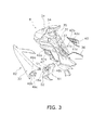
- FIG. 3 is an exploded perspective view of a vehicle body cover of the saddle-ride type vehicle
- FIG. 4 is an enlarged view of a top surface section of the vehicle body cover
- FIG. 5 is a schematic cross-sectional view of the top surface section sectioned along a line V-V in FIG. 4 ;
- FIG. 6 is a side view of the vehicle body cover
- FIG. 7 is an enlarged view of a left lateral surface opening section of the vehicle body cover
- FIG. 8 is a schematic cross-sectional view of the left lateral surface opening section sectioned along a line VIII-VIII in FIG. 7 ;
- FIG. 9 is a right side view of the saddle-ride type vehicle.
- FIG. 10 is a cross-sectional view of first blades and slanted surfaces according to another exemplary embodiment.
- FIG. 11 is a cross-sectional view of first blades and slanted surfaces according to yet another exemplary embodiment.
- FIG. 1 is a side view of a saddle-ride type vehicle 1 according to the exemplary embodiment of the present invention.
- FIG. 2 is a front view of the saddle-ride type vehicle 1.
- the saddle-ride type vehicle 1 is so called a moped.
- a downwardly recessed shape is produced for a section interposed between a seat 7 to be described and a steering section 6 to be described in a longitudinal (back-and-forth) direction of a vehicle body.
- the saddle-ride type vehicle 1 includes a front wheel 2, a rear wheel 3, a drive unit 4, a vehicle body frame 5, the steering unit 6, the seat 7, a vehicle body cover 8 and the like.
- the drive unit 4 is longitudinally disposed between the front wheel 2 and the rear wheel 3 while being supported by the vehicle body frame 5.
- the drive unit 4 includes an engine 11 and a transmission 12.
- the engine 11 is a water-cooled engine including a cylinder unit 13 and a crankcase 14.
- the cylinder unit 13 is disposed on the front side of the crankcase 14.
- the cylinder unit 13 is disposed at a slanted posture for positioning the front portion thereof higher than the rear portion thereof.
- a radiator 15 is disposed forwards of the cylinder unit 13.
- the transmission 12 is integrally disposed behind the crankcase 14.
- the transmission 12 is configured to transmit the drive force from the engine 11 to the rear wheel 3 through a chain.
- Steps 16 and a change pedal 17 are disposed lateral to the transmission 12. A rider puts his/her feet on the steps 16 and shifts up/down gears of the transmission 12 by operating the change pedal 17 with his/her foot.
- the vehicle body frame 5 includes a head pipe 21, a main frame 22 and a rear frame 23.
- the head pipe 21 supports the steering unit 6 for allowing it to rotate.
- the head pipe 21 supports a front fork 24 to be described for allowing it to rotate.
- the main frame 22 corresponds to "a frame unit" of the present invention.
- the main frame 22 is connected to the head pipe 21 while being extended therefrom obliquely rearwards and downwards.
- the main frame 22 is disposed over the drive unit 4.
- a rear arm 25 is pivotably attached to the rear portion of the main frame 22 through a bracket (not illustrated in the figure).
- the rear arm 25 supports the rear wheel 3 for allowing it to rotate.
- the rear frame 23 is connected to the main frame 22 while being extended therefrom obliquely rearwards and upwards.
- the rear frame 23 is disposed over the rear wheel 3.
- the seat 7 is disposed over the rear frame 23 while being supported by the rear frame 23.
- the steering unit 6 includes the front fork 24 and a handle 26.
- the front fork 24 supports the front wheel 2 for allowing it to rotate.
- the front fork 24 includes a pair of front suspensions 27, a bracket 28 and a steering shaft 29.
- the front suspensions 27 are disposed away from each other in the transverse direction of the vehicle.
- the front suspensions 27 support the front wheel 2 for allowing it to rotate.
- the tops of the front suspensions 27 are attached to the bracket 28.
- the bracket 28 is attached to the bottom of the steering shaft 29.
- the steering shaft 29 is rotatably inserted into the head pipe 21.
- the handle 26 is coupled to the top of the steering shaft 29. In other words, the handle 26 is coupled to the top of the front fork 24.
- the seat 7 is disposed over the rear frame 23.
- the seat 7 is disposed rearwards of the steering unit 6 while being separated away from the steering unit 6.
- the vehicle body cover 8 is a resin member covering the vehicle body frame 5.
- the vehicle body cover 8 includes a top surface section 31, a pair of a lateral surface section 32 and a lateral surface section 33 (see FIG. 2 ), and a front surface section 34.
- the top surface section 31 is longitudinally disposed between the steering unit 6 and the seat 7 for covering the top side of the main frame 22.
- the surface of the top surface section 31 is slanted for positioning the front portion thereof higher than the rear portion thereof.
- FIG. 3 illustrates a perspective view of the vehicle body cover 8. It should be noted that FIG. 3 illustrates the vehicle body cover 8 that some components are detached therefrom.
- the top surface section 31 includes a front protruded portion 35 on the front portion thereof.
- the front protruded portion 35 is positioned in the center of the top surface section 31 in the transverse direction of the vehicle.
- the front protruded portion 35 includes an opening 54 for inserting the aforementioned steering shaft 29 therein.
- the top surface section 31 includes a rear bent portion 36 on the rear portion thereof.
- the rear bent portion 36 is upwardly bent.
- the rear bent portion 36 is disposed under the front portion of the seat 7.
- a top surface center portion 37 is longitudinally disposed between the front protruded portion 35 and the rear bent portion 36.
- the top surface center portion 37 is disposed in the center of the top surface section 31 in the transverse direction of the vehicle.
- the top surface center portion 37 is longitudinally extended while being connected to both the front protruded portion 35 and the rear bent portion 36.
- the aforementioned main frame 22 is disposed under the top surface center portion 37.
- FIG. 4 illustrates an enlarged partial top view of the top surface section 31.
- a left top surface opening portion 38 and a right top surface opening portion 39 are disposed on the both lateral sides of the top surface center portion 37.
- the left and right top surface opening portions 38 and 39 are separated away from each other in the transverse direction of the vehicle.
- the structure of the left top surface opening portion 38 is bilaterally symmetrical to that of the right top surface opening portion 39.
- the structure of the left top surface opening portion 38 will be hereinafter explained.
- FIG. 5 is a schematic cross-sectional view of the left top surface opening portion 38.
- the left top surface opening portion 38 includes a plurality of slanted surfaces 41a to 41c and a plurality of first blades 42a to 42c.
- the slanted surfaces 41a to 41c are slanted in the same direction as the surface of the top surface section 31.
- each of the slanted surfaces 41a to 41c is slanted for positioning the front portion thereof higher than the rear portion thereof.
- the slanted surfaces 41a to 41c are disposed away from each other at predetermined intervals in the longitudinal direction of the vehicle.
- Two pairs of adjacent slanted surfaces among the slanted surfaces 41a to 41c form air paths 44a and 44b communicating with the inside of the vehicle body cover 8.
- the air path 44a is formed by the slanted surfaces 41a and 41b.
- the air path 44b is formed by the slanted surfaces 41b and 41c.
- each slanted surface 41a to 41c a given one is positioned higher than the other/others disposed rearwards of the given one.
- the bottom end of each slanted surface is disposed for vertically (up-and-down directionally) overlapping with the slanted surface backwardly adjacent thereto.
- the bottom end of the forefront slanted surface 41a is disposed for vertically overlapping with the slanted surface 41b positioned rearwards thereof.
- the bottom end of the slanted surface 41b is disposed for vertically overlapping with the slanted surface 41c positioned rearwards thereof.
- the bottom end of the forefront slanted surface 41a is positioned higher than the bottom end of the slanted surface 41b positioned rearwards thereof.
- the bottom end of the slanted surface 41a is positioned lower than the top end of the first blade 42b positioned rearwards thereof.
- the bottom end of the slanted surface 41b is positioned higher than the bottom end of the slanted surface 41c positioned rearwards thereof.
- the bottom end of the slanted surface 41b is positioned lower than the top end of the first blade 42c positioned rearwards thereof.
- Each of the first blades 42a to 42c is protruded from a corresponding one of the slanted surfaces 41a to 41c.
- Each of the first blades 42a to 42c is connected to the top end of a corresponding one of the slanted surfaces 41a to 41c while being protruded therefrom to the rearward.
- Each of the first blades 42a to 42c is backwardly extended over a corresponding one of the slanted surfaces 41a to 41c.
- the first blades 42a to 42c are disposed for blocking the air flowing along the slanted surfaces 41a to 41c through the air paths 44a and 44b. It should be noted that each of the first blades 42a to 42c includes a first portion and a second portion.
- the first portion is extended rearwards from each of the slanted surfaces 41a to 41c, whereas the second portion is extended forwards from the rear end of the first portion.
- the first blade 42b includes a first portion 421 and a second portion 422.
- the first portion 421 is extended rearwards from the slanted surface 41b, whereas the second portion 422 is extended forwards from the rear end of the first portion 421.
- the structures of the first blades 42a and 42c are roughly the same as the structure of the first blade 42b.
- a given one is positioned higher than the other/others disposed rearwards of the given one.
- each of the first blades 42a to 42c is slanted with respect to the longitudinal direction of the vehicle for positioning the transversely outward end thereof forwards of the transversely inward end thereof, as illustrated in FIG. 4 .
- each of the first blades 42a to 42c is slanted with respect to the longitudinal direction of the vehicle for positioning the rear portion thereof closer to the vehicle body center in the transverse direction of the vehicle (see a dashed dotted line C1) than the front portion thereof to be.
- transversely inward refers to a direction getting closer to the vehicle body center C1 in the transverse direction of the vehicle.
- the term "transversely outward” refers to a direction separated away from the vehicle body center C1 in the transverse direction of the vehicle.
- a given one has a transverse dimension greater than that of the other/others disposed rearwards of the given one.
- the first blades 42a to 42c are partially recessed.
- the rear side blades of the first blades 42a to 42c i.e., the first blades 42b and 42c have recesses 43b and 43c on the front ends thereof, as illustrated in FIGS. 4 and 5 .
- Each of the recesses 43b and 43c is recessed rearwards.
- the recess 43b is disposed closer to the transversely outward end than to the transversely inward end in the first blade 42b, whereas the recess 43c is disposed closer to the transversely outward end than to the transversely inward end in the first blade 42c.
- the air path 44a communicates with the outer space through the recess 43b, whereas the air path 44b communicates with the outer space through the recess 43c.
- each of the recesses 43b and 43c i.e., the outlet of each of the air paths 44a and 44b to the outside, is disposed closer to the transversely outward end than to the transversely inward end in the slanted surfaces 41a to 41c.
- the rear end of the first blade 42a is positioned forwards of the rear end of the recess 43b.
- the rear end of the first blade 42b is positioned forwards of the rear end of the recess 43c.
- the rear end of the first blade 42a is positioned forwards of the rear edge of the outlet of the air path 44a
- the rear end of the first blade 42b is positioned forwards of the rear edge of the outlet of the air path 44b.
- a part of the first blades 42a to 42c and a part of the slanted surfaces 41a to 41c are produced as individual components separated from the remaining part of the top surface section 31 (hereinafter referred to as "the main body of the top surface section 31").
- a component 40 including the rear side first blades 42b and 42c, a part of the slanted surface 41b, and the slanted surface 41c, is provided as an individual component separated from the main body of the top surface section 31.
- the component 40 is produced as an individual component separated from the main body of the top surface section 31 and includes a part of the plural first blades 42a to 42c and the plural slanted surfaces 41a to 41c.
- the component 40 is attached to the main body of the top surface section 31 while being disposed over the main body of the top surface section 31.
- the component 40 includes the first blades 42b and 42c provided with the aforementioned recesses 43b and 43c.
- the slanted surface 41b is formed by a top portion 411 included in the component 40 and a bottom portion 412 included in the main body of the top surface section 31, as illustrated in FIG. 5 .
- the component 40 is fixed to the main body of the top surface section 31 by fixation means such as screws or a fitting structure.
- a pair of the lateral surface sections 32 and 33 (hereinafter referred to as "a right lateral surface section 33" and "a left lateral surface section 32") at least partially covers the both lateral sides of the drive unit 4.
- the left lateral surface section 32 covers the left sides of the cylinder unit 13 of the engine 11, the steering unit 6, the radiator 15 and the like.
- the right lateral surface section 33 covers the right sides of the cylinder unit 13 of the engine 11, the steering unit 6, the radiator 15 and the like.
- FIG. 6 illustrates a side view of the vehicle body cover 8. In the side view, the front portion of the left lateral surface section 32 has a curved shape recessed rearwards.
- the top portion of the left lateral surface section 32 is connected to both the top surface section 31 and the front surface section 34. Further, the left lateral surface section 32 includes an opening 45 and a left lateral surface opening section 46.
- the opening 45 communicates with the inside of the vehicle body cover 8. In the side view of the vehicle body, the opening 45 is positioned lower than the aforementioned air paths 44a and 44b.
- the cylinder unit 13 of the engine 11 is positioned inwards of the opening 45.
- FIG. 7 illustrates an enlarged view of the left lateral surface opening section 46.
- the left lateral surface opening section 46 includes a guide plate 47, second blades 48a and 48b and third blades 49a to 49c.
- FIG. 8 illustrates a schematic cross-sectional view of the left lateral surface opening section 46 sectioned along a line VIII-VIII in FIG. 7 .
- the guide plate 47 is disposed inwards of the opening 45.
- the guide plate 47 is disposed inwards of the left lateral surface section 32 while being opposed to the opening 45.
- the bottom and rear portions of the guide plate 47 are connected to the left lateral surface section 32.
- the top and front portions of the guide plate 47 are opened in the inward of the lateral surface sections 32, while being disposed away from the left lateral surface section 32 at a predetermined interval. Therefore, the air in the inside of the vehicle body cover 8 is allowed to flow from the top and front sides of the guide plate 47 to the outside of the vehicle body cover 8 through the lateral side of the guide plate 47 and the opening 45 (see arrows A2 depicted with dashed two-dotted lines in FIG. 8 ).
- the second blades 48a and 48b are disposed on the outer surface of the guide plate 47 while being laterally protruded therefrom.
- the second blades 48a and 48b are disposed across the opening 45 in the vertical direction.
- the second blades 48a and 48b are plate-like members extended in the vertical direction. Specifically, the second blades 48a and 48b are slanted with respect to the vertical direction for positioning the bottom portion thereof to be positioned forwards of the top portion thereof.
- the third blades 49a to 49c are disposed across the opening 45 in the longitudinal direction. In the side view, the third blades 49a to 49c are disposed for intersecting with the second blades 48a and 48b, while being disposed lateral to the second blades 48a and 48b.
- the third blades 49a to 49c are extended in the longitudinal direction of the vehicle body. Specifically, the third blades 49a to 49c are slanted with respect to the longitudinal direction of the vehicle body for positioning the rear portion thereof higher than the front portion thereof.
- the left lateral surface section 32 includes a guide portion 51 and a protruded portion 52, as illustrated in FIG. 6 .
- the guide portion 51 is disposed rearwards of the opening 45 while being disposed along the rear edge of the opening 45.
- the guide portion 51 is extended from the rear edge of the opening 45 in the transverse direction of the vehicle for guiding the air flowing out of the opening 45 in the transverse direction of the vehicle.
- the protruded portion 52 is positioned lower than the opening 45.
- the protruded portion 52 is protruded away from the vehicle body center to the outward of the vehicle body cover 8 in the transverse direction of the vehicle.
- the protruded portion 52 is positioned at roughly the same height as the aforementioned steps 16 and the aforementioned change pedal 17 (see FIG. 1 ).
- a top surface 52a of the protruded portion 52 is slanted for positioning the rear portion thereof higher than the front portion thereof.
- a bottom surface 52b of the protruded portion 52 is slanted for positioning the rear portion thereof higher than the front portion thereof.
- the bottom surface 52b of the protruded portion 52 is slanted for setting a portion thereof positioned furthest from the vehicle body center to be positioned higher than a portion thereof positioned closer to the vehicle body center in the transverse direction of the vehicle.
- the vehicle body cover 8 includes a first cover component 61 and a second cover component 62.
- the first and second cover components 61 and 62 are produced as separate individual components.
- the left lateral surface section 32 is formed by the first and second cover components 61 and 62. In other words, the left lateral surface section 32 can be divided into the first and second cover components 61 and 62 at the opening 45 as the boundary therebetween.
- the first cover component 61 mainly forms the bottom portion of the left lateral surface section 32.
- the first cover component 61 includes the aforementioned guide plate 47 and the aforementioned second blades 48a and 48b. Further, the first cover component 61 includes a part of the left lateral surface section 32 including the aforementioned guide portion 51, the aforementioned protruded portion 52 and the like.
- the second cover component 62 mainly forms the top portion of the left lateral surface section 32.
- the second cover component 62 includes the aforementioned third blades 49a to 49c and the remaining part of the left lateral surface section 32.
- the front surface section 34 covers the front side of the head pipe 21. As illustrated in FIGS. 2 and 6 , the front surface section 34 includes a pair of apertures 63 and 64. In other words, the apertures 63 and 64 are disposed in the vehicle body cover 8 while being positioned forwards of the air paths 44a and 44b. The apertures 63 and 64 are separated away from each other in the transverse direction of the vehicle while being disposed bilaterally symmetric to each other. Further, the apertures 63 and 64 are disposed closer to the tops of the right and left lateral surface sections 33 and 32. The apertures 63 and 64 are opened to the forward of the vehicle body, while communicating with the inside of the vehicle body cover 8. Further, the vehicle body cover 8 includes an opening 81 in a portion thereof positioned forwards of the radiator 15, as illustrated in FIG. 2 . The opening 81 is positioned rearwards of the front wheel 2.
- the right lateral surface section 33 has roughly the same structure as the left lateral surface section 32. Similarly to the lateral surface section 32, the right lateral surface section 33 includes the guide portion 51 and the protruded portion 52, as illustrated in FIG. 9 . Further, the right lateral surface section 33 includes a mud flap 53.
- the mud flap 53 is downwardly protruded from the bottom surface of the right lateral surface section 33. Specifically, the mud flap 53 is downwardly protruded from the rear portion of the bottom surface of the protruded portion 52. In the side view, the mud flap 53 is positioned forwards of the crankcase 14 of the engine 11. The mud flap 53 is extended to a position lower than the bottom of the engine 11.
- the outside air flows into the inside of the vehicle body cover 8 through the apertures 63 and 64 of the front surface section 34. Further, the outside air flows into the inside of the vehicle body cover 8 through the opening 81 of the vehicle body cover 8. A part of the air flowing into the inside of the vehicle body cover 8 flows to the outside through the air paths 44a and 44b of the top surface section 31. Further, another part of the air flowing into the inside of the vehicle body cover 8 flows downwards and then flows to the outside through the opening 45. While the saddle-ride type vehicle 1 stops, by contrast, the warmed air flows up through the inside of the vehicle body cover 8. The warmed air subsequently flows to the outside through the air paths 44a and 44b of the top surface section 31.
- the saddle-ride type vehicle 1 of the present exemplary embodiment of the present invention has the following features.
- each of the first blades 42a to 42c is disposed for extending rearwards from a corresponding one of the slanted surfaces 41a to 41c. Therefore, the first blades 42a to 42c disturb the air flowing along the slanted surfaces 41a to 41c.
- the warmed air, flowing out of the air paths 44a and 44b, is thereby prevented from easily flowing towards a rider seated rearwards of the top surface section 31.
- the air flowing out of the right top surface opening portion 39 is similar to the air flowing out of the left top surface opening portion 38. It is thus possible to inhibit deterioration of rider's comfortableness.
- the warmed air in the inside of the vehicle body cover 8 is easily discharged to the outside.
- temperature elevation can be inhibited within the inside of the vehicle body cover 8.
- the right lateral surface section 33 has roughly the same structure as that of the left lateral surface section 32. Therefore, the right lateral surface section 33 has roughly the same features as those of the left lateral surface section 32.
- the air in the inside of the vehicle body cover 8 flows through the clearance between the top portion of the guide plate 47 and the left lateral surface section 32, then flows downwards while being guided by the guide plate 47 and the second blades 48a and 48b, and is discharged to the outside through the opening 45 (see the arrows A2 depicted with the dashed two-dotted lines in FIG. 8 ). It is thereby easy to outwardly discharge the air flowing from the above of the opening 45 within the inside of the vehicle body cover 8. Therefore, it is possible to further inhibit temperature elevation of the air flowing out of the air paths 44a and 44b of the top surface section 31. Accordingly, it is possible to further inhibit deterioration of rider's comfortableness.
- the air flowing out of the opening 45 is guided by the guide portion 51 along the transverse direction of the vehicle. Accordingly, the warmed air can be inhibited from flowing towards a rider.
- the air outside the vehicle body cover 8 is guided by the third blades 49a to 49c along a direction different from the direction of the air flowing out of the opening 45. Accordingly, the warmed air flowing out of the opening 45 is diffused by the flow of the outside air guided by the third blades 49a to 49c. Therefore, the warmed air flowing out of the opening 45 is prevented from easily flowing towards a rider.
- the second blades 48a and 48b and the third blades 49a to 49c are respectively included in separate individual components. It is thereby possible to easily produce the aforementioned complexly shaped vehicle body cover.
- the air flowing out of the opening 45 is guided by the top surface 52a of the protruded portion 52.
- the warmed air flowing out of the opening 45 can be thereby inhibited from flowing towards a rider.
- mud splashed from the ground is guided by the bottom surface 52b of the protruded portion 52. The splashed mud is thereby inhibited from attaching to the engine 11 and rider's feet.
- the mud flap 53 is extended to a position lower than the bottom of the engine 11. Therefore, the mud flap 53 can inhibit attachment of mud to the engine 11 and rider's feet.
- the air flowing outside the vehicle body cover 8 is guided by the first blades 42a to 42c. Therefore, the flow of the warmed air flowing out of the air paths 44a and 44b is diffused by the flow of the outside air guided by the first blades 42a to 42c. Accordingly, the warmed air can be inhibited from flowing towards a rider.
- Each of the first blades 42a to 42c is protruded rearwards from the top end of a corresponding one of the slanted surfaces 41a to 41c. Therefore, the airflow along the slanted surfaces 41a to 41c can be more effectively disturbed by the first blades 42a to 42c. Accordingly, the warmed air flowing out of the air paths 44a and 44b can be further prevented from easily flowing towards a rider seated rearwards of the vehicle body cover 8.
- the warmed air flowing out of the air paths 44a and 44b is more effectively diffused by the flow of the outside air guided by the first blades 42a to 42c. Accordingly, the warmed air can be further inhibited from flowing towards a rider.
- the recesses 43b and 43c are disposed in higher positions within the air paths 44a and 44b. Therefore, the warmed air easily gathers in the recesses 43b and 43c. Further, the recesses 43b and 43c are disposed closer to the transversely outward end than to the transversely inward end in the slanted surfaces 41a to 41c. Therefore, it is further possible to inhibit the warmed air, flowing out of the recesses 43b and 43c through the air paths 44a and 44b, from flowing towards a rider.
- the present invention may not be limited to the aforementioned exemplary embodiment and a variety of changes can be made for the present invention without departing from the scope of the present invention.
- the detailed shape of the vehicle body cover 8 may not be limited to the aforementioned shape.
- the components forming the vehicle body cover 8 may not be necessarily divided in the aforementioned configuration.
- the number of the first blades 42a to 42c and the number of the slanted surfaces 41a to 41c may not be necessarily limited to the aforementioned configurations.
- only one first blade may be provided.
- the first blade is extended rearwards from a slanted surface, which is positioned forwards of an air path, of a plurality of slanted surfaces.
- the first blade may be extended rearwards from either the slanted surface 41a positioned forwards of the air path 44a or the slanted surface 41b positioned forwards of the air path 44b.
- the number of the second blades 48a and 48b and the number of the third blades 49a to 49c may not be necessarily limited to the aforementioned configurations.
- the apertures 63 and 64 may be disposed in any suitable portions of the vehicle body cover 8 different from the front surface section 34 as long as they are disposed in the vehicle body cover 8 and positioned forwards of the air paths 44a and 44b.
- the mud flap 53 may not be necessarily provided to the right lateral surface section 33, and may be provided to the left lateral surface section 32.
- the main frame 22 is disposed over the drive unit 4.
- Another member may be herein interposed between the main frame 22 and the drive unit 4.
- the frame unit is disposed over the drive unit in the present invention.
- Another member may be herein interposed between the frame unit and the drive unit.
- the component 40 including the first blades 42b and 42c and the slanted surfaces 41b and 41c, is provided as an individual component separated from the remaining part of the top surface section 31.
- the first blades 42b and 42c and the slanted surfaces 41b and 41c may be integrally formed with the main body of the top surface section 31 similarly to the other first blade 42a and the other slanted surface 41a.
- each of the first blades 42a to 42c is integrally formed with a corresponding one of the slanted surfaces 41a to 41c.
- each of the first blades 42a to 42c may be provided as an individual component separated from a corresponding one of the slanted surfaces 41a to 41c.
- the first blade 42b may be disposed separately away from the slanted surface 41b, whereas the first blade 42c may be disposed separately away from the slanted surface 41c.
- each of the first blades 42a to 42c includes a first portion and a second portion.
- the first portion is extended rearwards from each of the slanted surfaces 41a to 41c, whereas the second portion is extended forwards from the rear end of the first portion.
- each of the first blades 42a to 42c is only required to include at least the first portion.
- each of the first blades 42b and 42c may be formed by the first portion 421 without including a second portion.
- the first blade 42c of the plural first blades 42a to 42c may not be necessarily provided. In other words, it is not necessary to provide a blade extended rearwards from rearmost one of the slanted surfaces forming air paths.
- the present invention has been described in connection to a moped. However, the invention can be applied to other straddle-type vehicles, such as trikes or squads.
Landscapes
- Engineering & Computer Science (AREA)
- Mechanical Engineering (AREA)
- Automatic Cycles, And Cycles In General (AREA)
Abstract
Description
- The present invention relates to a saddle-ride type vehicle.
- A vehicle body cover is disposed between a handle and a seat in some of the well-known saddle-ride type vehicles such as a motorcycle described in Japan Laid-open Patent Application Publication No.
JP-A-2004-291700 - In the motorcycles of the aforementioned type, the engine is disposed under the vehicle body cover. The air warmed by the heat of the engine flows out of the opening section of the vehicle body cover while the motorcycle travels or stops. The warmed air, blowing out of the opening section, flows upwards and rearwards while being guided by the fins. Simply put, the warmed air, blowing out of the opening section, tends to flow towards a rider sitting on the seat. Therefore, the warmed air may deteriorate comfortableness of the rider.
It is an object of the present invention to inhibit rider's comfortableness from being deteriorated by the warmed air flowing out of the vehicle body cover in a saddle-ride type vehicle.
This object is solved by the features of claim 1.
Further improvements are laid down in the sub-claims. - A saddle-ride type vehicle according to a first aspect of the present invention includes a frame unit supporting a steering unit and a seat disposed rearwards of the steering unit,
a drive unit, disposed between the steering unit and the seat, and
a vehicle body cover including a top surface section and a lateral surface section. The top surface section is disposed between the steering unit and the seat for covering a top side of the frame unit. The lateral surface section at least partially covers a lateral side of the drive unit. The top surface section of the vehicle body cover includes a plurality of slanted surfaces. Each of the slanted surfaces is slanted for positioning a front portion thereof higher than a rear portion thereof. The slanted surfaces are disposed away from each other along a longitudinal direction of a vehicle body. The slanted surfaces form a single or plurality of air paths between every adjacent two of the slanted surfaces. The single or plurality of the air paths communicate with an inner space enclosed by the vehicle body cover.
The top surface section of the vehicle body cover includes a first blade. The first blade is extended rearwards over the slanted surface. - A saddle-ride type vehicle according to a second aspect of the present invention includes a front wheel, a rear wheel, the drive unit, the steering unit, a head pipe, the frame unit, the seat and the vehicle body cover. The drive unit is disposed between the front wheel and the rear wheel. The steering unit includes a front fork and a handle. The front fork supports the front wheel for allowing the front wheel to rotate. The handle is coupled to a top of the front fork. The head pipe supports the steering unit for allowing the steering unit to rotate. The frame unit is connected to the head pipe while being disposed over the drive unit.
- A saddle-ride type vehicle according to a third aspect of the present invention relates to the saddle-ride type vehicle according to the first aspect of the preset invention. In the saddle-ride type vehicle, the lateral surface section includes an opening. The opening is positioned lower than the single or plurality of air paths in a side view of the vehicle body, while communicating with the inner space enclosed by the vehicle body cover.
- A saddle-ride type vehicle according to a fourth aspect of the present invention relates to the saddle-ride type vehicle according to the third aspect of the present invention. In the saddle-ride type vehicle, the vehicle body cover includes a guide plate and a second blade. The guide plate is disposed inwards of the opening. The second blade is disposed on an outer surface of the guide plate, while being extended in a vertical direction. A bottom portion of the guide plate is connected to the lateral surface section. A top portion of the guide plate is disposed away from the lateral surface section.
- A saddle-ride type vehicle according to a fifth aspect of the present invention relates to the saddle-ride type vehicle according to the third aspect of the present invention. In the saddle-ride type vehicle, the lateral surface section includes a guide portion. The guide portion is disposed rearwards of the opening, while being extended along a transverse direction of the vehicle body.
- A saddle-ride type vehicle according to a sixth aspect of the present invention relates to the saddle-ride type vehicle according to the third aspect of the present invention. In the saddle-ride type vehicle, the vehicle body cover includes a third blade. The third blade is disposed across the opening while being extended along the longitudinal direction of the vehicle body.
- A saddle-ride type vehicle according to a seventh aspect of the present invention relates to the saddle-ride type vehicle according to the third aspect of the present invention. In the saddle-ride type vehicle, the vehicle body cover includes a first cover component and a second cover component. The second cover component is produced as an individual component separated from the first component. The first cover component includes a guide plate, a second blade and a part of the lateral surface section. The guide plate is disposed inwards of the lateral surface section while being opposed to the opening. A bottom portion of the guide plate is connected to the lateral surface section, whereas a top portion of the guide plate is disposed away from the lateral surface section. The second blade is disposed along a surface of the guide plate, while being extended in a vertical direction. The second cover component includes the third blade and another part of the lateral surface section.
- A saddle-ride type vehicle according to a eighth aspect of the present invention relates to the saddle-ride type vehicle according to the third aspect of the present invention. In the saddle-ride type vehicle, the lateral surface section includes a protruded portion. The protruded portion is positioned lower than the opening. The protruded portion is protruded away from a vehicle body center to the outward of the vehicle body cover in a transverse direction of the vehicle body. A bottom surface of the protruded portion is slanted for positioning a rear portion thereof higher than a front portion thereof.
- A saddle-ride type vehicle according to an ninth aspect of the present invention relates to the saddle-ride type vehicle according to the first aspect of the present invention. In the saddle-ride type vehicle, the vehicle body cover includes an aperture in a part thereof positioned forwards of the single or plurality of the air paths. The aperture is opened to the forward of the vehicle body, while communicating with the inner space enclosed by the vehicle body cover.
- A saddle-ride type vehicle according to a tenth aspect of the present invention relates to the saddle-ride type vehicle according to the first aspect of the present invention. In the saddle-ride type vehicle, the lateral surface section includes a mud flap. The mud flap is protruded downwards from a bottom surface of the lateral surface section while being extended to a position lower than a bottom portion of the drive unit.
- A saddle-ride type vehicle according to a eleventh aspect of the present invention relates to the saddle-ride type vehicle according to the first aspect of the present invention. In the saddle-ride type vehicle, the first blade is slanted with respect to the longitudinal direction of the vehicle body for positioning a transversely outward end thereof forwards of a transversely inward end thereof.
- A saddle-ride type vehicle according to an twelfth aspect of the present invention relates to the saddle-ride type vehicle according to the first aspect of the present invention. In the saddle-ride type vehicle, the first blade is protruded rearwards from a top end of the slanted surface.
- A saddle-ride type vehicle according to a thirteenth aspect of the present invention relates to the saddle-ride type vehicle according to the first aspect of the present invention. The top surface section of the vehicle body cover further includes a single or plurality of blades identical to the first blade. Each of the single or plurality of blades is extended rearwards over each of the slanted surfaces on a one-to-one basis. A given one of the first blade and the blade/blades identical thereto is positioned higher than the other or others of the first blade and the blade/blades identical thereto disposed rearwards of the given one of the first blade and the blade/blades identical thereto.
- A saddle-ride type vehicle according to a fourteenth aspect of the present invention relates to the saddle-ride type vehicle according to the first aspect of the present invention. In the saddle-ride type vehicle, an outlet of each of the single or plurality of the air paths to the outside of the vehicle body cover is disposed closer to transversely outward ends of the slanted surfaces than to transversely inward ends of the slanted surfaces.
- According to the saddle-ride type vehicle of the first aspect of the present invention, the air in the inner space enclosed by the vehicle body cover flows to the outside through the air path/paths. Each of the slanted surfaces forming the air path/paths is slanted for positioning the front portion thereof higher than the rear portion thereof. Therefore, the air flows upwards and forwards along the slanted surfaces. The first blade is extended rearwards from a given one of the slanted surfaces. Therefore, the airflow along the slanted surfaces is disturbed by the first blade. Accordingly, the warmed air flowing out of the air path/paths can be prevented from easily flowing towards a rider seating rearwards of the vehicle body cover. Consequently, it is possible to inhibit rider's comfortableness from being deteriorated by the warmed air flowing out of the vehicle body cover.
- According to the saddle-ride type vehicle of the third aspect of the present invention, air flows out of the opening of the lateral surface section as well as the air path/paths of the top surface section in the vehicle body cover. Therefore, the warmed air in the inner space enclosed by the vehicle body cover is easily discharged to the outside. Accordingly, it is possible to enhance a ventilation performance within the inner space enclosed by the vehicle body cover.
- According to the saddle-ride type vehicle of the fourth aspect of the present invention, the air in the inner space enclosed by the vehicle body cover flows through the clearance between the top portion of the guide plate and the lateral surface section, then flows downwards while being guided by the guide plate and the second blade, and is discharged to the outside through the opening. Therefore, it is easy to outwardly discharge the air flowing from the above of the opening within the inner space enclosed by the vehicle body cover. Therefore, the warmed air, remaining without being discharged from the air path/paths of the top surface section, can be easily discharged to the outside through the opening.
- According to the saddle-ride type vehicle of the fifth aspect of the present invention, the air flowing out of the opening is guided by the guide portion in the transverse direction of the vehicle body. Accordingly, the warmed air can be inhibited from flowing towards a rider.
- According to the saddle-ride type vehicle of the sixth aspect of the present invention, the air flowing outside the vehicle body cover is guided by the third blade in a direction different from the direction of the air flowing out of the opening. Accordingly, it is possible to diffuse the warmed air flowing out of the opening. Therefore, the warmed air can be inhibited from flowing towards a rider.
- According to the saddle-ride type vehicle of the seventh aspect of the present invention, the second blade and the third blade are included in separate individual components. Therefore, it is possible to easily form the complexly shaped vehicle body cover including the blades.
- According to the saddle-ride type vehicle of the eighth aspect of the present invention, the air flowing out of the opening is guided by the top surface of the protruded portion. Accordingly, the warmed air flowing out of the opening can be inhibited from flowing towards a rider. Further, mud splashed from the ground is guided by the bottom surface of the protruded portion. Therefore, it is possible to inhibit mud from attaching to the vehicle body or rider's feet.
- According to the saddle-ride type vehicle of the ninth aspect of the present invention, air flows into the inner space enclosed by the vehicle body cover through the aperture. A part of the air flowing into the inner space flows to the outside through the air path/paths of the top surface section. On the other hand, another part of the air flowing into the inner space flows downwards and then flows to the outside through the opening. Accordingly, it is possible to further enhance a ventilation performance within the inner space enclosed by the vehicle body cover.
- According to the saddle-ride type vehicle of the tenth aspect of the present invention, the mud flap can inhibit mud from attaching to the drive unit.
- According to the saddle-ride type vehicle of the eleventh aspect of the present invention, the air flowing outside the vehicle body cover can be guided by the first blade. Therefore, the flow of the warmed air flowing out of the air path/paths can be diffused by the flow of the outside air guided by the first blade. Accordingly, the warmed air can be inhibited from flowing toward a rider.
- According to the saddle-ride type vehicle of the twelfth aspect of the present invention, the airflow along the slanted surfaces can be more effectively disturbed by the first blade. Accordingly, the warmed air flowing out of the air path/paths can be further prevented from easily flowing towards a rider seated rearwards of the vehicle body cover.
- According to the saddle-ride type vehicle of the thirteenth aspect of the present invention, the flow of the warmed air flowing out of the air paths is more effectively diffused by the flow of the outside air guided by the first blade and the blade/blades. Accordingly, the warmed air can be further inhibited from flowing towards a rider.
- According to the saddle-ride type vehicle of the fourteenth aspect of the present invention, the outlet of each of the single or plurality of the air paths to the outside of the vehicle body cover is disposed closer to transversely outward ends of the slanted surfaces than to transversely inward ends of the slanted surfaces. Therefore, the warmed air flowing out of the air path/paths can be further prevented from easily flowing towards a rider seated rearwards of the vehicle body cover.
- Referring now to the attached drawings which form a part of this original disclosure:
-
FIG. 1 is a left side view of a saddle-ride type vehicle according to an exemplary embodiment of the present invention; -
FIG. 2 is a front view of the saddle-ride type vehicle; -
FIG. 3 is an exploded perspective view of a vehicle body cover of the saddle-ride type vehicle; -
FIG. 4 is an enlarged view of a top surface section of the vehicle body cover; -
FIG. 5 is a schematic cross-sectional view of the top surface section sectioned along a line V-V inFIG. 4 ; -
FIG. 6 is a side view of the vehicle body cover; -
FIG. 7 is an enlarged view of a left lateral surface opening section of the vehicle body cover; -
FIG. 8 is a schematic cross-sectional view of the left lateral surface opening section sectioned along a line VIII-VIII inFIG. 7 ; -
FIG. 9 is a right side view of the saddle-ride type vehicle; -
FIG. 10 is a cross-sectional view of first blades and slanted surfaces according to another exemplary embodiment; and -
FIG. 11 is a cross-sectional view of first blades and slanted surfaces according to yet another exemplary embodiment. - An exemplary embodiment of the present invention will be hereinafter explained with reference to figures.
FIG. 1 is a side view of a saddle-ride type vehicle 1 according to the exemplary embodiment of the present invention.FIG. 2 is a front view of the saddle-ride type vehicle 1. The saddle-ride type vehicle 1 is so called a moped. In the saddle-ride type vehicle 1, a downwardly recessed shape is produced for a section interposed between aseat 7 to be described and asteering section 6 to be described in a longitudinal (back-and-forth) direction of a vehicle body. It should be noted that directional terms such as "front", "rear", "right" and "left" and their related terms refer to directions seen from a rider seated on theseat 7 of the saddle-ride type vehicle 1 in the following explanation unless otherwise specified. Further, the term "lateral" and its related terms refer to a direction separated away from the vehicle body center in a transverse (width/right-and-left) direction of the vehicle. As illustrated inFIG. 1 , the saddle-ride type vehicle 1 includes afront wheel 2, arear wheel 3, a drive unit 4, a vehicle body frame 5, thesteering unit 6, theseat 7, avehicle body cover 8 and the like. - The drive unit 4 is longitudinally disposed between the
front wheel 2 and therear wheel 3 while being supported by the vehicle body frame 5. The drive unit 4 includes anengine 11 and atransmission 12. Theengine 11 is a water-cooled engine including acylinder unit 13 and acrankcase 14. Thecylinder unit 13 is disposed on the front side of thecrankcase 14. Thecylinder unit 13 is disposed at a slanted posture for positioning the front portion thereof higher than the rear portion thereof. Further, aradiator 15 is disposed forwards of thecylinder unit 13. Thetransmission 12 is integrally disposed behind thecrankcase 14. Thetransmission 12 is configured to transmit the drive force from theengine 11 to therear wheel 3 through a chain. Steps 16 and a change pedal 17 are disposed lateral to thetransmission 12. A rider puts his/her feet on the steps 16 and shifts up/down gears of thetransmission 12 by operating the change pedal 17 with his/her foot. - The vehicle body frame 5 includes a
head pipe 21, amain frame 22 and arear frame 23. Thehead pipe 21 supports thesteering unit 6 for allowing it to rotate. Specifically, thehead pipe 21 supports afront fork 24 to be described for allowing it to rotate. Themain frame 22 corresponds to "a frame unit" of the present invention. Themain frame 22 is connected to thehead pipe 21 while being extended therefrom obliquely rearwards and downwards. Themain frame 22 is disposed over the drive unit 4. Arear arm 25 is pivotably attached to the rear portion of themain frame 22 through a bracket (not illustrated in the figure). Therear arm 25 supports therear wheel 3 for allowing it to rotate. Therear frame 23 is connected to themain frame 22 while being extended therefrom obliquely rearwards and upwards. Therear frame 23 is disposed over therear wheel 3. Theseat 7 is disposed over therear frame 23 while being supported by therear frame 23. - The
steering unit 6 includes thefront fork 24 and ahandle 26. Thefront fork 24 supports thefront wheel 2 for allowing it to rotate. Specifically, thefront fork 24 includes a pair offront suspensions 27, abracket 28 and a steeringshaft 29. Thefront suspensions 27 are disposed away from each other in the transverse direction of the vehicle. Thefront suspensions 27 support thefront wheel 2 for allowing it to rotate. The tops of thefront suspensions 27 are attached to thebracket 28. Thebracket 28 is attached to the bottom of the steeringshaft 29. The steeringshaft 29 is rotatably inserted into thehead pipe 21. Thehandle 26 is coupled to the top of the steeringshaft 29. In other words, thehandle 26 is coupled to the top of thefront fork 24. - The
seat 7 is disposed over therear frame 23. Theseat 7 is disposed rearwards of thesteering unit 6 while being separated away from thesteering unit 6. - The
vehicle body cover 8 is a resin member covering the vehicle body frame 5. Thevehicle body cover 8 includes atop surface section 31, a pair of alateral surface section 32 and a lateral surface section 33 (seeFIG. 2 ), and afront surface section 34. - The
top surface section 31 is longitudinally disposed between thesteering unit 6 and theseat 7 for covering the top side of themain frame 22. The surface of thetop surface section 31 is slanted for positioning the front portion thereof higher than the rear portion thereof.FIG. 3 illustrates a perspective view of thevehicle body cover 8. It should be noted thatFIG. 3 illustrates thevehicle body cover 8 that some components are detached therefrom. As illustrated inFIG. 3 , thetop surface section 31 includes a front protrudedportion 35 on the front portion thereof. The front protrudedportion 35 is positioned in the center of thetop surface section 31 in the transverse direction of the vehicle. The front protrudedportion 35 includes anopening 54 for inserting theaforementioned steering shaft 29 therein. Thetop surface section 31 includes a rearbent portion 36 on the rear portion thereof. The rearbent portion 36 is upwardly bent. The rearbent portion 36 is disposed under the front portion of theseat 7. A topsurface center portion 37 is longitudinally disposed between the front protrudedportion 35 and the rearbent portion 36. The topsurface center portion 37 is disposed in the center of thetop surface section 31 in the transverse direction of the vehicle. The topsurface center portion 37 is longitudinally extended while being connected to both the front protrudedportion 35 and the rearbent portion 36. The aforementionedmain frame 22 is disposed under the topsurface center portion 37.FIG. 4 illustrates an enlarged partial top view of thetop surface section 31. In thetop surface section 31, a left topsurface opening portion 38 and a right topsurface opening portion 39 are disposed on the both lateral sides of the topsurface center portion 37. The left and right topsurface opening portions surface opening portion 38 is bilaterally symmetrical to that of the right topsurface opening portion 39. The structure of the left topsurface opening portion 38 will be hereinafter explained. -
FIG. 5 is a schematic cross-sectional view of the left topsurface opening portion 38. The left topsurface opening portion 38 includes a plurality of slantedsurfaces 41a to 41c and a plurality offirst blades 42a to 42c. - The slanted surfaces 41a to 41c are slanted in the same direction as the surface of the
top surface section 31. In other words, each of theslanted surfaces 41a to 41c is slanted for positioning the front portion thereof higher than the rear portion thereof. The slanted surfaces 41a to 41c are disposed away from each other at predetermined intervals in the longitudinal direction of the vehicle. Two pairs of adjacent slanted surfaces among theslanted surfaces 41a to 41cform air paths vehicle body cover 8. Specifically, theair path 44a is formed by theslanted surfaces air path 44b is formed by the slantedsurfaces slanted surfaces 41a to 41c, a given one is positioned higher than the other/others disposed rearwards of the given one. The bottom end of each slanted surface is disposed for vertically (up-and-down directionally) overlapping with the slanted surface backwardly adjacent thereto. Specifically, the bottom end of the forefront slantedsurface 41a is disposed for vertically overlapping with theslanted surface 41b positioned rearwards thereof. Further, the bottom end of the slantedsurface 41b is disposed for vertically overlapping with the slantedsurface 41c positioned rearwards thereof. In other words, the bottom end of the forefront slantedsurface 41a is positioned higher than the bottom end of the slantedsurface 41b positioned rearwards thereof. In addition, the bottom end of the slantedsurface 41a is positioned lower than the top end of thefirst blade 42b positioned rearwards thereof. Further, the bottom end of the slantedsurface 41b is positioned higher than the bottom end of the slantedsurface 41c positioned rearwards thereof. In addition, the bottom end of the slantedsurface 41b is positioned lower than the top end of thefirst blade 42c positioned rearwards thereof. - Each of the
first blades 42a to 42c is protruded from a corresponding one of theslanted surfaces 41a to 41c. Each of thefirst blades 42a to 42c is connected to the top end of a corresponding one of theslanted surfaces 41a to 41c while being protruded therefrom to the rearward. Each of thefirst blades 42a to 42c is backwardly extended over a corresponding one of theslanted surfaces 41a to 41c. In other words, thefirst blades 42a to 42c are disposed for blocking the air flowing along theslanted surfaces 41a to 41c through theair paths first blades 42a to 42c includes a first portion and a second portion. The first portion is extended rearwards from each of theslanted surfaces 41a to 41c, whereas the second portion is extended forwards from the rear end of the first portion. For example, thefirst blade 42b includes afirst portion 421 and asecond portion 422. Thefirst portion 421 is extended rearwards from the slantedsurface 41b, whereas thesecond portion 422 is extended forwards from the rear end of thefirst portion 421. The structures of thefirst blades first blade 42b. As to thefirst blades 42a to 42c, a given one is positioned higher than the other/others disposed rearwards of the given one. Further, each of thefirst blades 42a to 42c is slanted with respect to the longitudinal direction of the vehicle for positioning the transversely outward end thereof forwards of the transversely inward end thereof, as illustrated inFIG. 4 . In other words, each of thefirst blades 42a to 42c is slanted with respect to the longitudinal direction of the vehicle for positioning the rear portion thereof closer to the vehicle body center in the transverse direction of the vehicle (see a dashed dotted line C1) than the front portion thereof to be. It should be noted that the term "transversely inward" refers to a direction getting closer to the vehicle body center C1 in the transverse direction of the vehicle. On the other hand, the term "transversely outward" refers to a direction separated away from the vehicle body center C1 in the transverse direction of the vehicle. As to thefirst blades 42a to 42c, a given one has a transverse dimension greater than that of the other/others disposed rearwards of the given one. Further, thefirst blades 42a to 42c are partially recessed. Specifically, the rear side blades of thefirst blades 42a to 42c, i.e., thefirst blades recesses FIGS. 4 and5 . Each of therecesses recess 43b is disposed closer to the transversely outward end than to the transversely inward end in thefirst blade 42b, whereas therecess 43c is disposed closer to the transversely outward end than to the transversely inward end in thefirst blade 42c. Theair path 44a communicates with the outer space through therecess 43b, whereas theair path 44b communicates with the outer space through therecess 43c. In other words, each of therecesses air paths slanted surfaces 41a to 41c. The rear end of thefirst blade 42a is positioned forwards of the rear end of therecess 43b. Similarly, the rear end of thefirst blade 42b is positioned forwards of the rear end of therecess 43c. In other words, the rear end of thefirst blade 42a is positioned forwards of the rear edge of the outlet of theair path 44a, whereas the rear end of thefirst blade 42b is positioned forwards of the rear edge of the outlet of theair path 44b. - As illustrated in
FIG. 3 , a part of thefirst blades 42a to 42c and a part of theslanted surfaces 41a to 41c are produced as individual components separated from the remaining part of the top surface section 31 (hereinafter referred to as "the main body of thetop surface section 31"). Specifically, acomponent 40, including the rear sidefirst blades surface 41b, and the slantedsurface 41c, is provided as an individual component separated from the main body of thetop surface section 31. In other words, thecomponent 40 is produced as an individual component separated from the main body of thetop surface section 31 and includes a part of the pluralfirst blades 42a to 42c and the pluralslanted surfaces 41a to 41c. Thecomponent 40 is attached to the main body of thetop surface section 31 while being disposed over the main body of thetop surface section 31. Specifically, thecomponent 40 includes thefirst blades aforementioned recesses slanted surface 41b is formed by atop portion 411 included in thecomponent 40 and abottom portion 412 included in the main body of thetop surface section 31, as illustrated inFIG. 5 . Thecomponent 40 is fixed to the main body of thetop surface section 31 by fixation means such as screws or a fitting structure. - As illustrated in
FIGS. 1 and9 , a pair of thelateral surface sections 32 and 33 (hereinafter referred to as "a rightlateral surface section 33" and "a leftlateral surface section 32") at least partially covers the both lateral sides of the drive unit 4. As illustrated inFIG. 1 , the leftlateral surface section 32 covers the left sides of thecylinder unit 13 of theengine 11, thesteering unit 6, theradiator 15 and the like. As illustrated inFIG. 9 , the rightlateral surface section 33 covers the right sides of thecylinder unit 13 of theengine 11, thesteering unit 6, theradiator 15 and the like.FIG. 6 illustrates a side view of thevehicle body cover 8. In the side view, the front portion of the leftlateral surface section 32 has a curved shape recessed rearwards. The top portion of the leftlateral surface section 32 is connected to both thetop surface section 31 and thefront surface section 34. Further, the leftlateral surface section 32 includes anopening 45 and a left lateralsurface opening section 46. Theopening 45 communicates with the inside of thevehicle body cover 8. In the side view of the vehicle body, theopening 45 is positioned lower than theaforementioned air paths cylinder unit 13 of theengine 11 is positioned inwards of theopening 45.FIG. 7 illustrates an enlarged view of the left lateralsurface opening section 46. The left lateralsurface opening section 46 includes aguide plate 47,second blades third blades 49a to 49c.FIG. 8 illustrates a schematic cross-sectional view of the left lateralsurface opening section 46 sectioned along a line VIII-VIII inFIG. 7 . - The
guide plate 47 is disposed inwards of theopening 45. In other words, theguide plate 47 is disposed inwards of the leftlateral surface section 32 while being opposed to theopening 45. The bottom and rear portions of theguide plate 47 are connected to the leftlateral surface section 32. The top and front portions of theguide plate 47 are opened in the inward of thelateral surface sections 32, while being disposed away from the leftlateral surface section 32 at a predetermined interval. Therefore, the air in the inside of thevehicle body cover 8 is allowed to flow from the top and front sides of theguide plate 47 to the outside of thevehicle body cover 8 through the lateral side of theguide plate 47 and the opening 45 (see arrows A2 depicted with dashed two-dotted lines inFIG. 8 ). - The
second blades guide plate 47 while being laterally protruded therefrom. Thesecond blades opening 45 in the vertical direction. Thesecond blades second blades - The
third blades 49a to 49c are disposed across theopening 45 in the longitudinal direction. In the side view, thethird blades 49a to 49c are disposed for intersecting with thesecond blades second blades third blades 49a to 49c are extended in the longitudinal direction of the vehicle body. Specifically, thethird blades 49a to 49c are slanted with respect to the longitudinal direction of the vehicle body for positioning the rear portion thereof higher than the front portion thereof. - Further, the left
lateral surface section 32 includes aguide portion 51 and a protrudedportion 52, as illustrated inFIG. 6 . Theguide portion 51 is disposed rearwards of theopening 45 while being disposed along the rear edge of theopening 45. Theguide portion 51 is extended from the rear edge of theopening 45 in the transverse direction of the vehicle for guiding the air flowing out of theopening 45 in the transverse direction of the vehicle. The protrudedportion 52 is positioned lower than theopening 45. The protrudedportion 52 is protruded away from the vehicle body center to the outward of thevehicle body cover 8 in the transverse direction of the vehicle. The protrudedportion 52 is positioned at roughly the same height as the aforementioned steps 16 and the aforementioned change pedal 17 (seeFIG. 1 ). Atop surface 52a of the protrudedportion 52 is slanted for positioning the rear portion thereof higher than the front portion thereof. Similarly, abottom surface 52b of the protrudedportion 52 is slanted for positioning the rear portion thereof higher than the front portion thereof. Further, thebottom surface 52b of the protrudedportion 52 is slanted for setting a portion thereof positioned furthest from the vehicle body center to be positioned higher than a portion thereof positioned closer to the vehicle body center in the transverse direction of the vehicle. - As illustrated in
FIG. 3 , thevehicle body cover 8 includes afirst cover component 61 and asecond cover component 62. The first andsecond cover components lateral surface section 32 is formed by the first andsecond cover components lateral surface section 32 can be divided into the first andsecond cover components opening 45 as the boundary therebetween. - The
first cover component 61 mainly forms the bottom portion of the leftlateral surface section 32. Thefirst cover component 61 includes theaforementioned guide plate 47 and the aforementionedsecond blades first cover component 61 includes a part of the leftlateral surface section 32 including theaforementioned guide portion 51, the aforementioned protrudedportion 52 and the like. On the other hand, thesecond cover component 62 mainly forms the top portion of the leftlateral surface section 32. Thesecond cover component 62 includes the aforementionedthird blades 49a to 49c and the remaining part of the leftlateral surface section 32. - The
front surface section 34 covers the front side of thehead pipe 21. As illustrated inFIGS. 2 and6 , thefront surface section 34 includes a pair ofapertures apertures vehicle body cover 8 while being positioned forwards of theair paths apertures apertures lateral surface sections apertures vehicle body cover 8. Further, thevehicle body cover 8 includes anopening 81 in a portion thereof positioned forwards of theradiator 15, as illustrated inFIG. 2 . Theopening 81 is positioned rearwards of thefront wheel 2. - It should be noted that the right
lateral surface section 33 has roughly the same structure as the leftlateral surface section 32. Similarly to thelateral surface section 32, the rightlateral surface section 33 includes theguide portion 51 and the protrudedportion 52, as illustrated inFIG. 9 . Further, the rightlateral surface section 33 includes amud flap 53. Themud flap 53 is downwardly protruded from the bottom surface of the rightlateral surface section 33. Specifically, themud flap 53 is downwardly protruded from the rear portion of the bottom surface of the protrudedportion 52. In the side view, themud flap 53 is positioned forwards of thecrankcase 14 of theengine 11. Themud flap 53 is extended to a position lower than the bottom of theengine 11. - While the saddle-ride type vehicle 1 travels, the outside air flows into the inside of the
vehicle body cover 8 through theapertures front surface section 34. Further, the outside air flows into the inside of thevehicle body cover 8 through theopening 81 of thevehicle body cover 8. A part of the air flowing into the inside of thevehicle body cover 8 flows to the outside through theair paths top surface section 31. Further, another part of the air flowing into the inside of thevehicle body cover 8 flows downwards and then flows to the outside through theopening 45. While the saddle-ride type vehicle 1 stops, by contrast, the warmed air flows up through the inside of thevehicle body cover 8. The warmed air subsequently flows to the outside through theair paths top surface section 31. - The saddle-ride type vehicle 1 of the present exemplary embodiment of the present invention has the following features.
- In the saddle-ride type vehicle 1, air flows from the inside of the
vehicle body cover 8 to the outside through theair paths FIG. 5 ). In this case, the air flows upwards and forwards along theslanted surfaces 41a to 41c of the left topsurface opening portion 38. Further, each of thefirst blades 42a to 42c is disposed for extending rearwards from a corresponding one of theslanted surfaces 41a to 41c. Therefore, thefirst blades 42a to 42c disturb the air flowing along theslanted surfaces 41a to 41c. The warmed air, flowing out of theair paths top surface section 31. The air flowing out of the right topsurface opening portion 39 is similar to the air flowing out of the left topsurface opening portion 38. It is thus possible to inhibit deterioration of rider's comfortableness. - Air flows out of the
opening 45 of the leftlateral surface section 32 as well as theair paths top surface section 31 in thevehicle body cover 8. Therefore, the warmed air in the inside of thevehicle body cover 8 is easily discharged to the outside. In other words, temperature elevation can be inhibited within the inside of thevehicle body cover 8. As a result, it is possible to inhibit temperature elevation of the air flowing out of theair paths top surface section 31. Accordingly, it is possible to further inhibit deterioration of rider's comfortableness. In the saddle-ride type vehicle 1 of the present exemplary embodiment, the rightlateral surface section 33 has roughly the same structure as that of the leftlateral surface section 32. Therefore, the rightlateral surface section 33 has roughly the same features as those of the leftlateral surface section 32. - The air in the inside of the
vehicle body cover 8 flows through the clearance between the top portion of theguide plate 47 and the leftlateral surface section 32, then flows downwards while being guided by theguide plate 47 and thesecond blades FIG. 8 ). It is thereby easy to outwardly discharge the air flowing from the above of theopening 45 within the inside of thevehicle body cover 8. Therefore, it is possible to further inhibit temperature elevation of the air flowing out of theair paths top surface section 31. Accordingly, it is possible to further inhibit deterioration of rider's comfortableness. - The air flowing out of the
opening 45 is guided by theguide portion 51 along the transverse direction of the vehicle. Accordingly, the warmed air can be inhibited from flowing towards a rider. - The air outside the
vehicle body cover 8 is guided by thethird blades 49a to 49c along a direction different from the direction of the air flowing out of theopening 45. Accordingly, the warmed air flowing out of theopening 45 is diffused by the flow of the outside air guided by thethird blades 49a to 49c. Therefore, the warmed air flowing out of theopening 45 is prevented from easily flowing towards a rider. - The
second blades third blades 49a to 49c are respectively included in separate individual components. It is thereby possible to easily produce the aforementioned complexly shaped vehicle body cover. - The air flowing out of the
opening 45 is guided by thetop surface 52a of the protrudedportion 52. The warmed air flowing out of theopening 45 can be thereby inhibited from flowing towards a rider. Further, mud splashed from the ground is guided by thebottom surface 52b of the protrudedportion 52. The splashed mud is thereby inhibited from attaching to theengine 11 and rider's feet. - While the saddle-ride type vehicle 1 travels, air flows into the inside of the
vehicle body cover 8 through theapertures front surface section 34. Further, air flows into the inside of the vehicle body cover 8 from the bottom side of thevehicle body cover 8. A part of the air flowing into the inside of thevehicle body cover 8 flows to the outside through theair paths top surface section 31. On the other hand, another part of the air flowing into the inside of thevehicle body cover 8 flows downwards and then flows to the outside from theopening 45. It is thereby possible to enhance a ventilation performance within the inside of thevehicle body cover 8. Consequently, it is possible to enhance a cooling performance for theradiator 15. - The
mud flap 53 is extended to a position lower than the bottom of theengine 11. Therefore, themud flap 53 can inhibit attachment of mud to theengine 11 and rider's feet. - The air flowing outside the
vehicle body cover 8 is guided by thefirst blades 42a to 42c. Therefore, the flow of the warmed air flowing out of theair paths first blades 42a to 42c. Accordingly, the warmed air can be inhibited from flowing towards a rider. - Each of the
first blades 42a to 42c is protruded rearwards from the top end of a corresponding one of theslanted surfaces 41a to 41c. Therefore, the airflow along theslanted surfaces 41a to 41c can be more effectively disturbed by thefirst blades 42a to 42c. Accordingly, the warmed air flowing out of theair paths vehicle body cover 8. - As to the
first blades 42a to 42c, a given one is positioned higher than the other/others disposed rearwards of the given one. Therefore, the flow of the warmed air flowing out of theair paths first blades 42a to 42c. Accordingly, the warmed air can be further inhibited from flowing towards a rider. - As illustrated in
FIG. 5 , therecesses air paths recesses recesses slanted surfaces 41a to 41c. Therefore, it is further possible to inhibit the warmed air, flowing out of therecesses air paths - An exemplary embodiment of the present invention has been described above. However, the present invention may not be limited to the aforementioned exemplary embodiment and a variety of changes can be made for the present invention without departing from the scope of the present invention. For example, the detailed shape of the
vehicle body cover 8 may not be limited to the aforementioned shape.
Further, the components forming thevehicle body cover 8 may not be necessarily divided in the aforementioned configuration. - The number of the
first blades 42a to 42c and the number of theslanted surfaces 41a to 41c may not be necessarily limited to the aforementioned configurations. For example, only one first blade may be provided. In this case, the first blade is extended rearwards from a slanted surface, which is positioned forwards of an air path, of a plurality of slanted surfaces. InFIG. 5 , for instance, the first blade may be extended rearwards from either theslanted surface 41a positioned forwards of theair path 44a or theslanted surface 41b positioned forwards of theair path 44b. Similarly, the number of thesecond blades third blades 49a to 49c may not be necessarily limited to the aforementioned configurations. Further, theapertures vehicle body cover 8 different from thefront surface section 34 as long as they are disposed in thevehicle body cover 8 and positioned forwards of theair paths mud flap 53 may not be necessarily provided to the rightlateral surface section 33, and may be provided to the leftlateral surface section 32. - In the aforementioned exemplary embodiment, the
main frame 22 is disposed over the drive unit 4. Another member may be herein interposed between themain frame 22 and the drive unit 4. Simply put, the frame unit is disposed over the drive unit in the present invention. Another member may be herein interposed between the frame unit and the drive unit. - In the aforementioned exemplary embodiment, the
component 40, including thefirst blades slanted surfaces top surface section 31. However, thefirst blades slanted surfaces top surface section 31 similarly to the otherfirst blade 42a and the otherslanted surface 41a. - In the aforementioned exemplary embodiment, each of the
first blades 42a to 42c is integrally formed with a corresponding one of theslanted surfaces 41a to 41c. However, each of thefirst blades 42a to 42c may be provided as an individual component separated from a corresponding one of theslanted surfaces 41a to 41c. As illustrated inFIG. 10 , for instance, thefirst blade 42b may be disposed separately away from the slantedsurface 41b, whereas thefirst blade 42c may be disposed separately away from the slantedsurface 41c. - In the aforementioned exemplary embodiment, each of the
first blades 42a to 42c includes a first portion and a second portion. The first portion is extended rearwards from each of theslanted surfaces 41a to 41c, whereas the second portion is extended forwards from the rear end of the first portion. However, each of thefirst blades 42a to 42c is only required to include at least the first portion. As illustrated inFIG. 11 , for instance, each of thefirst blades first portion 421 without including a second portion. Further, thefirst blade 42c of the pluralfirst blades 42a to 42c may not be necessarily provided. In other words, it is not necessary to provide a blade extended rearwards from rearmost one of the slanted surfaces forming air paths.
The present invention has been described in connection to a moped. However, the invention can be applied to other straddle-type vehicles, such as trikes or squads.
Claims (14)
- A saddle-ride type vehicle, comprising:a frame unit (22) supporting a steering unit (6) and a seat (7) disposed rearwards of the steering unit (6),a drive unit (4) disposed between the steering unit (6) and the seat (7), anda vehicle body cover (8) including: a top surface section (31) disposed between the steering unit (6) and the seat (7) for covering a top side of the frame unit (22); and a lateral surface section (32, 33) at least partially covering a lateral side of the drive unit (4), and
wherein the top surface section (31) of the vehicle body cover (8) includes a plurality of slanted surfaces (41a, 41b, 41c), each of the slanted surfaces slanted for positioning a front portion thereof higher than a rear portion thereof, the slanted surfaces (41a, 41b, 41c) disposed away from each other along a longitudinal direction of a vehicle body, the slanted surfaces (41a, 41b, 41c) forming a single or plurality of air paths (44a, 44b) between every adjacent two of the slanted surfaces (41a, 41b, 41c), the single or plurality of the air paths (44a, 44b) communicating with an inner space enclosed by the vehicle body cover (8), andthe top surface section (31) of the vehicle body cover (8) includes a first blade (42a; 42b; 42c) extended rearwards over the slanted surface (41a, 41b, 41c). - The saddle-ride type vehicle, according to claim 1, further comprising:a front wheel (2);a rear wheel (3);
wherein the drive unit (4) is disposed between the front wheel (2) and the rear wheel (3);
wherein the steering unit (6) includes: a front fork (24) supporting the front wheel (2) for allowing the front wheel (2) to rotate; and a handle (26) coupled to a top of the front fork (24);a head pipe (21) supporting the steering unit (6) for allowing the steering unit (6) to rotate;
wherein the frame unit (22) is connected to the head pipe (21), the frame unit (22) disposed over the drive unit (4). - The saddle-ride type vehicle according to claim 1 or 2, wherein the lateral surface section (32, 33) includes an opening (45) positioned lower than the single or plurality of air paths (44a, 44b) in a side view of the vehicle body, the opening (45) communicating with the inner space enclosed by the vehicle body cover (8).
- The saddle-ride type vehicle according to claim 3,
wherein the vehicle body cover (8) includes: a guide plate (47) disposed inwards of the opening (45); and a second blade (48a, 48b) disposed on an outer surface of the guide plate (47), the second blade (48a, 48b) extended in a vertical direction,
a bottom portion of the guide plate (47) is connected to the lateral surface section (32, 33), and
a top portion of the guide plate (47) is disposed away from the lateral surface section (32, 33). - The saddle-ride type vehicle according to claim 3 or 4, wherein the lateral surface section (32, 33) includes a guide portion (51) disposed rearwards of the opening (45), the guide portion (51) extended along a transverse direction of the vehicle body.
- The saddle-ride type vehicle according to one of claims 3 to 5, wherein the vehicle body cover (8) includes a third blade (49a, 49b, 49c) disposed across the opening (45), the third blade (49a, 49b, 49c) extended along the longitudinal direction of the vehicle body.
- The saddle-ride type vehicle according to one of claims 3 to 6,
wherein the vehicle body cover (8) includes a first cover component (61) and a second cover component (62) produced as an individual component separated from the first component,
the first cover component (61) includes: a guide plate (47) disposed inwards of the lateral surface section (32, 33), the guide plate (47) opposed to the opening (45), the guide plate (47) including a bottom portion connected to the lateral surface section (32, 33), the guide plate (47) including a top portion disposed away from the lateral surface section (32, 33); a second blade (48a, 48b) disposed along a surface of the guide plate (47), the second blade (48a, 48b) extended in a vertical direction; and a part of the lateral surface section (32, 33), and
the second cover component (62) includes the third blade (49a, 49b, 49c)and another part of the lateral surface section. - The saddle-ride type vehicle according to one of claims 3 to 7,
wherein the lateral surface section (32, 33) includes a protruded portion (52) positioned lower than the opening (45), the protruded portion (52) protruded away from a vehicle body center to the outward of the vehicle body cover (8) in a transverse direction of the vehicle body, and
a bottom surface (52b) of the protruded portion (52) is slanted for positioning a rear portion thereof higher than a front portion thereof. - The saddle-ride type vehicle according to one of claims 1 to 8, wherein the vehicle body cover (8) includes an aperture (63, 64) in a portion thereof positioned forwards of the single or plurality of the air paths (44a, 44b), the aperture (63, 64) opened to the forward of the vehicle body, the aperture (63, 64) communicating with the inner space enclosed by the vehicle body cover (8).
- The saddle-ride type vehicle according to one of claims 1 to 9, wherein the lateral surface section (32, 33) includes a mud flap (53) protruded downwards from a bottom surface of the lateral surface section (32, 33), the mud flap (53) extended to a position lower than a bottom portion of the drive unit (4).
- The saddle-ride type vehicle according to one of claims 1 to 10, wherein the first blade (42a, 42b, 42c) is slanted with respect to the longitudinal direction of the vehicle body for positioning a transversely outward end thereof forwards of a transversely inward end thereof.
- The saddle-ride type vehicle according to one of claims 1 to 11, wherein the first blade (42a, 42b, 42c) is protruded rearwards from a top end of the slanted surface.
- The saddle-ride type vehicle according to one of claims 1 to 12,
wherein the top surface section (31) of the vehicle body cover (8) further includes a single or plurality of blades (42b, 42c) identical to the first blade (42a), each of the single or plurality of blades extended rearwards over each of the slanted surfaces (41a, 41b, 41c) on a one-to-one basis,
a given one of the first blade (42a) and the blade/blades (42b, 42c) identical thereto is positioned higher than the other or others of the first blade (41a) and the blade/blades (42b, 42c) identical thereto disposed rearwards of the given one of the first blade (42a) and the blade/blades (42b, 42c) identical thereto. - The saddle-ride type vehicle according to one of claims 1 to 13, wherein an outlet of each of the single or plurality of the air paths (44a, 44b) to the outside of the vehicle body cover (8)is disposed closer to transversely outward ends of the slanted surfaces (41a, 41b, 41c) than to transversely inward ends of the slanted surfaces (41a, 41b, 41c).
Applications Claiming Priority (2)
| Application Number | Priority Date | Filing Date | Title |
|---|---|---|---|
| JP2010134328 | 2010-06-11 | ||
| JP2010218473A JP2012017085A (en) | 2010-06-11 | 2010-09-29 | Saddle-ride type vehicle |
Publications (3)
| Publication Number | Publication Date |
|---|---|
| EP2394894A2 true EP2394894A2 (en) | 2011-12-14 |
| EP2394894A3 EP2394894A3 (en) | 2014-12-10 |
| EP2394894B1 EP2394894B1 (en) | 2016-06-01 |
Family
ID=44586980
Family Applications (1)
| Application Number | Title | Priority Date | Filing Date |
|---|---|---|---|
| EP11169031.9A Not-in-force EP2394894B1 (en) | 2010-06-11 | 2011-06-08 | Saddle-ride type vehicle |
Country Status (6)
| Country | Link |
|---|---|
| EP (1) | EP2394894B1 (en) |
| JP (1) | JP2012017085A (en) |
| CN (1) | CN102285402B (en) |
| BR (1) | BRPI1102501B1 (en) |
| MY (1) | MY165265A (en) |
| PH (1) | PH12011000162A1 (en) |
Cited By (5)
| Publication number | Priority date | Publication date | Assignee | Title |
|---|---|---|---|---|
| US20120228046A1 (en) * | 2011-03-07 | 2012-09-13 | Honda Motor Co., Ltd. | Saddle-type vehicle |
| ES2465742R1 (en) * | 2012-03-22 | 2014-12-09 | Honda Motor Co., Ltd. | WINDOW STRUCTURE FOR MOTORCYCLE TYPE VEHICLE |
| ES2465741R1 (en) * | 2012-05-31 | 2014-12-22 | Honda Motor Co., Ltd. | MOTORCYCLE TYPE VEHICLE WITH WIND DEFLECTOR STRUCTURE |
| EP3964435A1 (en) * | 2020-09-07 | 2022-03-09 | Suzuki Motor Corporation | Louver member |
| DE102023115536A1 (en) | 2022-06-15 | 2023-12-21 | Honda Motor Co., Ltd. | FRONT FAIRING STRUCTURE FOR A SADDLE-TYPE VEHICLE |
Citations (1)
| Publication number | Priority date | Publication date | Assignee | Title |
|---|---|---|---|---|
| JP2004291700A (en) | 2003-03-25 | 2004-10-21 | Honda Motor Co Ltd | Body cover structure for motorcycles |
Family Cites Families (15)
| Publication number | Priority date | Publication date | Assignee | Title |
|---|---|---|---|---|
| JPS4942641U (en) * | 1972-07-19 | 1974-04-15 | ||
| US4618020A (en) * | 1979-06-06 | 1986-10-21 | Honda Giken Kogyo Kabushiki Kaisha | Motorcycle |
| JPS5948280A (en) * | 1982-09-11 | 1984-03-19 | 本田技研工業株式会社 | Engine cooling systems for motorcycles, etc. |
| JPS5953281A (en) * | 1982-09-20 | 1984-03-27 | 本田技研工業株式会社 | motorcycle |
| US4703825A (en) * | 1985-06-17 | 1987-11-03 | Honda Giken Kogyo Kabushiki Kaisha | Fairing with a ventilation system |
| JP4462582B2 (en) * | 1999-03-31 | 2010-05-12 | 本田技研工業株式会社 | Motorcycle |
| EP1459973B1 (en) * | 2003-03-19 | 2015-12-09 | Honda Motor Co., Ltd. | Low deck vehicle |
| JP2006240315A (en) * | 2003-05-20 | 2006-09-14 | Yamaha Motor Co Ltd | Saddle riding vehicle |
| JP4397636B2 (en) * | 2003-07-07 | 2010-01-13 | ヤマハ発動機株式会社 | Windshield device for saddle-ride type vehicles |
| JP3733969B2 (en) * | 2004-09-17 | 2006-01-11 | スズキ株式会社 | Motorcycle cowling |
| JP4344672B2 (en) * | 2004-09-30 | 2009-10-14 | 本田技研工業株式会社 | Body cover structure for motorcycles |
| JP2007245866A (en) * | 2006-03-15 | 2007-09-27 | Yamaha Motor Co Ltd | Motorcycle |
| JP2008195241A (en) * | 2007-02-13 | 2008-08-28 | Yamaha Motor Co Ltd | Vehicle with cowling |
| JP2008284992A (en) * | 2007-05-17 | 2008-11-27 | Yamaha Motor Co Ltd | Radiator cover for saddle riding type vehicle and saddle riding type vehicle equipped with the same |
| US8235566B2 (en) * | 2007-09-18 | 2012-08-07 | Yamaha Hatsudoki Kabushiki Kaisha | Straddle-type vehicle |
-
2010
- 2010-09-29 JP JP2010218473A patent/JP2012017085A/en active Pending
-
2011
- 2011-05-10 PH PH1/2011/000162A patent/PH12011000162A1/en unknown
- 2011-05-19 MY MYPI2011002225A patent/MY165265A/en unknown
- 2011-05-27 BR BRPI1102501-8A patent/BRPI1102501B1/en active IP Right Grant
- 2011-06-08 EP EP11169031.9A patent/EP2394894B1/en not_active Not-in-force
- 2011-06-10 CN CN2011101628669A patent/CN102285402B/en active Active
Patent Citations (1)
| Publication number | Priority date | Publication date | Assignee | Title |
|---|---|---|---|---|
| JP2004291700A (en) | 2003-03-25 | 2004-10-21 | Honda Motor Co Ltd | Body cover structure for motorcycles |
Cited By (6)
| Publication number | Priority date | Publication date | Assignee | Title |
|---|---|---|---|---|
| US20120228046A1 (en) * | 2011-03-07 | 2012-09-13 | Honda Motor Co., Ltd. | Saddle-type vehicle |
| US8899653B2 (en) * | 2011-03-07 | 2014-12-02 | Honda Motor Co., Ltd. | Saddle-type vehicle |
| ES2465742R1 (en) * | 2012-03-22 | 2014-12-09 | Honda Motor Co., Ltd. | WINDOW STRUCTURE FOR MOTORCYCLE TYPE VEHICLE |
| ES2465741R1 (en) * | 2012-05-31 | 2014-12-22 | Honda Motor Co., Ltd. | MOTORCYCLE TYPE VEHICLE WITH WIND DEFLECTOR STRUCTURE |
| EP3964435A1 (en) * | 2020-09-07 | 2022-03-09 | Suzuki Motor Corporation | Louver member |
| DE102023115536A1 (en) | 2022-06-15 | 2023-12-21 | Honda Motor Co., Ltd. | FRONT FAIRING STRUCTURE FOR A SADDLE-TYPE VEHICLE |
Also Published As
| Publication number | Publication date |
|---|---|
| MY165265A (en) | 2018-03-15 |
| CN102285402B (en) | 2013-04-17 |
| EP2394894B1 (en) | 2016-06-01 |
| BRPI1102501B1 (en) | 2020-08-25 |
| CN102285402A (en) | 2011-12-21 |
| BRPI1102501A2 (en) | 2012-10-30 |
| JP2012017085A (en) | 2012-01-26 |
| EP2394894A3 (en) | 2014-12-10 |
| PH12011000162A1 (en) | 2015-07-01 |
Similar Documents
| Publication | Publication Date | Title |
|---|---|---|
| US7387180B2 (en) | Air guide structure in motor vehicle leg shield | |
| EP2394893B1 (en) | Saddle-ride type vehicle | |
| US20120043150A1 (en) | Motorcycle | |
| EP2394894B1 (en) | Saddle-ride type vehicle | |
| EP2889207B1 (en) | Motorcycle | |
| CN102356018B (en) | Motor vehicle | |
| EP3680157B1 (en) | Straddled vehicle | |
| EP2644488B1 (en) | Saddle-ride type vehicle | |
| EP2481657A2 (en) | Saddle-ride type vehicle | |
| EP2386783A2 (en) | V-belt type transmission for a motorcycle | |
| JP2024155427A (en) | Under cowl | |
| EP2610153A2 (en) | Saddle-ride type vehicle | |
| EP3599148A1 (en) | Straddled vehicle | |
| JP7303909B2 (en) | saddle-riding vehicle | |
| EP2159093A1 (en) | Motorcycle | |
| JP7552164B2 (en) | Side cowl | |
| EP2075188A2 (en) | Straddle-type vehicle | |
| EP2394892B1 (en) | Saddle-ride type vehicle | |
| JP6795681B2 (en) | Saddle-type vehicle | |
| JP2023038648A (en) | Saddle riding vehicle | |
| JP7606500B2 (en) | Saddle-type vehicle | |
| JP2013167224A (en) | Saddle riding type vehicle | |
| JPWO2018154930A1 (en) | Saddle riding |
Legal Events
| Date | Code | Title | Description |
|---|---|---|---|
| AK | Designated contracting states |
Kind code of ref document: A2 Designated state(s): AL AT BE BG CH CY CZ DE DK EE ES FI FR GB GR HR HU IE IS IT LI LT LU LV MC MK MT NL NO PL PT RO RS SE SI SK SM TR |
|
| AX | Request for extension of the european patent |
Extension state: BA ME |
|
| PUAI | Public reference made under article 153(3) epc to a published international application that has entered the european phase |
Free format text: ORIGINAL CODE: 0009012 |
|
| PUAL | Search report despatched |
Free format text: ORIGINAL CODE: 0009013 |
|
| AK | Designated contracting states |
Kind code of ref document: A3 Designated state(s): AL AT BE BG CH CY CZ DE DK EE ES FI FR GB GR HR HU IE IS IT LI LT LU LV MC MK MT NL NO PL PT RO RS SE SI SK SM TR |
|
| AX | Request for extension of the european patent |
Extension state: BA ME |
|
| RIC1 | Information provided on ipc code assigned before grant |
Ipc: B62J 17/02 20060101AFI20141031BHEP Ipc: B62J 33/00 20060101ALI20141031BHEP |
|
| 17P | Request for examination filed |
Effective date: 20150331 |
|
| RBV | Designated contracting states (corrected) |
Designated state(s): AL AT BE BG CH CY CZ DE DK EE ES FI FR GB GR HR HU IE IS IT LI LT LU LV MC MK MT NL NO PL PT RO RS SE SI SK SM TR |
|
| 17Q | First examination report despatched |
Effective date: 20150714 |
|
| GRAP | Despatch of communication of intention to grant a patent |
Free format text: ORIGINAL CODE: EPIDOSNIGR1 |
|
| INTG | Intention to grant announced |
Effective date: 20160209 |
|
| GRAS | Grant fee paid |
Free format text: ORIGINAL CODE: EPIDOSNIGR3 |
|
| GRAA | (expected) grant |
Free format text: ORIGINAL CODE: 0009210 |
|
| AK | Designated contracting states |
Kind code of ref document: B1 Designated state(s): AL AT BE BG CH CY CZ DE DK EE ES FI FR GB GR HR HU IE IS IT LI LT LU LV MC MK MT NL NO PL PT RO RS SE SI SK SM TR |
|
| REG | Reference to a national code |
Ref country code: GB Ref legal event code: FG4D |
|
| REG | Reference to a national code |
Ref country code: CH Ref legal event code: EP Ref country code: AT Ref legal event code: REF Ref document number: 803699 Country of ref document: AT Kind code of ref document: T Effective date: 20160615 |
|
| REG | Reference to a national code |
Ref country code: FR Ref legal event code: PLFP Year of fee payment: 6 |
|
| REG | Reference to a national code |
Ref country code: IE Ref legal event code: FG4D |
|
| REG | Reference to a national code |
Ref country code: DE Ref legal event code: R096 Ref document number: 602011027052 Country of ref document: DE |
|
| REG | Reference to a national code |
Ref country code: LT Ref legal event code: MG4D |
|
| REG | Reference to a national code |
Ref country code: NL Ref legal event code: MP Effective date: 20160601 |
|
| PG25 | Lapsed in a contracting state [announced via postgrant information from national office to epo] |
Ref country code: LT Free format text: LAPSE BECAUSE OF FAILURE TO SUBMIT A TRANSLATION OF THE DESCRIPTION OR TO PAY THE FEE WITHIN THE PRESCRIBED TIME-LIMIT Effective date: 20160601 Ref country code: FI Free format text: LAPSE BECAUSE OF FAILURE TO SUBMIT A TRANSLATION OF THE DESCRIPTION OR TO PAY THE FEE WITHIN THE PRESCRIBED TIME-LIMIT Effective date: 20160601 Ref country code: NO Free format text: LAPSE BECAUSE OF FAILURE TO SUBMIT A TRANSLATION OF THE DESCRIPTION OR TO PAY THE FEE WITHIN THE PRESCRIBED TIME-LIMIT Effective date: 20160901 |
|
| REG | Reference to a national code |
Ref country code: AT Ref legal event code: MK05 Ref document number: 803699 Country of ref document: AT Kind code of ref document: T Effective date: 20160601 |
|
| PG25 | Lapsed in a contracting state [announced via postgrant information from national office to epo] |
Ref country code: NL Free format text: LAPSE BECAUSE OF FAILURE TO SUBMIT A TRANSLATION OF THE DESCRIPTION OR TO PAY THE FEE WITHIN THE PRESCRIBED TIME-LIMIT Effective date: 20160601 Ref country code: RS Free format text: LAPSE BECAUSE OF FAILURE TO SUBMIT A TRANSLATION OF THE DESCRIPTION OR TO PAY THE FEE WITHIN THE PRESCRIBED TIME-LIMIT Effective date: 20160601 Ref country code: ES Free format text: LAPSE BECAUSE OF FAILURE TO SUBMIT A TRANSLATION OF THE DESCRIPTION OR TO PAY THE FEE WITHIN THE PRESCRIBED TIME-LIMIT Effective date: 20160601 Ref country code: SE Free format text: LAPSE BECAUSE OF FAILURE TO SUBMIT A TRANSLATION OF THE DESCRIPTION OR TO PAY THE FEE WITHIN THE PRESCRIBED TIME-LIMIT Effective date: 20160601 Ref country code: GR Free format text: LAPSE BECAUSE OF FAILURE TO SUBMIT A TRANSLATION OF THE DESCRIPTION OR TO PAY THE FEE WITHIN THE PRESCRIBED TIME-LIMIT Effective date: 20160902 Ref country code: LV Free format text: LAPSE BECAUSE OF FAILURE TO SUBMIT A TRANSLATION OF THE DESCRIPTION OR TO PAY THE FEE WITHIN THE PRESCRIBED TIME-LIMIT Effective date: 20160601 |
|
| PG25 | Lapsed in a contracting state [announced via postgrant information from national office to epo] |
Ref country code: BE Free format text: LAPSE BECAUSE OF NON-PAYMENT OF DUE FEES Effective date: 20160630 |
|
| PG25 | Lapsed in a contracting state [announced via postgrant information from national office to epo] |
Ref country code: SK Free format text: LAPSE BECAUSE OF FAILURE TO SUBMIT A TRANSLATION OF THE DESCRIPTION OR TO PAY THE FEE WITHIN THE PRESCRIBED TIME-LIMIT Effective date: 20160601 Ref country code: IS Free format text: LAPSE BECAUSE OF FAILURE TO SUBMIT A TRANSLATION OF THE DESCRIPTION OR TO PAY THE FEE WITHIN THE PRESCRIBED TIME-LIMIT Effective date: 20161001 Ref country code: EE Free format text: LAPSE BECAUSE OF FAILURE TO SUBMIT A TRANSLATION OF THE DESCRIPTION OR TO PAY THE FEE WITHIN THE PRESCRIBED TIME-LIMIT Effective date: 20160601 Ref country code: RO Free format text: LAPSE BECAUSE OF FAILURE TO SUBMIT A TRANSLATION OF THE DESCRIPTION OR TO PAY THE FEE WITHIN THE PRESCRIBED TIME-LIMIT Effective date: 20160601 Ref country code: CZ Free format text: LAPSE BECAUSE OF FAILURE TO SUBMIT A TRANSLATION OF THE DESCRIPTION OR TO PAY THE FEE WITHIN THE PRESCRIBED TIME-LIMIT Effective date: 20160601 |
|
| REG | Reference to a national code |
Ref country code: CH Ref legal event code: PL |
|
| PG25 | Lapsed in a contracting state [announced via postgrant information from national office to epo] |
Ref country code: PL Free format text: LAPSE BECAUSE OF FAILURE TO SUBMIT A TRANSLATION OF THE DESCRIPTION OR TO PAY THE FEE WITHIN THE PRESCRIBED TIME-LIMIT Effective date: 20160601 Ref country code: BE Free format text: LAPSE BECAUSE OF FAILURE TO SUBMIT A TRANSLATION OF THE DESCRIPTION OR TO PAY THE FEE WITHIN THE PRESCRIBED TIME-LIMIT Effective date: 20160601 Ref country code: SM Free format text: LAPSE BECAUSE OF FAILURE TO SUBMIT A TRANSLATION OF THE DESCRIPTION OR TO PAY THE FEE WITHIN THE PRESCRIBED TIME-LIMIT Effective date: 20160601 Ref country code: AT Free format text: LAPSE BECAUSE OF FAILURE TO SUBMIT A TRANSLATION OF THE DESCRIPTION OR TO PAY THE FEE WITHIN THE PRESCRIBED TIME-LIMIT Effective date: 20160601 Ref country code: PT Free format text: LAPSE BECAUSE OF FAILURE TO SUBMIT A TRANSLATION OF THE DESCRIPTION OR TO PAY THE FEE WITHIN THE PRESCRIBED TIME-LIMIT Effective date: 20161003 |
|
| REG | Reference to a national code |
Ref country code: DE Ref legal event code: R097 Ref document number: 602011027052 Country of ref document: DE |
|
| REG | Reference to a national code |
Ref country code: IE Ref legal event code: MM4A |
|
| PG25 | Lapsed in a contracting state [announced via postgrant information from national office to epo] |
Ref country code: MC Free format text: LAPSE BECAUSE OF FAILURE TO SUBMIT A TRANSLATION OF THE DESCRIPTION OR TO PAY THE FEE WITHIN THE PRESCRIBED TIME-LIMIT Effective date: 20160601 |
|
| PLBE | No opposition filed within time limit |
Free format text: ORIGINAL CODE: 0009261 |
|
| STAA | Information on the status of an ep patent application or granted ep patent |
Free format text: STATUS: NO OPPOSITION FILED WITHIN TIME LIMIT |
|
| PG25 | Lapsed in a contracting state [announced via postgrant information from national office to epo] |
Ref country code: LI Free format text: LAPSE BECAUSE OF NON-PAYMENT OF DUE FEES Effective date: 20160630 Ref country code: CH Free format text: LAPSE BECAUSE OF NON-PAYMENT OF DUE FEES Effective date: 20160630 |
|
| 26N | No opposition filed |
Effective date: 20170302 |
|
| GBPC | Gb: european patent ceased through non-payment of renewal fee |
Effective date: 20160901 |
|
| PG25 | Lapsed in a contracting state [announced via postgrant information from national office to epo] |
Ref country code: SI Free format text: LAPSE BECAUSE OF FAILURE TO SUBMIT A TRANSLATION OF THE DESCRIPTION OR TO PAY THE FEE WITHIN THE PRESCRIBED TIME-LIMIT Effective date: 20160601 Ref country code: IE Free format text: LAPSE BECAUSE OF NON-PAYMENT OF DUE FEES Effective date: 20160608 Ref country code: DK Free format text: LAPSE BECAUSE OF FAILURE TO SUBMIT A TRANSLATION OF THE DESCRIPTION OR TO PAY THE FEE WITHIN THE PRESCRIBED TIME-LIMIT Effective date: 20160601 |
|
| REG | Reference to a national code |
Ref country code: FR Ref legal event code: PLFP Year of fee payment: 7 |
|
| PG25 | Lapsed in a contracting state [announced via postgrant information from national office to epo] |
Ref country code: GB Free format text: LAPSE BECAUSE OF NON-PAYMENT OF DUE FEES Effective date: 20160901 |
|
| PG25 | Lapsed in a contracting state [announced via postgrant information from national office to epo] |
Ref country code: CY Free format text: LAPSE BECAUSE OF FAILURE TO SUBMIT A TRANSLATION OF THE DESCRIPTION OR TO PAY THE FEE WITHIN THE PRESCRIBED TIME-LIMIT Effective date: 20160601 Ref country code: HU Free format text: LAPSE BECAUSE OF FAILURE TO SUBMIT A TRANSLATION OF THE DESCRIPTION OR TO PAY THE FEE WITHIN THE PRESCRIBED TIME-LIMIT; INVALID AB INITIO Effective date: 20110608 |
|
| REG | Reference to a national code |
Ref country code: FR Ref legal event code: PLFP Year of fee payment: 8 |
|
| PG25 | Lapsed in a contracting state [announced via postgrant information from national office to epo] |
Ref country code: HR Free format text: LAPSE BECAUSE OF FAILURE TO SUBMIT A TRANSLATION OF THE DESCRIPTION OR TO PAY THE FEE WITHIN THE PRESCRIBED TIME-LIMIT Effective date: 20160601 Ref country code: MK Free format text: LAPSE BECAUSE OF FAILURE TO SUBMIT A TRANSLATION OF THE DESCRIPTION OR TO PAY THE FEE WITHIN THE PRESCRIBED TIME-LIMIT Effective date: 20160601 Ref country code: MT Free format text: LAPSE BECAUSE OF NON-PAYMENT OF DUE FEES Effective date: 20160630 Ref country code: TR Free format text: LAPSE BECAUSE OF FAILURE TO SUBMIT A TRANSLATION OF THE DESCRIPTION OR TO PAY THE FEE WITHIN THE PRESCRIBED TIME-LIMIT Effective date: 20160601 Ref country code: LU Free format text: LAPSE BECAUSE OF NON-PAYMENT OF DUE FEES Effective date: 20160608 |
|
| PG25 | Lapsed in a contracting state [announced via postgrant information from national office to epo] |
Ref country code: BG Free format text: LAPSE BECAUSE OF FAILURE TO SUBMIT A TRANSLATION OF THE DESCRIPTION OR TO PAY THE FEE WITHIN THE PRESCRIBED TIME-LIMIT Effective date: 20160601 |
|
| PG25 | Lapsed in a contracting state [announced via postgrant information from national office to epo] |
Ref country code: AL Free format text: LAPSE BECAUSE OF FAILURE TO SUBMIT A TRANSLATION OF THE DESCRIPTION OR TO PAY THE FEE WITHIN THE PRESCRIBED TIME-LIMIT Effective date: 20160601 |
|
| PGFP | Annual fee paid to national office [announced via postgrant information from national office to epo] |
Ref country code: DE Payment date: 20200618 Year of fee payment: 10 Ref country code: FR Payment date: 20200619 Year of fee payment: 10 |
|
| PGFP | Annual fee paid to national office [announced via postgrant information from national office to epo] |
Ref country code: IT Payment date: 20200625 Year of fee payment: 10 |
|
| REG | Reference to a national code |
Ref country code: DE Ref legal event code: R119 Ref document number: 602011027052 Country of ref document: DE |
|
| PG25 | Lapsed in a contracting state [announced via postgrant information from national office to epo] |
Ref country code: DE Free format text: LAPSE BECAUSE OF NON-PAYMENT OF DUE FEES Effective date: 20220101 |
|
| PG25 | Lapsed in a contracting state [announced via postgrant information from national office to epo] |
Ref country code: FR Free format text: LAPSE BECAUSE OF NON-PAYMENT OF DUE FEES Effective date: 20210630 |
|
| PG25 | Lapsed in a contracting state [announced via postgrant information from national office to epo] |
Ref country code: IT Free format text: LAPSE BECAUSE OF NON-PAYMENT OF DUE FEES Effective date: 20210608 |