EP2394862A1 - Vehicle pull-out mode selection display apparatus - Google Patents
Vehicle pull-out mode selection display apparatus Download PDFInfo
- Publication number
- EP2394862A1 EP2394862A1 EP10750532A EP10750532A EP2394862A1 EP 2394862 A1 EP2394862 A1 EP 2394862A1 EP 10750532 A EP10750532 A EP 10750532A EP 10750532 A EP10750532 A EP 10750532A EP 2394862 A1 EP2394862 A1 EP 2394862A1
- Authority
- EP
- European Patent Office
- Prior art keywords
- parking
- vehicle
- mode
- pulling out
- parking space
- Prior art date
- Legal status (The legal status is an assumption and is not a legal conclusion. Google has not performed a legal analysis and makes no representation as to the accuracy of the status listed.)
- Granted
Links
Images








Classifications
-
- B—PERFORMING OPERATIONS; TRANSPORTING
- B62—LAND VEHICLES FOR TRAVELLING OTHERWISE THAN ON RAILS
- B62D—MOTOR VEHICLES; TRAILERS
- B62D15/00—Steering not otherwise provided for
- B62D15/02—Steering position indicators ; Steering position determination; Steering aids
- B62D15/027—Parking aids, e.g. instruction means
- B62D15/0285—Parking performed automatically
-
- B—PERFORMING OPERATIONS; TRANSPORTING
- B60—VEHICLES IN GENERAL
- B60K—ARRANGEMENT OR MOUNTING OF PROPULSION UNITS OR OF TRANSMISSIONS IN VEHICLES; ARRANGEMENT OR MOUNTING OF PLURAL DIVERSE PRIME-MOVERS IN VEHICLES; AUXILIARY DRIVES FOR VEHICLES; INSTRUMENTATION OR DASHBOARDS FOR VEHICLES; ARRANGEMENTS IN CONNECTION WITH COOLING, AIR INTAKE, GAS EXHAUST OR FUEL SUPPLY OF PROPULSION UNITS IN VEHICLES
- B60K35/00—Instruments specially adapted for vehicles; Arrangement of instruments in or on vehicles
- B60K35/10—Input arrangements, i.e. from user to vehicle, associated with vehicle functions or specially adapted therefor
-
- B—PERFORMING OPERATIONS; TRANSPORTING
- B60—VEHICLES IN GENERAL
- B60K—ARRANGEMENT OR MOUNTING OF PROPULSION UNITS OR OF TRANSMISSIONS IN VEHICLES; ARRANGEMENT OR MOUNTING OF PLURAL DIVERSE PRIME-MOVERS IN VEHICLES; AUXILIARY DRIVES FOR VEHICLES; INSTRUMENTATION OR DASHBOARDS FOR VEHICLES; ARRANGEMENTS IN CONNECTION WITH COOLING, AIR INTAKE, GAS EXHAUST OR FUEL SUPPLY OF PROPULSION UNITS IN VEHICLES
- B60K35/00—Instruments specially adapted for vehicles; Arrangement of instruments in or on vehicles
- B60K35/20—Output arrangements, i.e. from vehicle to user, associated with vehicle functions or specially adapted therefor
- B60K35/21—Output arrangements, i.e. from vehicle to user, associated with vehicle functions or specially adapted therefor using visual output, e.g. blinking lights or matrix displays
- B60K35/22—Display screens
-
- B—PERFORMING OPERATIONS; TRANSPORTING
- B60—VEHICLES IN GENERAL
- B60K—ARRANGEMENT OR MOUNTING OF PROPULSION UNITS OR OF TRANSMISSIONS IN VEHICLES; ARRANGEMENT OR MOUNTING OF PLURAL DIVERSE PRIME-MOVERS IN VEHICLES; AUXILIARY DRIVES FOR VEHICLES; INSTRUMENTATION OR DASHBOARDS FOR VEHICLES; ARRANGEMENTS IN CONNECTION WITH COOLING, AIR INTAKE, GAS EXHAUST OR FUEL SUPPLY OF PROPULSION UNITS IN VEHICLES
- B60K35/00—Instruments specially adapted for vehicles; Arrangement of instruments in or on vehicles
- B60K35/20—Output arrangements, i.e. from vehicle to user, associated with vehicle functions or specially adapted therefor
- B60K35/29—Instruments characterised by the way in which information is handled, e.g. showing information on plural displays or prioritising information according to driving conditions
-
- B—PERFORMING OPERATIONS; TRANSPORTING
- B60—VEHICLES IN GENERAL
- B60K—ARRANGEMENT OR MOUNTING OF PROPULSION UNITS OR OF TRANSMISSIONS IN VEHICLES; ARRANGEMENT OR MOUNTING OF PLURAL DIVERSE PRIME-MOVERS IN VEHICLES; AUXILIARY DRIVES FOR VEHICLES; INSTRUMENTATION OR DASHBOARDS FOR VEHICLES; ARRANGEMENTS IN CONNECTION WITH COOLING, AIR INTAKE, GAS EXHAUST OR FUEL SUPPLY OF PROPULSION UNITS IN VEHICLES
- B60K35/00—Instruments specially adapted for vehicles; Arrangement of instruments in or on vehicles
- B60K35/80—Arrangements for controlling instruments
- B60K35/81—Arrangements for controlling instruments for controlling displays
-
- B—PERFORMING OPERATIONS; TRANSPORTING
- B62—LAND VEHICLES FOR TRAVELLING OTHERWISE THAN ON RAILS
- B62D—MOTOR VEHICLES; TRAILERS
- B62D15/00—Steering not otherwise provided for
- B62D15/02—Steering position indicators ; Steering position determination; Steering aids
- B62D15/027—Parking aids, e.g. instruction means
- B62D15/028—Guided parking by providing commands to the driver, e.g. acoustically or optically
-
- B—PERFORMING OPERATIONS; TRANSPORTING
- B60—VEHICLES IN GENERAL
- B60K—ARRANGEMENT OR MOUNTING OF PROPULSION UNITS OR OF TRANSMISSIONS IN VEHICLES; ARRANGEMENT OR MOUNTING OF PLURAL DIVERSE PRIME-MOVERS IN VEHICLES; AUXILIARY DRIVES FOR VEHICLES; INSTRUMENTATION OR DASHBOARDS FOR VEHICLES; ARRANGEMENTS IN CONNECTION WITH COOLING, AIR INTAKE, GAS EXHAUST OR FUEL SUPPLY OF PROPULSION UNITS IN VEHICLES
- B60K2360/00—Indexing scheme associated with groups B60K35/00 or B60K37/00 relating to details of instruments or dashboards
- B60K2360/18—Information management
- B60K2360/186—Displaying information according to relevancy
- B60K2360/1868—Displaying information according to relevancy according to driving situations
Definitions
- the present invention relates to a system that selects pulling out mode and displays it when a vehicle is pulling out of a parking space.
- a vehicle can be parked at the desired parking space.
- a user can choose modes of parking by the use of a switch, for example, between a backward parallel parking and a serial parking. Automatic steering of the vehicle is performed according to the parking mode selected by the switch.
- patent literature 1 described below shows an arrangement of the switch which user can manipulate without relying on characters and pictures.
- Patent literature 1 Japanese Patent Application Publication No. 2003-175852
- the load of a driver can be reduced by the use of the automatic steering parking assistance system described above.
- the driver When a vehicle is pulled out of the parking area, for example, in pulling out at narrow road and such, the driver will become overloaded, and may not be able to pull out in one trial. Therefore, a driver may need assistance by automatic steering for pulling out as well as for parking.
- a system for selection and display of pulling out mode in a vehicle.
- the system comprises a memory for storing pulling out modes indicating manners of pulling a vehicle out of a parking space, each mode corresponding to parking mode of the vehicle in the parking space.
- the system also includes a unit that determines parking mode of the vehicle when the vehicle is placed in the parking space, a detector for detecting an instruction from the driver of the vehicle for pulling out the vehicle from the parking space, and selection and display unit that selects a pulling out mode corresponding to the determined parking mode from the memory and displays the selected pulling out mode.
- parking mode of a vehicle is determined when the vehicle is parked, and the pulling out mode that corresponds to the parking mode is selected and displayed so that the driver readily recognizes how to pull the vehicle out of the parking space. And, even when pulling out is assisted by automatic steering, only mode that facilitates pulling out is displayed to prevent the driver from selecting a wrong pulling out mode. Thus, an appropriate pulling out mode is selected, and pulling out can be done securely.
- the system includes a detector that detects the driving condition of the vehicle when the vehicle is parked at a parking space, and a path calculator that calculates paths of the vehicle corresponding to the detected driving condition when the vehicle is parked at the parking space.
- the unit that determines the parking mode based on the calculated path. Thus, even when the vehicle is parked with manual steering, parking mode is determined.
- parking assistance system is installed in the vehicle so that the parking is assisted by automatic steering when the vehicle is parked in a parking space. If parking assistance is performed by the parking assistance system when the vehicle is parked in a parking space, the parking mode determining unit acquires the parking mode from the parking assistance system. Thus, even when a vehicle is parked with automatic steering, parking mode of the parking can be determined.
- the mode of parking can be determined so that pulling out mode corresponding to the parking mode can be selected and displayed.
- FIG. 1 illustrates several parking modes.
- parking modes includes a serial parking mode in which vehicle V is pulled in backwardly to park in the parking space in line with the other vehicles as shown in (a) and (b).
- the parking modes include a parallel backward parking mode in which vehicle V is moved backwardly to park in the parking space arranged in parallel with other vehicles as shown in (c).
- the parking modes includes a parallel forward parking mode in which the vehicle V is moved forwardly to park in the parking space arranged in parallel with the other vehicles as shown in (d).
- serial parking modes are subdivided into left line parking mode in which vehicle V is placed in the parking space on the left side of the driver of vehicle V as shown in (a), and right line parking mode in which vehicle V is placed in the parking space on the right side of the driver of vehicle V as shown in (b).
- the parallel backward parking mode is subdivided into left backward parking mode in which vehicle V is placed in the parking space on the left side of the driver of the vehicle V as shown in (c1), and right backward parking mode in which the vehicle V is placed in the parking space on the right side of the driver of the vehicle V as shown in (c2).
- the parallel forward parking mode is subdivided into left forward parking mode in which the vehicle V is placed in the parking space on the left side of the driver of the vehicle V as shown in (d1), and right forward parking mode in which the vehicle V is placed in the parking space on the right side of the from driver of the vehicle V as shown in (d2).
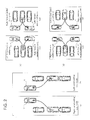
- FIG. 2 illustrates the pulling out modes corresponding to each of parking modes shown in FIG. 1 .
- Pulling out mode is preliminarily determined responsive to how the parking is done.
- FIG. 2 (a) illustrates a pulling out mode when the vehicle is parked in the left serial parking mode shown in FIG. 1(a) .
- the vehicle in this parking mode, the vehicle can be pulled out by moving forward to the right side. Therefore, the pulling out mode corresponding to the left serial parking mode is right serial pulling out mode.
- FIG. 2(b) illustrates a pulling out mode when the vehicle is parked in the right serial parking mode shown in FIG. 1(b) .
- this parking mode the vehicle can be pulled out by moving forward to the left side. Therefore, pulling out mode corresponding to right serial parking mode is left serial pulling out mode.
- FIG. 2(c1) illustrates a pulling out mode when the vehicle is parked according to the left backward parallel parking mode shown in FIG. 1(c1) .
- the vehicle in this parking mode, the vehicle can be pulled out by moving forward to the left or right. Therefore, the pulling out modes corresponding to the left backward parallel parking mode is two folds, left forward pulling out mode and right forward pulling out mode.
- FIG. 2(c2) illustrates a pulling out mode when the vehicle is placed according to the right backward parallel parking mode shown in FIG. 1(c2) .
- pulling out mode is two folds, left forward pulling out mode and right forward pulling out mode.
- FIG. 2(d1) illustrates a pulling out mode when the vehicle is parked according to the left forward parallel parking mode shown in (d1) of FIG. 1 .
- the pulling out mode corresponding to left forward parallel parking mode is two folds, left backward pulling out mode and right backward pulling out mode.
- FIG. 2(d2) illustrates a pulling out mode when the vehicle is parked according to the right forward parallel parking mode shown in FIG. 1(d2) .
- (d1) there are two pulling out modes, left backward pulling out mode and right backward pulling out mode.
- FIG. 1 and FIG. 2 are used.
- FIG. 3 illustrates a block diagram of the system installed in the vehicle to select and display the pulling out mode according to one embodiment of this invention.
- the system 10 for selection and display of the pulling out mode can be provided in electronic control unit (ECU) installed in the vehicle.
- ECU is computer comprising a central processing unit (CPU) and a memory.
- Wheel speed detector 12 which detects the wheel speed is connected to the system 10 for selection and display of the pulling out mode.
- wheel speed detector is formed by wheel speed sensors.
- the wheel speed sensors are installed in a pair of front wheels and a pair of rear wheels, respectively, and one pulse (hereinafter referred to as wheel speed pulse) is output in every predetermined rotation angle of these wheels. Rotation distances and rotation direction (forward or backward) of the wheels can be detected based on the wheel speed pulses.
- An automatic parking assistance system 14 may be connected to the system 10 for selection and display of the pulling out mode, but is not mandatory.
- An existing arbitrary system may be used for automatic parking assistance system 14.
- automatic parking assistance system 14 The performance of automatic parking assistance system 14 in this embodiment will be described simply with reference to FIG. 4 and FIG. 5 .
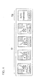
- a selection switches Sf of parking mode and a start switch Sg of automatic parking control are provided in the vehicle so that the driver can use them.
- the parking modes controlled by automatic parking assistance system 14 are left serial parking mode(a), right serial parking mode(b), left backward parallel parking mode(c1), and right backward parallel parking mode(d1) as illustrated in FIG. 1 .
- FIG. 5(a) illustrates a path table stored for the left backward parallel parking mode.
- the path table defines target steering angle ⁇ ref with respect to movement distance X of the vehicle.
- the path provides forward straight movement of distance a, right steering holding of distance b (holding the steering wheel turned to the right), forward straight movement of distance c, left steering holding of distance d (holding the steering wheel turned to the left), and forward straight movement of distance e.
- FIG. 5 (b) illustrates the path defined by the path table, and the positions A1-A3 corresponding to positions A1-A3 in the path table as illustrated in FIG. 5 (a) .
- a driver places a starting position mark M that is preliminarily provided in the vehicle to the end X1 of the entrance side Pe of parking space P by visual measurement as shown in FIG. 5 (b) , and moves the vehicle V so that the entrance side Pe of parking space P and the line in the direction of the width of the vehicle passing through the start position marks M of the vehicle are perpendicular to each other as illustrated shown as position A in FIG. 5(b) .
- the driver selects the left backward parking with the parking mode selection switch Sf as illustrated in FIG. 4 , the selected switch lights up. If the selected mode is not wrong, the driver releases his or her hands from the steering wheel of the vehicle and turns the starting switch Sg ON.
- EPS electric power steering
- the automatic parking assistance system 14 advises the driver to change sift positions from forward to backward.
- vehicle V is steered automatically and guided to the position A3 according to the target steering angle ⁇ ref based on moving distance X of the path table.
- An automatic parking assistance system 14 like this is described, for example, in Japanese Patent Application Publication No. 2003-175852 .
- an system 10 for selection and display of the pulling out mode comprises a wheel speed pulse measuring and holding unit 21, a parking path calculation unit 23, a parking mode determination unit 25, a parking mode memory 27, a pulling out operation detection unit 29, a pulling out mode memory 31, a pulling-out mode selection and display 33.
- the parking mode memory 27 and the pulling out mode memory 31 can be a conventional memory device.
- the parking mode determination unit 25 receives from the automatic parking assistance system 14 information about the parking mode performed by the system 14 and stores the information in the parking mode memory 27.
- the wheel speed pulse measuring and holding unit 21 counts the wheel speed pulses output from the wheel speed detective system 12, and holds the result in a memory.
- the parking path calculation unit 23 calculates the path the vehicle passed for parking (hereinafter referred to as parking path) based on the stored counting result of the wheel speed pulses.
- the parking mode determination unit 25 determines which parking mode is used to park the vehicle from plural parking modes based on the calculated parking path. The determined parking mode is stored in the parking mode memory 27.
- parking mode may not be calculated. In such conditions, "unable to determine” is stored in the parking mode memory 27.
- the pulling out operation starting unit 16 is provided in the vehicle for use by the driver.
- it can be provided in one embodiment in the form of a switch or a button.
- the driver operates the pulling out operation starting unit 16 by, for example, turning the switch ON, when he or she pulls out a car.
- pulling-out mode selection and display unit 33 selects a pulling out mode corresponding to the parking mode stored in the parking mode memory 27 with reference to pulling out mode memory 31.
- each of the parking modes is associated with corresponding pulling out mode, and the relation between them is preliminarily stored in the pulling out mode memory 31, for example, as a table shown in FIG. 6 . With reference to the table, the pulling out mode selection and display unit 33 selects pulling out mode corresponding to the determined parking mode.
- the left forward parallel pulling out mode and the right forward parallel pulling out mode are selected as the pulling out mode.
- two pulling out modes may be selected responsive to the left backward parallel parking mode because the vehicle may move to the left or to the right.
- all of pulling out modes are selected as shown the bottom blocks of FIG. 6 .
- Display pattern is defined according to each of the pulling out modes.
- Display pattern is data for displaying the pulling out mode, and stored in a memory.
- the left forward parallel pulling out mode and the right forward parallel pulling out mode correspond to display pattern C.
- Display pattern C is data that comprises characters, graphics and images that tell the driver that the vehicle is to be pulled out moving forward to the left or to the right.
- the pulling-out mode selection and display unit 33 identifies a display pattern corresponding to a selected pulling-out mode with reference to the table in FIG. 6 , and reads out the data of the identified display pattern, and displays the display pattern on a display unit 18.
- Display unit 18 is provided in the vehicle in the driver's view.
- a display unit of a navigation system may be used for this purpose.
- the display unit may be provided in an instrument panel.
- the pulling out mode may be informed to the driver aurally via speaker in addition to display.
- pulling out may be assisted by automatic steering in the same manner as parking is assisted by automatic steering.
- path is stored preliminarily according to each of pulling out modes as with path table for automatic parking as illustrated in FIG. 5(a) .
- a pulling out mode corresponding to the determined parking mode is displayed, and when one of the displayed pulling out modes is selected, the vehicle can be moved by automatic steering according to the path defined in the path table of the selected pulling out mode.
- a user may select a wrong switch by mistake.
- pulling out modes as shown in FIG. 6 are provided for selection by the selection switch, the right serial pulling out mode should be selected when the vehicle is parked according to the left serial parking mode.
- the user may push a wrong selection switch by mistake.
- selection of pulling out mode is displayed on the basis of the path the vehicle took for parking. Thus, this sort of mistake will be avoided.
- FIG. 7 shows a flow chart of the automatic parking assistance process wherein a parking mode performed by an automatic parking assistance system 14 is determined and stored. The process is performed by parking mode determination unit 25 in FIG.3 when parking is performed with automatic parking assistance system 14
- step S101 the variable p_mode representing a parking mode, is initialized to 0.
- step S102 parking operation is performed by automatic steering with automatic parking assistance system 14.
- step S103 determination is made as to whether parking operation is completed by automatic steering described above. If it is not completed (S103 is No), parking operation in step 102 continues. If it is completed (S103 is Yes), the process moves forward to step S104 to determine the parking mode. This is done by receiving information on the achieved parking mode from automatic parking assistance system 14.
- step S104 when determined parking mode is left serial parking mode, the value of parking mode variable p mode is set to 1 (S105), when determined parking mode is right serial parking mode, the value of parking mode variable p mode is set to 2 (S106).
- parking modes achieved by automatic parking assistance system 14 are the left backward parallel parking mode, the right backward parallel parking mode, the left serial parking mode, and the right serial parking mode.
- the left backward parallel parking mode and the right backward parallel parking mode lead to either one of the same pulling out modes respectively (the left forward parallel pulling out mode and the right forward parallel pulling out mode).
- the parking mode variable p_mode is set to the same value 3 (S107).
- the value of the parking mode variable p_mode is stored in a memory that maintains the memory even when ignition is placed in the off position.
- FIG. 8-11 illustrates the process of determining the parking mode when the driver parks the vehicle by manual handling of the steering wheel without using the automatic steering by automatic parking assistance system 14.
- the process comprises wheel speed pulse measuring and holding process, a process after IGOFF, parking path calculation process, and parking mode determination process. These processes are performed by wheel speed pulse measuring and holding unit 21, parking path calculation unit 23, and parking mode determination unit 25 shown in FIG. 3 .
- FIG. 8 illustrates a flow chart of wheel speed pulse measuring and holding process. This process is repeated at a specified time interval.
- step S201 it is determined whether vehicle speed as detected by a vehicle speed sensor (not shown) is slower than predetermined value (for example, 10 kilometers per hour). This is to done to determine whether parking operation is being performed or not. While parking operation is performed, vehicle speed is slow so that whether parking operation is being performed may be determined by checking the vehicle speed.
- predetermined value for example, 10 kilometers per hour
- step S201 If the vehicle speed is larger than a predetermined value (S201 is No), it indicates that parking operation is not being performed, and a variable n that represents count value of cycles of a predetermined time length (100 millisecond in this embodiment as described below in S212) is reset to zero in step S202. And in step S203, PR pulse buffer ⁇ R_ pulse [n] and RL pulse buffer ⁇ L_pulse [n] are cleared to zero. These pulse buffers have a data structure of an array of n elements.
- Each of the elements of the PR pulse buffer ⁇ R_ pulse [ ] holds the number of the pulses (pulses from a speed sensor of right rear wheel viewing front portions of the vehicle, called PR pulses) output from a wheel speed sensor of the right rear wheel during a corresponding cycle period.
- Each element of RL pulse buffer ⁇ L_pulse [ ] holds the number of the pulse (pulses from a sensor of left rear wheel viewing front portions of the vehicle, called PL pulses) output from a wheel speed sensor of the left rear wheel during a corresponding cycle period.
- step S204 whether PR pulse is output from the wheel speed sensor of right rear wheel is determined. If it is not output (S204 is No), the process proceed to step S208. If it is output (S204 is Yes), whether the PR pulse shows forward movement or backward movement is determined in step S205. If it shows forward movement (S205 is Yes), in step S206, PR pulse buffer ⁇ R_pulse [n] is incremented by 1. If it shows backward movement (S205 is No), in step S207, PR pulse buffer ⁇ R_pulse [n] is decremented by 1. The number of PR pulses that are required for the right rear wheel to move forward and backward is held by these processes.
- step S208 determines whether RL pulse is output from the wheel speed sensor in the left rear wheel. If it is not output (S208 is No), the process proceeds to step S212. If it is not output (S208 is Yes), it is determined in step S209 whether the RL pulse shows forward movement or backward movement. If it shows forward movement (S209 is Yes), in step S210, RL pulse buffer AL_pulse [n] is incremented by 1, and if it shows backward movement (S209 is No), in step S211, RL pulse buffer ⁇ L_pulse [n] is decremented by 1. The number of RL pulse which are required for the left rear wheel to move forward or backward is held by these processes.
- step S212 it is determined whether a predetermined time has passed from the end of previous cycle.
- the predetermined time is the time length of one cycle, and is 100 milliseconds in this embodiment. If the predetermined time has not passed (S212 is No), the process exits the flow. If the predetermined time has passed (5212 is Yes), the process exits the flow after the variable n is incremented by 1 in step 5213.
- the number of PR pulse and RL pulse are stored and held in a buffer or a memory.
- FIG. 9 illustrates a flow chart of the process following IGOFF, the process performed when ignition of a vehicle is turned off.
- step S301 Whether the value of the parking mode variable p_mode is zero or not is determined in step S301.
- the parking mode variable p_mode is a value from 1 to 3 when the automatic parking is performed by automatic parking assistance system 14. Therefore, when parking mode variable p_mode is not zero (S301 is No), it means that the automatic parking is performed by automatic parking assistance system 14. The process exits the flow.
- the parking mode variable remains zero (S301 is Yes)
- FIG. 13 (a) illustrates coordinate system used for calculating the parking path, and in this embodiment, the midpoint on the axle of a pair of the rear wheels is used as a reference point of the vehicle (alternatively, the center of gravity of the vehicle may be used as the reference point).
- Vehicle V has completed parking, and the position of the reference point is the origin O of the coordinates.
- X-axis extends from backward of the vehicle to forward on the axle of the vehicle V.
- Y-axis extends from right to left facing toward the front of the vehicle to traverse the vehicle width-wise.
- X-axis and y-axis are orthogonal to each other.
- FIG. 13(b) illustrates an example of the situation where vehicle V is yet to complete parking.
- the position of the vehicle in this situation is expressed as (x1, y1) in the x, y coordinate system of FIG. 13(a) .
- Line VA indicating the axle of vehicle V is at an angle ⁇ with respect to x-axis.
- the angle ⁇ is zero.
- the parking mode can be determine by the use of x, y, and ⁇ as described below.
- FIG. 14 illustrates a manner to distinguish between the backward serial parking and the backward parallel parking based on angle ⁇ .
- FIG. 14(a2) illustrates the behavior of vehicle V according to the left serial parking mode. Vehicle V moves forward from a starting position P1 to a position P2, and moves backward to a position P4 via a position P3.
- Angle ⁇ is the angle of a line VA along the axle of the vehicle to the x-axis. In the drawing, line VA and angle ⁇ are illustrated when vehicle V is at the position P3.
- FIG. 14(b2) illustrates the behavior of vehicle V according to the left backward parallel parking mode. Vehicle V moves forward from P1 to P2, and moves backward to P4 through position P3. When vehicle V is at the starting position P1, vehicle V is nearly perpendicular to the parking position P4 so that angle ⁇ is nearly 90 degrees. As the vehicle moves toward the parking position P4 from the starting position P1, magnitude (absolute value) of angle 8 decreases. When vehicle V reaches the parking position P4, angle ⁇ is zero. For the right backward parallel parking,
- the parking modes may be distinguished from the behaviors of
- is calculated.
- the value increases first and then decreases, and for backward parallel parking, it decreases with no increase (if it increases, it is in very small as compared to the serial parking).
- is smaller for the serial parking as compared to the backward parallel parking.
- this character may be used for distinguishing between the serial parking and the backward parallel parking.
- FIG. 15(a2) illustrates the behavior of vehicle V according to the left serial parking mode. Vehicle V moves forward from starting position P1 to a position P2, and moves backward to parking position P4 via position P3.
- the y-coordinate values of reference point (shown by a black dot) of vehicle V are negative values while the vehicle moves from position P1 to P4, and the magnitude generally decreases (short increase may take place).
- y-coordinate value becomes zero.
- FIG. 15(b2) illustrates the behavior of vehicle V according to the right serial parking mode. Vehicle V moves forward from the starting position P1 to a position P2, and moves backward to the parking position P4 via position P3.
- the y-coordinate values of the reference point (shown by black dot) of vehicle V are positive values while the vehicle moves through positions P1 to P4, and the magnitude generally (short increase may take place) decreases. When vehicle V reaches the parking position P4, the y-coordinate value becomes zero.
- these parking modes may be distinguished based on the behaviors of the y-coordinate values.
- the sum of y(t) is calculated.
- the sum is negative, and for the right serial parking, the sum is positive.
- the left serial parking and the right serial parking can be distinguished by the use of this feature.
- FIG. 16(a2) illustrates the behavior of vehicle V according to the left backward parallel parking mode.
- Vehicle V moves forward from the starting position P1 to a position P2, and moves backward to the parking position P4 via position P3.
- the x-coordinate values of the reference point (shown by black dot) of vehicle V are positive while the vehicle moves from positions P1 to P4, and the magnitude generally decreases (small increase may take place).
- the x-coordinate value becomes zero.
- the x-coordinate value assumes a similar profile.
- FIG. 16(b2) illustrates the behavior of vehicle V according to left forward parallel parking mode. Vehicle V moves forward from the starting position P1 to the parking position P3 via a position P2. The x-coordinate values of the reference point (black dot) of vehicle V are negative while the vehicle moves from the starting position P1 to the parking position P3. The magnitude generally decreases (small increase may take place). When vehicle V reaches the parking position P4, the x-coordinate value becomes zero. For the right forward parallel parking, x-coordinate value assumes a similar profile.
- the parking modes may be distinguished by the behavior of the x-coordinate values.
- the sum of x(t) is calculated.
- the sum is positive, and for the forward parallel parking, the sum is negative.
- the backward parallel parking and the forward parallel parking can be distinguished by use of this feature.
- the starting position P1 shown in FIG. 14-16 was described as the starting position for parking.
- the starting position P1 is the position where the vehicle speed falls below a predetermined value (for example, 10 kilometers per hour) as shown in step S201 of FIG. 8 .
- parking movement includes the behaviors of (a2) and (b2) shown in these drawings regardless of where the vehicle speed becomes as low as mentioned above.
- the profiles such as shown in (a1) and (b1) are obtained. Therefore, regardless of where the vehicle speed becomes low, when parking movement is performed, the parking mode may be determined on a basis of the profile of ⁇ , x and y as described above.
- the parking mode may be determined by obtaining angle ⁇ , x-coordinate value, and y-coordinate value.
- the angle ⁇ , x-coordinate value and y-coordinate value may be calculated on the basis of the number of PR pulses and the number of RL pulses of ⁇ R_pulse and ⁇ L_pulse stored in the buffer as described with reference to FIG. 8 .
- the calculation formula is shown in formula (4)-(6) below.
- Tred is a tread size of the rear wheel (length (m) between the right rear wheel and the left rear wheel).
- Pulse indicates moving distance (m) per pulse output from the wheel speed sensor, and can be calculated by multiplying rotation angle per pulse by the radius r of the tire.
- Tred and Pulse are preliminarily determined.
- the angle ⁇ , x-coordinate value, and y-coordinate value are zero when time t is zero.
- FIG. 17 illustrates circular movement of vehicle V when vehicle V parks in backward movement.
- the origin O is the position where parking is completed as described above. Or indicates the middle of a turning circle of the vehicle, code 111 indicates the turning path of the right rear wheel, code 113 indicates the turning path of the left rear wheel, and code 115 indicates the turning path of the reference point of vehicle V
- the reference point position of vehicle V is shown by M(t) and M(t+1).
- M(t+1) is located one cycle closer than M(t) to the parking completion position.
- VA(t) indicates the axle direction in position M(t), and this is a tangent line with respect to the turning circle 115 in position M(t).
- VA(t+1) indicates the axle direction in position M(t+1), and this is a tangent line with respect to turning circle 115 in position M(t+1).
- Angle ⁇ (t) in position M(t) and angle ⁇ (t+1) in position M(t+1) are shown.
- angle ⁇ (t) is a sum of angle ⁇ (t+1) and ⁇ .
- ⁇ is equal to the angle between the line connecting point Or and position M(t) and the line connecting point Or and position M(t+1).
- the radius of turning circle is indicated by r.
- r• ⁇ ⁇ L_pulse(n+t) ⁇ Pulse (this is moving distance of the left rear wheel between position M(t) and position M(t+1))
- (r+Tred) ⁇ ⁇ R_pulse(n+t) ⁇ Pulse (this is moving distance of the right rear wheel between position M(t) and position M(t+1)).
- ⁇ is calculated by eliminating r based on these two formulas.
- the presented formula (4) can be derived from the above.
- difference ⁇ y between y(t+1), y-coordinate value in position M(t+1), and y(t), y-coordinate value in position M(t) can be approximated by ⁇ sin of the linear distance between position M(t) and M(t+1).
- the linear distance between position M(t) and M(t+1) can be approximated by 0.5( ⁇ R_pulse(n+t)+ ⁇ L_pulse(n+t)) • Pulse.
- time length of a cycle for counting PR pulses and RL pulses is set so that approximation error is smaller than a predetermined value.
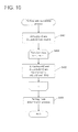
- step S401 ⁇ R_pulse[n] of the PR pulses buffer and ⁇ L_pulse[n] of the RL pulses buffer pulse[n] and RL pulse that are stored in FIG.8 are read in.
- step S402 according to the described formulas (4)-(6), loop which transforms the pulse read in into an angle ⁇ , a x-coordinate value, and a y-coordinate value is performed.
- the time t is shown by the length of a cycle (100 milliseconds in this embodiment), accordingly, ⁇ , x, and y are calculated in every cycle.
- FIG. 11 shows a flow chart of the parking mode determination process performed in step S404 of FIG. 10 .
- step S501 the profile of the absolute value of the calculated angle ⁇ (t) is examined.
- step 502 the profile of the calculated y(t) is examined.
- step S506 the profile of the calculated x(t) is examined.
- the parking mode is determined.
- the parking mode variable p_mode indicating the determined parking mode is stored in the memory as described with reference to FIG. 3 .
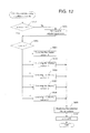
- FIG. 12 is a flow chart of a selection and display process that is performed according to the detection of the operation of the pulling out operation starting unit 16 in FIG. 3 by a user. This process is performed by the pulling-out mode selection and display 33.
- step S601 The parking mode variable p_mode in the memory is read out and determination is made whether it is zero or not. If it is zero (S601 is No), a parking path has not been calculated yet. That is, when a vehicle is parked by the automatic parking assistance system 14 as shown in FIG. 7 , the parking mode determination is performed. And when the vehicle is parked with manual steering as shown in FIG. 9 and an ignition is placed in the off position after being parked with manual steering, the parking mode determination is performed, too. However, when the vehicle is not parked by the automatic parking assistance system 14 and an ignition is not placed in the off position, the parking path has not been calculated. Accordingly, in such a case, the parking mode determination process ( FIG. 10 ) is performed in step S602. In this calculation process, the parking mode is determined ( FIG.11 ), and the value is set in the parking mode variable p_mode.
- a corresponding display pattern is selected according to the value of the parking mode variable p_mode.
- a display pattern can be selected by referring to a preliminarily stored table based on the parking mode shown by the parking mode variable p_mode.
- the parking mode variable p_mode when the value of the parking mode variable p_mode is 1, the left serial parking mode is represented, and a display pattern A is selected because the right serial pulling out mode corresponds thereto.
- the parking mode variable p_mode When the value of the parking mode variable p_mode is 2, the right serial parking mode is represented, and a display pattern B is selected because the left serial pulling out mode corresponds thereto.
- the parallel backward parking mode is represented, and a display pattern C is selected because the parallel forward pulling out mode corresponds thereto.
- the parallel forward parking mode is represented, and a display pattern D is selected because the parallel backward pulling out mode corresponds thereto.
- a display pattern E is selected because it represents "unable to determine”.
- the parking modes, the pulling out modes, and the display patterns are defined. But, a display pattern may be defined according to a parking mode because a pulling out mode is determined primarily according to a parking mode.
- the parking modes may be represented by the parking mode variables.
- the display pattern may be defined corresponding to the parking mode variables.
- step S609 data of the selected display pattern is read out from the memory and this is displayed on the display unit 18.
- the pulling out mode that is appropriate to the current parking condition is shown to a driver.
- the parking mode variable p_mode is reset to zero.
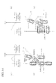
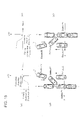
- a display pattern A illustrates the right serial pulling out mode.
- a look-forward view from the own vehicle V is displayed, and on the right of it, a graphic data 201 illustrates a manner that the vehicle V moves right forward to pull out. Since this display pattern A is a serial parking, a look-forward view from the own vehicle V is displayed as the condition where a vehicle U parked ahead of the own vehicle V is viewed from behind. With a display like this, a driver can be informed intuitively that there is a pulling out manner moving forward to the right.
- image data actually captured and some sort of graphic data may be used for the look-forward view from the vehicle V.
- the image data may be those caputered in real time by a imaging device installed in the vehicle. This is the same in the display patterns described below.
- a display pattern B shows the left serial pulling out mode. Similar to the display pattern A, a look-forward view from the own vehicle V where another vehicle U is parked in front of the own vehicle V is displayed. And, on the left of it, graphic data 203 illustrates a condition where the own vehicle V moves left forward to pull out. Thus, a driver can be informed intuitively of the pulling out mode moving forward to the left.
- a display pattern C shows the left and the right parallel forward pulling out mode.
- a look-forward view from the own vehicle V where another vehicle U and the like is parked side-by-side with the own vehicle V is displayed.
- Graphic data 205 illustrates a condition where the own vehicle V moves left forward to pull out
- graphic data 207 illustrates a condition where the own vehicle V moves right forward to pull out.
- a display pattern D shows the left and the right parallel backward pulling out mode. Similar to the display pattern C, a look-forward view from the own vehicle V where another vehicle U and the like is parked side-by-side with the own vehicle V is displayed. Graphic data 209 showing a condition where the own vehicle V moves left backward to pull out and graphic data 211 showing a condition where the own vehicle V moves right backward to pull out are displayed. With a display like this, a driver can be informed intuitively that there are pulling out manners of moving backward to the left or to the right.
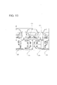
- a display pattern E in FIG. 19 appears when the parking mode is determined to be unable to determine, and all the parking modes are displayed.
- the pulling out mode cannot be determined because the parking mode could not be determined.
- the display includes graphic data 221 showing the left serial pulling out mode, graphic data 223 showing the left parallel forward pulling out mode, graphic data 225 showing the left parallel backward pulling out mode, graphic data 227 showing the right parallel forward pulling out mode, graphic data 229 showing the right parallel backward pulling out mode, and graphic data 231 showing the right serial pulling out mode. This display encourages the driver to determine a pulling out mode by himself or herself.
- a driver can recognize visually and immediately about the pulling out modes to select for pulling a vehicle out of a parking space where the vehicle is parked.
- the automatic steering may be used for pulling out.
- display screens shown in FIG.18 and 19 may be used for selection display screens.
- the display unit 18 may comprise a touch panel, and according to the determined pulling out mode, a selected display pattern may be displayed as shown in FIG. 18 and FIG. 19 .
- the driver may select a pulling out mode by selecting graphic data showing a desired pulling out mode. For example, in the display pattern C, if graphic data 205 is selected, the left parallel forward pulling out mode is selected.
- a path table preliminarily defined and stored for the pulling out modes is read out, a target steering angle for a moving distance of the vehicle is acquired, and the vehicle can be controlled such that the actual steering angle conforms to the target steering angle.
- the driver since there is one selectable pulling out mode for the display pattern A or B, the driver selects the displayed pulling out mode. On the other hand, there are multiple pulling out modes for the other display patterns, the driver may select a desired pulling out mode from the plurality of pulling out modes.
Landscapes
- Engineering & Computer Science (AREA)
- Chemical & Material Sciences (AREA)
- Combustion & Propulsion (AREA)
- Transportation (AREA)
- Mechanical Engineering (AREA)
- Traffic Control Systems (AREA)
- Steering Control In Accordance With Driving Conditions (AREA)
- Instrument Panels (AREA)
- Control Of Driving Devices And Active Controlling Of Vehicle (AREA)
Abstract
Description
- The present invention relates to a system that selects pulling out mode and displays it when a vehicle is pulling out of a parking space.
- In the prior art, parking assistance system by means of automatic steering was proposed. According to such a system, a vehicle can be parked at the desired parking space. With such parking assistance system, a user can choose modes of parking by the use of a switch, for example, between a backward parallel parking and a serial parking. Automatic steering of the vehicle is performed according to the parking mode selected by the switch. In regard to this point,
patent literature 1 described below shows an arrangement of the switch which user can manipulate without relying on characters and pictures. -
Patent literature 1
Japanese Patent Application Publication No.2003-175852 - There are some modes (patterns) for pulling out. If a driver selects a wrong pulling out mode, a vehicle cannot be pulled out or may clash to some sort of obstacle. It may be possible that a surveillance camera monitoring entire surroundings is used to avoid collision with obstacles. However, such a camera increases the cost.
- In contrast, the load of a driver can be reduced by the use of the automatic steering parking assistance system described above. When a vehicle is pulled out of the parking area, for example, in pulling out at narrow road and such, the driver will become overloaded, and may not be able to pull out in one trial. Therefore, a driver may need assistance by automatic steering for pulling out as well as for parking.
- When pulling out is assisted by automatic steering, if selection of pulling out mode is left to a driver as in parking mode, selected pulling out mode can be inappropriate according to the current parking situation. If inappropriate mode is selected, a vehicle may not be pulled out even with the automatic steering assistance.
- Accordingly, it is an object of the present invention to inform a driver of an appropriate pulling out mode that assists the driver to pull out a vehicle out of a parking area.
- According to one aspect of the invention, a system for selection and display of pulling out mode is provided in a vehicle. The system comprises a memory for storing pulling out modes indicating manners of pulling a vehicle out of a parking space, each mode corresponding to parking mode of the vehicle in the parking space. The system also includes a unit that determines parking mode of the vehicle when the vehicle is placed in the parking space, a detector for detecting an instruction from the driver of the vehicle for pulling out the vehicle from the parking space, and selection and display unit that selects a pulling out mode corresponding to the determined parking mode from the memory and displays the selected pulling out mode.
- According to the present invention, parking mode of a vehicle is determined when the vehicle is parked, and the pulling out mode that corresponds to the parking mode is selected and displayed so that the driver readily recognizes how to pull the vehicle out of the parking space. And, even when pulling out is assisted by automatic steering, only mode that facilitates pulling out is displayed to prevent the driver from selecting a wrong pulling out mode. Thus, an appropriate pulling out mode is selected, and pulling out can be done securely.
- According to one embodiment of the invention, the system includes a detector that detects the driving condition of the vehicle when the vehicle is parked at a parking space, and a path calculator that calculates paths of the vehicle corresponding to the detected driving condition when the vehicle is parked at the parking space. The unit that determines the parking mode based on the calculated path. Thus, even when the vehicle is parked with manual steering, parking mode is determined.
- According to one embodiment of the invention, parking assistance system is installed in the vehicle so that the parking is assisted by automatic steering when the vehicle is parked in a parking space. If parking assistance is performed by the parking assistance system when the vehicle is parked in a parking space, the parking mode determining unit acquires the parking mode from the parking assistance system. Thus, even when a vehicle is parked with automatic steering, parking mode of the parking can be determined.
- Thus, regardless of whether a vehicle is parked with automatic steering or with manual steering, the mode of parking can be determined so that pulling out mode corresponding to the parking mode can be selected and displayed.
- Other features and advantages of the present invention will be apparent from the detailed description which follows.
-
-
FIG. 1 illustrates parking mode according to one embodiment of this invention. -
FIG. 2 illustrates pulling out mode according to one embodiment of this invention. -
FIG. 3 illustrates general composition of system selecting and displaying pulling out mode according to one embodiment of this invention. -
FIG. 4 shows a switch provided by automatic parking assistance system according to one embodiment of this invention. -
FIG. 5 illustrates content of a path table and path of vehicle, used by automatic parking assistance system, according to one embodiment of this invention. -
FIG. 6 shows table of pulling out mode according to one embodiment of this invention. -
FIG. 7 shows a flow chart of automatic parking assistance process according to one embodiment of this invention. -
FIG. 8 shows a flow chart of wheel speed pulse measuring and holding process according to one embodiment of this invention. -
FIG. 9 shows a flow chart of the process following IGOFF according to one embodiment of this invention. -
FIG. 10 shows a flow chart of parking path calculation process according to one embodiment of this invention. -
FIG. 11 shows a flow chart of parking mode determination process according to one embodiment of this invention. -
FIG. 12 shows a flow chart of selection and display process of pulling out mode according to one embodiment of this invention. -
FIG. 13 show a coordinate system used for parking path calculation according to one embodiment of this invention. -
FIG. 14 illustrates a method of distinguishing between the serial parking and double parking with angle θ according to one embodiment of this invention. -
FIG. 15 illustrates a method of distinguishing between left serial parking and right serial parking with value of y according to one embodiment of this invention. -
FIG. 16 illustrates a method of distinguishing between backward serial parking and forward parking with a value of x according to one embodiment of this invention. -
FIG. 17 illustrates a method of converting wheel speed pulse θ into value of x and y according to one embodiment of this invention. -
FIG. 18 show display examples of display pattern, depending on pulling out mode, according to one embodiment of this invention. -
FIG. 19 shows display example of display pattern, depending on pulling out mode, according to one embodiment of this invention. - Now, embodiments of the present invention will be described with reference to the drawings.
- First, mode of parking a vehicle at a parking space, and mode of pulling out a vehicle from the parking space will be described.
-
FIG. 1 illustrates several parking modes. As illustrated in (a) and (b), parking modes includes a serial parking mode in which vehicle V is pulled in backwardly to park in the parking space in line with the other vehicles as shown in (a) and (b). The parking modes include a parallel backward parking mode in which vehicle V is moved backwardly to park in the parking space arranged in parallel with other vehicles as shown in (c). The parking modes includes a parallel forward parking mode in which the vehicle V is moved forwardly to park in the parking space arranged in parallel with the other vehicles as shown in (d). - In addition, serial parking modes are subdivided into left line parking mode in which vehicle V is placed in the parking space on the left side of the driver of vehicle V as shown in (a), and right line parking mode in which vehicle V is placed in the parking space on the right side of the driver of vehicle V as shown in (b).
- Similarly, the parallel backward parking mode is subdivided into left backward parking mode in which vehicle V is placed in the parking space on the left side of the driver of the vehicle V as shown in (c1), and right backward parking mode in which the vehicle V is placed in the parking space on the right side of the driver of the vehicle V as shown in (c2). Similarly, the parallel forward parking mode is subdivided into left forward parking mode in which the vehicle V is placed in the parking space on the left side of the driver of the vehicle V as shown in (d1), and right forward parking mode in which the vehicle V is placed in the parking space on the right side of the from driver of the vehicle V as shown in (d2).
-
FIG. 2 illustrates the pulling out modes corresponding to each of parking modes shown inFIG. 1 . Pulling out mode is preliminarily determined responsive to how the parking is done. -
FIG. 2 (a) illustrates a pulling out mode when the vehicle is parked in the left serial parking mode shown inFIG. 1(a) . As is clear from the drawings, in this parking mode, the vehicle can be pulled out by moving forward to the right side. Therefore, the pulling out mode corresponding to the left serial parking mode is right serial pulling out mode. -
FIG. 2(b) illustrates a pulling out mode when the vehicle is parked in the right serial parking mode shown inFIG. 1(b) . As is clear from the drawing, in this parking mode, the vehicle can be pulled out by moving forward to the left side. Therefore, pulling out mode corresponding to right serial parking mode is left serial pulling out mode. -
FIG. 2(c1) illustrates a pulling out mode when the vehicle is parked according to the left backward parallel parking mode shown inFIG. 1(c1) . As is clear from the drawings, in this parking mode, the vehicle can be pulled out by moving forward to the left or right. Therefore, the pulling out modes corresponding to the left backward parallel parking mode is two folds, left forward pulling out mode and right forward pulling out mode.FIG. 2(c2) illustrates a pulling out mode when the vehicle is placed according to the right backward parallel parking mode shown inFIG. 1(c2) . As is the case with (c1); pulling out mode is two folds, left forward pulling out mode and right forward pulling out mode. -
FIG. 2(d1) illustrates a pulling out mode when the vehicle is parked according to the left forward parallel parking mode shown in (d1) ofFIG. 1 . As is clear from the drawing, in this parking mode, the vehicle can be pulled out by moving backward to the left or right. Therefore, the pulling out mode corresponding to left forward parallel parking mode is two folds, left backward pulling out mode and right backward pulling out mode.FIG. 2(d2) illustrates a pulling out mode when the vehicle is parked according to the right forward parallel parking mode shown inFIG. 1(d2) . As is the case with (d1), there are two pulling out modes, left backward pulling out mode and right backward pulling out mode. - In the following discussion, the parking mode and pulling out mode illustrated in
FIG. 1 andFIG. 2 are used. -
FIG. 3 illustrates a block diagram of the system installed in the vehicle to select and display the pulling out mode according to one embodiment of this invention. - The
system 10 for selection and display of the pulling out mode can be provided in electronic control unit (ECU) installed in the vehicle. ECU is computer comprising a central processing unit (CPU) and a memory.Wheel speed detector 12 which detects the wheel speed is connected to thesystem 10 for selection and display of the pulling out mode. In one embodiment, wheel speed detector is formed by wheel speed sensors. The wheel speed sensors are installed in a pair of front wheels and a pair of rear wheels, respectively, and one pulse (hereinafter referred to as wheel speed pulse) is output in every predetermined rotation angle of these wheels. Rotation distances and rotation direction (forward or backward) of the wheels can be detected based on the wheel speed pulses. - An automatic
parking assistance system 14 may be connected to thesystem 10 for selection and display of the pulling out mode, but is not mandatory. An existing arbitrary system may be used for automaticparking assistance system 14. - The performance of automatic
parking assistance system 14 in this embodiment will be described simply with reference toFIG. 4 andFIG. 5 . As shown inFIG. 4 , a selection switches Sf of parking mode and a start switch Sg of automatic parking control are provided in the vehicle so that the driver can use them. As is clear from the sketches of selection switches Sf, in this example, the parking modes controlled by automaticparking assistance system 14 are left serial parking mode(a), right serial parking mode(b), left backward parallel parking mode(c1), and right backward parallel parking mode(d1) as illustrated inFIG. 1 . - A path table is stored in a memory for each of the parking modes for automatic steering of the vehicle.
FIG. 5(a) illustrates a path table stored for the left backward parallel parking mode. The path table defines target steering angle θref with respect to movement distance X of the vehicle. For the left backward parallel parking mode, the path provides forward straight movement of distance a, right steering holding of distance b (holding the steering wheel turned to the right), forward straight movement of distance c, left steering holding of distance d (holding the steering wheel turned to the left), and forward straight movement of distance e.FIG. 5 (b) illustrates the path defined by the path table, and the positions A1-A3 corresponding to positions A1-A3 in the path table as illustrated inFIG. 5 (a) . - The performance of automatic parking control will be briefly described. A driver places a starting position mark M that is preliminarily provided in the vehicle to the end X1 of the entrance side Pe of parking space P by visual measurement as shown in
FIG. 5 (b) , and moves the vehicle V so that the entrance side Pe of parking space P and the line in the direction of the width of the vehicle passing through the start position marks M of the vehicle are perpendicular to each other as illustrated shown as position A inFIG. 5(b) . When the driver selects the left backward parking with the parking mode selection switch Sf as illustrated inFIG. 4 , the selected switch lights up. If the selected mode is not wrong, the driver releases his or her hands from the steering wheel of the vehicle and turns the starting switch Sg ON. The automaticparking assistance system 14 switches from an electric power steering (EPS) mode to the automatic steering control mode responsive to turning on of the starting switch Sg. If the automaticparking assistance system 14 switches to the automatic steering control mode, it detects rotation angle θ of the wheel based on the accumulated number of output pulses from the wheel speed sensor, and calculates moving distance of the vehicle in accordance with X=rθ, r being the radius of the tire of the wheel. The automaticparking assistance system 14 calculates the corresponding target steering angle θref with reference to the path table for left backward parallel parking as illustrated inFIG. 5(a) on a basis of moving distance X, and controls a steering actuator so that actual steering angle of the steering wheel of the vehicle V is equal to target steering angle θref, thereby rotating the front wheels automatically. Thus, when the vehicle arrives to position A2 from position A1, the automaticparking assistance system 14 advises the driver to change sift positions from forward to backward. When shift change is completed by the driver, in a similar way, vehicle V is steered automatically and guided to the position A3 according to the target steering angle θref based on moving distance X of the path table. An automaticparking assistance system 14 like this is described, for example, in Japanese Patent Application Publication No.2003-175852 - Referring to
FIG. 3 again, ansystem 10 for selection and display of the pulling out mode comprises a wheel speed pulse measuring and holdingunit 21, a parkingpath calculation unit 23, a parkingmode determination unit 25, aparking mode memory 27, a pulling outoperation detection unit 29, a pulling outmode memory 31, a pulling-out mode selection anddisplay 33. Theparking mode memory 27 and the pulling outmode memory 31 can be a conventional memory device. - To select a pulling out mode, it is necessary to determine what parking mode was used to park the vehicle. When parking was done automatically by automatic
parking assistance system 14, the parkingmode determination unit 25 receives from the automaticparking assistance system 14 information about the parking mode performed by thesystem 14 and stores the information in theparking mode memory 27. - When parking was done by the driver manually handling the steering wheel without using the automatic
parking assistance system 14, a process of determining parking mode needs to be performed. For this purpose, when parking is being done, the wheel speed pulse measuring and holdingunit 21 counts the wheel speed pulses output from the wheelspeed detective system 12, and holds the result in a memory. The parkingpath calculation unit 23 calculates the path the vehicle passed for parking (hereinafter referred to as parking path) based on the stored counting result of the wheel speed pulses. The parkingmode determination unit 25 determines which parking mode is used to park the vehicle from plural parking modes based on the calculated parking path. The determined parking mode is stored in theparking mode memory 27. - When the wheel speed pulses cannot be measured due to some sort of error or when parking path cannot be determined for reason, parking mode may not be calculated. In such conditions, "unable to determine" is stored in the
parking mode memory 27. - The pulling out
operation starting unit 16 is provided in the vehicle for use by the driver. For example, it can be provided in one embodiment in the form of a switch or a button. The driver operates the pulling outoperation starting unit 16 by, for example, turning the switch ON, when he or she pulls out a car. - When a user operates the pulling out
operation starting unit 16, it is detected by the pulling out startingoperation detection unit 29. Depending on the detection, pulling-out mode selection anddisplay unit 33 selects a pulling out mode corresponding to the parking mode stored in theparking mode memory 27 with reference to pulling outmode memory 31. As described with reference toFIG. 1 andFIG. 2 , each of the parking modes is associated with corresponding pulling out mode, and the relation between them is preliminarily stored in the pulling outmode memory 31, for example, as a table shown inFIG. 6 . With reference to the table, the pulling out mode selection anddisplay unit 33 selects pulling out mode corresponding to the determined parking mode. For example, if the determined parking mode is the left backward parallel parking mode, the left forward parallel pulling out mode and the right forward parallel pulling out mode are selected as the pulling out mode. As shown in (c1) ofFIG. 2 , two pulling out modes may be selected responsive to the left backward parallel parking mode because the vehicle may move to the left or to the right. And, if the parking mode was "unable to determine", all of pulling out modes are selected as shown the bottom blocks ofFIG. 6 . - In the table in
FIG. 6 , display pattern is defined according to each of the pulling out modes. Display pattern is data for displaying the pulling out mode, and stored in a memory. For example, the left forward parallel pulling out mode and the right forward parallel pulling out mode correspond to display pattern C. Display pattern C is data that comprises characters, graphics and images that tell the driver that the vehicle is to be pulled out moving forward to the left or to the right. The pulling-out mode selection anddisplay unit 33 identifies a display pattern corresponding to a selected pulling-out mode with reference to the table inFIG. 6 , and reads out the data of the identified display pattern, and displays the display pattern on adisplay unit 18. An embodiment of the display pattern will be discussed below.Display unit 18 is provided in the vehicle in the driver's view. For example, a display unit of a navigation system may be used for this purpose. The display unit may be provided in an instrument panel. The pulling out mode may be informed to the driver aurally via speaker in addition to display. - Thus, when a parked vehicle is pulled out, a proper pulling out mode will be displayed according to present parking situation so that the driver may recognize how to pull out the vehicle.
- Though not shown in the figure, pulling out may be assisted by automatic steering in the same manner as parking is assisted by automatic steering. In this case, path is stored preliminarily according to each of pulling out modes as with path table for automatic parking as illustrated in
FIG. 5(a) . As described above, a pulling out mode corresponding to the determined parking mode is displayed, and when one of the displayed pulling out modes is selected, the vehicle can be moved by automatic steering according to the path defined in the path table of the selected pulling out mode. - For automatic steering of pulling out like this, with a selection switch for selecting pulling out modes such as the parking modes Sf as shown in
FIG. 4 , a user may select a wrong switch by mistake. For example, if pulling out modes as shown inFIG. 6 are provided for selection by the selection switch, the right serial pulling out mode should be selected when the vehicle is parked according to the left serial parking mode. The user may push a wrong selection switch by mistake. When an inappropriate pulling out mode is selected, not only the pulling out operation is difficult but also it may lead to a clash with some sort of obstacle. According to the present invention, selection of pulling out mode is displayed on the basis of the path the vehicle took for parking. Thus, this sort of mistake will be avoided. - With reference to
FIGS. 7-12 , according to one embodiment of the invention, details of the process performed by the select anddisplay unit 10 as illustrated inFIG.3 will be described. -
FIG. 7 shows a flow chart of the automatic parking assistance process wherein a parking mode performed by an automaticparking assistance system 14 is determined and stored. The process is performed by parkingmode determination unit 25 inFIG.3 when parking is performed with automaticparking assistance system 14 - In step S101, the variable p_mode representing a parking mode, is initialized to 0. In step S102, as previously described, parking operation is performed by automatic steering with automatic
parking assistance system 14. - In step S103, determination is made as to whether parking operation is completed by automatic steering described above. If it is not completed (S103 is No), parking operation in step 102 continues. If it is completed (S103 is Yes), the process moves forward to step S104 to determine the parking mode. This is done by receiving information on the achieved parking mode from automatic
parking assistance system 14. - In step S104, when determined parking mode is left serial parking mode, the value of parking mode variable p mode is set to 1 (S105), when determined parking mode is right serial parking mode, the value of parking mode variable p mode is set to 2 (S106).
- In this embodiment, parking modes achieved by automatic
parking assistance system 14 are the left backward parallel parking mode, the right backward parallel parking mode, the left serial parking mode, and the right serial parking mode. As shown inFIG. 6 , the left backward parallel parking mode and the right backward parallel parking mode lead to either one of the same pulling out modes respectively (the left forward parallel pulling out mode and the right forward parallel pulling out mode). Thus, for the left backward parallel parking mode and the right backward parallel parking mode, the parking mode variable p_mode is set to the same value 3 (S107). - Thus, the value of the parking mode variable p_mode is stored in a memory that maintains the memory even when ignition is placed in the off position.
-
FIG. 8-11 illustrates the process of determining the parking mode when the driver parks the vehicle by manual handling of the steering wheel without using the automatic steering by automaticparking assistance system 14. The process comprises wheel speed pulse measuring and holding process, a process after IGOFF, parking path calculation process, and parking mode determination process. These processes are performed by wheel speed pulse measuring and holdingunit 21, parkingpath calculation unit 23, and parkingmode determination unit 25 shown inFIG. 3 . -
FIG. 8 illustrates a flow chart of wheel speed pulse measuring and holding process. This process is repeated at a specified time interval. - In step S201, it is determined whether vehicle speed as detected by a vehicle speed sensor (not shown) is slower than predetermined value (for example, 10 kilometers per hour). This is to done to determine whether parking operation is being performed or not. While parking operation is performed, vehicle speed is slow so that whether parking operation is being performed may be determined by checking the vehicle speed.
- If the vehicle speed is larger than a predetermined value (S201 is No), it indicates that parking operation is not being performed, and a variable n that represents count value of cycles of a predetermined time length (100 millisecond in this embodiment as described below in S212) is reset to zero in step S202. And in step S203, PR pulse buffer ΔR_ pulse [n] and RL pulse buffer ΔL_pulse [n] are cleared to zero. These pulse buffers have a data structure of an array of n elements. Each of the elements of the PR pulse buffer ΔR_ pulse [ ] holds the number of the pulses (pulses from a speed sensor of right rear wheel viewing front portions of the vehicle, called PR pulses) output from a wheel speed sensor of the right rear wheel during a corresponding cycle period. Each element of RL pulse buffer ΔL_pulse [ ] holds the number of the pulse (pulses from a sensor of left rear wheel viewing front portions of the vehicle, called PL pulses) output from a wheel speed sensor of the left rear wheel during a corresponding cycle period.
- If the vehicle speed is lower than a predetermined value (S201 is Yes), in step S204, whether PR pulse is output from the wheel speed sensor of right rear wheel is determined. If it is not output (S204 is No), the process proceed to step S208. If it is output (S204 is Yes), whether the PR pulse shows forward movement or backward movement is determined in step S205. If it shows forward movement (S205 is Yes), in step S206, PR pulse buffer ΔR_pulse [n] is incremented by 1. If it shows backward movement (S205 is No), in step S207, PR pulse buffer ΔR_pulse [n] is decremented by 1. The number of PR pulses that are required for the right rear wheel to move forward and backward is held by these processes.
- The process proceeds to step S208, where whether RL pulse is output from the wheel speed sensor in the left rear wheel. If it is not output (S208 is No), the process proceeds to step S212. If it is not output (S208 is Yes), it is determined in step S209 whether the RL pulse shows forward movement or backward movement. If it shows forward movement (S209 is Yes), in step S210, RL pulse buffer AL_pulse [n] is incremented by 1, and if it shows backward movement (S209 is No), in step S211, RL pulse buffer ΔL_pulse [n] is decremented by 1. The number of RL pulse which are required for the left rear wheel to move forward or backward is held by these processes.
- The process proceeds to step S212, and it is determined whether a predetermined time has passed from the end of previous cycle. As previously described, the predetermined time is the time length of one cycle, and is 100 milliseconds in this embodiment. If the predetermined time has not passed (S212 is No), the process exits the flow. If the predetermined time has passed (5212 is Yes), the process exits the flow after the variable n is incremented by 1 in step 5213.
- Thus, from zero to n, with respect to each cycle, the number of PR pulse and RL pulse are stored and held in a buffer or a memory.
-
FIG. 9 illustrates a flow chart of the process following IGOFF, the process performed when ignition of a vehicle is turned off. - Whether the value of the parking mode variable p_mode is zero or not is determined in step S301. As described with reference to
FIG. 7 , the parking mode variable p_mode is a value from 1 to 3 when the automatic parking is performed by automaticparking assistance system 14. Therefore, when parking mode variable p_mode is not zero (S301 is No), it means that the automatic parking is performed by automaticparking assistance system 14. The process exits the flow. When the parking mode variable remains zero (S301 is Yes), it means that the vehicle has been parked with manual steering so that the path of parking (FIG. 10 ) is calculated in step S302. - Before describing parking path calculating process, basic idea for calculating the parking path is described with reference to the drawings of
FIG. 13-17 .FIG. 13 (a) illustrates coordinate system used for calculating the parking path, and in this embodiment, the midpoint on the axle of a pair of the rear wheels is used as a reference point of the vehicle (alternatively, the center of gravity of the vehicle may be used as the reference point). Vehicle V has completed parking, and the position of the reference point is the origin O of the coordinates. X-axis extends from backward of the vehicle to forward on the axle of the vehicle V. Y-axis extends from right to left facing toward the front of the vehicle to traverse the vehicle width-wise. X-axis and y-axis are orthogonal to each other. -
FIG. 13(b) illustrates an example of the situation where vehicle V is yet to complete parking. The position of the vehicle in this situation is expressed as (x1, y1) in the x, y coordinate system ofFIG. 13(a) . Line VA indicating the axle of vehicle V is at an angle θ with respect to x-axis. When parking is done as the n inFIG. 13(a) , the angle θ is zero. - The parking mode can be determine by the use of x, y, and θ as described below.
-
FIG. 14 illustrates a manner to distinguish between the backward serial parking and the backward parallel parking based on angle θ.FIG. 14(a1) illustrates transition (profile) of the absolute value of θ with respect to time t when parking is performed with the left serial parking mode. t=0 when parking is completed.FIG. 14(a2) illustrates the behavior of vehicle V according to the left serial parking mode. Vehicle V moves forward from a starting position P1 to a position P2, and moves backward to a position P4 via a position P3. Angle θ is the angle of a line VA along the axle of the vehicle to the x-axis. In the drawing, line VA and angle θare illustrated when vehicle V is at the position P3. When vehicle V is at the starting position P1, vehicle V is positioned nearly in parallel with a parking position P4 so thatangle 8 is nearly zero. As the vehicle moves from the starting position P1 to the parking position P4, magnitude (absolute value) of angle θ increases and then decreases. When vehicle V arrives at the parking position P4, angle θ becomes zero as described above. For the right serial parking, |θ| assumes a similar profile. -
FIG. 14(b1) illustrates a transition (profile) of the absolute value of θ with respect to time t when parking is performed according to the left backward parallel parking mode. t=0 when parking is completed.FIG. 14(b2) illustrates the behavior of vehicle V according to the left backward parallel parking mode. Vehicle V moves forward from P1 to P2, and moves backward to P4 through position P3. When vehicle V is at the starting position P1, vehicle V is nearly perpendicular to the parking position P4 so that angle θ is nearly 90 degrees. As the vehicle moves toward the parking position P4 from the starting position P1, magnitude (absolute value) ofangle 8 decreases. When vehicle V reaches the parking position P4, angle θ is zero. For the right backward parallel parking, |θ| assumes a similar profile. For the left forward parallel parking and the right forward parallel parking, |θ| also assumes a similar profile. - As the behaviors of |θ| for the serial parking and the backward parallel parking are different, the parking modes may be distinguished from the behaviors of |θ|.
- In one embodiment, as shown in formula (1) below, the sum of differentiated |θ(t)| is calculated. For the serial parking, the value increases first and then decreases, and for backward parallel parking, it decreases with no increase (if it increases, it is in very small as compared to the serial parking). Thus, the sum of differentiated |θ(t)| is smaller for the serial parking as compared to the backward parallel parking. Thus, this character may be used for distinguishing between the serial parking and the backward parallel parking.

- Then, with reference to
FIG. 15 , for the serial parking mode, a method for distinguishing between the left serial parking mode and the right serial parking mode will be described. -
FIG. 15(a1) illustrates transition (profile) of the y-coordinate values of the reference point of vehicle V with respect to time t when parking is performed in the left serial parking mode, with t=0 when parking is completed.FIG. 15(a2) illustrates the behavior of vehicle V according to the left serial parking mode. Vehicle V moves forward from starting position P1 to a position P2, and moves backward to parking position P4 via position P3. The y-coordinate values of reference point (shown by a black dot) of vehicle V are negative values while the vehicle moves from position P1 to P4, and the magnitude generally decreases (short increase may take place). When vehicle V reaches the parking position P4, y-coordinate value becomes zero. - On the other hand,
FIG. 15(b1) illustrates transition (profile) of y-coordinate values of the reference point of vehicle V relative to time t when parking is performed according to the right serial parking mode, with t=0 when parking is completed.FIG. 15(b2) illustrates the behavior of vehicle V according to the right serial parking mode. Vehicle V moves forward from the starting position P1 to a position P2, and moves backward to the parking position P4 via position P3. The y-coordinate values of the reference point (shown by black dot) of vehicle V are positive values while the vehicle moves through positions P1 to P4, and the magnitude generally (short increase may take place) decreases. When vehicle V reaches the parking position P4, the y-coordinate value becomes zero. - Thus, as the behaviors of the y-coordinate values are different for the left serial parking and the right serial parking, these parking modes may be distinguished based on the behaviors of the y-coordinate values.
- In one embodiment, as shown in formula (2) below, the sum of y(t) is calculated. For the left serial parking, the sum is negative, and for the right serial parking, the sum is positive. The left serial parking and the right serial parking can be distinguished by the use of this feature.

- Then, with reference to
FIG. 16 , for the parallel parking mode, a manner of distinguishing between the backward parallel parking mode and the forward parallel parking mode will be described. -
FIG. 16(a1) illustrates transition (profile) of x-coordinate value of the reference point of vehicle V with respect to time t when parking is performed according to the left backward parallel parking mode with t=0 when parking is completed.FIG. 16(a2) illustrates the behavior of vehicle V according to the left backward parallel parking mode. Vehicle V moves forward from the starting position P1 to a position P2, and moves backward to the parking position P4 via position P3. The x-coordinate values of the reference point (shown by black dot) of vehicle V are positive while the vehicle moves from positions P1 to P4, and the magnitude generally decreases (small increase may take place). When vehicle V reaches the parking position P4, the x-coordinate value becomes zero. For the right backward parallel parking, the x-coordinate value assumes a similar profile. - On the other hand,
FIG. 16(b1) illustrates transition (profile) of the y-coordinate values of the reference point of vehicle V with respect to time t when parking is performed according to the forward parallel parking mode with t=0 when parking is completed.FIG. 16(b2) illustrates the behavior of vehicle V according to left forward parallel parking mode. Vehicle V moves forward from the starting position P1 to the parking position P3 via a position P2. The x-coordinate values of the reference point (black dot) of vehicle V are negative while the vehicle moves from the starting position P1 to the parking position P3. The magnitude generally decreases (small increase may take place). When vehicle V reaches the parking position P4, the x-coordinate value becomes zero. For the right forward parallel parking, x-coordinate value assumes a similar profile. - Thus, as the behavior of the x-coordinate values differ for the backward parallel parking and the forward parallel parking, the parking modes may be distinguished by the behavior of the x-coordinate values.
- In one embodiment, as shown in formula (3) below, the sum of x(t) is calculated. For the backward parallel parking, the sum is positive, and for the forward parallel parking, the sum is negative. The backward parallel parking and the forward parallel parking can be distinguished by use of this feature.

- The starting position P1 shown in
FIG. 14-16 was described as the starting position for parking. Actually, the starting position P1 is the position where the vehicle speed falls below a predetermined value (for example, 10 kilometers per hour) as shown in step S201 ofFIG. 8 . However, parking movement includes the behaviors of (a2) and (b2) shown in these drawings regardless of where the vehicle speed becomes as low as mentioned above. Thus, the profiles such as shown in (a1) and (b1) are obtained. Therefore, regardless of where the vehicle speed becomes low, when parking movement is performed, the parking mode may be determined on a basis of the profile of θ, x and y as described above. - Thus, it is found that the parking mode may be determined by obtaining angle θ, x-coordinate value, and y-coordinate value. The angle θ, x-coordinate value and y-coordinate value may be calculated on the basis of the number of PR pulses and the number of RL pulses of ΔR_pulse and ΔL_pulse stored in the buffer as described with reference to
FIG. 8 . The calculation formula is shown in formula (4)-(6) below. - Here, Tred is a tread size of the rear wheel (length (m) between the right rear wheel and the left rear wheel). Pulse indicates moving distance (m) per pulse output from the wheel speed sensor, and can be calculated by multiplying rotation angle per pulse by the radius r of the tire. Tred and Pulse are preliminarily determined. Time t=0 indicates completion of parking. The angle θ, x-coordinate value, and y-coordinate value are zero when time t is zero. As described with reference to
FIG. 8 , parking starting time t=-n. Therefore, from t=-1 to t=-n, that is, from the completion of parking to start of parking, θ, x and y are obtained for each value of t in the following formula. For each element in buffer of ΔR_pulse and ΔL_pulse, as described with reference toFIG. 8 , positive values are stored while the vehicle moves forward and negative values are stored while the vehicle moves backward. The minus code at the head of the right terms of formulas (4)-(6) is assigned for adjusting this matter.


- Basis for formulas presented above will be described with reference to
FIG. 17. (a) inFIG. 17 illustrates circular movement of vehicle V when vehicle V parks in backward movement. The origin O is the position where parking is completed as described above. Or indicates the middle of a turning circle of the vehicle,code 111 indicates the turning path of the right rear wheel,code 113 indicates the turning path of the left rear wheel, andcode 115 indicates the turning path of the reference point of vehicle V - The reference point position of vehicle V is shown by M(t) and M(t+1). M(t+1) is located one cycle closer than M(t) to the parking completion position. Here, t is shown in time length (100 millisecond in this embodiment) of a cycle as described above (therefore, the interval between t=-1 and t=-2 is 100 millisecond).
- VA(t) indicates the axle direction in position M(t), and this is a tangent line with respect to the
turning circle 115 in position M(t). VA(t+1) indicates the axle direction in position M(t+1), and this is a tangent line with respect to turningcircle 115 in position M(t+1). Angle θ(t) in position M(t) and angle θ(t+1) in position M(t+1) are shown. - As is clear from the drawings, angle θ(t) is a sum of angle θ(t+1) and Δθ. Δθ is equal to the angle between the line connecting point Or and position M(t) and the line connecting point Or and position M(t+1). The radius of turning circle is indicated by r. Then, r• Δθ=ΔL_pulse(n+t)·Pulse (this is moving distance of the left rear wheel between position M(t) and position M(t+1)), and (r+Tred)·Δθ=ΔR_pulse(n+t)·Pulse (this is moving distance of the right rear wheel between position M(t) and position M(t+1)). Δθ is calculated by eliminating r based on these two formulas. The presented formula (4) can be derived from the above.
- The distance between position M(t) and M(t+1) in (a) is shown large for the sake of easy comprehension. Actually, the distance is small as PR pulse and RL pulse are counted per cycle of short period such as 100 millisecond as described with reference to
FIG. 8 . Thus, as illustrated in (b), difference Δx between x(t+1), x-coordinate value in position M(t+1) , and x(t), x-coordinate value in position M(t), can be approximated by cosθ of the linear distance between position M(t) and M(t+1). Similarly for y-coordinate value, difference Δy between y(t+1), y-coordinate value in position M(t+1), and y(t), y-coordinate value in position M(t), can be approximated by θsin of the linear distance between position M(t) and M(t+1). The linear distance between position M(t) and M(t+1) can be approximated by 0.5(ΔR_pulse(n+t)+ΔL_pulse(n+t)) • Pulse. (In other words, time length of a cycle for counting PR pulses and RL pulses is set so that approximation error is smaller than a predetermined value.) The presented formula (5) and (6) can be derived from the above. - The basis of the formulas for converting the wheel speed obtained according to
FIG. 8 into angle θ, x-coordinate value and y-coordinate value has been described above. - Now, back to
FIG. 10 , the flow chart of the parking path calculation process performed in step S302 inFIG. 9 , the process will be described. - In step S401, ΔR_pulse[n] of the PR pulses buffer and ΔL_pulse[n] of the RL pulses buffer pulse[n] and RL pulse that are stored in
FIG.8 are read in. In S402, according to the described formulas (4)-(6), loop which transforms the pulse read in into an angle θ, a x-coordinate value, and a y-coordinate value is performed. In loop of S402, the initial value of the time t, the last value, and the incremental value are shown by -1;-n;-1 respectively. Accordingly, the loop is repeated decrementing by one from t=-1 to t=-n. Here, as described above, the time t is shown by the length of a cycle (100 milliseconds in this embodiment), accordingly, θ, x, and y are calculated in every cycle. When t=0, the initial value of the time t, θ, x, and y are set to the initial value zero respectively as described above. - When the process exits this loop, it moves forward to S404, and a parking mode determination process of determining the parking mode is performed.
-
FIG. 11 shows a flow chart of the parking mode determination process performed in step S404 ofFIG. 10 . - In step S501, the profile of the absolute value of the calculated angle θ(t) is examined. In particular, as shown in a formula (1), values acquired by differentiating the absolute value of the calculated angle θ(t) are summed from time t=-n to time t=0, and it is determined whether the summed total is equal to or less than a predetermined value or not. If the summed total is equal or lower than the predetermined value, the process is determined as the serial parking mode and moves forward to S502. If the summed total is eaqual to or less than the predetermined value, the mode is determined to be the parallel backward parking mode and moves forward to S506.
- In
step 502, the profile of the calculated y(t) is examined. In particular, as shown in a formula (2), the calculated values of y are summed from time t=-n to time t=0, and it is determined whether the summed total is a positive value or a negative value. If the summed total is a negative value, the mode is determined to be the left serial parking mode, and thevalue 1 is set in a parking mode variable p_mode (S503). If the summed total is a positive value, the mode is determined to be the right serial parking mode, and thevalue 2 is set in the parking mode variable p_mode (S504). - As described above, by some sort of error, when a wheel speed pulse cannot be acquired, a stored wheel speed pulse cannot be read in, or either θ or y cannot be calculated and such, the mode is determined to be unable to determine and the
value 5 is set in the parking mode variable p_mode (S505) because a parking mode cannot be determined. - On the other hand, in step S506, the profile of the calculated x(t) is examined. In particular, as shown in a formula (3), the calculated values of x are summed from time t=-n to time t=0, and, it is determined whether the summed total is a positive value or a negative value. If the summed total is a positive value, the mode is determined to be the parallel backward parking mode, and the
value 3 is set in the parking mode variable p_mode (S507). If the summed total is a negative value, the mode is determined to be the parallel forward parking mode, and thevalue 4 is set in the parking mode variable p_mode (S508). - By some sort of error, when a wheel speed pulse cannot be acquired, a stored wheel speed pulse cannot be read in, or either θ or x cannot be calculated, the mode is determined as unable to determine and the
value 5 is set in the parking mode variable p_mode (S509) because the parking mode cannot be determined. - Thus, when it is determined that a parking is done regardless of whether a vehicle was parked with an assistance of automatic steering or with a manual steering, the parking mode is determined. The parking mode variable p_mode indicating the determined parking mode is stored in the memory as described with reference to
FIG. 3 . -
FIG. 12 is a flow chart of a selection and display process that is performed according to the detection of the operation of the pulling outoperation starting unit 16 inFIG. 3 by a user. This process is performed by the pulling-out mode selection anddisplay 33. - In step S601, The parking mode variable p_mode in the memory is read out and determination is made whether it is zero or not. If it is zero (S601 is No), a parking path has not been calculated yet. That is, when a vehicle is parked by the automatic
parking assistance system 14 as shown inFIG. 7 , the parking mode determination is performed. And when the vehicle is parked with manual steering as shown inFIG. 9 and an ignition is placed in the off position after being parked with manual steering, the parking mode determination is performed, too. However, when the vehicle is not parked by the automaticparking assistance system 14 and an ignition is not placed in the off position, the parking path has not been calculated. Accordingly, in such a case, the parking mode determination process (FIG. 10 ) is performed in step S602. In this calculation process, the parking mode is determined (FIG.11 ), and the value is set in the parking mode variable p_mode. - When a value other than zero is set in the parking mode variable p_mode (S601 is Yes) and after a step S602 is performed, the process moves forward to step S603, a corresponding display pattern is selected according to the value of the parking mode variable p_mode. As referred to
FIG. 6 , a display pattern can be selected by referring to a preliminarily stored table based on the parking mode shown by the parking mode variable p_mode. - In particular, when the value of the parking mode variable p_mode is 1, the left serial parking mode is represented, and a display pattern A is selected because the right serial pulling out mode corresponds thereto. When the value of the parking mode variable p_mode is 2, the right serial parking mode is represented, and a display pattern B is selected because the left serial pulling out mode corresponds thereto. When the value of the parking mode variable p_mode is 3, the parallel backward parking mode is represented, and a display pattern C is selected because the parallel forward pulling out mode corresponds thereto. When the value of the parking mode variable p_mode is 4, the parallel forward parking mode is represented, and a display pattern D is selected because the parallel backward pulling out mode corresponds thereto. When the value of the parking mode variable p_mode is 5, a display pattern E is selected because it represents "unable to determine". In the table of
FIG. 6 , the parking modes, the pulling out modes, and the display patterns are defined. But, a display pattern may be defined according to a parking mode because a pulling out mode is determined primarily according to a parking mode. The parking modes may be represented by the parking mode variables. The display pattern may be defined corresponding to the parking mode variables. - In step S609, data of the selected display pattern is read out from the memory and this is displayed on the
display unit 18. Thus, the pulling out mode that is appropriate to the current parking condition is shown to a driver. After that, in S610, the parking mode variable p_mode is reset to zero. - One embodiment of display patterns A-E are shown in
FIG.18-19 . A display pattern A illustrates the right serial pulling out mode. In this embodiment, a look-forward view from the own vehicle V is displayed, and on the right of it, agraphic data 201 illustrates a manner that the vehicle V moves right forward to pull out. Since this display pattern A is a serial parking, a look-forward view from the own vehicle V is displayed as the condition where a vehicle U parked ahead of the own vehicle V is viewed from behind. With a display like this, a driver can be informed intuitively that there is a pulling out manner moving forward to the right. For the look-forward view from the vehicle V, image data actually captured and some sort of graphic data may be used. The image data may be those caputered in real time by a imaging device installed in the vehicle. This is the same in the display patterns described below. - A display pattern B shows the left serial pulling out mode. Similar to the display pattern A, a look-forward view from the own vehicle V where another vehicle U is parked in front of the own vehicle V is displayed. And, on the left of it,
graphic data 203 illustrates a condition where the own vehicle V moves left forward to pull out. Thus, a driver can be informed intuitively of the pulling out mode moving forward to the left. - A display pattern C shows the left and the right parallel forward pulling out mode. A look-forward view from the own vehicle V where another vehicle U and the like is parked side-by-side with the own vehicle V is displayed.
Graphic data 205 illustrates a condition where the own vehicle V moves left forward to pull out andgraphic data 207 illustrates a condition where the own vehicle V moves right forward to pull out. With a display like this, a driver can be informed intuitively that there are pulling out manners of moving forward to the left or to the right. - A display pattern D shows the left and the right parallel backward pulling out mode. Similar to the display pattern C, a look-forward view from the own vehicle V where another vehicle U and the like is parked side-by-side with the own vehicle V is displayed.
Graphic data 209 showing a condition where the own vehicle V moves left backward to pull out andgraphic data 211 showing a condition where the own vehicle V moves right backward to pull out are displayed. With a display like this, a driver can be informed intuitively that there are pulling out manners of moving backward to the left or to the right. - A display pattern E in
FIG. 19 appears when the parking mode is determined to be unable to determine, and all the parking modes are displayed. The pulling out mode cannot be determined because the parking mode could not be determined. Accordingly, the display includesgraphic data 221 showing the left serial pulling out mode,graphic data 223 showing the left parallel forward pulling out mode,graphic data 225 showing the left parallel backward pulling out mode,graphic data 227 showing the right parallel forward pulling out mode,graphic data 229 showing the right parallel backward pulling out mode, andgraphic data 231 showing the right serial pulling out mode. This display encourages the driver to determine a pulling out mode by himself or herself. - Thus, a driver can recognize visually and immediately about the pulling out modes to select for pulling a vehicle out of a parking space where the vehicle is parked.
- As described above, the automatic steering may be used for pulling out. In this case, display screens shown in
FIG.18 and19 may be used for selection display screens. Thedisplay unit 18 may comprise a touch panel, and according to the determined pulling out mode, a selected display pattern may be displayed as shown inFIG. 18 andFIG. 19 . The driver may select a pulling out mode by selecting graphic data showing a desired pulling out mode. For example, in the display pattern C, ifgraphic data 205 is selected, the left parallel forward pulling out mode is selected. Responsive to selection, in a similar manner as parking, a path table preliminarily defined and stored for the pulling out modes is read out, a target steering angle for a moving distance of the vehicle is acquired, and the vehicle can be controlled such that the actual steering angle conforms to the target steering angle. - Here, since there is one selectable pulling out mode for the display pattern A or B, the driver selects the displayed pulling out mode. On the other hand, there are multiple pulling out modes for the other display patterns, the driver may select a desired pulling out mode from the plurality of pulling out modes.
- Thus, since appropriate pulling out modes may be presented to the driver for selection, the driver may not select an inappropriate pulling out mode can. The burden on a driver may be lowered because unnecessary pulling out modes are not displayed.
- While a specific embodiment of this invention has been described as above, the scope the present invention is not limited to the embodiments described herein.
-
- 10 system
- 12 wheel speed detector
- 25 parking mode determination unit
- 33 pulling-out mode selection and display
- 16 pulling out operation starting unit
Claims (5)
- A system for selecting and displaying a pulling out mode provided in a vehicle, comprising:a memory for preliminarily storing pulling out modes indicating manners of pulling a vehicle out of a parking space, the pulling out modes corresponding to the modes of parking the vehicle in the parking space;a determining unit that determines a parking mode when the vehicle is placed in the parking space;a detector for detecting an instruction from a driver of the vehicle to start pulling out the vehicle from the parking space after the vehicle is placed in the parking space; anda selection and display unit, responsive to the detected instruction for pulling out the vehicle, for selecting from the memory a pulling out mode corresponding to the determined parking mode and for displaying the selected pulling out mode.
- A system for selecting and displaying a pulling out mode according to claim 1 further comprising,
a driving condition detector that detects a driving condition of the vehicle when the vehicle is parked at a parking space; and
a path calculator that calculates a path of the vehicle corresponding to said detected driving condition when the vehicle is parked at the parking space,
wherein said determining unit determines the parking mode based on the calculated path. - A system for selecting and displaying a pulling out mode according to claim 1 or 2,
wherein a parking assistance system is installed in the vehicle so that parking is assisted by automatic steering when the vehicle is parked in a parking space, and
wherein if parking assistance is performed by the parking assistance system when said vehicle is parked in the parking space, said determining unit determines the parking mode by accessing the parking assistance system. - A system for selecting and displaying a pulling out mode according to any one of claims 1-3,
wherein if the parking mode is not determined by the determining unit when the vehicle is placed at the parking space, said selection and display unit displays all of the pulling out modes stored in said memory. - A system for selecting and displaying a pulling out mode according to any one of claims 2-4,
wherein said driving condition detector comprising wheel speed sensors installed in said vehicle, and said path calculator calculates the path based on the detected wheel speed.
Applications Claiming Priority (2)
| Application Number | Priority Date | Filing Date | Title |
|---|---|---|---|
| JP2009061732A JP5155222B2 (en) | 2009-03-13 | 2009-03-13 | Vehicle exit mode selection display device |
| PCT/JP2010/001579 WO2010103774A1 (en) | 2009-03-13 | 2010-03-05 | Vehicle pull-out mode selection display apparatus |
Publications (3)
| Publication Number | Publication Date |
|---|---|
| EP2394862A1 true EP2394862A1 (en) | 2011-12-14 |
| EP2394862A4 EP2394862A4 (en) | 2013-04-24 |
| EP2394862B1 EP2394862B1 (en) | 2014-12-10 |
Family
ID=42728070
Family Applications (1)
| Application Number | Title | Priority Date | Filing Date |
|---|---|---|---|
| EP10750532.3A Not-in-force EP2394862B1 (en) | 2009-03-13 | 2010-03-05 | A system for selecting and displaying a pulling out mode of a car from a carport |
Country Status (5)
| Country | Link |
|---|---|
| US (1) | US8504245B2 (en) |
| EP (1) | EP2394862B1 (en) |
| JP (1) | JP5155222B2 (en) |
| CN (1) | CN102341274B (en) |
| WO (1) | WO2010103774A1 (en) |
Cited By (3)
| Publication number | Priority date | Publication date | Assignee | Title |
|---|---|---|---|---|
| EP3072710A1 (en) * | 2015-03-24 | 2016-09-28 | LG Electronics Inc. | Vehicle, mobile terminal and method for controlling the same |
| WO2020126381A1 (en) * | 2018-12-17 | 2020-06-25 | Bayerische Motoren Werke Aktiengesellschaft | Parking assistance system for carrying out automated manoeuvres of various types assisted by the system, with a user interface |
| DE102016013675B4 (en) | 2015-11-19 | 2023-07-20 | Hl Klemove Corp. | Intelligent parking assistance system and intelligent parking assistance method |
Families Citing this family (36)
| Publication number | Priority date | Publication date | Assignee | Title |
|---|---|---|---|---|
| JP5365349B2 (en) * | 2009-06-03 | 2013-12-11 | トヨタ自動車株式会社 | Driving information recording device |
| DE102009047283A1 (en) * | 2009-11-30 | 2011-06-01 | Robert Bosch Gmbh | Method and device for assisting a driver of a motor vehicle |
| JP2012025378A (en) * | 2010-06-25 | 2012-02-09 | Nissan Motor Co Ltd | Control device and control method for parking support |
| DE102011080148B4 (en) * | 2011-07-29 | 2023-01-12 | Robert Bosch Gmbh | Method and device for assisting a driver of a motor vehicle when maneuvering out of a parking space |
| JP5857527B2 (en) * | 2011-08-23 | 2016-02-10 | 日産自動車株式会社 | Parking assistance device |
| DE102011113916A1 (en) * | 2011-09-21 | 2013-03-21 | Volkswagen Aktiengesellschaft | Method for classifying parking scenarios for a parking system of a motor vehicle |
| DE102011086281A1 (en) * | 2011-11-14 | 2013-05-16 | Robert Bosch Gmbh | Method and apparatus for determining a parking strategy |
| US9007196B2 (en) * | 2011-12-14 | 2015-04-14 | Ford Global Technologies, Llc | Cost effective auto-actuation door check |
| US20140055615A1 (en) * | 2012-08-27 | 2014-02-27 | Stephen Chen | Parking assistant device |
| JP6040766B2 (en) * | 2012-12-27 | 2016-12-07 | 日産自動車株式会社 | Parking assistance device |
| KR20140093107A (en) * | 2013-01-17 | 2014-07-25 | 주식회사 만도 | Parking out control system and parking out control method of the same |
| KR101477231B1 (en) * | 2013-05-10 | 2014-12-29 | 현대모비스 주식회사 | Method and Apparatus of Vehicle Parking Out Assist and System Using thereof |
| KR102086169B1 (en) * | 2013-05-10 | 2020-03-06 | 현대모비스 주식회사 | Method for leaving vehicle from the parking lot |
| DE102013212031A1 (en) * | 2013-06-25 | 2015-01-08 | Schaeffler Technologies Gmbh & Co. Kg | Driver assistance system and method with a travel control |
| JP6302636B2 (en) * | 2013-08-23 | 2018-03-28 | Kyb株式会社 | Parking guidance device |
| KR101489089B1 (en) * | 2013-09-04 | 2015-02-04 | 주식회사 만도 | Parking Assist Apparatus for Vehicle and Method Thereof |
| DE102014000978A1 (en) * | 2014-01-25 | 2015-07-30 | Audi Ag | Method and device for controlling a team in a parking space |
| DE102014018189A1 (en) * | 2014-12-09 | 2016-06-09 | Daimler Ag | Method and device for operating a vehicle |
| US9714031B2 (en) * | 2015-03-04 | 2017-07-25 | Ford Global Technologies, Llc | Park assist with tire radius consideration |
| KR102273570B1 (en) * | 2015-04-01 | 2021-07-07 | 주식회사 만도 | System for supporting parking out |
| JP6272582B2 (en) * | 2015-10-06 | 2018-01-31 | 三菱電機株式会社 | Parking type determination device |
| WO2017072941A1 (en) * | 2015-10-30 | 2017-05-04 | 三菱電機株式会社 | Parking assistance device and parking assistance method |
| JP6318204B2 (en) * | 2016-08-31 | 2018-04-25 | 本田技研工業株式会社 | Parking exit support device |
| JP6373916B2 (en) * | 2016-08-31 | 2018-08-15 | 本田技研工業株式会社 | Parking exit support device |
| JP6795036B2 (en) * | 2016-09-06 | 2020-12-02 | 日産自動車株式会社 | Delivery support method and equipment |
| KR101915166B1 (en) * | 2016-12-30 | 2018-11-06 | 현대자동차주식회사 | Automatically parking system and automatically parking method |
| US11393340B2 (en) | 2016-12-30 | 2022-07-19 | Hyundai Motor Company | Automatic parking system and automatic parking method |
| JP6946652B2 (en) * | 2017-02-02 | 2021-10-06 | 株式会社アイシン | Parking support device |
| DE102017208385A1 (en) * | 2017-05-18 | 2018-11-22 | Ford Global Technologies, Llc | A method for supporting a parking operation of a motor vehicle, electronic parking assistance system and motor vehicle |
| JP6836189B2 (en) * | 2017-08-30 | 2021-02-24 | トヨタ自動車株式会社 | Steering support device |
| TWI656519B (en) * | 2017-12-12 | 2019-04-11 | Industrial Technology Research Institute | Parking guidance system and method thereof and automatic parking system |
| JP7044664B2 (en) * | 2018-08-24 | 2022-03-30 | ヤンマーパワーテクノロジー株式会社 | Autonomous driving system |
| US12077210B2 (en) * | 2020-02-13 | 2024-09-03 | Steering Solutions Ip Holding Corporation | Vehicle steering control system |
| JP7610180B2 (en) * | 2021-03-16 | 2025-01-08 | トヨタ自動車株式会社 | Vehicle control device |
| WO2023173396A1 (en) * | 2022-03-18 | 2023-09-21 | 华为技术有限公司 | Parking method and apparatus, and vehicle |
| CN116512904A (en) * | 2023-05-09 | 2023-08-01 | 中国第一汽车股份有限公司 | A method, device, electronic equipment and storage medium for intelligent parking of automobiles |
Family Cites Families (24)
| Publication number | Priority date | Publication date | Assignee | Title |
|---|---|---|---|---|
| US4735274A (en) * | 1985-11-22 | 1988-04-05 | Good Warren T | Automatic parallel parking system |
| US5742141A (en) * | 1996-06-04 | 1998-04-21 | Ford Motor Company | Semi-autonomous parking control system for a vehicle providing tactile feedback to a vehicle operator |
| DE69730570T2 (en) * | 1996-10-09 | 2005-02-03 | Honda Giken Kogyo K.K. | Automatic steering system for a vehicle |
| JP2000067395A (en) | 1998-08-26 | 2000-03-03 | Nissan Motor Co Ltd | Parking guidance device |
| US7366595B1 (en) * | 1999-06-25 | 2008-04-29 | Seiko Epson Corporation | Vehicle drive assist system |
| WO2001085496A1 (en) * | 2000-05-12 | 2001-11-15 | Kabushiki Kaisha Toyota Jidoshokki | Vehicle backing support apparatus |
| JP3947375B2 (en) * | 2001-08-24 | 2007-07-18 | アイシン精機株式会社 | Parking assistance device |
| JP2003175852A (en) * | 2002-11-12 | 2003-06-24 | Honda Motor Co Ltd | Vehicle parking mode selection device |
| JP4235026B2 (en) * | 2003-04-28 | 2009-03-04 | トヨタ自動車株式会社 | Parking assistance device |
| DE10331948A1 (en) * | 2003-07-15 | 2005-02-24 | Valeo Schalter Und Sensoren Gmbh | Maneuvering assistance method for vehicle, storing recorded maneuver and supporting repeated performance of stored maneuver |
| JP2005096703A (en) | 2003-09-26 | 2005-04-14 | Nec Fielding Ltd | Automatic incoming and outgoing system for vehicle to/from parking garage |
| JP2006044484A (en) | 2004-08-05 | 2006-02-16 | Honda Motor Co Ltd | Parking assistance device for vehicles |
| JP3977368B2 (en) * | 2004-09-30 | 2007-09-19 | クラリオン株式会社 | Parking assistance system |
| JPWO2006064544A1 (en) * | 2004-12-14 | 2008-06-12 | 株式会社日立製作所 | Car storage equipment |
| JP2007062625A (en) * | 2005-08-31 | 2007-03-15 | Equos Research Co Ltd | Control device and vehicle |
| JP2007062623A (en) * | 2005-08-31 | 2007-03-15 | Equos Research Co Ltd | Control device and vehicle |
| JP4766314B2 (en) * | 2005-10-31 | 2011-09-07 | アイシン精機株式会社 | Vehicle driving support device |
| JP4613881B2 (en) * | 2006-05-31 | 2011-01-19 | アイシン・エィ・ダブリュ株式会社 | Parking guidance device |
| US7970535B2 (en) * | 2006-07-04 | 2011-06-28 | Denso Corporation | Drive assist system |
| JP4946631B2 (en) | 2007-05-28 | 2012-06-06 | トヨタ自動車株式会社 | Start support device, display device |
| JP2009040319A (en) * | 2007-08-10 | 2009-02-26 | Alpine Electronics Inc | Driving assistant device |
| DE102010018158B4 (en) * | 2009-05-19 | 2020-10-08 | Volkswagen Ag | Method and device for assisted parking of a motor vehicle |
| DE102009028309B4 (en) * | 2009-08-06 | 2019-06-27 | Robert Bosch Gmbh | A method for assisting parking a vehicle out of a parking space and device for this purpose |
| DE102009047262A1 (en) * | 2009-11-30 | 2011-06-01 | Robert Bosch Gmbh | Method for displaying a parking process |
-
2009
- 2009-03-13 JP JP2009061732A patent/JP5155222B2/en not_active Expired - Fee Related
-
2010
- 2010-03-05 WO PCT/JP2010/001579 patent/WO2010103774A1/en not_active Ceased
- 2010-03-05 EP EP10750532.3A patent/EP2394862B1/en not_active Not-in-force
- 2010-03-05 US US13/254,688 patent/US8504245B2/en not_active Expired - Fee Related
- 2010-03-05 CN CN201080011009.2A patent/CN102341274B/en not_active Expired - Fee Related
Cited By (4)
| Publication number | Priority date | Publication date | Assignee | Title |
|---|---|---|---|---|
| EP3072710A1 (en) * | 2015-03-24 | 2016-09-28 | LG Electronics Inc. | Vehicle, mobile terminal and method for controlling the same |
| US10431086B2 (en) | 2015-03-24 | 2019-10-01 | Lg Electronics Inc. | Vehicle, mobile terminal and method for controlling the same |
| DE102016013675B4 (en) | 2015-11-19 | 2023-07-20 | Hl Klemove Corp. | Intelligent parking assistance system and intelligent parking assistance method |
| WO2020126381A1 (en) * | 2018-12-17 | 2020-06-25 | Bayerische Motoren Werke Aktiengesellschaft | Parking assistance system for carrying out automated manoeuvres of various types assisted by the system, with a user interface |
Also Published As
| Publication number | Publication date |
|---|---|
| CN102341274B (en) | 2014-08-20 |
| CN102341274A (en) | 2012-02-01 |
| JP2010215025A (en) | 2010-09-30 |
| EP2394862A4 (en) | 2013-04-24 |
| JP5155222B2 (en) | 2013-03-06 |
| US8504245B2 (en) | 2013-08-06 |
| WO2010103774A1 (en) | 2010-09-16 |
| US20120004809A1 (en) | 2012-01-05 |
| EP2394862B1 (en) | 2014-12-10 |
Similar Documents
| Publication | Publication Date | Title |
|---|---|---|
| EP2394862B1 (en) | A system for selecting and displaying a pulling out mode of a car from a carport | |
| EP1199225B1 (en) | Vehicle backing support apparatus | |
| EP1352782B1 (en) | Parking assist system | |
| EP3128499A1 (en) | Apparatus and method for generating peripheral image of vehicle | |
| JP3575279B2 (en) | Parking assistance device | |
| US7825784B2 (en) | Display apparatus displaying image of surroundings of vehicle | |
| EP1022903B1 (en) | Apparatus for assisting steering of vehicle when backing | |
| US6476730B2 (en) | Assistant apparatus and method for a vehicle in reverse motion | |
| CN101228059B (en) | Parking device for vehicle and parking method for vehicle | |
| JP4815993B2 (en) | Parking support method and parking support device | |
| US9415804B2 (en) | Device and method for displaying objects in the surroundings of a vehicle | |
| KR101806619B1 (en) | Parking guide apparatus and method in vehicle | |
| JP2010513109A (en) | Method and apparatus for assisting a driver when maneuvering a vehicle or trailer-coupled vehicle | |
| JP5182137B2 (en) | Vehicle periphery display device | |
| CN103171489A (en) | Method for controlling a display device of a motor vehicle | |
| EP2003021A9 (en) | Parking assistance device | |
| WO2012143033A1 (en) | Method for assisting a driver of a motor vehicle in parking into a parking space, driver assistance system and motor vehicle | |
| CN109664879A (en) | Display apparatus | |
| CN109720341B (en) | Parking assisting device and method | |
| EP1839948A1 (en) | Driving assistance device | |
| JP2010163103A (en) | Parking support apparatus and vehicle parking assistance system | |
| KR20090036794A (en) | Reverse right angle parking method and parking aid using it | |
| JP4457664B2 (en) | Parking assistance device | |
| JP2004262449A (en) | Parking assistance device | |
| KR100193009B1 (en) | Parking guide apparatus |
Legal Events
| Date | Code | Title | Description |
|---|---|---|---|
| PUAI | Public reference made under article 153(3) epc to a published international application that has entered the european phase |
Free format text: ORIGINAL CODE: 0009012 |
|
| 17P | Request for examination filed |
Effective date: 20110907 |
|
| AK | Designated contracting states |
Kind code of ref document: A1 Designated state(s): AT BE BG CH CY CZ DE DK EE ES FI FR GB GR HR HU IE IS IT LI LT LU LV MC MK MT NL NO PL PT RO SE SI SK SM TR |
|
| DAX | Request for extension of the european patent (deleted) | ||
| A4 | Supplementary search report drawn up and despatched |
Effective date: 20130327 |
|
| RIC1 | Information provided on ipc code assigned before grant |
Ipc: B62D 113/00 20060101ALI20130321BHEP Ipc: B60K 35/00 20060101ALI20130321BHEP Ipc: B62D 101/00 20060101ALI20130321BHEP Ipc: B60R 21/00 20060101AFI20130321BHEP Ipc: B62D 6/00 20060101ALI20130321BHEP Ipc: B62D 15/02 20060101ALI20130321BHEP |
|
| 17Q | First examination report despatched |
Effective date: 20131203 |
|
| GRAP | Despatch of communication of intention to grant a patent |
Free format text: ORIGINAL CODE: EPIDOSNIGR1 |
|
| INTG | Intention to grant announced |
Effective date: 20140708 |
|
| GRAS | Grant fee paid |
Free format text: ORIGINAL CODE: EPIDOSNIGR3 |
|
| GRAA | (expected) grant |
Free format text: ORIGINAL CODE: 0009210 |
|
| AK | Designated contracting states |
Kind code of ref document: B1 Designated state(s): AT BE BG CH CY CZ DE DK EE ES FI FR GB GR HR HU IE IS IT LI LT LU LV MC MK MT NL NO PL PT RO SE SI SK SM TR |
|
| REG | Reference to a national code |
Ref country code: GB Ref legal event code: FG4D |
|
| REG | Reference to a national code |
Ref country code: CH Ref legal event code: EP |
|
| REG | Reference to a national code |
Ref country code: IE Ref legal event code: FG4D |
|
| REG | Reference to a national code |
Ref country code: AT Ref legal event code: REF Ref document number: 700483 Country of ref document: AT Kind code of ref document: T Effective date: 20150115 |
|
| REG | Reference to a national code |
Ref country code: DE Ref legal event code: R096 Ref document number: 602010020902 Country of ref document: DE Effective date: 20150122 |
|
| REG | Reference to a national code |
Ref country code: AT Ref legal event code: MK05 Ref document number: 700483 Country of ref document: AT Kind code of ref document: T Effective date: 20141210 Ref country code: NL Ref legal event code: VDEP Effective date: 20141210 |
|
| REG | Reference to a national code |
Ref country code: NL Ref legal event code: VDEP Effective date: 20141210 |
|
| PG25 | Lapsed in a contracting state [announced via postgrant information from national office to epo] |
Ref country code: LT Free format text: LAPSE BECAUSE OF FAILURE TO SUBMIT A TRANSLATION OF THE DESCRIPTION OR TO PAY THE FEE WITHIN THE PRESCRIBED TIME-LIMIT Effective date: 20141210 Ref country code: FI Free format text: LAPSE BECAUSE OF FAILURE TO SUBMIT A TRANSLATION OF THE DESCRIPTION OR TO PAY THE FEE WITHIN THE PRESCRIBED TIME-LIMIT Effective date: 20141210 Ref country code: NO Free format text: LAPSE BECAUSE OF FAILURE TO SUBMIT A TRANSLATION OF THE DESCRIPTION OR TO PAY THE FEE WITHIN THE PRESCRIBED TIME-LIMIT Effective date: 20150310 Ref country code: ES Free format text: LAPSE BECAUSE OF FAILURE TO SUBMIT A TRANSLATION OF THE DESCRIPTION OR TO PAY THE FEE WITHIN THE PRESCRIBED TIME-LIMIT Effective date: 20141210 |
|
| REG | Reference to a national code |
Ref country code: LT Ref legal event code: MG4D |
|
| PG25 | Lapsed in a contracting state [announced via postgrant information from national office to epo] |
Ref country code: LV Free format text: LAPSE BECAUSE OF FAILURE TO SUBMIT A TRANSLATION OF THE DESCRIPTION OR TO PAY THE FEE WITHIN THE PRESCRIBED TIME-LIMIT Effective date: 20141210 Ref country code: GR Free format text: LAPSE BECAUSE OF FAILURE TO SUBMIT A TRANSLATION OF THE DESCRIPTION OR TO PAY THE FEE WITHIN THE PRESCRIBED TIME-LIMIT Effective date: 20150311 Ref country code: SE Free format text: LAPSE BECAUSE OF FAILURE TO SUBMIT A TRANSLATION OF THE DESCRIPTION OR TO PAY THE FEE WITHIN THE PRESCRIBED TIME-LIMIT Effective date: 20141210 Ref country code: HR Free format text: LAPSE BECAUSE OF FAILURE TO SUBMIT A TRANSLATION OF THE DESCRIPTION OR TO PAY THE FEE WITHIN THE PRESCRIBED TIME-LIMIT Effective date: 20141210 Ref country code: AT Free format text: LAPSE BECAUSE OF FAILURE TO SUBMIT A TRANSLATION OF THE DESCRIPTION OR TO PAY THE FEE WITHIN THE PRESCRIBED TIME-LIMIT Effective date: 20141210 |
|
| PG25 | Lapsed in a contracting state [announced via postgrant information from national office to epo] |
Ref country code: NL Free format text: LAPSE BECAUSE OF FAILURE TO SUBMIT A TRANSLATION OF THE DESCRIPTION OR TO PAY THE FEE WITHIN THE PRESCRIBED TIME-LIMIT Effective date: 20141210 |
|
| PG25 | Lapsed in a contracting state [announced via postgrant information from national office to epo] |
Ref country code: RO Free format text: LAPSE BECAUSE OF FAILURE TO SUBMIT A TRANSLATION OF THE DESCRIPTION OR TO PAY THE FEE WITHIN THE PRESCRIBED TIME-LIMIT Effective date: 20141210 Ref country code: CZ Free format text: LAPSE BECAUSE OF FAILURE TO SUBMIT A TRANSLATION OF THE DESCRIPTION OR TO PAY THE FEE WITHIN THE PRESCRIBED TIME-LIMIT Effective date: 20141210 Ref country code: EE Free format text: LAPSE BECAUSE OF FAILURE TO SUBMIT A TRANSLATION OF THE DESCRIPTION OR TO PAY THE FEE WITHIN THE PRESCRIBED TIME-LIMIT Effective date: 20141210 Ref country code: PT Free format text: LAPSE BECAUSE OF FAILURE TO SUBMIT A TRANSLATION OF THE DESCRIPTION OR TO PAY THE FEE WITHIN THE PRESCRIBED TIME-LIMIT Effective date: 20150410 Ref country code: SK Free format text: LAPSE BECAUSE OF FAILURE TO SUBMIT A TRANSLATION OF THE DESCRIPTION OR TO PAY THE FEE WITHIN THE PRESCRIBED TIME-LIMIT Effective date: 20141210 |
|
| PG25 | Lapsed in a contracting state [announced via postgrant information from national office to epo] |
Ref country code: PL Free format text: LAPSE BECAUSE OF FAILURE TO SUBMIT A TRANSLATION OF THE DESCRIPTION OR TO PAY THE FEE WITHIN THE PRESCRIBED TIME-LIMIT Effective date: 20141210 Ref country code: IS Free format text: LAPSE BECAUSE OF FAILURE TO SUBMIT A TRANSLATION OF THE DESCRIPTION OR TO PAY THE FEE WITHIN THE PRESCRIBED TIME-LIMIT Effective date: 20150410 |
|
| REG | Reference to a national code |
Ref country code: DE Ref legal event code: R097 Ref document number: 602010020902 Country of ref document: DE |
|
| PLBE | No opposition filed within time limit |
Free format text: ORIGINAL CODE: 0009261 |
|
| STAA | Information on the status of an ep patent application or granted ep patent |
Free format text: STATUS: NO OPPOSITION FILED WITHIN TIME LIMIT |
|
| PG25 | Lapsed in a contracting state [announced via postgrant information from national office to epo] |
Ref country code: DK Free format text: LAPSE BECAUSE OF FAILURE TO SUBMIT A TRANSLATION OF THE DESCRIPTION OR TO PAY THE FEE WITHIN THE PRESCRIBED TIME-LIMIT Effective date: 20141210 Ref country code: LU Free format text: LAPSE BECAUSE OF FAILURE TO SUBMIT A TRANSLATION OF THE DESCRIPTION OR TO PAY THE FEE WITHIN THE PRESCRIBED TIME-LIMIT Effective date: 20150305 Ref country code: MC Free format text: LAPSE BECAUSE OF FAILURE TO SUBMIT A TRANSLATION OF THE DESCRIPTION OR TO PAY THE FEE WITHIN THE PRESCRIBED TIME-LIMIT Effective date: 20141210 |
|
| REG | Reference to a national code |
Ref country code: CH Ref legal event code: PL |
|
| 26N | No opposition filed |
Effective date: 20150911 |
|
| GBPC | Gb: european patent ceased through non-payment of renewal fee |
Effective date: 20150310 |
|
| PG25 | Lapsed in a contracting state [announced via postgrant information from national office to epo] |
Ref country code: IT Free format text: LAPSE BECAUSE OF FAILURE TO SUBMIT A TRANSLATION OF THE DESCRIPTION OR TO PAY THE FEE WITHIN THE PRESCRIBED TIME-LIMIT Effective date: 20141210 |
|
| REG | Reference to a national code |
Ref country code: IE Ref legal event code: MM4A |
|
| PG25 | Lapsed in a contracting state [announced via postgrant information from national office to epo] |
Ref country code: GB Free format text: LAPSE BECAUSE OF NON-PAYMENT OF DUE FEES Effective date: 20150310 Ref country code: IE Free format text: LAPSE BECAUSE OF NON-PAYMENT OF DUE FEES Effective date: 20150305 Ref country code: CH Free format text: LAPSE BECAUSE OF NON-PAYMENT OF DUE FEES Effective date: 20150331 Ref country code: LI Free format text: LAPSE BECAUSE OF NON-PAYMENT OF DUE FEES Effective date: 20150331 |
|
| REG | Reference to a national code |
Ref country code: FR Ref legal event code: PLFP Year of fee payment: 7 |
|
| PG25 | Lapsed in a contracting state [announced via postgrant information from national office to epo] |
Ref country code: SI Free format text: LAPSE BECAUSE OF FAILURE TO SUBMIT A TRANSLATION OF THE DESCRIPTION OR TO PAY THE FEE WITHIN THE PRESCRIBED TIME-LIMIT Effective date: 20141210 |
|
| PGFP | Annual fee paid to national office [announced via postgrant information from national office to epo] |
Ref country code: DE Payment date: 20160302 Year of fee payment: 7 |
|
| PG25 | Lapsed in a contracting state [announced via postgrant information from national office to epo] |
Ref country code: BE Free format text: LAPSE BECAUSE OF FAILURE TO SUBMIT A TRANSLATION OF THE DESCRIPTION OR TO PAY THE FEE WITHIN THE PRESCRIBED TIME-LIMIT Effective date: 20141210 |
|
| PGFP | Annual fee paid to national office [announced via postgrant information from national office to epo] |
Ref country code: FR Payment date: 20160208 Year of fee payment: 7 |
|
| PG25 | Lapsed in a contracting state [announced via postgrant information from national office to epo] |
Ref country code: MT Free format text: LAPSE BECAUSE OF FAILURE TO SUBMIT A TRANSLATION OF THE DESCRIPTION OR TO PAY THE FEE WITHIN THE PRESCRIBED TIME-LIMIT Effective date: 20141210 |
|
| PG25 | Lapsed in a contracting state [announced via postgrant information from national office to epo] |
Ref country code: HU Free format text: LAPSE BECAUSE OF FAILURE TO SUBMIT A TRANSLATION OF THE DESCRIPTION OR TO PAY THE FEE WITHIN THE PRESCRIBED TIME-LIMIT; INVALID AB INITIO Effective date: 20100305 Ref country code: SM Free format text: LAPSE BECAUSE OF FAILURE TO SUBMIT A TRANSLATION OF THE DESCRIPTION OR TO PAY THE FEE WITHIN THE PRESCRIBED TIME-LIMIT Effective date: 20141210 Ref country code: BG Free format text: LAPSE BECAUSE OF FAILURE TO SUBMIT A TRANSLATION OF THE DESCRIPTION OR TO PAY THE FEE WITHIN THE PRESCRIBED TIME-LIMIT Effective date: 20141210 |
|
| PG25 | Lapsed in a contracting state [announced via postgrant information from national office to epo] |
Ref country code: CY Free format text: LAPSE BECAUSE OF FAILURE TO SUBMIT A TRANSLATION OF THE DESCRIPTION OR TO PAY THE FEE WITHIN THE PRESCRIBED TIME-LIMIT Effective date: 20141210 |
|
| PG25 | Lapsed in a contracting state [announced via postgrant information from national office to epo] |
Ref country code: TR Free format text: LAPSE BECAUSE OF FAILURE TO SUBMIT A TRANSLATION OF THE DESCRIPTION OR TO PAY THE FEE WITHIN THE PRESCRIBED TIME-LIMIT Effective date: 20141210 |
|
| REG | Reference to a national code |
Ref country code: DE Ref legal event code: R119 Ref document number: 602010020902 Country of ref document: DE |
|
| REG | Reference to a national code |
Ref country code: FR Ref legal event code: ST Effective date: 20171130 |
|
| PG25 | Lapsed in a contracting state [announced via postgrant information from national office to epo] |
Ref country code: DE Free format text: LAPSE BECAUSE OF NON-PAYMENT OF DUE FEES Effective date: 20171003 Ref country code: FR Free format text: LAPSE BECAUSE OF NON-PAYMENT OF DUE FEES Effective date: 20170331 |
|
| PG25 | Lapsed in a contracting state [announced via postgrant information from national office to epo] |
Ref country code: MK Free format text: LAPSE BECAUSE OF FAILURE TO SUBMIT A TRANSLATION OF THE DESCRIPTION OR TO PAY THE FEE WITHIN THE PRESCRIBED TIME-LIMIT Effective date: 20141210 |