EP2394792A1 - External-coupled electronic angle measurement apparatus - Google Patents
External-coupled electronic angle measurement apparatus Download PDFInfo
- Publication number
- EP2394792A1 EP2394792A1 EP10165326A EP10165326A EP2394792A1 EP 2394792 A1 EP2394792 A1 EP 2394792A1 EP 10165326 A EP10165326 A EP 10165326A EP 10165326 A EP10165326 A EP 10165326A EP 2394792 A1 EP2394792 A1 EP 2394792A1
- Authority
- EP
- European Patent Office
- Prior art keywords
- external
- angle measurement
- measurement apparatus
- coupled electronic
- electronic angle
- Prior art date
- Legal status (The legal status is an assumption and is not a legal conclusion. Google has not performed a legal analysis and makes no representation as to the accuracy of the status listed.)
- Ceased
Links
Images


Classifications
-
- B—PERFORMING OPERATIONS; TRANSPORTING
- B25—HAND TOOLS; PORTABLE POWER-DRIVEN TOOLS; MANIPULATORS
- B25B—TOOLS OR BENCH DEVICES NOT OTHERWISE PROVIDED FOR, FOR FASTENING, CONNECTING, DISENGAGING, OR HOLDING
- B25B23/00—Details of, or accessories for, spanners, wrenches, screwdrivers
- B25B23/14—Arrangement of torque limiters or torque indicators in wrenches or screwdrivers
- B25B23/142—Arrangement of torque limiters or torque indicators in wrenches or screwdrivers specially adapted for hand operated wrenches or screwdrivers
- B25B23/1422—Arrangement of torque limiters or torque indicators in wrenches or screwdrivers specially adapted for hand operated wrenches or screwdrivers torque indicators or adjustable torque limiters
- B25B23/1425—Arrangement of torque limiters or torque indicators in wrenches or screwdrivers specially adapted for hand operated wrenches or screwdrivers torque indicators or adjustable torque limiters by electrical means
Definitions
- the present invention relates to an external-coupled apparatus of a hand tool and particularly to an external-coupled measurement apparatus to measure turning angles of a hand tool.
- an angle gauge 2 is provided to couple with the coupler 1a'.
- the angle gauge 2 has indication scales 3 to record the turning angles of the wrench 1a, and then the turning angles of the coupler 1a' can be known. Such an approach involves troublesome operation, and a greater error tends to be occurred.
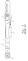
- FIG. 2 illustrates another conventional wrench 1b which also has a coupler 1b' on a driving head and a stem 4 coupled with an angle measurement device 5 which is electrically connected to a control system (not shown in the drawings) and a display device 6 through a transmission cable 5'.
- the angle measurement device 5 is formed to mate the profile of the stem 4 and can detect the turning angles input to the control system on the wrench 1b and displayed on the display device 6.
- the angle measurement device 5 has to be incorporated with specific wrench 1b, control system and display device 6 to be used. Compatibility and usability are lower, error probability is higher and the structure is more complex.
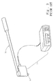
- An U.S. patent No. 5,589,644 discloses a wrench 1c for measuring turning angles, referring to FIG. 3 , which can detect turning angles of a coupler 1c' of a driving head of the wrench 1c through an angle detection system 7, and calibrate fastening tightness of a work piece according to the turning angles of the wrench.
- the angle detection system is applicable only to the specific wrench 1c and not adaptable to other tools or changeable in terms of use positions arbitrarily, hence results in a higher production cost, and also is more complicated in structure. Thus its usability is limited.
- FIG. 4 illustrates another embodiment of the wrench 1d for measuring turning angles according to U.S. patent No. 5,589,644 that has an angle detection system 8 to detect the turning angles of a coupler 1d' of the driving head thereof.
- the angle detection system is embedded in the wrench 1d and cannot be shared with other tools, thus its applicability also is limited.
- the primary object of the present invention is to provide an external-coupled electronic angle measurement apparatus mountable onto a wide variety of hand tools and enhance compatibility.
- the invention provides an external-coupled electronic angle measurement apparatus which comprises a housing, a coupling portion, an angle detection system and a display element.
- the coupling portion is located on the housing to fasten the external-coupled electronic angle measurement apparatus to a tool.
- the angle detection system is held in the housing to detect turning angles.
- the display element is electrically connected to the angle detection system to display the turning angles.
- the angle detection system can accurately measure the turning angles of a screw driven by the hand tool.
- the apparatus of the invention is installed on a hand tool 10 which has a driving bar 11 with a driving head 12 at one end and a sleeve coupling head 13 at one side of the driving head 12 to fasten a screw.
- the external-coupled electronic angle measurement apparatus includes a housing 20, a display unit 30, an angle detection system 40 and a coupling portion 50.
- the housing 20 has a holder 60 at the bottom.
- the coupling portion 50 is an adsorbable element and is fastened to the holder 60, thus the apparatus of the invention can be quickly and movably mounted onto the driving head 12 or the driving bar 11 or the hand tool 10 at a desired location.
- the angle detection system 40 is held in the housing 20 to detect turning angles of the sleeve coupling head 13, and includes an electronic angle measurement device 41 and a signal processing system 42, and is installed on a circuit board 43.
- the electronic angle measurement device 41 can be a gyroscope.
- the display element 30 is located on the housing 20 and electrically connected to the angle detection system 40 to display the turning angles of the sleeve coupling head 13.
- the coupling portion 50A can be a magnetic element.
- FIG. 9 shows yet another embodiment in which the coupling portion 50B can be a sucking disc.
- FIG. 10 shows one of other embodiments that the coupling portion 50C can be a gripper. Through adsorption of the s magnetic element or sucking disc, or clipping of the gripper, the external-coupled electronic angle measurement apparatus can be fastened on the driving head 12, driving bar 11 or hand tool 10 at a desired location.
- FIG. 11 illustrates another embodiment of the invention in which the coupling portion 50D can be at least one cavity to be wedged in by a mating boss or profile formed on the driving head 12, driving bar 11 or hand tool 10 at a desired location, thus the external-coupled electronic angle measurement apparatus can be fastened.
- FIG. 12 shows yet another embodiment in which the coupling portion 50D has screw threads 51 formed on the surface of the cavity to allow the apparatus to be fastened through a screw 52.
- FIG. 13 shows another embodiment in which the coupling portion 50E can be at least one boss to be wedged in a mating cavity 53 formed on the driving head 12, driving bar 11 or hand tool 10 at a desired location.
- the profiles of the boss and cavity 53 are not limited to the same, partially matched and mutually latched can hold the apparatus of the invention.
- FIG. 14 shows still another embodiment in which the coupling portion 50E has screw threads 54 formed on the surface of the boss to fasten the apparatus by screwing.
- FIG. 15 shows yet another embodiment in which the coupling portion 50F can be at least one through holes to receive a fastening element 99 to fasten the driving head 12, driving bar 11 or hand tool 10 at a desired location and to further fasten the external-coupled electronic angle measurement apparatus of the invention.
- FIGS. 16A through 16D illustrate other embodiments in which the coupling portion 50G includes two sets located at two opposite sides of the apparatus in an up and down, left and right, front and rear, or coaxial manner.
- the two sets of the coupling portion 50G at the two sides can be cavities both, bosses both or one cavity and one boss to be latched to fasten the driving head 12, driving bar 11 or hand tool 10 at a desired location and to further fasten the external-coupled electronic angle measurement apparatus in varying combinations.
- the turning angles of the hand tool 10 can be measured by the angle detection system 40, and the external-coupled electronic angle measurement apparatus of the present invention can be disassembled and fastened to the driving head 12, driving bar 11 or hand tool 10 at a desired location.
- the angle detection system 40 measures the turning angles of the sleeve coupling head 13.
Landscapes
- Engineering & Computer Science (AREA)
- Mechanical Engineering (AREA)
- Details Of Spanners, Wrenches, And Screw Drivers And Accessories (AREA)
Abstract
The present invention proposes an external-coupled electronic angle measurement apparatus installed on a hand tool (10) including a housing (20), a display element (30), an angle detection system (40) and a coupling portion (50). The housing (20) is movable through the coupling portion (50) to fasten the external-coupled electronic angle measurement apparatus to a desired location of the driving head (12), driving bar (11), sleeve coupling head (13) or hand tool (10) to accurately measure turning angles of a screw driven by the hand tool (10) through the angle detection system (40) and display the result on the display element (30).
Description
- The present invention relates to an external-coupled apparatus of a hand tool and particularly to an external-coupled measurement apparatus to measure turning angles of a hand tool.
- Please refer to
FIG. 1 , to measure the turning angles of a coupler 1a' on a driving head of a conventional wrench 1a, anangle gauge 2 is provided to couple with the coupler 1a'. Theangle gauge 2 has indication scales 3 to record the turning angles of the wrench 1a, and then the turning angles of the coupler 1a' can be known. Such an approach involves troublesome operation, and a greater error tends to be occurred. -
FIG. 2 illustrates another conventional wrench 1b which also has a coupler 1b' on a driving head and astem 4 coupled with anangle measurement device 5 which is electrically connected to a control system (not shown in the drawings) and adisplay device 6 through a transmission cable 5'. Theangle measurement device 5 is formed to mate the profile of thestem 4 and can detect the turning angles input to the control system on the wrench 1b and displayed on thedisplay device 6. Theangle measurement device 5 has to be incorporated with specific wrench 1b, control system anddisplay device 6 to be used. Compatibility and usability are lower, error probability is higher and the structure is more complex. - An
U.S. patent No. 5,589,644 discloses a wrench 1c for measuring turning angles, referring toFIG. 3 , which can detect turning angles of a coupler 1c' of a driving head of the wrench 1c through anangle detection system 7, and calibrate fastening tightness of a work piece according to the turning angles of the wrench. The angle detection system is applicable only to the specific wrench 1c and not adaptable to other tools or changeable in terms of use positions arbitrarily, hence results in a higher production cost, and also is more complicated in structure. Thus its usability is limited. -
FIG. 4 illustrates another embodiment of the wrench 1d for measuring turning angles according toU.S. patent No. 5,589,644 that has anangle detection system 8 to detect the turning angles of a coupler 1d' of the driving head thereof. The angle detection system is embedded in the wrench 1d and cannot be shared with other tools, thus its applicability also is limited. - Therefore, the primary object of the present invention is to provide an external-coupled electronic angle measurement apparatus mountable onto a wide variety of hand tools and enhance compatibility.
- The invention provides an external-coupled electronic angle measurement apparatus which comprises a housing, a coupling portion, an angle detection system and a display element. The coupling portion is located on the housing to fasten the external-coupled electronic angle measurement apparatus to a tool. The angle detection system is held in the housing to detect turning angles. The display element is electrically connected to the angle detection system to display the turning angles.
- Through the coupling portion, the invention can be easily and quickly installed on different hand tools with random profiles. The angle detection system can accurately measure the turning angles of a screw driven by the hand tool.
- The foregoing, as well as additional objects, features and advantages of the invention will be more readily apparent from the following detailed description, which proceeds with reference to the accompanying drawings.
-
-
FIG. 1 is a perspective view of a conventional wrench. -
FIG. 2 is a top view of another conventional wrench. -
FIG. 3 is a perspective view ofU.S. patent No. 5,589,644 . -
FIG. 4 is another perspective view ofU.S. patent No. 5,589,644 . -
FIG. 5 is a perspective view of the invention. -
FIG. 6 is an exploded view of the invention. -
FIG. 7 is a perspective view of an embodiment of the invention. -
FIG. 8 is a plane view of another embodiment of the invention. -
FIG. 9 is a plane view of yet another embodiment of the invention. -
FIGS. 10 through 16D are plane views of other embodiments of the invention. - Please refer to
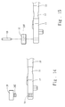
FIGS. 5 ,6 and7 for an embodiment of the invention. The apparatus of the invention is installed on ahand tool 10 which has adriving bar 11 with a drivinghead 12 at one end and asleeve coupling head 13 at one side of the drivinghead 12 to fasten a screw. The external-coupled electronic angle measurement apparatus includes ahousing 20, adisplay unit 30, anangle detection system 40 and acoupling portion 50. Thehousing 20 has aholder 60 at the bottom. Thecoupling portion 50 is an adsorbable element and is fastened to theholder 60, thus the apparatus of the invention can be quickly and movably mounted onto the drivinghead 12 or thedriving bar 11 or thehand tool 10 at a desired location. - The
angle detection system 40 is held in thehousing 20 to detect turning angles of thesleeve coupling head 13, and includes an electronicangle measurement device 41 and asignal processing system 42, and is installed on acircuit board 43. The electronicangle measurement device 41 can be a gyroscope. Thedisplay element 30 is located on thehousing 20 and electrically connected to theangle detection system 40 to display the turning angles of thesleeve coupling head 13. - Refer to
FIG. 8 for another embodiment of the invention. Thecoupling portion 50A can be a magnetic element.FIG. 9 shows yet another embodiment in which thecoupling portion 50B can be a sucking disc.FIG. 10 shows one of other embodiments that thecoupling portion 50C can be a gripper. Through adsorption of the s magnetic element or sucking disc, or clipping of the gripper, the external-coupled electronic angle measurement apparatus can be fastened on thedriving head 12, drivingbar 11 orhand tool 10 at a desired location. -
FIG. 11 illustrates another embodiment of the invention in which thecoupling portion 50D can be at least one cavity to be wedged in by a mating boss or profile formed on the drivinghead 12, drivingbar 11 orhand tool 10 at a desired location, thus the external-coupled electronic angle measurement apparatus can be fastened.FIG. 12 shows yet another embodiment in which thecoupling portion 50D hasscrew threads 51 formed on the surface of the cavity to allow the apparatus to be fastened through ascrew 52. -
FIG. 13 shows another embodiment in which thecoupling portion 50E can be at least one boss to be wedged in amating cavity 53 formed on the drivinghead 12, drivingbar 11 orhand tool 10 at a desired location. The profiles of the boss andcavity 53 are not limited to the same, partially matched and mutually latched can hold the apparatus of the invention.FIG. 14 shows still another embodiment in which thecoupling portion 50E hasscrew threads 54 formed on the surface of the boss to fasten the apparatus by screwing. -
FIG. 15 shows yet another embodiment in which thecoupling portion 50F can be at least one through holes to receive afastening element 99 to fasten thedriving head 12, drivingbar 11 orhand tool 10 at a desired location and to further fasten the external-coupled electronic angle measurement apparatus of the invention. -
FIGS. 16A through 16D illustrate other embodiments in which thecoupling portion 50G includes two sets located at two opposite sides of the apparatus in an up and down, left and right, front and rear, or coaxial manner. The two sets of thecoupling portion 50G at the two sides can be cavities both, bosses both or one cavity and one boss to be latched to fasten thedriving head 12, drivingbar 11 orhand tool 10 at a desired location and to further fasten the external-coupled electronic angle measurement apparatus in varying combinations. - As a conclusion, the turning angles of the
hand tool 10 can be measured by theangle detection system 40, and the external-coupled electronic angle measurement apparatus of the present invention can be disassembled and fastened to the drivinghead 12, drivingbar 11 orhand tool 10 at a desired location. When thehand tool 10 is turned, theangle detection system 40 measures the turning angles of thesleeve coupling head 13. Hence when measuring the turning angles is desired, fasten the apparatus of the invention on thedriving head 12, driving bar orhand tool 10 at a desired location, and easily disassemble the apparatus to be stored when not in use. Such a structure provides greater adaptability and usability, and is easier to store and applicable to various types of hand tools to meet requirements of users.
Claims (15)
- An external-coupled electronic angle measurement apparatus, characterized by:a housing (20);a coupling portion (50) mounted onto the housing (20) to fasten the external-coupled electronic angle measurement apparatus to a hand tool (10);an angle detection system (40) held in the housing (20) to detect turning angles; anda display element (30) electrically connected to the angle detection system (40) to display the turning angles.
- The external-coupled electronic angle measurement apparatus of claim 1, wherein the coupling portion (50) is an adsorbable element.
- The external-coupled electronic angle measurement apparatus of claim 1, wherein the coupling portion (50A) is a magnetic element.
- The external-coupled electronic angle measurement apparatus of claim 3, wherein the magnetic element is a magnet.
- The external-coupled electronic angle measurement apparatus of claim 1, wherein the coupling portion (50B) is a sucking disc.
- The external-coupled electronic angle measurement apparatus of claim 1, wherein the coupling portion (50C) is a gripper.
- The external-coupled electronic angle measurement apparatus of claim 1, wherein the coupling portion (50D) is a cavity.
- The external-coupled electronic angle measurement apparatus of claim 7, wherein the cavity includes screw threads (51).
- The external-coupled electronic angle measurement apparatus of claim 1, wherein the coupling portion (50E) is a boss.
- The external-coupled electronic angle measurement apparatus of claim 9, wherein the boss includes screw threads (54).
- The external-coupled electronic angle measurement apparatus of claim 1, wherein the coupling portion (50F) is a through hole.
- The external-coupled electronic angle measurement apparatus of claim 1, wherein the coupling portion (50G) includes two sets located on two opposite sides of the external-coupled electronic angle measurement apparatus.
- The external-coupled electronic angle measurement apparatus of claim 12, wherein the two sets of the coupling portion (50G) are positioned coaxially.
- The external-coupled electronic angle measurement apparatus of claim 13, wherein two sets of the coupling portion (50G) are respectively a cavity and a boss.
- The external-coupled electronic angle measurement apparatus of claim 1, wherein the angle detection system (40) includes a signal processing system (42) and an electronic angle measurement device (41) which is a gyroscope.
Priority Applications (1)
| Application Number | Priority Date | Filing Date | Title |
|---|---|---|---|
| EP10165326A EP2394792A1 (en) | 2010-06-09 | 2010-06-09 | External-coupled electronic angle measurement apparatus |
Applications Claiming Priority (1)
| Application Number | Priority Date | Filing Date | Title |
|---|---|---|---|
| EP10165326A EP2394792A1 (en) | 2010-06-09 | 2010-06-09 | External-coupled electronic angle measurement apparatus |
Publications (1)
| Publication Number | Publication Date |
|---|---|
| EP2394792A1 true EP2394792A1 (en) | 2011-12-14 |
Family
ID=43085684
Family Applications (1)
| Application Number | Title | Priority Date | Filing Date |
|---|---|---|---|
| EP10165326A Ceased EP2394792A1 (en) | 2010-06-09 | 2010-06-09 | External-coupled electronic angle measurement apparatus |
Country Status (1)
| Country | Link |
|---|---|
| EP (1) | EP2394792A1 (en) |
Cited By (3)
| Publication number | Priority date | Publication date | Assignee | Title |
|---|---|---|---|---|
| US8886492B2 (en) | 2011-09-23 | 2014-11-11 | Brown Line Metal Works, Llc | Digital angle meter |
| US8918292B2 (en) | 2011-09-23 | 2014-12-23 | Brown Line Metalworks, Llc | Digital angle meter |
| EP2857147A1 (en) * | 2013-10-04 | 2015-04-08 | Brown Line Metal Works, LLC | Digital angle meter |
Citations (8)
| Publication number | Priority date | Publication date | Assignee | Title |
|---|---|---|---|---|
| WO1996016761A1 (en) * | 1994-12-01 | 1996-06-06 | Snap-On Incorporated | Torque-angle wrench |
| DE29622317U1 (en) * | 1996-12-21 | 1997-11-27 | Eduard Wille Gmbh & Co, 42349 Wuppertal | Operating tool for tightening screw connection parts with an angle measuring device |
| US6244778B1 (en) * | 1999-01-21 | 2001-06-12 | Richard M. Chesbrough | Universal suction-based connection device |
| US20030065474A1 (en) * | 2001-09-28 | 2003-04-03 | Spx Corporation | Apparatus and method for sensing torque angle |
| DE202004017472U1 (en) * | 2004-11-10 | 2005-01-05 | Hazet-Werk Hermann Zerver Gmbh & Co. Kg | Torque wrench with angle indicator has a multi pole magnetic sensor system fitted to the tool bit holder and with a connection to a display |
| DE202007002793U1 (en) * | 2007-02-22 | 2007-05-10 | Eduard Wille Gmbh & Co. Kg | Angle measuring device |
| DE102007055028A1 (en) * | 2007-11-17 | 2009-05-20 | Richard Abr. Herder Kg | Tool e.g. wrench, for motor vehicle, has angle measuring unit connected with actuating element and/or operating element by connection element, where connection between actuating element and/or operating element is detachable |
| EP2147751A1 (en) * | 2008-07-23 | 2010-01-27 | Beta Utensili S.p.A. | Method and electronic accessory for angular fastening of a nut or bolt |
-
2010
- 2010-06-09 EP EP10165326A patent/EP2394792A1/en not_active Ceased
Patent Citations (9)
| Publication number | Priority date | Publication date | Assignee | Title |
|---|---|---|---|---|
| WO1996016761A1 (en) * | 1994-12-01 | 1996-06-06 | Snap-On Incorporated | Torque-angle wrench |
| US5589644A (en) | 1994-12-01 | 1996-12-31 | Snap-On Technologies, Inc. | Torque-angle wrench |
| DE29622317U1 (en) * | 1996-12-21 | 1997-11-27 | Eduard Wille Gmbh & Co, 42349 Wuppertal | Operating tool for tightening screw connection parts with an angle measuring device |
| US6244778B1 (en) * | 1999-01-21 | 2001-06-12 | Richard M. Chesbrough | Universal suction-based connection device |
| US20030065474A1 (en) * | 2001-09-28 | 2003-04-03 | Spx Corporation | Apparatus and method for sensing torque angle |
| DE202004017472U1 (en) * | 2004-11-10 | 2005-01-05 | Hazet-Werk Hermann Zerver Gmbh & Co. Kg | Torque wrench with angle indicator has a multi pole magnetic sensor system fitted to the tool bit holder and with a connection to a display |
| DE202007002793U1 (en) * | 2007-02-22 | 2007-05-10 | Eduard Wille Gmbh & Co. Kg | Angle measuring device |
| DE102007055028A1 (en) * | 2007-11-17 | 2009-05-20 | Richard Abr. Herder Kg | Tool e.g. wrench, for motor vehicle, has angle measuring unit connected with actuating element and/or operating element by connection element, where connection between actuating element and/or operating element is detachable |
| EP2147751A1 (en) * | 2008-07-23 | 2010-01-27 | Beta Utensili S.p.A. | Method and electronic accessory for angular fastening of a nut or bolt |
Cited By (3)
| Publication number | Priority date | Publication date | Assignee | Title |
|---|---|---|---|---|
| US8886492B2 (en) | 2011-09-23 | 2014-11-11 | Brown Line Metal Works, Llc | Digital angle meter |
| US8918292B2 (en) | 2011-09-23 | 2014-12-23 | Brown Line Metalworks, Llc | Digital angle meter |
| EP2857147A1 (en) * | 2013-10-04 | 2015-04-08 | Brown Line Metal Works, LLC | Digital angle meter |
Similar Documents
| Publication | Publication Date | Title |
|---|---|---|
| US6131299A (en) | Display device for a coordinate measurement machine | |
| US8215187B2 (en) | Torque detection device | |
| US5657550A (en) | Hand-held gap and contour measuring gauge | |
| US8347515B2 (en) | External-coupled electronic angle measurement apparatus | |
| US20120119919A1 (en) | Multifunctional torque detection device | |
| JP6313848B2 (en) | Fixing load confirmation tester | |
| US9631913B2 (en) | Calibration control device for metrology tools | |
| JP3189084U (en) | Electronic torque wrench | |
| EP2394792A1 (en) | External-coupled electronic angle measurement apparatus | |
| US12220793B2 (en) | Clamping tool with interchangeable arm | |
| US20090249924A1 (en) | Torque-Indicating Extensive Apparatus | |
| CN101094588B (en) | Detection fixture | |
| US20150172788A1 (en) | Wireless Connective Apparatus | |
| CN212255402U (en) | Interface Fixtures and Test Equipment | |
| TWM322861U (en) | Digital torsional wrench | |
| JP5694688B2 (en) | External digital angle measuring device | |
| CN107037244B (en) | Probe fixing and guiding structure of electronic component testing device | |
| CN104148697A (en) | Hand tool machine | |
| JP3129072U (en) | Magnetic pole judgment device | |
| JP2005121527A (en) | Measuring device of torque tool | |
| WO2024045123A1 (en) | Dongle for an electronic torque wrench | |
| CN221630609U (en) | Bolt ball diameter detection device | |
| CN212620573U (en) | Gap measuring device for rail transit vehicle | |
| US12151343B2 (en) | Torque application tool | |
| KR200227621Y1 (en) | Digital vernier calipers |
Legal Events
| Date | Code | Title | Description |
|---|---|---|---|
| 17P | Request for examination filed |
Effective date: 20110812 |
|
| AK | Designated contracting states |
Kind code of ref document: A1 Designated state(s): AL AT BE BG CH CY CZ DE DK EE ES FI FR GB GR HR HU IE IS IT LI LT LU LV MC MK MT NL NO PL PT RO SE SI SK SM TR |
|
| AX | Request for extension of the european patent |
Extension state: BA ME RS |
|
| PUAI | Public reference made under article 153(3) epc to a published international application that has entered the european phase |
Free format text: ORIGINAL CODE: 0009012 |
|
| 17Q | First examination report despatched |
Effective date: 20121123 |
|
| STAA | Information on the status of an ep patent application or granted ep patent |
Free format text: STATUS: THE APPLICATION HAS BEEN REFUSED |
|
| 18R | Application refused |
Effective date: 20160904 |