EP2394581A1 - Providing an elastic image in an ultrasound system - Google Patents
Providing an elastic image in an ultrasound system Download PDFInfo
- Publication number
- EP2394581A1 EP2394581A1 EP20110168935 EP11168935A EP2394581A1 EP 2394581 A1 EP2394581 A1 EP 2394581A1 EP 20110168935 EP20110168935 EP 20110168935 EP 11168935 A EP11168935 A EP 11168935A EP 2394581 A1 EP2394581 A1 EP 2394581A1
- Authority
- EP
- European Patent Office
- Prior art keywords
- frame
- displacement
- strain
- calculate
- ultrasound data
- Prior art date
- Legal status (The legal status is an assumption and is not a legal conclusion. Google has not performed a legal analysis and makes no representation as to the accuracy of the status listed.)
- Granted
Links
Images





Classifications
-
- A—HUMAN NECESSITIES
- A61—MEDICAL OR VETERINARY SCIENCE; HYGIENE
- A61B—DIAGNOSIS; SURGERY; IDENTIFICATION
- A61B8/00—Diagnosis using ultrasonic, sonic or infrasonic waves
- A61B8/48—Diagnostic techniques
- A61B8/485—Diagnostic techniques involving measuring strain or elastic properties
-
- A—HUMAN NECESSITIES
- A61—MEDICAL OR VETERINARY SCIENCE; HYGIENE
- A61B—DIAGNOSIS; SURGERY; IDENTIFICATION
- A61B5/00—Measuring for diagnostic purposes; Identification of persons
- A61B5/0048—Detecting, measuring or recording by applying mechanical forces or stimuli
-
- A—HUMAN NECESSITIES
- A61—MEDICAL OR VETERINARY SCIENCE; HYGIENE
- A61B—DIAGNOSIS; SURGERY; IDENTIFICATION
- A61B5/00—Measuring for diagnostic purposes; Identification of persons
- A61B5/0048—Detecting, measuring or recording by applying mechanical forces or stimuli
- A61B5/0053—Detecting, measuring or recording by applying mechanical forces or stimuli by applying pressure, e.g. compression, indentation, palpation, grasping, gauging
-
- A—HUMAN NECESSITIES
- A61—MEDICAL OR VETERINARY SCIENCE; HYGIENE
- A61B—DIAGNOSIS; SURGERY; IDENTIFICATION
- A61B8/00—Diagnosis using ultrasonic, sonic or infrasonic waves
- A61B8/08—Clinical applications
- A61B8/0833—Clinical applications involving detecting or locating foreign bodies or organic structures
-
- G—PHYSICS
- G01—MEASURING; TESTING
- G01S—RADIO DIRECTION-FINDING; RADIO NAVIGATION; DETERMINING DISTANCE OR VELOCITY BY USE OF RADIO WAVES; LOCATING OR PRESENCE-DETECTING BY USE OF THE REFLECTION OR RERADIATION OF RADIO WAVES; ANALOGOUS ARRANGEMENTS USING OTHER WAVES
- G01S7/00—Details of systems according to groups G01S13/00, G01S15/00, G01S17/00
- G01S7/52—Details of systems according to groups G01S13/00, G01S15/00, G01S17/00 of systems according to group G01S15/00
- G01S7/52017—Details of systems according to groups G01S13/00, G01S15/00, G01S17/00 of systems according to group G01S15/00 particularly adapted to short-range imaging
- G01S7/52023—Details of receivers
- G01S7/52036—Details of receivers using analysis of echo signal for target characterisation
- G01S7/52042—Details of receivers using analysis of echo signal for target characterisation determining elastic properties of the propagation medium or of the reflective target
Definitions
- the present disclosure generally relates to ultrasound systems, and more particularly to providing an elastic image in an ultrasound system.
- the ultrasound image is displayed in a Brightness mode (B-mode) by using reflectivity caused by an acoustic impedance difference between the tissues of a target object.
- B-mode Brightness mode
- an ultrasound elastic imaging technology has been developed to display an image of the target object by using mechanical characteristics of the target object. Such technology is very helpful for diagnosing lesions such as cancers.
- the tumor or cancer is relatively stiffer than the neighboring tissues. Thus, when pressure is uniformly applied, a variation of the tumor or cancer is typically smaller than those of the neighboring tissues.
- the elasticity of a tissue is measured by using ultrasound data obtained before and after applying the pressure to the tissue.
- a compression plate mounted on an ultrasound probe may be used to apply the pressure to the tissue.
- a user may press the compression plate on the target object, thereby applying the pressure to the tissues of the target object.
- strain data in the tissues may vary according to the pressure applied by the user.
- the video quality of an elastic image may be changed according to the pressure applied to the tissue.
- an ultrasound system comprises: an ultrasound data acquisition unit configured to transmit and receive ultrasound signals to and from a living body to output ultrasound data corresponding to a plurality of frames while applying compression to the living body; and a processing unit in communication with the ultrasound data acquisition unit, the processing unit being configured to extract frames from a (n-1) th frame to a (n-i) th frame on a basis of a n th frame, wherein n indicates an integer larger than one and i indicates a positive integer, detect an optimal frame for forming an elastic image among the extracted frames by using first displacement between the n th frame and each of the extracted frames based on the ultrasound data, calculate second displacement between the optimal frame and the n th frame based on the ultrasound data, and form the elastic image based on the second displacement.
- a method of providing an elastic image comprising: a) transmitting and receiving ultrasound signals to and from a living body to output ultrasound data corresponding to a plurality of frames while applying compression to the living body; b) extracting frames from a (n-1) th frame to a (n-i) th frame on a basis of a n th frame, wherein n indicates an integer larger than one and i indicates a positive integer; c) detecting an optimal frame for forming an elastic image among the extracted frames by using first displacement between the n th frame and each of the extracted frames based on the ultrasound data; d) calculating second displacement between the optimal frame and the n th frame based on the ultrasound data; and e) forming the elastic image based on the second displacement.
- an ultrasound system 100 in accordance with an illustrative embodiment is shown.
- the ultrasound system 100 includes an ultrasound data acquisition unit 110.
- the ultrasound data acquisition unit 110 is configured to transmit and receive ultrasound signals to and from a living body while applying compression to the target object, and output ultrasound data.
- the living body includes a plurality of target objects (e.g., blood vessels, a heart, a lesion etc.).
- FIG. 2 is a block diagram showing an illustrative embodiment of the ultrasound data acquisition unit 110.
- the ultrasound data acquisition unit 110 includes an ultrasound probe 210, a transmit (Tx) signal generating section 220, a beam former 230 and an ultrasound data forming section 240.
- the ultrasound probe 210 applies the compression provided from an external to the living body.
- the ultrasound probe 210 includes a plurality of elements (not shown) for reciprocally converting between ultrasound signals and electrical signals.
- the ultrasound probe 210 is configured to transmit ultrasound signals to the living body.
- the ultrasound probe 210 is further configured to receive ultrasound signals (i.e., ultrasound echo signals) from the living body and output electrical signals ("received signals").
- the received signals are analog signals.
- the ultrasound probe 210 includes a convex probe, a linear probe and the like.
- the Tx signal generating section 220 is configured to control the transmission of the ultrasound signals.
- the Tx signal generating section 220 is further configured to generate electrical signals ("Tx signals") in consideration of the elements and focal points.
- the Tx signal generating section 220 generates Tx signals for obtaining a plurality of frames F; (1 ⁇ i ⁇ N) while applying compression to the living body, as shown in FIG. 3 .
- the ultrasound probe 210 converts the Tx signals provided from the Tx signal generating section 220 into the ultrasound signals, transmit the ultrasound signals to the living body and receive the ultrasound echo signals from the living body to thereby output the received signals.
- the frame includes a brightness mode image. However, it should be noted herein that the frame may not be limited thereto.
- the beam former 230 is configured to convert the received signals provided from the ultrasound probe 210 into digital signals.
- the beam former 230 is further configured to apply delays to the digital signals in consideration of the elements and the focal points to output digital receive-focused signals.
- the ultrasound data forming section 240 is configured to form ultrasound data based on the digital receive-focused signals provided from the beam former 230.
- the ultrasound data includes radio frequency data. However, it should be noted herein that the ultrasound data may not be limited thereto.
- the ultrasound data forming section 240 is further configured to perform various signal processing (e.g., gain adjustment) upon the digital receive-focused signals. In one embodiment, the ultrasound data forming section 240 forms the ultrasound data corresponding to each of the frames F i (1 ⁇ i ⁇ N) based on the digital receive-focused signals provided from the beam former 230.
- the ultrasound system 100 further includes a processing unit 120 in communication with the ultrasound data acquisition unit 110.
- the processing unit 120 includes a central processing unit, a microprocessor or a graphic processing unit. However, it should be noted herein that the processing unit 120 may not be limited thereto.
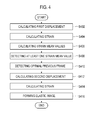
- FIG. 4 is a flow chart showing a process of forming an elastic image in accordance with a first embodiment.
- the processing unit 120 is configured to calculate displacement ("first displacement") based on the ultrasound data corresponding to a current frame and the ultrasound data corresponding to a predetermined number of previous frames, at step S402 in FIG. 4 .
- the first displacement is roughly calculated.
- the displacement D i - 1 corresponding to an elastic image E ⁇ - 1 between a current frame F i and a previous frame F ⁇ - 1 was calculated based on the ultrasound data provided from the ultrasound data acquisition unit 110, as shown in FIG. 5 .
- the processing unit 120 is configured to extract the predetermined number of the previous frames based on the current frame.
- the processing unit 120 is further configured to calculate the first displacement corresponding to the elastic images between the current frame and each of the previous frames based on the ultrasound data.
- the processing unit 120 is configured to extract the predetermined number of the previous frames F i - 1 to F i - 6 based on the current frame F i , as shown in FIG. 6 .
- the processing unit 120 is further configured to calculate the first displacement D i - 1 to D i - 6 corresponding to the elastic images E i - 1 to E i - 6 between the current frame F i and each of the previous frames F i - 1 to F i - 6 based on the ultrasound data, as shown in FIG. 6 .
- the processing unit 120 is configured to extract the predetermined number of the previous frames F i - 1 to F i - 6 based on the current frame F i .
- the processing unit 120 is further configured to set a region of interest ("ROI") on the current frame F i and the extracted previous frames F i - I to F i - 6 .
- the processing unit 120 is further configured to calculate the first displacements between the ROI of the current frame F; and the ROI of each of the extracted previous frames F i - 1 to Fi- 6 .
- ROI region of interest
- the processing unit 120 is configured to extract the predetermined number of the previous frames F i - 1 to Fi- 6 based on the current frame F;.
- the processing unit 120 is further configured to calculate axial motions corresponding to the elastic images E i - 1 to E i - 6 between the current frame F i and each of the previous frames Fi- I to F;- 6 .
- the methods of calculating the axial motion e.g., blocking matching
- the processing unit 120 is further configured to calculate the first displacement D i-1 to D;- 6 corresponding to the elastic images E i-1 to E;- 6 based on the calculated axial motions.
- the processing unit 120 is configured to extract the predetermined number of the previous frames F i - 1 to F;- 6 based on the current frame F;.
- the processing unit 120 is further configured to set the ROI on the current frame F; and the previous frames F i - 1 to F;- 6 .
- the processing unit 120 is also configured to calculate the axial motions corresponding to the elastic images E i-1 to E i-6 between the current frame F; and each of the previous frames F i-1 to F;- 6 .
- the processing unit 120 is further configured to calculate the first displacement D i - 1 to D i - 6 corresponding to the elastic images E i - I to E i - 6 based on the calculated axial motions.
- the processing unit 120 is configured to calculate strain corresponding to each of the elastic images based on the first displacement, at step S404 in FIG. 4 .
- the methods of calculating the strain are well known in the art. For example, the processing unit 120 calculates a differential value of the first displacement as the strain.
- the processing unit 120 is configured to calculate a strain mean value corresponding to each of the elastic images based on the calculated strain, at step S406 in FIG. 4 .
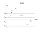
- the processing unit 120 is configured to compare the calculated strain mean values with a predetermined strain threshold range to detect at least one strain mean value corresponding to the strain threshold range, at step S408 in FIG. 4 .
- the processing unit 120 compares each of the strain mean values S i-1 to S i - 6 with the strain threshold range S min to S max to detect strain mean values S i-2 , S i-3 and Si- 6 , which are comprised in the strain threshold range S mm to S max , as shown in FIG. 7 .
- the processing unit 120 is configured to detect an optimal previous frame for forming an optimal elastic image from at least one previous frame corresponding to the at least one strain mean value, at step 5410 in FIG. 4 .
- the processing unit 120 calculates standard deviation of the strain for the previous frames F;- 2 , F;- 3 and F;- 6 corresponding to the detected strain mean values S i - 2 , S i - 3 and S i - 6 .
- the processing unit 120 further extracts a previous frame (e.g., F i-3 ) corresponding to minimum standard deviation as the optimal.
- the processing unit 120 detects the previous frame corresponding to the minimum standard deviation as the optimal previous frame for forming the elastic image
- the processing unit 120 further detects the previous frame corresponding to a strain mean value, which is closest to a predetermined threshold in the strain threshold range, as the optimal previous frame.
- the processing unit 120 detects the previous frame corresponding to a strain mean value, which is smaller than or larger than the predetermined threshold in the strain threshold range, as the optima previous frame.
- the processing unit 120 is configured to calculate displacement ("second displacement") between the optimal previous frame and the current frame based on the ultrasound data provided from the ultrasound data acquisition unit 110, at step 5412 in FIG. 4 .
- the processing unit 120 calculates the second displacement between the optimal previous frame F i - 3 and the current frame F i based on the ultrasound data provided from the ultrasound data acquisition unit 110.
- the processing unit 120 is configured to calculate the strain based on the second displacement, at step S414 in FIG. 4 .
- the processing unit 120 is configured to form the optimal elastic image based on the strain, at step 5416 in FIG. 4 .
- the methods of forming the elastic image based on the strain are well known in the art. Thus, they have not been described in detail so as not to unnecessarily obscure the present invention.
- FIG. 8 is a flow chart showing a process of forming an elastic image in accordance with a second embodiment.
- the processing unit 120 is configured to extract a predetermined number of previous frames based on a current frame, at step S802 in FIG. 8 .
- the processing unit 120 is configured to perform motion tracking (e.g., block matching) between the current frame and each of the extracted previous frames to detect lateral motion between the current first frame and each of the previous first frames, at step S804 in FIG. 8 .
- motion tracking e.g., block matching
- the processing unit 120 is configured to detect an optimal previous frame for forming an optimal elastic image from the extracted previous frames, at step S806 in FIG. 8 .
- the processing unit 120 compares the detected lateral motion to detect a previous frame corresponding to minimum lateral motion.
- the processing unit 120 further sets the detected previous frame as the optimal previous frame.
- the processing unit 120 detects the lateral motion between the current frame and the previous frame
- the processing unit 120 further detects elevation motion between a current three-dimensional frame and a previous three-dimensional frame.
- the three-dimensional frame includes a three-dimensional image.
- the three-dimensional frame may not be limited thereto.
- the processing unit 120 is configured to calculate strain between the current frame and the optimal previous frame based on the ultrasound data provided from the ultrasound data acquisition unit 110, at step S808 in FIG. 8 .
- the processing unit 120 is configured to form the optimal elastic image based on the calculated strain, at step S810 in FIG. 8 .
- FIG. 9 is a flow chart showing a process of forming an elastic image in accordance with a third embodiment.
- the processing unit 120 is configured to calculate the first displacement based on the ultrasound data corresponding to the current frame and the ultrasound data corresponding to the predetermined number of previous frames, at step S902 in FIG. 9 .
- the step S902 in FIG. 9 is similar to the step S402 in FIG. 4 . Thus, it has not been described in detail.
- the processing unit 120 is configured to calculate the strain corresponding to each of the elastic images based on the first displacement, at step S904 in FIG. 9 .
- the processing unit 120 is configured to calculate the strain mean value corresponding to each of the elastic images based on the calculated strain, at step S906 in FIG. 9 .
- the step S906 in FIG. 9 is similar to the step S406 in FIG. 4 . Thus, it has not been described in detail.
- the processing unit 120 is configured to compare the calculated strain mean values with the strain threshold range to detect at least one strain mean value corresponding to the strain threshold range, at step S908 in FIG. 9 .
- the processing unit 120 is configured to perform the motion tracking (e.g., block matching) between the current frame and at least one previous frame corresponding to the at least one strain mean value to detect the lateral motion between the current frame and the at least one previous frame, at step S910 in FIG. 9 .
- the motion tracking e.g., block matching
- the processing unit 120 detects the lateral motion between the current frame and the previous frame
- the processing unit 120 further detects the elevation motion between a current three-dimensional frame and a previous three-dimensional frame.
- the three-dimensional frame includes a three-dimensional image.
- the three-dimensional frame may not be limited thereto.
- the processing unit 120 is configured to detect the optimal previous frame for forming an optimal elastic image, ate step S912 in FIG. 9 . For example, the processing unit 120 compares the detected lateral motion to detect a previous frame corresponding to minimum lateral motion. The processing unit 120 further sets the detected previous frame as the optimal previous frame.
- the processing unit 120 is configured to calculate second displacement between the optimal previous frame and the current frame based on the ultrasound data provided from the ultrasound data acquisition unit 110, at step S914 in FIG. 9 .
- the processing unit 120 is configured to calculate the strain based on the second displacement, at step S914 in FIG. 9 .
- the processing unit 120 is configured to form the optimal elastic image based on the strain, at step S916 in FIG. 9 .
- FIG. 10 is a flow chart showing a process of forming an elastic image in accordance with a fourth embodiment.
- the processing unit 120 is configured to calculate the first displacement based on the ultrasound data corresponding to the current frame and the ultrasound data corresponding to the predetermined number of previous frames, at step S1002 in FIG. 10 .
- the step S1002 in FIG. 10 is similar to the step S402 in FIG. 4 . Thus, it has not been described in detail.
- the processing unit 120 is configured to calculate a displacement mean value corresponding to each of the elastic images based on the displacement, at step S1004 in FIG. 10 .
- the processing unit 120 is configured to compare the displacement mean values with a predetermined displacement threshold range to detect at least one displacement mean value corresponding to the displacement threshold range, at step S1006 in FIG. 10 .
- the step S1006 in FIG. 10 is similar to the step S408 in FIG. 4 . Thus, it has not been described in detail.
- the processing unit 120 is configured to detect the optimal previous frame for forming an optimal elastic image, at step S1008 in FIG. 10 . For example, the processing unit 120 calculates standard deviation of the strain for at least one previous frames corresponding to the at least one displacement mean value. The processing unit 120 further compares the calculated standard deviation to extract a previous frame corresponding to a minimum standard deviation. The processing unit 120 further sets the extracted previous frame as the optimal previous frame.
- the processing unit 120 detects the previous frame corresponding to the minimum standard deviation as the optimal previous frame for forming the elastic image
- the processing unit 120 further detects the previous frame corresponding to a displacement mean value, which is closest to a predetermined threshold in the displacement threshold range, as the optimal previous frame, or detect the previous frame corresponding to a displacement mean value, which is smaller than or larger than the threshold in the displacement threshold range, as the optima previous frame.
- the processing unit 120 is configured to calculate second displacement between the optimal previous frame and the current frame based on the ultrasound data provided from the ultrasound data acquisition unit 110, at step S1010 in FIG. 10 .
- the processing unit 120 is configured to calculate the strain based on the second displacement, at step S 1012 in FIG. 10 .
- the processing unit 120 is configured to form the optimal elastic image based on the strain, at step S 1014 in FIG. 10 .
- the ultrasound system 100 further includes a storage unit 130.
- the storage unit 130 stores the ultrasound data acquired by the ultrasound data acquisition unit 110.
- the storage unit 130 further stores the displacement and the strain calculated by the processing unit 120.
- the ultrasound system 100 further includes a display unit 140.
- the display unit 140 displays the elastic image formed by the processing unit 120.
- the display unit 140 further displays the frames formed by the processing unit 120.
Landscapes
- Health & Medical Sciences (AREA)
- Life Sciences & Earth Sciences (AREA)
- Engineering & Computer Science (AREA)
- Physics & Mathematics (AREA)
- Medical Informatics (AREA)
- Animal Behavior & Ethology (AREA)
- Veterinary Medicine (AREA)
- Public Health (AREA)
- Biomedical Technology (AREA)
- Heart & Thoracic Surgery (AREA)
- Biophysics (AREA)
- Molecular Biology (AREA)
- Surgery (AREA)
- Pathology (AREA)
- General Health & Medical Sciences (AREA)
- Nuclear Medicine, Radiotherapy & Molecular Imaging (AREA)
- Radiology & Medical Imaging (AREA)
- Computer Networks & Wireless Communication (AREA)
- General Physics & Mathematics (AREA)
- Radar, Positioning & Navigation (AREA)
- Remote Sensing (AREA)
- Ultra Sonic Daignosis Equipment (AREA)
Abstract
Description
- The present application claims priority from Korean Patent Application No.
10-2010-0054143 filed on June 9, 2010 - The present disclosure generally relates to ultrasound systems, and more particularly to providing an elastic image in an ultrasound system.
- Recently, an ultrasound system has been extensively used in the medical field due to its non-invasive and non-destructive nature. Modem high-performance ultrasound imaging systems and techniques are commonly used to produce two and three-dimensional ultrasound images of internal features of patients.
- Generally, the ultrasound image is displayed in a Brightness mode (B-mode) by using reflectivity caused by an acoustic impedance difference between the tissues of a target object. However, if the reflectivity of the target object is hardly different from those of the neighboring tissues such as tumor, cancer or the like, then it is not easy to recognize the target object in the B-mode image. Further, an ultrasound elastic imaging technology has been developed to display an image of the target object by using mechanical characteristics of the target object. Such technology is very helpful for diagnosing lesions such as cancers. The tumor or cancer is relatively stiffer than the neighboring tissues. Thus, when pressure is uniformly applied, a variation of the tumor or cancer is typically smaller than those of the neighboring tissues.
- The elasticity of a tissue is measured by using ultrasound data obtained before and after applying the pressure to the tissue. A compression plate mounted on an ultrasound probe may be used to apply the pressure to the tissue. A user may press the compression plate on the target object, thereby applying the pressure to the tissues of the target object. In such a case, strain data in the tissues may vary according to the pressure applied by the user. Thus, the video quality of an elastic image may be changed according to the pressure applied to the tissue.
- Embodiments for forming an elastic image in an ultrasound system are disclosed herein. In one embodiment, by way of non-limiting example, an ultrasound system comprises: an ultrasound data acquisition unit configured to transmit and receive ultrasound signals to and from a living body to output ultrasound data corresponding to a plurality of frames while applying compression to the living body; and a processing unit in communication with the ultrasound data acquisition unit, the processing unit being configured to extract frames from a (n-1)th frame to a (n-i)th frame on a basis of a nth frame, wherein n indicates an integer larger than one and i indicates a positive integer, detect an optimal frame for forming an elastic image among the extracted frames by using first displacement between the nth frame and each of the extracted frames based on the ultrasound data, calculate second displacement between the optimal frame and the nth frame based on the ultrasound data, and form the elastic image based on the second displacement.
- In another embodiment, there is provided a method of providing an elastic image, comprising: a) transmitting and receiving ultrasound signals to and from a living body to output ultrasound data corresponding to a plurality of frames while applying compression to the living body; b) extracting frames from a (n-1)th frame to a (n-i)th frame on a basis of a nth frame, wherein n indicates an integer larger than one and i indicates a positive integer; c) detecting an optimal frame for forming an elastic image among the extracted frames by using first displacement between the nth frame and each of the extracted frames based on the ultrasound data; d) calculating second displacement between the optimal frame and the nth frame based on the ultrasound data; and e) forming the elastic image based on the second displacement.
- The Summary is provided to introduce a selection of concepts in a simplified form that are further described below in the Detailed Description. This Summary is not intended to identify key or essential features of the claimed subject matter, nor is it intended to be used in determining the scope of the claimed subject matter.
-
-
FIG. 1 is a block diagram showing an illustrative embodiment of an ultrasound system. -
FIG. 2 is a block diagram showing an illustrative embodiment of an ultrasound data acquisition unit. -
FIG. 3 is a schematic diagram showing an example of frames. -
FIG. 4 is a flow chart showing a process of forming an elastic image in accordance with a first embodiment. -
FIG. 5 is a schematic diagram showing an example of calculating displacement. -
FIG. 6 is a schematic diagram showing an example of calculating the displacement in accordance with the embodiment. -
FIG. 7 is a schematic diagram showing an example of a strain threshold range. -
FIG. 8 is a flow chart showing a process of forming the elastic image in accordance with the second embodiment. -
FIG. 9 is a flow chart showing a process of forming an elastic image in accordance with a third embodiment. -
FIG. 10 is a flow chart showing a process of forming an elastic image in accordance with a fourth embodiment. - A detailed description may be provided with reference to the accompanying drawings. One of ordinary skill in the art may realize that the following description is illustrative only and is not in any way limiting.
- Referring to
FIG. 1 , anultrasound system 100 in accordance with an illustrative embodiment is shown. As depicted therein, theultrasound system 100 includes an ultrasounddata acquisition unit 110. The ultrasounddata acquisition unit 110 is configured to transmit and receive ultrasound signals to and from a living body while applying compression to the target object, and output ultrasound data. The living body includes a plurality of target objects (e.g., blood vessels, a heart, a lesion etc.). -
FIG. 2 is a block diagram showing an illustrative embodiment of the ultrasounddata acquisition unit 110. Referring toFIG. 2 , the ultrasounddata acquisition unit 110 includes anultrasound probe 210, a transmit (Tx) signal generatingsection 220, a beam former 230 and an ultrasounddata forming section 240. - The
ultrasound probe 210 applies the compression provided from an external to the living body. Theultrasound probe 210 includes a plurality of elements (not shown) for reciprocally converting between ultrasound signals and electrical signals. Theultrasound probe 210 is configured to transmit ultrasound signals to the living body. Theultrasound probe 210 is further configured to receive ultrasound signals (i.e., ultrasound echo signals) from the living body and output electrical signals ("received signals"). The received signals are analog signals. Theultrasound probe 210 includes a convex probe, a linear probe and the like. - The Tx
signal generating section 220 is configured to control the transmission of the ultrasound signals. The Txsignal generating section 220 is further configured to generate electrical signals ("Tx signals") in consideration of the elements and focal points. In one embodiment, the Txsignal generating section 220 generates Tx signals for obtaining a plurality of frames F; (1≤ i≤ N) while applying compression to the living body, as shown inFIG. 3 . Thus, theultrasound probe 210 converts the Tx signals provided from the Txsignal generating section 220 into the ultrasound signals, transmit the ultrasound signals to the living body and receive the ultrasound echo signals from the living body to thereby output the received signals. The frame includes a brightness mode image. However, it should be noted herein that the frame may not be limited thereto. - The beam former 230 is configured to convert the received signals provided from the
ultrasound probe 210 into digital signals. The beam former 230 is further configured to apply delays to the digital signals in consideration of the elements and the focal points to output digital receive-focused signals. - The ultrasound
data forming section 240 is configured to form ultrasound data based on the digital receive-focused signals provided from the beam former 230. The ultrasound data includes radio frequency data. However, it should be noted herein that the ultrasound data may not be limited thereto. The ultrasounddata forming section 240 is further configured to perform various signal processing (e.g., gain adjustment) upon the digital receive-focused signals. In one embodiment, the ultrasounddata forming section 240 forms the ultrasound data corresponding to each of the frames Fi (1≤ i≤ N) based on the digital receive-focused signals provided from the beam former 230. - Referring back to
FIG. 1 , theultrasound system 100 further includes aprocessing unit 120 in communication with the ultrasounddata acquisition unit 110. Theprocessing unit 120 includes a central processing unit, a microprocessor or a graphic processing unit. However, it should be noted herein that theprocessing unit 120 may not be limited thereto. -
FIG. 4 is a flow chart showing a process of forming an elastic image in accordance with a first embodiment. Theprocessing unit 120 is configured to calculate displacement ("first displacement") based on the ultrasound data corresponding to a current frame and the ultrasound data corresponding to a predetermined number of previous frames, at step S402 inFIG. 4 . The first displacement is roughly calculated. - Generally, the displacement Di-1, wherein i is a positive integer, corresponding to an elastic image E¡-1 between a current frame Fi and a previous frame F¡-1 was calculated based on the ultrasound data provided from the ultrasound
data acquisition unit 110, as shown inFIG. 5 . - In the embodiment, the
processing unit 120 is configured to extract the predetermined number of the previous frames based on the current frame. Theprocessing unit 120 is further configured to calculate the first displacement corresponding to the elastic images between the current frame and each of the previous frames based on the ultrasound data. - As one example, the
processing unit 120 is configured to extract the predetermined number of the previous frames Fi-1 to Fi-6 based on the current frame Fi, as shown inFIG. 6 . Theprocessing unit 120 is further configured to calculate the first displacement Di-1 to Di-6 corresponding to the elastic images Ei-1 to Ei-6 between the current frame Fi and each of the previous frames Fi-1 to Fi-6 based on the ultrasound data, as shown inFIG. 6 . - As another example, the
processing unit 120 is configured to extract the predetermined number of the previous frames Fi-1 to Fi-6 based on the current frame Fi. Theprocessing unit 120 is further configured to set a region of interest ("ROI") on the current frame Fi and the extracted previous frames Fi-I to Fi-6. Theprocessing unit 120 is further configured to calculate the first displacements between the ROI of the current frame F; and the ROI of each of the extracted previous frames Fi-1 to Fi-6. - As yet another example, the
processing unit 120 is configured to extract the predetermined number of the previous frames Fi-1 to Fi-6 based on the current frame F;. Theprocessing unit 120 is further configured to calculate axial motions corresponding to the elastic images Ei-1 to Ei-6 between the current frame Fi and each of the previous frames Fi-I to F;-6. The methods of calculating the axial motion (e.g., blocking matching) are well known in the art. Thus, they have not been described in detail so as not to unnecessarily obscure the present invention. Theprocessing unit 120 is further configured to calculate the first displacement Di-1 to D;-6 corresponding to the elastic images Ei-1 to E;-6 based on the calculated axial motions. - As yet another example, the
processing unit 120 is configured to extract the predetermined number of the previous frames Fi-1 to F;-6 based on the current frame F;. Theprocessing unit 120 is further configured to set the ROI on the current frame F; and the previous frames Fi-1 to F;-6. Theprocessing unit 120 is also configured to calculate the axial motions corresponding to the elastic images Ei-1 to Ei-6 between the current frame F; and each of the previous frames Fi-1 to F;-6. Theprocessing unit 120 is further configured to calculate the first displacement Di-1 to Di-6 corresponding to the elastic images Ei-I to Ei-6 based on the calculated axial motions. - The
processing unit 120 is configured to calculate strain corresponding to each of the elastic images based on the first displacement, at step S404 inFIG. 4 . The methods of calculating the strain are well known in the art. For example, theprocessing unit 120 calculates a differential value of the first displacement as the strain. - The
processing unit 120 is configured to calculate a strain mean value corresponding to each of the elastic images based on the calculated strain, at step S406 inFIG. 4 . - The
processing unit 120 is configured to compare the calculated strain mean values with a predetermined strain threshold range to detect at least one strain mean value corresponding to the strain threshold range, at step S408 inFIG. 4 . For example, theprocessing unit 120 compares each of the strain mean values Si-1 to Si-6 with the strain threshold range Smin to Smax to detect strain mean values Si-2, Si-3 and Si-6, which are comprised in the strain threshold range Smm to Smax, as shown inFIG. 7 . - The
processing unit 120 is configured to detect an optimal previous frame for forming an optimal elastic image from at least one previous frame corresponding to the at least one strain mean value, at step 5410 inFIG. 4 . For example, theprocessing unit 120 calculates standard deviation of the strain for the previous frames F;-2, F;-3 and F;-6 corresponding to the detected strain mean values Si-2, Si-3 and Si-6. Theprocessing unit 120 further extracts a previous frame (e.g., Fi-3) corresponding to minimum standard deviation as the optimal. - Although it is described above that the
processing unit 120 detects the previous frame corresponding to the minimum standard deviation as the optimal previous frame for forming the elastic image, theprocessing unit 120 further detects the previous frame corresponding to a strain mean value, which is closest to a predetermined threshold in the strain threshold range, as the optimal previous frame. Alternatively, theprocessing unit 120 detects the previous frame corresponding to a strain mean value, which is smaller than or larger than the predetermined threshold in the strain threshold range, as the optima previous frame. - The
processing unit 120 is configured to calculate displacement ("second displacement") between the optimal previous frame and the current frame based on the ultrasound data provided from the ultrasounddata acquisition unit 110, at step 5412 inFIG. 4 . For example, theprocessing unit 120 calculates the second displacement between the optimal previous frame Fi-3 and the current frame Fi based on the ultrasound data provided from the ultrasounddata acquisition unit 110. - The
processing unit 120 is configured to calculate the strain based on the second displacement, at step S414 inFIG. 4 . Theprocessing unit 120 is configured to form the optimal elastic image based on the strain, at step 5416 inFIG. 4 . The methods of forming the elastic image based on the strain are well known in the art. Thus, they have not been described in detail so as not to unnecessarily obscure the present invention. -
FIG. 8 is a flow chart showing a process of forming an elastic image in accordance with a second embodiment. Theprocessing unit 120 is configured to extract a predetermined number of previous frames based on a current frame, at step S802 inFIG. 8 . - The
processing unit 120 is configured to perform motion tracking (e.g., block matching) between the current frame and each of the extracted previous frames to detect lateral motion between the current first frame and each of the previous first frames, at step S804 inFIG. 8 . - The
processing unit 120 is configured to detect an optimal previous frame for forming an optimal elastic image from the extracted previous frames, at step S806 inFIG. 8 . - For example, the
processing unit 120 compares the detected lateral motion to detect a previous frame corresponding to minimum lateral motion. Theprocessing unit 120 further sets the detected previous frame as the optimal previous frame. - Although it is described above that the
processing unit 120 detects the lateral motion between the current frame and the previous frame, theprocessing unit 120 further detects elevation motion between a current three-dimensional frame and a previous three-dimensional frame. The three-dimensional frame includes a three-dimensional image. However, it should be noted herein that the three-dimensional frame may not be limited thereto. - The
processing unit 120 is configured to calculate strain between the current frame and the optimal previous frame based on the ultrasound data provided from the ultrasounddata acquisition unit 110, at step S808 inFIG. 8 . - The
processing unit 120 is configured to form the optimal elastic image based on the calculated strain, at step S810 inFIG. 8 . -
FIG. 9 is a flow chart showing a process of forming an elastic image in accordance with a third embodiment. Theprocessing unit 120 is configured to calculate the first displacement based on the ultrasound data corresponding to the current frame and the ultrasound data corresponding to the predetermined number of previous frames, at step S902 inFIG. 9 . The step S902 inFIG. 9 is similar to the step S402 inFIG. 4 . Thus, it has not been described in detail. - The
processing unit 120 is configured to calculate the strain corresponding to each of the elastic images based on the first displacement, at step S904 inFIG. 9 . - The
processing unit 120 is configured to calculate the strain mean value corresponding to each of the elastic images based on the calculated strain, at step S906 inFIG. 9 . - The step S906 in
FIG. 9 is similar to the step S406 inFIG. 4 . Thus, it has not been described in detail. - The
processing unit 120 is configured to compare the calculated strain mean values with the strain threshold range to detect at least one strain mean value corresponding to the strain threshold range, at step S908 inFIG. 9 . - The
processing unit 120 is configured to perform the motion tracking (e.g., block matching) between the current frame and at least one previous frame corresponding to the at least one strain mean value to detect the lateral motion between the current frame and the at least one previous frame, at step S910 inFIG. 9 . - Although it is described above that the
processing unit 120 detects the lateral motion between the current frame and the previous frame, theprocessing unit 120 further detects the elevation motion between a current three-dimensional frame and a previous three-dimensional frame. The three-dimensional frame includes a three-dimensional image. However, it should be noted herein that the three-dimensional frame may not be limited thereto. - The
processing unit 120 is configured to detect the optimal previous frame for forming an optimal elastic image, ate step S912 inFIG. 9 . For example, theprocessing unit 120 compares the detected lateral motion to detect a previous frame corresponding to minimum lateral motion. Theprocessing unit 120 further sets the detected previous frame as the optimal previous frame. - The
processing unit 120 is configured to calculate second displacement between the optimal previous frame and the current frame based on the ultrasound data provided from the ultrasounddata acquisition unit 110, at step S914 inFIG. 9 . - The
processing unit 120 is configured to calculate the strain based on the second displacement, at step S914 inFIG. 9 . Theprocessing unit 120 is configured to form the optimal elastic image based on the strain, at step S916 inFIG. 9 . -
FIG. 10 is a flow chart showing a process of forming an elastic image in accordance with a fourth embodiment. Theprocessing unit 120 is configured to calculate the first displacement based on the ultrasound data corresponding to the current frame and the ultrasound data corresponding to the predetermined number of previous frames, at step S1002 inFIG. 10 . The step S1002 inFIG. 10 is similar to the step S402 inFIG. 4 . Thus, it has not been described in detail. - The
processing unit 120 is configured to calculate a displacement mean value corresponding to each of the elastic images based on the displacement, at step S1004 inFIG. 10 . - The
processing unit 120 is configured to compare the displacement mean values with a predetermined displacement threshold range to detect at least one displacement mean value corresponding to the displacement threshold range, at step S1006 inFIG. 10 . The step S1006 inFIG. 10 is similar to the step S408 inFIG. 4 . Thus, it has not been described in detail. - The
processing unit 120 is configured to detect the optimal previous frame for forming an optimal elastic image, at step S1008 inFIG. 10 . For example, theprocessing unit 120 calculates standard deviation of the strain for at least one previous frames corresponding to the at least one displacement mean value. Theprocessing unit 120 further compares the calculated standard deviation to extract a previous frame corresponding to a minimum standard deviation. Theprocessing unit 120 further sets the extracted previous frame as the optimal previous frame. - Although it is described above that the
processing unit 120 detects the previous frame corresponding to the minimum standard deviation as the optimal previous frame for forming the elastic image, theprocessing unit 120 further detects the previous frame corresponding to a displacement mean value, which is closest to a predetermined threshold in the displacement threshold range, as the optimal previous frame, or detect the previous frame corresponding to a displacement mean value, which is smaller than or larger than the threshold in the displacement threshold range, as the optima previous frame. - The
processing unit 120 is configured to calculate second displacement between the optimal previous frame and the current frame based on the ultrasound data provided from the ultrasounddata acquisition unit 110, at step S1010 inFIG. 10 . - The
processing unit 120 is configured to calculate the strain based on the second displacement, at step S 1012 inFIG. 10 . Theprocessing unit 120 is configured to form the optimal elastic image based on the strain, at step S 1014 inFIG. 10 . - Referring back to
FIG. 1 , theultrasound system 100 further includes astorage unit 130. Thestorage unit 130 stores the ultrasound data acquired by the ultrasounddata acquisition unit 110. Thestorage unit 130 further stores the displacement and the strain calculated by theprocessing unit 120. - The
ultrasound system 100 further includes adisplay unit 140. Thedisplay unit 140 displays the elastic image formed by theprocessing unit 120. Thedisplay unit 140 further displays the frames formed by theprocessing unit 120. - Although embodiments have been described with reference to a number of illustrative embodiments thereof, it should be understood that numerous other modifications and embodiments can be devised by those skilled in the art that will fall within the scope of the principles of this disclosure. More particularly, numerous variations and modifications are possible in the component parts and/or arrangements of the subject combination arrangement within the scope of the disclosure, the drawings and the appended claims. In addition to variations and modifications in the component parts and/or arrangements, alternative uses will also be apparent to those skilled in the art.
Claims (15)
- An ultrasound system, comprising:an ultrasound data acquisition unit configured to transmit and receive ultrasound signals to and from a living body to output ultrasound data corresponding to a plurality of frames while applying compression to the living body; anda processing unit in communication with the ultrasound data acquisition unit, the processing unit being configured to extract frames from a (n-1)th frame to a (n-i) th frame on a basis of a nth frame, wherein n indicates an integer larger than one and i indicates a positive integer, detect an optimal frame for forming an elastic image among the extracted frames by using first displacement between the nth frame and each of the extracted frames based on the ultrasound data, calculate second displacement between the optimal frame and the nth frame based on the ultrasound data, and form the elastic image based on the second displacement.
- The ultrasound system of Claim 1, wherein the processing unit is configured to:calculate the first displacement between the nth frame and each of the extracted frames based on the ultrasound data;calculate first strain based on the first displacement;calculate strain mean values based on the first strain;compare the strain mean values with a predetermined strain threshold range to detect at least one strain mean value corresponding to the predetermined strain threshold range;detect the optimal frame base on the at least one strain mean value;calculate the second displacement between the nth frame and the optimal frame based on the ultrasound data; andform the elastic image based on the second displacement.
- The ultrasound system of Claim 2, wherein the processing unit is configured to:calculate standard deviation of the first strain for at least one frame corresponding to the at least one strain mean value; andextract a frame corresponding to minimum standard deviation as the optimal frame.
- The ultrasound system of Claim 2, wherein the processing unit is further configured to:set a region of interest on each of the frames from the nth frame to the (n-i) th frame; andcalculate the first displacement corresponding to the region of interest.
- The ultrasound system of Claim 2, wherein the processing unit is further configured to:perform motion tracking between the nth frame and each of the extracted frames to calculate axial motion; andcalculate the first displacement based on the axial motion.
- The ultrasound system of Claim 2, wherein the processing unit is further configured to:set a region of interest on each of the frames from the nth frame to the (n-i) th frame;perform motion tracking between the region of interest corresponding to the nth frame and the region of interest corresponding to each of the extracted frames to calculate axial motion; andcalculate the first displacement based on the axial motion.
- The ultrasound system of Claim 1, the processing unit is configured to;
perform motion tracking between the nth frame and each of the extracted frames based on the ultrasound data to calculate lateral motion or elevation motion; and
detect the optimal frame corresponding to minimum lateral or elevation motion among the extracted frames based on the lateral motion or elevation motion. - The ultrasound system of Claim 1, the processing unit is configured to:calculate the first displacement between the nth frame and each of the extracted frames based on the ultrasound data;calculate first strain based on each of the first displacement;calculate strain mean values based on the first strain;compare the strain mean values with a predetermined strain threshold range to detect at least one strain mean value corresponding to the strain threshold range;perform motion tracking between the nth frame and at least one frame corresponding to the at least one strain mean value to detect lateral motion or elevation motion;detect the optimal frame corresponding to minimum lateral or elevation motion from the at least one frame corresponding to the at least one strain mean value based on the lateral motion or the elevation motion;calculate the second displacement between the optimal frame and the nth frame based on the ultrasound data;calculate second strain based on the second displacement; andform the elastic image based on the second strain.
- The ultrasound system of Claim 1, the processing unit is configured to:calculate the first displacement between the nth frame and each of the extracted frames based on the ultrasound data;calculate displacement mean values based on each of the first displacement;compare the displacement mean values with a predetermined displacement threshold range to detect at least one displacement mean value corresponding to the displacement threshold range;detect the optimal frame corresponding to minimum standard deviation based on the at least one displacement mean value corresponding to the displacement threshold range;calculate the second displacement between the optimal frame and the nth frame based on the ultrasound data;calculate second strain based on the second displacement; andform the elastic image based on the second strain.
- A method of forming an elastic image, comprising:a) transmitting and receiving ultrasound signals to and from a living body to output ultrasound data corresponding to a plurality of frames while applying compression to the living body;b) extracting frames from a (n-1)th frame to a (n-i)th frame on a basis of a nth frame, wherein n indicates an integer larger than one and i indicates a positive integer;c) detecting an optimal frame for forming an elastic image among the extracted frames by using first displacement between the nth frame and each of the extracted frames based on the ultrasound data;d) calculating second displacement between the optimal frame and the nth frame based on the ultrasound data; ande) forming the elastic image based on the second displacement.
- The method of Claim 10, wherein the step c) comprises:c1) calculating the first displacement between the nth frame and each of the extracted frames based on the ultrasound data;c2) calculating first strain based on the first displacement;c3) calculate strain mean values based on the first strain;c4) comparing the strain mean values with a predetermined strain threshold range to detect at least one strain mean value corresponding to the predetermined strain threshold range; andc5) detecting the optimal frame base on the at least one strain mean value.
- The method of Claim 11, wherein the step c5) comprises:calculating standard deviation of the first strain for at least one frame corresponding to the at least one strain mean value; andextracting a frame corresponding to minimum standard deviation as the optimal frame.
- The method of Claim 10, wherein the step c) comprises:performing motion tracking between the nth frame and each of the extracted frames based on the ultrasound data to calculate lateral motion or elevation motion; anddetecting the optimal frame corresponding to minimum lateral or elevation motion among the extracted frames based on the lateral motion or elevation motion.
- The method of Claim 10, the step c) comprises:calculating the first displacement between the nth frame and each of the extracted frames based on the ultrasound data;calculating first strain based on each of the first displacement;calculating strain mean values based on the first strain;comparing the strain mean values with a predetermined strain threshold range to detect at least one strain mean value corresponding to the strain threshold range;performing motion tracking between the nth frame and at least one frame corresponding to the at least one strain mean value to detect lateral motion or elevation motion; anddetecting the optimal frame corresponding to minimum lateral or elevation motion from the at least one frame corresponding to the at least one strain mean value based on the lateral motion or the elevation motion.
- The method of Claim 10, the step c) comprises:calculating the first displacement between the nth frame and each of the extracted frames based on the ultrasound data;calculating displacement mean values based on each of the first displacement;comparing the displacement mean values with a predetermined displacement threshold range to detect at least one displacement mean value corresponding to the displacement threshold range; anddetecting the optimal frame corresponding to minimum standard deviation based on the at least one displacement mean value corresponding to the displacement threshold range.
Applications Claiming Priority (1)
| Application Number | Priority Date | Filing Date | Title |
|---|---|---|---|
| KR20100054143A KR101286331B1 (en) | 2010-06-09 | 2010-06-09 | Ultrasound system and method for providing an elastic image |
Publications (2)
| Publication Number | Publication Date |
|---|---|
| EP2394581A1 true EP2394581A1 (en) | 2011-12-14 |
| EP2394581B1 EP2394581B1 (en) | 2018-03-28 |
Family
ID=44562724
Family Applications (1)
| Application Number | Title | Priority Date | Filing Date |
|---|---|---|---|
| EP11168935.2A Not-in-force EP2394581B1 (en) | 2010-06-09 | 2011-06-07 | Providing an elastic image in an ultrasound system |
Country Status (4)
| Country | Link |
|---|---|
| US (1) | US9125618B2 (en) |
| EP (1) | EP2394581B1 (en) |
| JP (1) | JP5826527B2 (en) |
| KR (1) | KR101286331B1 (en) |
Families Citing this family (4)
| Publication number | Priority date | Publication date | Assignee | Title |
|---|---|---|---|---|
| JP5993952B2 (en) * | 2011-09-27 | 2016-09-21 | コーニンクレッカ フィリップス エヌ ヴェKoninklijke Philips N.V. | Ultrasonic elastography system and method |
| US10390796B2 (en) * | 2013-12-04 | 2019-08-27 | Siemens Medical Solutions Usa, Inc. | Motion correction in three-dimensional elasticity ultrasound imaging |
| KR102035993B1 (en) | 2015-09-03 | 2019-10-25 | 지멘스 메디컬 솔루션즈 유에스에이, 인크. | Ultrasound system and method for generating elastic image |
| US11202618B2 (en) * | 2015-09-21 | 2021-12-21 | Edan Instruments, Inc. | SNR improvement and operator-independence using time-varying frame-selection for strain estimation |
Citations (4)
| Publication number | Priority date | Publication date | Assignee | Title |
|---|---|---|---|---|
| EP1665987A1 (en) * | 2003-09-12 | 2006-06-07 | Hitachi Medical Corporation | Ultrasonograph |
| EP1815796A1 (en) * | 2004-11-17 | 2007-08-08 | Hitachi Medical Corporation | Ultrasonograph and ultrasonic image display method |
| WO2009001077A2 (en) * | 2007-06-26 | 2008-12-31 | Isis Innovation Limited | Improvements in or relating to determination and display of material properties |
| KR20100054143A (en) | 2007-08-08 | 2010-05-24 | 가부시키가이샤 아인 | Method for producing wiring board and wiring board |
Family Cites Families (13)
| Publication number | Priority date | Publication date | Assignee | Title |
|---|---|---|---|---|
| KR100514736B1 (en) | 2002-12-27 | 2005-09-14 | 삼성전자주식회사 | method of controlling movement of pointer |
| EP1647837B1 (en) * | 2004-10-15 | 2008-08-13 | Medison Co., Ltd. | Ultrasound diagnostic system for providing elastic image with additional information |
| WO2007032134A1 (en) * | 2005-09-14 | 2007-03-22 | Hitachi Medical Corporation | Ultrasonographic device |
| JP4898809B2 (en) * | 2006-07-18 | 2012-03-21 | 株式会社日立メディコ | Ultrasonic diagnostic equipment |
| KR100983770B1 (en) | 2007-03-23 | 2010-09-28 | 주식회사 메디슨 | System and method for forming ultrasonic elastic images |
| FR2916958B1 (en) | 2007-06-11 | 2009-07-31 | Frederic Bousquet | METHOD FOR MANUFACTURING DRILLING JIG FOR INSTALLATION OF DENTAL IMPLANT, AND TUTOR DEVICE FOR IMPLEMENTING IT |
| WO2009060732A1 (en) | 2007-11-06 | 2009-05-14 | Hitachi Medical Corporation | Ultrasound diagnostic device |
| US7905835B2 (en) * | 2008-01-15 | 2011-03-15 | General Electric Company | Method for assessing mechanical properties of an elastic material |
| KR101014558B1 (en) | 2008-07-16 | 2011-02-16 | 주식회사 메디슨 | Elastic Image Forming Method Using Strain Normalization and Ultrasonic System Therefor |
| KR101027599B1 (en) | 2008-11-18 | 2011-04-06 | (주)메디슨 | Ultrasound diagnostic system and method for providing high frame rate elastic ultrasound images |
| KR101134842B1 (en) | 2008-11-20 | 2012-04-13 | 삼성메디슨 주식회사 | Ultrasound system for adaptively applying persistence to elastic images |
| JP2010119630A (en) * | 2008-11-20 | 2010-06-03 | Ge Medical Systems Global Technology Co Llc | Ultrasonograph |
| US8386927B1 (en) | 2010-05-27 | 2013-02-26 | Amazon Technologies, Inc. | Gravity-based link assist |
-
2010
- 2010-06-09 KR KR20100054143A patent/KR101286331B1/en not_active Expired - Fee Related
-
2011
- 2011-06-07 EP EP11168935.2A patent/EP2394581B1/en not_active Not-in-force
- 2011-06-09 US US13/156,519 patent/US9125618B2/en not_active Expired - Fee Related
- 2011-06-09 JP JP2011129304A patent/JP5826527B2/en not_active Expired - Fee Related
Patent Citations (4)
| Publication number | Priority date | Publication date | Assignee | Title |
|---|---|---|---|---|
| EP1665987A1 (en) * | 2003-09-12 | 2006-06-07 | Hitachi Medical Corporation | Ultrasonograph |
| EP1815796A1 (en) * | 2004-11-17 | 2007-08-08 | Hitachi Medical Corporation | Ultrasonograph and ultrasonic image display method |
| WO2009001077A2 (en) * | 2007-06-26 | 2008-12-31 | Isis Innovation Limited | Improvements in or relating to determination and display of material properties |
| KR20100054143A (en) | 2007-08-08 | 2010-05-24 | 가부시키가이샤 아인 | Method for producing wiring board and wiring board |
Also Published As
| Publication number | Publication date |
|---|---|
| KR101286331B1 (en) | 2013-07-15 |
| KR20110134543A (en) | 2011-12-15 |
| US20110306883A1 (en) | 2011-12-15 |
| EP2394581B1 (en) | 2018-03-28 |
| JP2011255186A (en) | 2011-12-22 |
| JP5826527B2 (en) | 2015-12-02 |
| US9125618B2 (en) | 2015-09-08 |
Similar Documents
| Publication | Publication Date | Title |
|---|---|---|
| US9008383B2 (en) | Enhancing quality of ultrasound image in ultrasound system | |
| US20120114209A1 (en) | Enhancing quality of ultrasound spatial compound image based on beam profile in ultrasound system | |
| US9629605B2 (en) | Formation of a color map for an elastic image | |
| US9151841B2 (en) | Providing an ultrasound spatial compound image based on center lines of ultrasound images in an ultrasound system | |
| JP2010221018A (en) | Ultrasound system and method for surface rendering of volume data | |
| JP2011120901A (en) | Ultrasound system and method for providing ultrasound spatial compound image | |
| EP2290395A2 (en) | Ultrasound system and method for providing information indicative of a change of elasticity information | |
| EP2392945A2 (en) | Providing a motion image in an ultrasound system | |
| EP2425784B1 (en) | Providing a color Doppler mode image in an ultrasound system | |
| EP2446827B1 (en) | Providing a body mark in an ultrasound system | |
| EP2394581B1 (en) | Providing an elastic image in an ultrasound system | |
| KR101120851B1 (en) | Ultrasound system and method for providing an elastic image based on lateral direction displacement compensation processing | |
| EP2145583B1 (en) | Formation of an elastic image using an ultrasound apparatus and method thereof | |
| EP2157442B1 (en) | Formation of an elastic image in an ultrasound system | |
| US20120053463A1 (en) | Providing ultrasound spatial compound images in an ultrasound system | |
| KR20130075486A (en) | Ultrasound system and method for dectecting vecotr information based on transmitting delay | |
| EP2189116B1 (en) | Adaptive persistence processing of elastic images | |
| US20100262388A1 (en) | Providing Stress Information In An Ultrasound System | |
| KR101175476B1 (en) | Ultrasound system and method for providing ultrasound image based on stereo scan | |
| KR101517754B1 (en) | Ultrasound system and method for providing elastic touch information |
Legal Events
| Date | Code | Title | Description |
|---|---|---|---|
| AK | Designated contracting states |
Kind code of ref document: A1 Designated state(s): AL AT BE BG CH CY CZ DE DK EE ES FI FR GB GR HR HU IE IS IT LI LT LU LV MC MK MT NL NO PL PT RO RS SE SI SK SM TR |
|
| AX | Request for extension of the european patent |
Extension state: BA ME |
|
| PUAI | Public reference made under article 153(3) epc to a published international application that has entered the european phase |
Free format text: ORIGINAL CODE: 0009012 |
|
| 17P | Request for examination filed |
Effective date: 20120612 |
|
| 17Q | First examination report despatched |
Effective date: 20120803 |
|
| GRAP | Despatch of communication of intention to grant a patent |
Free format text: ORIGINAL CODE: EPIDOSNIGR1 |
|
| INTG | Intention to grant announced |
Effective date: 20171103 |
|
| GRAS | Grant fee paid |
Free format text: ORIGINAL CODE: EPIDOSNIGR3 |
|
| GRAA | (expected) grant |
Free format text: ORIGINAL CODE: 0009210 |
|
| AK | Designated contracting states |
Kind code of ref document: B1 Designated state(s): AL AT BE BG CH CY CZ DE DK EE ES FI FR GB GR HR HU IE IS IT LI LT LU LV MC MK MT NL NO PL PT RO RS SE SI SK SM TR |
|
| REG | Reference to a national code |
Ref country code: GB Ref legal event code: FG4D |
|
| REG | Reference to a national code |
Ref country code: CH Ref legal event code: EP |
|
| REG | Reference to a national code |
Ref country code: AT Ref legal event code: REF Ref document number: 982653 Country of ref document: AT Kind code of ref document: T Effective date: 20180415 |
|
| REG | Reference to a national code |
Ref country code: IE Ref legal event code: FG4D |
|
| REG | Reference to a national code |
Ref country code: DE Ref legal event code: R096 Ref document number: 602011046873 Country of ref document: DE |
|
| REG | Reference to a national code |
Ref country code: FR Ref legal event code: PLFP Year of fee payment: 8 |
|
| REG | Reference to a national code |
Ref country code: NL Ref legal event code: FP |
|
| PG25 | Lapsed in a contracting state [announced via postgrant information from national office to epo] |
Ref country code: FI Free format text: LAPSE BECAUSE OF FAILURE TO SUBMIT A TRANSLATION OF THE DESCRIPTION OR TO PAY THE FEE WITHIN THE PRESCRIBED TIME-LIMIT Effective date: 20180328 Ref country code: NO Free format text: LAPSE BECAUSE OF FAILURE TO SUBMIT A TRANSLATION OF THE DESCRIPTION OR TO PAY THE FEE WITHIN THE PRESCRIBED TIME-LIMIT Effective date: 20180628 Ref country code: LT Free format text: LAPSE BECAUSE OF FAILURE TO SUBMIT A TRANSLATION OF THE DESCRIPTION OR TO PAY THE FEE WITHIN THE PRESCRIBED TIME-LIMIT Effective date: 20180328 Ref country code: HR Free format text: LAPSE BECAUSE OF FAILURE TO SUBMIT A TRANSLATION OF THE DESCRIPTION OR TO PAY THE FEE WITHIN THE PRESCRIBED TIME-LIMIT Effective date: 20180328 |
|
| REG | Reference to a national code |
Ref country code: LT Ref legal event code: MG4D |
|
| PG25 | Lapsed in a contracting state [announced via postgrant information from national office to epo] |
Ref country code: BG Free format text: LAPSE BECAUSE OF FAILURE TO SUBMIT A TRANSLATION OF THE DESCRIPTION OR TO PAY THE FEE WITHIN THE PRESCRIBED TIME-LIMIT Effective date: 20180628 Ref country code: RS Free format text: LAPSE BECAUSE OF FAILURE TO SUBMIT A TRANSLATION OF THE DESCRIPTION OR TO PAY THE FEE WITHIN THE PRESCRIBED TIME-LIMIT Effective date: 20180328 Ref country code: LV Free format text: LAPSE BECAUSE OF FAILURE TO SUBMIT A TRANSLATION OF THE DESCRIPTION OR TO PAY THE FEE WITHIN THE PRESCRIBED TIME-LIMIT Effective date: 20180328 Ref country code: SE Free format text: LAPSE BECAUSE OF FAILURE TO SUBMIT A TRANSLATION OF THE DESCRIPTION OR TO PAY THE FEE WITHIN THE PRESCRIBED TIME-LIMIT Effective date: 20180328 Ref country code: GR Free format text: LAPSE BECAUSE OF FAILURE TO SUBMIT A TRANSLATION OF THE DESCRIPTION OR TO PAY THE FEE WITHIN THE PRESCRIBED TIME-LIMIT Effective date: 20180629 |
|
| PG25 | Lapsed in a contracting state [announced via postgrant information from national office to epo] |
Ref country code: EE Free format text: LAPSE BECAUSE OF FAILURE TO SUBMIT A TRANSLATION OF THE DESCRIPTION OR TO PAY THE FEE WITHIN THE PRESCRIBED TIME-LIMIT Effective date: 20180328 Ref country code: PL Free format text: LAPSE BECAUSE OF FAILURE TO SUBMIT A TRANSLATION OF THE DESCRIPTION OR TO PAY THE FEE WITHIN THE PRESCRIBED TIME-LIMIT Effective date: 20180328 Ref country code: ES Free format text: LAPSE BECAUSE OF FAILURE TO SUBMIT A TRANSLATION OF THE DESCRIPTION OR TO PAY THE FEE WITHIN THE PRESCRIBED TIME-LIMIT Effective date: 20180328 Ref country code: RO Free format text: LAPSE BECAUSE OF FAILURE TO SUBMIT A TRANSLATION OF THE DESCRIPTION OR TO PAY THE FEE WITHIN THE PRESCRIBED TIME-LIMIT Effective date: 20180328 Ref country code: AL Free format text: LAPSE BECAUSE OF FAILURE TO SUBMIT A TRANSLATION OF THE DESCRIPTION OR TO PAY THE FEE WITHIN THE PRESCRIBED TIME-LIMIT Effective date: 20180328 |
|
| PG25 | Lapsed in a contracting state [announced via postgrant information from national office to epo] |
Ref country code: CZ Free format text: LAPSE BECAUSE OF FAILURE TO SUBMIT A TRANSLATION OF THE DESCRIPTION OR TO PAY THE FEE WITHIN THE PRESCRIBED TIME-LIMIT Effective date: 20180328 Ref country code: SK Free format text: LAPSE BECAUSE OF FAILURE TO SUBMIT A TRANSLATION OF THE DESCRIPTION OR TO PAY THE FEE WITHIN THE PRESCRIBED TIME-LIMIT Effective date: 20180328 Ref country code: SM Free format text: LAPSE BECAUSE OF FAILURE TO SUBMIT A TRANSLATION OF THE DESCRIPTION OR TO PAY THE FEE WITHIN THE PRESCRIBED TIME-LIMIT Effective date: 20180328 |
|
| REG | Reference to a national code |
Ref country code: AT Ref legal event code: MK05 Ref document number: 982653 Country of ref document: AT Kind code of ref document: T Effective date: 20180328 |
|
| PG25 | Lapsed in a contracting state [announced via postgrant information from national office to epo] |
Ref country code: PT Free format text: LAPSE BECAUSE OF FAILURE TO SUBMIT A TRANSLATION OF THE DESCRIPTION OR TO PAY THE FEE WITHIN THE PRESCRIBED TIME-LIMIT Effective date: 20180730 |
|
| REG | Reference to a national code |
Ref country code: DE Ref legal event code: R097 Ref document number: 602011046873 Country of ref document: DE |
|
| PG25 | Lapsed in a contracting state [announced via postgrant information from national office to epo] |
Ref country code: DK Free format text: LAPSE BECAUSE OF FAILURE TO SUBMIT A TRANSLATION OF THE DESCRIPTION OR TO PAY THE FEE WITHIN THE PRESCRIBED TIME-LIMIT Effective date: 20180328 Ref country code: AT Free format text: LAPSE BECAUSE OF FAILURE TO SUBMIT A TRANSLATION OF THE DESCRIPTION OR TO PAY THE FEE WITHIN THE PRESCRIBED TIME-LIMIT Effective date: 20180328 |
|
| REG | Reference to a national code |
Ref country code: CH Ref legal event code: PL |
|
| PLBE | No opposition filed within time limit |
Free format text: ORIGINAL CODE: 0009261 |
|
| STAA | Information on the status of an ep patent application or granted ep patent |
Free format text: STATUS: NO OPPOSITION FILED WITHIN TIME LIMIT |
|
| GBPC | Gb: european patent ceased through non-payment of renewal fee |
Effective date: 20180628 |
|
| 26N | No opposition filed |
Effective date: 20190103 |
|
| REG | Reference to a national code |
Ref country code: BE Ref legal event code: MM Effective date: 20180630 |
|
| REG | Reference to a national code |
Ref country code: IE Ref legal event code: MM4A |
|
| PG25 | Lapsed in a contracting state [announced via postgrant information from national office to epo] |
Ref country code: MC Free format text: LAPSE BECAUSE OF FAILURE TO SUBMIT A TRANSLATION OF THE DESCRIPTION OR TO PAY THE FEE WITHIN THE PRESCRIBED TIME-LIMIT Effective date: 20180328 Ref country code: LU Free format text: LAPSE BECAUSE OF NON-PAYMENT OF DUE FEES Effective date: 20180607 |
|
| PG25 | Lapsed in a contracting state [announced via postgrant information from national office to epo] |
Ref country code: IE Free format text: LAPSE BECAUSE OF NON-PAYMENT OF DUE FEES Effective date: 20180607 Ref country code: LI Free format text: LAPSE BECAUSE OF NON-PAYMENT OF DUE FEES Effective date: 20180630 Ref country code: GB Free format text: LAPSE BECAUSE OF NON-PAYMENT OF DUE FEES Effective date: 20180628 Ref country code: CH Free format text: LAPSE BECAUSE OF NON-PAYMENT OF DUE FEES Effective date: 20180630 |
|
| PG25 | Lapsed in a contracting state [announced via postgrant information from national office to epo] |
Ref country code: SI Free format text: LAPSE BECAUSE OF FAILURE TO SUBMIT A TRANSLATION OF THE DESCRIPTION OR TO PAY THE FEE WITHIN THE PRESCRIBED TIME-LIMIT Effective date: 20180328 Ref country code: BE Free format text: LAPSE BECAUSE OF NON-PAYMENT OF DUE FEES Effective date: 20180630 |
|
| PGFP | Annual fee paid to national office [announced via postgrant information from national office to epo] |
Ref country code: NL Payment date: 20190507 Year of fee payment: 9 |
|
| PGFP | Annual fee paid to national office [announced via postgrant information from national office to epo] |
Ref country code: DE Payment date: 20190503 Year of fee payment: 9 Ref country code: IT Payment date: 20190621 Year of fee payment: 9 |
|
| PGFP | Annual fee paid to national office [announced via postgrant information from national office to epo] |
Ref country code: FR Payment date: 20190508 Year of fee payment: 9 |
|
| PG25 | Lapsed in a contracting state [announced via postgrant information from national office to epo] |
Ref country code: MT Free format text: LAPSE BECAUSE OF NON-PAYMENT OF DUE FEES Effective date: 20180607 |
|
| PG25 | Lapsed in a contracting state [announced via postgrant information from national office to epo] |
Ref country code: TR Free format text: LAPSE BECAUSE OF FAILURE TO SUBMIT A TRANSLATION OF THE DESCRIPTION OR TO PAY THE FEE WITHIN THE PRESCRIBED TIME-LIMIT Effective date: 20180328 |
|
| PG25 | Lapsed in a contracting state [announced via postgrant information from national office to epo] |
Ref country code: HU Free format text: LAPSE BECAUSE OF FAILURE TO SUBMIT A TRANSLATION OF THE DESCRIPTION OR TO PAY THE FEE WITHIN THE PRESCRIBED TIME-LIMIT; INVALID AB INITIO Effective date: 20110607 |
|
| PG25 | Lapsed in a contracting state [announced via postgrant information from national office to epo] |
Ref country code: MK Free format text: LAPSE BECAUSE OF NON-PAYMENT OF DUE FEES Effective date: 20180328 Ref country code: CY Free format text: LAPSE BECAUSE OF FAILURE TO SUBMIT A TRANSLATION OF THE DESCRIPTION OR TO PAY THE FEE WITHIN THE PRESCRIBED TIME-LIMIT Effective date: 20180328 |
|
| PG25 | Lapsed in a contracting state [announced via postgrant information from national office to epo] |
Ref country code: IS Free format text: LAPSE BECAUSE OF FAILURE TO SUBMIT A TRANSLATION OF THE DESCRIPTION OR TO PAY THE FEE WITHIN THE PRESCRIBED TIME-LIMIT Effective date: 20180728 |
|
| REG | Reference to a national code |
Ref country code: DE Ref legal event code: R119 Ref document number: 602011046873 Country of ref document: DE |
|
| REG | Reference to a national code |
Ref country code: NL Ref legal event code: MM Effective date: 20200701 |
|
| PG25 | Lapsed in a contracting state [announced via postgrant information from national office to epo] |
Ref country code: FR Free format text: LAPSE BECAUSE OF NON-PAYMENT OF DUE FEES Effective date: 20200630 Ref country code: NL Free format text: LAPSE BECAUSE OF NON-PAYMENT OF DUE FEES Effective date: 20200701 |
|
| PG25 | Lapsed in a contracting state [announced via postgrant information from national office to epo] |
Ref country code: DE Free format text: LAPSE BECAUSE OF NON-PAYMENT OF DUE FEES Effective date: 20210101 |
|
| PG25 | Lapsed in a contracting state [announced via postgrant information from national office to epo] |
Ref country code: IT Free format text: LAPSE BECAUSE OF NON-PAYMENT OF DUE FEES Effective date: 20200607 |