EP2394437B1 - Methods and apparatus for implicit and semi-implicit intra mode signaling for video encoders and decoders - Google Patents
Methods and apparatus for implicit and semi-implicit intra mode signaling for video encoders and decoders Download PDFInfo
- Publication number
- EP2394437B1 EP2394437B1 EP10704433.1A EP10704433A EP2394437B1 EP 2394437 B1 EP2394437 B1 EP 2394437B1 EP 10704433 A EP10704433 A EP 10704433A EP 2394437 B1 EP2394437 B1 EP 2394437B1
- Authority
- EP
- European Patent Office
- Prior art keywords
- mode
- intra mode
- intra
- neighboring
- subset
- Prior art date
- Legal status (The legal status is an assumption and is not a legal conclusion. Google has not performed a legal analysis and makes no representation as to the accuracy of the status listed.)
- Not-in-force
Links
Images


Classifications
-
- H—ELECTRICITY
- H04—ELECTRIC COMMUNICATION TECHNIQUE
- H04N—PICTORIAL COMMUNICATION, e.g. TELEVISION
- H04N19/00—Methods or arrangements for coding, decoding, compressing or decompressing digital video signals
- H04N19/10—Methods or arrangements for coding, decoding, compressing or decompressing digital video signals using adaptive coding
- H04N19/102—Methods or arrangements for coding, decoding, compressing or decompressing digital video signals using adaptive coding characterised by the element, parameter or selection affected or controlled by the adaptive coding
- H04N19/103—Selection of coding mode or of prediction mode
- H04N19/11—Selection of coding mode or of prediction mode among a plurality of spatial predictive coding modes
-
- H—ELECTRICITY
- H04—ELECTRIC COMMUNICATION TECHNIQUE
- H04N—PICTORIAL COMMUNICATION, e.g. TELEVISION
- H04N19/00—Methods or arrangements for coding, decoding, compressing or decompressing digital video signals
- H04N19/10—Methods or arrangements for coding, decoding, compressing or decompressing digital video signals using adaptive coding
- H04N19/134—Methods or arrangements for coding, decoding, compressing or decompressing digital video signals using adaptive coding characterised by the element, parameter or criterion affecting or controlling the adaptive coding
- H04N19/146—Data rate or code amount at the encoder output
- H04N19/147—Data rate or code amount at the encoder output according to rate distortion criteria
-
- H—ELECTRICITY
- H04—ELECTRIC COMMUNICATION TECHNIQUE
- H04N—PICTORIAL COMMUNICATION, e.g. TELEVISION
- H04N19/00—Methods or arrangements for coding, decoding, compressing or decompressing digital video signals
- H04N19/10—Methods or arrangements for coding, decoding, compressing or decompressing digital video signals using adaptive coding
- H04N19/134—Methods or arrangements for coding, decoding, compressing or decompressing digital video signals using adaptive coding characterised by the element, parameter or criterion affecting or controlling the adaptive coding
- H04N19/157—Assigned coding mode, i.e. the coding mode being predefined or preselected to be further used for selection of another element or parameter
-
- H—ELECTRICITY
- H04—ELECTRIC COMMUNICATION TECHNIQUE
- H04N—PICTORIAL COMMUNICATION, e.g. TELEVISION
- H04N19/00—Methods or arrangements for coding, decoding, compressing or decompressing digital video signals
- H04N19/10—Methods or arrangements for coding, decoding, compressing or decompressing digital video signals using adaptive coding
- H04N19/169—Methods or arrangements for coding, decoding, compressing or decompressing digital video signals using adaptive coding characterised by the coding unit, i.e. the structural portion or semantic portion of the video signal being the object or the subject of the adaptive coding
- H04N19/17—Methods or arrangements for coding, decoding, compressing or decompressing digital video signals using adaptive coding characterised by the coding unit, i.e. the structural portion or semantic portion of the video signal being the object or the subject of the adaptive coding the unit being an image region, e.g. an object
- H04N19/176—Methods or arrangements for coding, decoding, compressing or decompressing digital video signals using adaptive coding characterised by the coding unit, i.e. the structural portion or semantic portion of the video signal being the object or the subject of the adaptive coding the unit being an image region, e.g. an object the region being a block, e.g. a macroblock
-
- H—ELECTRICITY
- H04—ELECTRIC COMMUNICATION TECHNIQUE
- H04N—PICTORIAL COMMUNICATION, e.g. TELEVISION
- H04N19/00—Methods or arrangements for coding, decoding, compressing or decompressing digital video signals
- H04N19/60—Methods or arrangements for coding, decoding, compressing or decompressing digital video signals using transform coding
- H04N19/61—Methods or arrangements for coding, decoding, compressing or decompressing digital video signals using transform coding in combination with predictive coding
-
- H—ELECTRICITY
- H04—ELECTRIC COMMUNICATION TECHNIQUE
- H04N—PICTORIAL COMMUNICATION, e.g. TELEVISION
- H04N19/00—Methods or arrangements for coding, decoding, compressing or decompressing digital video signals
- H04N19/70—Methods or arrangements for coding, decoding, compressing or decompressing digital video signals characterised by syntax aspects related to video coding, e.g. related to compression standards
Definitions
- US 2008/304763 A1 relates to video coding and provides a method for determining a direction mode for an image block in intra prediction of video frames.
- a plurality of energy terms are calculated from a spatial frequency domain image block. Afterwards a determination of a coarse classification from these energy terms is provided. It is foreseen that the method provides a search for at least some of coarse classifications from among a subset of less than all possible direction modes. Moreover a search of a most likely direction mode determined from neighbour blocks may be provided.
- FIG. 3D indicated by reference numeral 312 corresponding to a DC mode
- mode 3 FIG. 3E , indicated by reference numeral 313) corresponding to a diagonal down-left mode
- mode 4 FIG. 3F , indicated by reference numeral 314) corresponding to a diagonal down-right mode
- mode 5 FIG. 3G , indicated by reference numeral 315) corresponding to a vertical-right mode
- mode 6 FIG. 3H , indicated by reference numeral 316
- mode 7 FIG. 3I , indicated by reference numeral 317) corresponding to a vertical-left mode
- mode 8 FIG. 3J , indicated by reference numeral 318) corresponding to a horizontal-up mode.
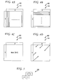
- the four Intra_16x16 modes 400 includes modes 0-3, with mode 0 ( FIG. 4A , indicated by reference numeral 410) corresponding to a vertical prediction mode, mode 1 ( FIG. 4B , indicated by reference numeral 411) corresponding to a horizontal prediction mode, mode 2 ( FIG. 4C , indicated by reference numeral 412) corresponding to a DC prediction mode, and mode 3 ( FIG. 4D , indicated by reference numeral 413) corresponding to a plane prediction mode.
- Intra8x8 is the same as that of Intra4x4.
- the prediction mode for luma coding in Intra16x16 mode or chroma coding in intra mode is signaled in the macroblock header and predictive coding of the mode is not used in these cases.
- the template matching intra prediction 170 involves a candidate neighborhood 172, a candidate patch 174, a template 176, and a target 178. Since the search region and the neighborhood (e.g., candidate neighborhood 172) of the current pixels (e.g., target 178) are known at the encoder and the decoder side, no additional side information has to be transmitted, and identical prediction is achieved on both sides.
- template matching on a 2x2 luma sample grid is applied to enable a joint prediction for luma and chroma samples in 4:2:0 video sequences.
- an apparatus includes an encoder for encoding picture data for at least a portion of a picture.
- the encoder derives an intra mode to apply to the portion from neighboring template data and abstains from explicitly signaling the intra mode for the portion.
- the neighboring template data corresponds to a neighboring template formed from neighboring pixels with respect to the portion.
- a method in a video decoder includes decoding picture data for at least a portion of a picture by deriving an intra mode to apply to the portion from neighboring template data in an absence of receiving any explicit signaling of the intra mode for the portion.
- the neighboring template data corresponds to a neighboring template formed from neighboring pixels with respect to the portion.
- any element expressed as a means for performing a specified function is intended to encompass any way of performing that function including, for example, a) a combination of circuit elements that performs that function or b) software in any form, including, therefore, firmware, microcode or the like, combined with appropriate circuitry for executing that software to perform the function.
- the present principles as defined by such claims reside in the fact that the functionalities provided by the various recited means are combined and brought together in the manner which the claims call for. It is thus regarded that any means that can provide those functionalities are equivalent to those shown herein.
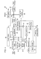
- an exemplary video encoder to which the present principles may be applied is indicated generally by the reference numeral 600.
- the method used to a signal an intra prediction mode is fundamental to the efficiency of current video encoders for intra coding.
- the prior art does not fully take advantage of neighboring data to determine the best prediction and prediction mode.
- the implicit signaling avoids the requirement of sending bits to convey what prediction mode should be used.
- the semi-implicit derivation aids in obtaining a better prediction (for example, with respect to rate-distortion) of the intra mode to use.
- the combination of implicit and explicit signaling combines the benefits of the previous approaches.
- the function block 1220 calculates a prediction and a sum of absolute difference (SAD) for the neighboring area of block i with mode j, and passes control to a loop limit block 1225.
- the loop limit block 1225 ends the loop j, and passes control to a function block 1230.
- the function block 1235 encodes a current block using mode_p, and passes control to a loop limit block 1240.
- the loop limit block 1240 ends the loop i, and passes control to an end block 1299.
- the loop limit block 1420 begins a loop j over each intra mode, from 1 to num_Intra_Modes, and passes control to a decision block 1425.
- the decision block 1425 determines whether or not j ⁇ ⁇ (mode_a). If so, then control is passed to a function block 1430. Otherwise, control is passed to a loop limit block 1435.
- the loop limit block 1535 ends the loop j, and passes control to a function block 1540.
- the function block 1545 decodes a current block using mode_p, and passes control to a loop limit block 1550.
- the loop limit block 1550 ends the loop i, and passes control to an end block 1599.
- FIGs. 16 and 17 illustrate how the implicit intra mode signaling is respectively included in a video encoder and decoder.
- mode_p ⁇ (mode_b, mode_neighbor_1, mode_neighbor_2, ..., mode_neighbor_n). This mode will be used to encode the current block. The same operation can be performed at the decoder and identical prediction mode is generated.
- the function block 1620 calculates a prediction and a sum of absolute difference (SAD) for the neighboring area of block i with mode j, and passes control to a loop limit block 1625.
- the loop limit block 1625 ends the loop j, and passes control to a function block 1630.
- the function block 1640 encodes the current block using mode_p, and passes control to a loop limit block 1645.
- the loop limit block 1645 ends the loop i, and passes control to an end block 1699.
- the method 1900 includes a start block 1905 that passes control to a loop limit block 1910.
- the loop limit block 1910 begins a loop i over each macroblock of a current picture (field or frame) or portion of a picture, from 0 to num_MBs_minus1, and passes control to a function block 1915.
- the function block 1930 calculates a prediction and a sum of absolute difference (SAD) for the neighboring area of block i with mode j, and passes control to the loop limit block 1935.
- SAD sum of absolute difference
- a high level syntax includes, but is not limited to, syntax at the slice header level, Supplemental Enhancement Information (SEI) level, Picture Parameter Set (PPS) level, Sequence Parameter Set (SPS) level and Network Abstraction Layer (NAL) unit header level.
- SEI Supplemental Enhancement Information
- PPS Picture Parameter Set
- SPS Sequence Parameter Set
- NAL Network Abstraction Layer
- one advantage/feature is an apparatus having an encoder for encoding picture data for at least a portion of a picture.
- the encoder derives an intra mode to apply to the portion from neighboring template data and abstains from explicitly signaling the intra mode for the portion.
- the neighboring template data corresponds to a neighboring template formed from neighboring pixels with respect to the portion.
Description
- The present principles relate generally to video encoding and decoding and, more particularly, to methods and apparatus for implicit and semi-implicit intra mode signaling for video encoders and decoders.
-
US 2008/304763 A1 relates to video coding and provides a method for determining a direction mode for an image block in intra prediction of video frames. A plurality of energy terms are calculated from a spatial frequency domain image block. Afterwards a determination of a coarse classification from these energy terms is provided. It is foreseen that the method provides a search for at least some of coarse classifications from among a subset of less than all possible direction modes. Moreover a search of a most likely direction mode determined from neighbour blocks may be provided. - The International Organization for Standardization/International Electrotechnical Commission (ISO/IEC) Moving Picture Experts Group-4 (MPEG-4)
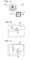
Part 10 Advanced Video Coding (AVC) standard/International Telecommunication Union, Telecommunication Sector (ITU-T) H.264 Recommendation (hereinafter the "MPEG-4 AVC Standard") is the first video coding standard that employs spatial directional prediction for intra coding. The MPEG-4 AVC Standard provides a more flexible prediction framework such that the coding efficiency is greatly improved over previous standards in which intra prediction was performed only in the transform domain. In the MPEG-4 AVC Standard, spatial intra prediction is performed using the surrounding available samples, which are the previously reconstructed samples available at the decoder within the same slice. For luma samples, intra prediction can be performed on a 4x4 block basis (denoted as Intra_4x4), an 8x8 block basis (denoted as Intra_8x8), and a 16x16 macroblock basis (denoted as Intra_16x16). Turning toFIG. 1A , MPEG-4 AVC Standard directional intra prediction with respect to a 4x4 block basis (Intra_4x4) is indicated generally by thereference numeral 100. Prediction directions are generally indicated by thereference numeral 110, image blocks are generally indicated by thereference numeral 120, and a current block is indicated by thereference numeral 130. In addition to luma prediction, a separate chroma prediction is conducted. There are a total of nine prediction modes for Intra_4x4 and Intra_8x8, four modes for Intra_16x16, and four modes for the chroma component. The encoder typically selects the prediction mode that minimizes the difference between the prediction and original block to be coded. A further intra coding mode, denoted I_PCM, allows the encoder to simply bypass the prediction and transform coding processes. The intra coding mode I_PCM allows the encoder to precisely represent the values of the samples and place an absolute limit on the number of bits that may be included in a coded macroblock without constraining decoded image quality. - Turning to
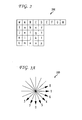
FIG. 2 , an exemplary labeling of prediction samples for Intra_4x4 in the MPEG-4 AVC Standard is indicated generally by thereference numeral 200. InFIG. 2 , the samples above and to the left of the current block (labeled with letters, from A to M) have been previously coded and reconstructed and, thus, they are available at the encoder and decoder to form the prediction. - Turning to
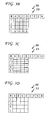
FIGs. 3B-J , Intra_4x4 luma prediction modes of the MPEG-4 AVC Standard are indicated generally by thereference numeral 300. The samples a, b, c, ..., p of the prediction block are calculated based on the samples A-M using the Intra_4x4luma prediction modes 300. The arrows inFIGs. 3B-J indicate the direction of prediction for each of theIntra_4x4 modes 300. TheIntra_4x4_luma prediction modes 300 include modes 0-8, with mode 0 (FIG. 3B , indicated by reference numeral 310) corresponding to a vertical prediction mode, mode 1 (FIG. 3C , indicated by reference numeral 311) corresponding to a horizontal prediction mode, mode 2 (FIG. 3D , indicated by reference numeral 312) corresponding to a DC mode, mode 3 (FIG. 3E , indicated by reference numeral 313) corresponding to a diagonal down-left mode, mode 4 (FIG. 3F , indicated by reference numeral 314) corresponding to a diagonal down-right mode, mode 5 (FIG. 3G , indicated by reference numeral 315) corresponding to a vertical-right mode, mode 6 (FIG. 3H , indicated by reference numeral 316) corresponding to a horizontal-down mode, mode 7 (FIG. 3I , indicated by reference numeral 317) corresponding to a vertical-left mode, and mode 8 (FIG. 3J , indicated by reference numeral 318) corresponding to a horizontal-up mode.FIG. 3A shows thegeneral prediction directions 330 corresponding to each of theIntra_4x4 modes 300. In modes 3-8 (corresponding toFIGs. 3E-J ), the predicted samples are formed from a weighted average of the prediction samples A-M. In DC mode corresponding toFIG. 3D , the predicted samples are the mean of the prediction samples A to D and I to L. Intra_8x8 uses basically the same concepts as the 4x4 predictions, but with a block size of 8x8 and with low-pass filtering of the predictors to improve prediction performance. - Turning to
FIGs. 4A-D , four Intra_16x16 modes corresponding to the MPEG-4 AVC Standard are indicated generally by thereference numeral 400. The four Intra_16x16modes 400 includes modes 0-3, with mode 0 (FIG. 4A , indicated by reference numeral 410) corresponding to a vertical prediction mode, mode 1 (FIG. 4B , indicated by reference numeral 411) corresponding to a horizontal prediction mode, mode 2 (FIG. 4C , indicated by reference numeral 412) corresponding to a DC prediction mode, and mode 3 (FIG. 4D , indicated by reference numeral 413) corresponding to a plane prediction mode. Each 8x8 chroma component of an intra coded macroblock is predicted from previously encoded chroma samples above and/or to the left. Both chroma components use the same prediction mode. The four prediction modes are very similar to the Intra_16x16, except that the numbering of the modes is different. The modes are DC (mode 0), horizontal (mode 1), vertical (mode 2) and plane (mode 3). - The choice of intra prediction mode for each 4x4 block must be signaled to the decoder and this could potentially require a large number of bits. The MPEG-4 AVC Standard has a particular method to signal the intra mode in order to avoid the use of a large number of bits. Intra modes for neighboring 4x4 blocks are often correlated. To take advantage of this correlation, predictive coding is used in the MPEG-4 AVC Standard to signal 4x4 intra modes. Turning to
FIG. 5 , exemplary block partitions to which the present principles may be applied are indicated generally by thereference numeral 500. The current block is designated by the reference character "E"). For each current block (e.g., block E inFIG. 5 ), the encoder and decoder calculate the most probable prediction mode, which is the minimum of the prediction modes of block A and block B. If either of these neighboring blocks is not available (outside the current slice or not coded in Intra4x4 mode), the corresponding mode value for the missing block (A or B) is set to 2 (DC prediction mode). - The encoder sends a flag for each 4x4 block, namely pre_intra4x4_pred_mode. If the flag is equal to 1, the most probable prediction mode is used. If the flag is equal to 0, another parameter rem_intra4x4_pred_mode is sent to indicate a change of mode. If rem_intra4x4_pred_mode is smaller than the current most probable mode, then the prediction mode is set to rem_intra4x4_pred_mode. Otherwise, the prediction mode is set to (rem_intra4x4_pred_mode+1). In this way, only eight values to transmit the chosen rem_intra4x4_pred_mode are used (0 to 7) to signal the current intra mode (0 to 8).
- The signaling of Intra8x8 is the same as that of Intra4x4. The prediction mode for luma coding in Intra16x16 mode or chroma coding in intra mode is signaled in the macroblock header and predictive coding of the mode is not used in these cases.
- Although the most probable mode is simple to compute and reduces the number of bits required for coding the prediction modes, it is not optimal in catching the local variations of block characteristics.
- During the development of the ITU-T H.26L Standard, displaced intra prediction was proposed. The proposal re-uses the concept of variable block size inter-prediction as specified in the MPEG-4 AVC Standard for intra prediction. Turning to
FIG. 1B , an example of displaced intra prediction is indicated generally by thereference numeral 150. The displacedintra prediction 150 involves an intracoded region 152, acurrent block 154, acandidate block 156, and adisplacement vector 158. In general, previously encoded intra regions (e.g., candidate block 156) of a slice can be referenced by displacement vectors (e.g., displacement vector 158) for prediction of the current intra block (e.g., current block 154). The displacedintra prediction 150 is implemented on a macroblock basis. The displacement vectors are encoded differentially using a prediction by the median of the neighboring blocks, in analogy to the inter motion vectors in the MPEG-4 AVC Standard. - Even though the preceding displaced intra prediction approach effectively improves coding efficiency when textures or patterns appear repeatedly in intra coded pictures, the preceding displaced intra prediction approach is limited by the fact that extra bits are required to transmit the value of the displacement vectors.
- Template matching prediction is a concept of texture synthesis to deal with the generation of a continuous texture that resembles a given sample. Template matching is for example known from T.K. Tan, C.S. Boon, and Y. Suzuki "Intra Prediction by Template Matching", ICIP 2006.
- Intra prediction using template matching in the context of the MPEG-4 AVC Standard has been proposed. In the proposal, the scheme is integrated as an additional mode for Intra4x4 or Intra8x8 prediction in the MPEG-4 AVC Standard. With template matching prediction, self-similarities of image regions are exploited for prediction. Previously encoded intra regions of a slice can be reused for prediction. The TMP algorithm recursively determines the value of current pixels under prediction by selecting at least one patch (of one or more pixels) of decoded data. Patches are selected according to a matching rule, where patch neighboring pixels are compared to current block neighboring pixels, and patches having the most similar neighboring pixels are selected. Turning to
FIG. 1C , an example of template matching intra prediction is indicated generally by thereference numeral 170. The template matchingintra prediction 170 involves acandidate neighborhood 172, acandidate patch 174, atemplate 176, and atarget 178. Since the search region and the neighborhood (e.g., candidate neighborhood 172) of the current pixels (e.g., target 178) are known at the encoder and the decoder side, no additional side information has to be transmitted, and identical prediction is achieved on both sides. Here, template matching on a 2x2 luma sample grid is applied to enable a joint prediction for luma and chroma samples in 4:2:0 video sequences. - Both displaced intra prediction (DIP) and template matching prediction (TMP) methods search the previously encoded regions in the current picture. However, DIP requires sending the displacement motion vectors while TM does not. TM does an implicit derivation of the displacement vector by means of comparing templates. The implicit derivation saves the bits of transmitting the displacement vectors.
- These and other drawbacks and disadvantages of the prior art are addressed by the present principles, which are directed to methods and apparatus for implicit and semi-implicit intra mode signaling for video encoders and decoders.
- According to an aspect of the present principles, there is provided an apparatus. The apparatus includes an encoder for encoding picture data for at least a portion of a picture. The encoder derives an intra mode to apply to the portion from neighboring template data and abstains from explicitly signaling the intra mode for the portion. The neighboring template data corresponds to a neighboring template formed from neighboring pixels with respect to the portion.
- According to yet another aspect of the present principles, there is provided a method in a video encoder. The method includes encoding picture data for at least a portion of a picture by deriving an intra mode to apply to the portion from neighboring template data, and abstaining from explicitly signaling the intra mode for the portion. The neighboring template data corresponds to a neighboring template formed from neighboring pixels with respect to the portion.
- According to still another aspect of the present principles, there is provided an apparatus. The apparatus includes a decoder for decoding picture data for at least a portion of a picture. The decoder derives an intra mode to apply to the portion from neighboring template data in an absence of receiving any explicit signaling of the intra mode for the portion. The neighboring template data corresponds to a neighboring template formed from neighboring pixels with respect to the portion.
- According to a further aspect of the present principles, there is provided a method in a video decoder. The method includes decoding picture data for at least a portion of a picture by deriving an intra mode to apply to the portion from neighboring template data in an absence of receiving any explicit signaling of the intra mode for the portion. The neighboring template data corresponds to a neighboring template formed from neighboring pixels with respect to the portion.
- These and other aspects, features and advantages of the present principles will become apparent from the following detailed description of exemplary embodiments, which is to be read in connection with the accompanying drawings.
- The present principles may be better understood in accordance with the following exemplary figures, in which:
-
FIG. 1A is a diagram showing MPEG-4 AVC Standard directional intra prediction with respect to a 4x4 block basis (Intra_4x4); -
FIG. 1B is a diagram showing an example of displaced intra prediction; -
FIG. 1C is a diagram showing an example of template matching intra prediction; -
FIG. 2 is a diagram showing labeling of prediction samples for the Intra_4x4 mode of the MPEG-4 AVC Standard; -
FIGs. 3A-J are diagrams showing Intra_4x4 luma prediction modes of the MPEG-4 AVC Standard; -
FIGs. 4A-D are diagrams respectively showing four Intra_16x16 modes corresponding to the MPEG-4 AVC Standard; -
FIG. 5 is a diagram showing exemplary block partitions to which the present principles may be applied; -
FIG. 6 is a block diagram showing an exemplary video encoder to which the present principles may be applied, in accordance with an embodiment of the present principles; -
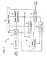
FIG. 7 is a block diagram showing an exemplary video decoder to which the present principles may be applied, in accordance with an embodiment of the present principles; -
FIG. 8 is a flow diagram showing an exemplary method for implicit intra mode signaling in a video encoder, in accordance with an embodiment of the present principles; -
FIG. 9 is a flow diagram showing an exemplary method for implicit intra mode signaling in a video decoder, in accordance with an embodiment of the present principles; -
FIG. 10 is a flow diagram showing an exemplary method for semi-implicit intra mode signaling in a video encoder, in accordance with an embodiment of the present principles; -
FIG. 11 is a flow diagram showing an exemplary method for semi-implicit intra mode signaling in a video decoder, in accordance with an embodiment of the present principles; -
FIG. 12 is a flow diagram showing an exemplary method for implicit intra mode signaling in a video encoder capable of supporting the MPEG-4 AVC Standard, in accordance with an embodiment of the present principles; -
FIG. 13 is a flow diagram showing an exemplary method for implicit intra mode signaling in a video decoder capable of supporting the MPEG-4 AVC Standard, in accordance with an embodiment of the present principles; -
FIG. 14 is a flow diagram showing an exemplary method for implicit intra mode signaling in a video encoder, in accordance with an embodiment of the present principles; -
FIG. 15 is a flow diagram showing an exemplary method for implicit intra mode signaling in a video decoder, in accordance with an embodiment of the present principles; -
FIG. 16 is a flow diagram showing an exemplary method for implicit intra mode signaling in a video encoder, in accordance with an embodiment of the present principles; -
FIG. 17 is a flow diagram showing an exemplary method for implicit intra mode signaling in a video decoder, in accordance with an embodiment of the present principles; -
FIG. 18 is a flow diagram showing an exemplary method for semi-implicit intra mode signaling in a video encoder, in accordance with an embodiment of the present principles; and -
FIG. 19 is a flow diagram showing an exemplary method for semi-implicit intra mode signaling in a video decoder, in accordance with an embodiment of the present principles. - The present principles are directed to methods and apparatus for implicit and semi-implicit intra mode signaling for video encoders and decoders.
- The present description illustrates the present principles. It will thus be appreciated that those skilled in the art will be able to devise various arrangements that, although not explicitly described or shown herein, embody the present principles and are included within its scope.
- All examples and conditional language recited herein are intended for pedagogical purposes to aid the reader in understanding the present principles and the concepts contributed by the inventor(s) to furthering the art, and are to be construed as being without limitation to such specifically recited examples and conditions.
- Moreover, all statements herein reciting principles, aspects, and embodiments of the present principles, as well as specific examples thereof, are intended to encompass both structural and functional equivalents thereof. Additionally, it is intended that such equivalents include both currently known equivalents as well as equivalents developed in the future, i.e., any elements developed that perform the same function, regardless of structure.
- Thus, for example, it will be appreciated by those skilled in the art that the block diagrams presented herein represent conceptual views of illustrative circuitry embodying the present principles. Similarly, it will be appreciated that any flow charts, flow diagrams, state transition diagrams, pseudocode, and the like represent various processes which may be substantially represented in computer readable media and so executed by a computer or processor, whether or not such computer or processor is explicitly shown.
- The functions of the various elements shown in the figures may be provided through the use of dedicated hardware as well as hardware capable of executing software in association with appropriate software. When provided by a processor, the functions may be provided by a single dedicated processor, by a single shared processor, or by a plurality of individual processors, some of which may be shared. Moreover, explicit use of the term "processor" or "controller" should not be construed to refer exclusively to hardware capable of executing software, and may implicitly include, without limitation, digital signal processor ("DSP") hardware, read-only memory ("ROM") for storing software, random access memory ("RAM"), and non-volatile storage.
- Other hardware, conventional and/or custom, may also be included. Similarly, any switches shown in the figures are conceptual only. Their function may be carried out through the operation of program logic, through dedicated logic, through the interaction of program control and dedicated logic, or even manually, the particular technique being selectable by the implementer as more specifically understood from the context.
- In the claims hereof, any element expressed as a means for performing a specified function is intended to encompass any way of performing that function including, for example, a) a combination of circuit elements that performs that function or b) software in any form, including, therefore, firmware, microcode or the like, combined with appropriate circuitry for executing that software to perform the function. The present principles as defined by such claims reside in the fact that the functionalities provided by the various recited means are combined and brought together in the manner which the claims call for. It is thus regarded that any means that can provide those functionalities are equivalent to those shown herein.
- Reference in the specification to "one embodiment" or "an embodiment" of the present principles, as well as other variations thereof, means that a particular feature, structure, characteristic, and so forth described in connection with the embodiment is included in at least one embodiment of the present principles. Thus, the appearances of the phrase "in one embodiment" or "in an embodiment", as well any other variations, appearing in various places throughout the specification are not necessarily all referring to the same embodiment.
- It is to be appreciated that the use of any of the following "/". "and/or", and "at least one of", for example, in the cases of "A/B", "A and/or B" and "at least one of A and B", is intended to encompass the selection of the first listed option (A) only, or the selection of the second listed option (B) only, or the selection of both options (A and B). As a further example, in the cases of "A, B, and/or C" and "at least one of A, B, and C", such phrasing is intended to encompass the selection of the first listed option (A) only, or the selection of the second listed option (B) only, or the selection of the third listed option (C) only, or the selection of the first and the second listed options (A and B) only, or the selection of the first and third listed options (A and C) only, or the selection of the second and third listed options (B and C) only, or the selection of all three options (A and B and C). This may be extended, as readily apparent by one of ordinary skill in this and related arts, for as many items listed.
- Moreover, it is to be appreciated that while one or more embodiments of the present principles are described herein with respect to the MPEG-4 AVC standard, the present principles are not limited to solely this standard and, thus, may be utilized with respect to other video coding standards, recommendations, and extensions thereof, including extensions of the MPEG-4 AVC standard, while maintaining the scope of the present principles.
- Moreover, as used herein, "high level syntax" refers to syntax present in the bitstream that resides hierarchically above the macroblock layer. For example, high level syntax, as used herein, may refer to, but is not limited to, syntax at the slice header level, Supplemental Enhancement Information (SEI) level, Picture Parameter Set (PPS) level, Sequence Parameter Set (SPS) level and Network Abstraction Layer (NAL) unit header level.
- Further, as used herein, "neighboring blocks" refers to blocks that are proximate to a current block in a particular picture.
- Also, as used herein, "neighboring template" refers to a region in a picture that is formed from, or that corresponds to, one or more neighboring pixels. Stated another way, "neighboring template" refers to e.g., an arrangement and/or selection of neighboring pixels, from which information (e.g., neighboring template data) for the current block may be derived.
- Additionally, as used herein, "neighboring template data" refers to data that is derived and/or otherwise obtained based on the neighboring template. For example, such data may be data relating to the one or more neighboring pixels that form a neighboring template. As a further example, such data may include, but is not limited to, intra mode information relating to one or more neighboring pixels that form a neighboring template.
- Turning to
FIG. 6 , an exemplary video encoder to which the present principles may be applied is indicated generally by thereference numeral 600. - The
video encoder 600 includes aframe ordering buffer 610 having an output in signal communication with a non-inverting input of acombiner 685. An output of thecombiner 685 is connected in signal communication with a first input of a transformer andquantizer 625. An output of the transformer andquantizer 625 is connected in signal communication with a first input of anentropy coder 645 and a first input of an inverse transformer andinverse quantizer 650. An output of theentropy coder 645 is connected in signal communication with a first non-inverting input of acombiner 690. An output of thecombiner 690 is connected in signal communication with a first input of anoutput buffer 635. - A first output of an
encoder controller 605 is connected in signal communication with a second input of theframe ordering buffer 610, a second input of the inverse transformer andinverse quantizer 650, an input of a picture-type decision module 615, a first input of a macroblock-type (MB-type)decision module 620, a second input of anintra prediction module 660, a second input of adeblocking filter 665, a first input of amotion compensator 670, a first input of amotion estimator 675, and a second input of areference picture buffer 680. - A second output of the
encoder controller 605 is connected in signal communication with a first input of a Supplemental Enhancement Information (SEI)inserter 630, a second input of the transformer andquantizer 625, a second input of theentropy coder 645, a second input of theoutput buffer 635, and an input of the Sequence Parameter Set (SPS) and Picture Parameter Set (PPS)inserter 640. - An output of the
SEI inserter 630 is connected in signal communication with a second non-inverting input of thecombiner 690. - A first output of the picture-
type decision module 615 is connected in signal communication with a third input of theframe ordering buffer 610. A second output of the picture-type decision module 615 is connected in signal communication with a second input of a macroblock-type decision module 620. - An output of the Sequence Parameter Set (SPS) and Picture Parameter Set (PPS)
inserter 640 is connected in signal communication with a third non-inverting input of thecombiner 690. - An output of the inverse quantizer and
inverse transformer 650 is connected in signal communication with a first non-inverting input of acombiner 619. An output of thecombiner 619 is connected in signal communication with a first input of theintra prediction module 660 and a first input of thedeblocking filter 665. An output of thedeblocking filter 665 is connected in signal communication with a first input of areference picture buffer 680. An output of thereference picture buffer 680 is connected in signal communication with a second input of themotion estimator 675 and a third input of themotion compensator 670. A first output of themotion estimator 675 is connected in signal communication with a second input of themotion compensator 670. A second output of themotion estimator 675 is connected in signal communication with a third input of theentropy coder 645. - An output of the
motion compensator 670 is connected in signal communication with a first input of aswitch 697. An output of theintra prediction module 660 is connected in signal communication with a second input of theswitch 697. An output of the macroblock-type decision module 620 is connected in signal communication with a third input of theswitch 697. The third input of theswitch 697 determines whether or not the "data" input of the switch (as compared to the control input, i.e., the third input) is to be provided by themotion compensator 670 or theintra prediction module 660. The output of theswitch 697 is connected in signal communication with a second non-inverting input of thecombiner 619 and an inverting input of thecombiner 685. - A first input of the
frame ordering buffer 610 and an input of theencoder controller 605 are available as inputs of theencoder 600, for receiving an input picture. Moreover, a second input of the Supplemental Enhancement Information (SEI)inserter 630 is available as an input of theencoder 600, for receiving metadata. An output of theoutput buffer 635 is available as an output of theencoder 500, for outputting a bitstream. - Turning to
FIG. 7 , an exemplary video decoder to which the present principles may be applied is indicated generally by thereference numeral 700. - The
video decoder 700 includes aninput buffer 710 having an output connected in signal communication with a first input of theentropy decoder 745. A first output of theentropy decoder 745 is connected in signal communication with a first input of an inverse transformer andinverse quantizer 750. An output of the inverse transformer andinverse quantizer 750 is connected in signal communication with a second non-inverting input of acombiner 725. An output of thecombiner 725 is connected in signal communication with a second input of adeblocking filter 765 and a first input of anintra prediction module 760. A second output of thedeblocking filter 765 is connected in signal communication with a first input of areference picture buffer 780. An output of thereference picture buffer 780 is connected in signal communication with a second input of amotion compensator 770. - A second output of the
entropy decoder 745 is connected in signal communication with a third input of themotion compensator 770 and a first input of thedeblocking filter 765. A third output of theentropy decoder 745 is connected in signal communication with an input of adecoder controller 705. A first output of thedecoder controller 705 is connected in signal communication with a second input of theentropy decoder 745. A second output of thedecoder controller 705 is connected in signal communication with a second input of the inverse transformer andinverse quantizer 750. A third output of thedecoder controller 705 is connected in signal communication with a third input of thedeblocking filter 765. A fourth output of thedecoder controller 705 is connected in signal communication with a second input of theintra prediction module 760, a first input of themotion compensator 670, and a second input of thereference picture buffer 780. - An output of the
motion compensator 770 is connected in signal communication with a first input of aswitch 797. An output of theintra prediction module 760 is connected in signal communication with a second input of theswitch 797. An output of theswitch 797 is connected in signal communication with a first non-inverting input of thecombiner 725. - An input of the
input buffer 710 is available as an input of thedecoder 700, for receiving an input bitstream. A first output of thedeblocking filter 765 is available as an output of thedecoder 700, for outputting an output picture. - As noted above, the present principles are directed to methods and apparatus for implicit and semi-implicit intra mode signaling for video encoders and decoders. In an embodiment, the present principles are based on template matching.
- Advantageously, the implicit intra mode derivation saves the transmission of bits to indicate the selected intra mode. In addition, we also describe a combination of explicit derivation with the implicit one. We call this mode a semi-implicit mode.
- Furthermore, as previously described, although the most probable mode as used by the prior art is simple to compute and reduces the number of bits required for coding the prediction modes, it is not optimal in catching the local variations of block characteristics. Thus, in accordance with the present principles, we take into account the local variations of block characteristics to provide an improved prediction of the most probable mode and, thus, reduce the required number of bits to signal the selected intra mode.
- The method used to a signal an intra prediction mode is fundamental to the efficiency of current video encoders for intra coding. The prior art does not fully take advantage of neighboring data to determine the best prediction and prediction mode. In accordance with the present principles, we propose new ways to derive the intra modes. In various embodiments, we described various methods for implicit and semi-implicit signaling, as well as combinations thereof. The implicit signaling avoids the requirement of sending bits to convey what prediction mode should be used. The semi-implicit derivation aids in obtaining a better prediction (for example, with respect to rate-distortion) of the intra mode to use. Also, the combination of implicit and explicit signaling combines the benefits of the previous approaches.
- Thus, in accordance with the preset principles, we propose the use of implicit and semi-implicit intra mode signaling. In an embodiment, the proposed scheme predicts the intra mode based on a template composed of neighboring samples. Given the mode of a region or block of a frame to be predicted, we test the neighboring template of the current block which is already decoded. The best mode for the neighboring patch will be predicted as the intra mode for the current block. We describe embodiments with an implicit signaling of the intra mode, as well as a semi-implicit derivation of the mode, and a combination of implicit and explicit modes. Although the background of the present principles is described in the context of the MPEG-4 AVC Standard, and the present principles are compared to the MPEG-4 AVC Standard in terms of benefits and advantages, the present principles apply in general to video encoding and decoding, and are not limited to (and, in fact, is non-compliant with) prior developed standards and recommendations.
- In an embodiment, the encoder can choose whether to send the mode prediction error, for example, using implicit or semi-implicit mode signaling. Since the neighborhood of the current pixel(s) are known at the encoder and the decoder side, no additional side information has to be transmitted, and identical prediction is achieved on both (encoder and decoder) sides.
- Turning to
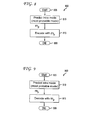
FIG. 8 , an exemplary method for implicit intra mode signaling in a video encoder is indicated generally by thereference numeral 800. Themethod 800 includes astart block 805 that passes control to afunction block 810. Thefunction block 810 predicts the intra mode as the most probable mode mp, and passes control to afunction block 815. Thefunction block 815 encodes a current block using the most probable mode mp, and passes control to anend block 899. - Turning to
FIG. 9 , an exemplary method for implicit intra mode signaling in a video decoder is indicated generally by thereference numeral 900. Themethod 900 includes astart block 905 that passes control to afunction block 910. Thefunction block 910 predicts the intra mode as the most probable mode mp, and passes control to afunction block 915. Thefunction block 915 decodes the current block using the most probable mode mp, and passes control to anend block 999. - Turning to
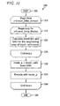
FIG. 10 , an exemplary method for semi-implicit intra mode signaling in a video encoder is indicated generally by thereference numeral 1000. Themethod 1000 includes astart block 1005 that passes control to afunction block 1010. Thefunction block 1010 predicts the intra mode as the most probable mode mL, and passes control to afunction block 1015 and adecision block 1020. Thefunction block 1015 derives the intra mode as the best rate-distortion based mode mRD (also referred to herein as "best_mode RD based"), and passes control to thedecision block 1020. Thedecision block 1020 determines whether or not mL = mRD. If so, then control is passed to afunction block 1025. Otherwise, control is passed to afunction block 1035. - The
function block 1025 sets the most_probable_mode = 1, and passes control to afunction block 1030. Thefunction block 1030 encodes the current block using mRD, and passes control to anend block 1099. - The
function block 1035 sets the most_probable_mode = 0, and passes control to afunction block 1040. Thefunction block 1040 signals intra prediction mode, and passes control to thefunction block 1030. - Turning to
FIG. 11 , an exemplary method for semi-implicit intra mode signaling in a video decoder is indicated generally by thereference numeral 1100. Themethod 1100 includes astart block 1105 that passes control to afunction block 1110. Thefunction block 1110 parses the bitstream, and passes control to afunction block 1115. Thefunction block 1115 predicts the intra mode for the current block as the most probable mode, and passes control to adecision block 1120. Thedecision block 1120 reads most_probable_mode and determines whether most_probable_mode is set to 1 or 0. If the most_probable_mode is set to 1, then control is passed to afunction block 1125. Otherwise, control is passed to afunction block 1135. - The
function block 1125 outputs the intra mode, and passes control to afunction block 1130. Thefunction block 1130 decodes the current block using MRD, and passes control to anend block 1199. - The
function block 1135 reads the intra prediction mode, and passes control to thefunction block 1125. - In a first illustrative embodiment relating to
FIGs. 12 and13 shown below, to decide the intra mode of the current block, we first search for the best intra mode of its neighboring patch. The encoder calculates the prediction for its neighboring patch with every one of the nine modes for Intra_4x4 and Intra_8x8, or four modes for Intra_16x16. Then, the encoder selects the mode that minimizes the difference (SAD, MSE, and/or so forth) between the prediction and the decoded neighboring patch. This mode mode_p will be used to encode the current block. The same operation can be performed at the decoder and the identical prediction mode is generated. - Turning to
FIG. 12 , an exemplary method for implicit intra mode signaling in a video encoder capable of supporting the MPEG-4 AVC Standard is indicated generally by thereference numeral 1200. Themethod 1200 includes astart block 1205 that passes control to aloop limit block 1210. Theloop limit block 1210 begins a loop i over each macroblock of a current picture (field or frame) or portion of a picture, from 0 to num_MBs_minus1, and passes control to aloop limit block 1215. Theloop limit block 1215 begins a loop j over each intra mode, from 1 to num_Intra_Modes, and passes control to afunction block 1220. Thefunction block 1220 calculates a prediction and a sum of absolute difference (SAD) for the neighboring area of block i with mode j, and passes control to aloop limit block 1225. Theloop limit block 1225 ends the loop j, and passes control to afunction block 1230. Thefunction block 1230 sets mode_p = mode j with the least SAD, and passes control to afunction block 1235. Thefunction block 1235 encodes a current block using mode_p, and passes control to aloop limit block 1240. Theloop limit block 1240 ends the loop i, and passes control to anend block 1299. - Turning to
FIG. 13 , an exemplary method for implicit intra mode signaling in a video decoder capable of supporting the MPEG-4 AVC Standard is indicated generally by thereference numeral 1300. Themethod 1300 includes astart block 1305 that passes control to aloop limit block 1310. Theloop limit block 1310 begins a loop i over each macroblock of a current picture (field or frame) or portion of a picture, from 0 to num_MBs_minus1, and passes control to aloop limit block 1315. Theloop limit block 1315 begins a loop j over each intra mode, from 1 to num_Intra_Modes, and passes control to afunction block 1320. Thefunction block 1320 calculates a prediction and a sum of absolute difference (SAD) for the neighboring area of block i with mode j, and passes control to aloop limit block 1325. Theloop limit block 1325 ends the loop j, and passes control to afunction block 1330. Thefunction block 1330 sets mode_p = mode j with the least SAD, and passes control to afunction block 1335. Thefunction block 1335 decodes a current block using mode_p, and passes control to aloop limit block 1340. Theloop limit block 1340 ends the loop i, and passes control to anend block 1399. - In a second illustrative embodiment relating to
FIGs. 14 and15 shown below, we consider the MPEG-4 AVC Standard most probable mode and reduce the computational complexity by only searching within a limited range.FIGs. 14 and15 illustrate how the implicit intra mode signaling is respectively included in a video encoder and decoder. Before encoding the current block, we set the most probable mode as follows: - mode_a = f (mode_neighbor_1, mode_neighbor_2, ..., mode_neighbor_n),
- Turning to
FIG. 14 , an exemplary method for implicit intra mode signaling in a video encoder is indicated generally by thereference numeral 1400. Themethod 1400 includes astart block 1405 that passes control to aloop limit block 1410. Theloop limit block 1410 begins a loop i over each macroblock of a current picture (field or frame) or portion of a picture, from 0 to num_MBs_minus1, and passes control to afunction block 1415. Thefunction block 1415 sets mode_a = f(mode_neighbor_1, mode_neighbor_2, ..., mode_neighbor_n), and passes control to aloop limit block 1420. Theloop limit block 1420 begins a loop j over each intra mode, from 1 to num_Intra_Modes, and passes control to adecision block 1425. Thedecision block 1425 determines whether or not j ∈ ϕ(mode_a). If so, then control is passed to afunction block 1430. Otherwise, control is passed to aloop limit block 1435. - The
function block 1430 calculates a prediction and a sum of absolute difference (SAD) for the neighboring area of block i with mode j, and passes control to theloop limit block 1435. - The
loop limit block 1435 ends the loop j, and passes control to afunction block 1440. Thefunction block 1440 sets mode_p = mode j with the least SAD, and passes control to afunction block 1445. Thefunction block 1445 encodes a current block using mode_p, and passes control to aloop limit block 1450. Theloop limit block 1450 ends the loop i, and passes control to anend block 1499. - Turning to
FIG. 15 , an exemplary method for implicit intra mode signaling in a video decoder is indicated generally by thereference numeral 1500. Themethod 1500 includes astart block 1505 that passes control to aloop limit block 1510. Theloop limit block 1510 begins a loop i over each macroblock of a current picture (field or frame) or portion of a picture, from 0 to num_MBs_minus1, and passes control to afunction block 1515. Thefunction block 1515 sets mode_a = f(mode_neighbor_1, mode_neighbor_2, ..., mode_neighbor_n), and passes control to aloop limit block 1520. Theloop limit block 1520 begins a loop j over each intra mode, from 1 to num_Intra_Modes, and passes control to adecision block 1525. Thedecision block 1525 determines whether or not j ∈ ϕ(mode_a). If so, then control is passed to afunction block 1530. Otherwise, control is passed to aloop limit block 1535. - The
function block 1530 calculates a prediction and a sum of absolute difference (SAD) for the neighboring area of block i with mode j, and passes control to theloop limit block 1535. - The
loop limit block 1535 ends the loop j, and passes control to afunction block 1540. Thefunction block 1540 sets mode_p = mode j with the least SAD, and passes control to afunction block 1545. Thefunction block 1545 decodes a current block using mode_p, and passes control to aloop limit block 1550. Theloop limit block 1550 ends the loop i, and passes control to anend block 1599. - In a third illustrative embodiment relating to
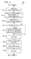
FIGs. 16 and17 shown below, we use the MPEG-4 AVC Standard most probable mode to reduce intra prediction residues and improve the coding efficiency.FIGs. 16 and17 illustrate how the implicit intra mode signaling is respectively included in a video encoder and decoder. After the encoder selects the best intra mode mode_b for the neighboring patch, we predict the intra mode of the current block as mode_p = ϕ(mode_b, mode_neighbor_1, mode_neighbor_2, ..., mode_neighbor_n). This mode will be used to encode the current block. The same operation can be performed at the decoder and identical prediction mode is generated. - Turning to
FIG. 16 , an exemplary method for implicit intra mode signaling in a video encoder is indicated generally by thereference numeral 1600. Themethod 1600 includes astart block 1605 that passes control to aloop limit block 1610. Theloop limit block 1610 begins a loop i over each macroblock of a current picture (field or frame) or portion of a picture, from 0 to num_MBs_minus1, and passes control to aloop limit block 1615. Theloop limit block 1615 begins a loop j over each intra mode, from 1 to num_Intra_Modes, and passes control to afunction block 1620. Thefunction block 1620 calculates a prediction and a sum of absolute difference (SAD) for the neighboring area of block i with mode j, and passes control to aloop limit block 1625. Theloop limit block 1625 ends the loop j, and passes control to afunction block 1630. Thefunction block 1630 sets mode_b = mode j with least SAD, and passes control to afunction block 1635. Thefunction block 1635 sets mode predictor mode_p = ϕ(mode_b_, mode_neighboring_1, ..., mode_neighbor_n), and passes control to afunction block 1640. Thefunction block 1640 encodes the current block using mode_p, and passes control to aloop limit block 1645. Theloop limit block 1645 ends the loop i, and passes control to anend block 1699. - Turning to
FIG. 17 , an exemplary method for implicit intra mode signaling in a video decoder is indicated generally by thereference numeral 1700. Themethod 1700 includes astart block 1705 that passes control to aloop limit block 1710. Theloop limit block 1710 begins a loop i over each macroblock of a current picture (field or frame) or portion of a picture, from 0 to num_MBs_minus1, and passes control to aloop limit block 1715. Theloop limit block 1715 begins a loop j over each intra mode, from 1 to num_Intra_Modes, and passes control to afunction bock 1720. Thefunction block 1720 calculates a prediction and a sum of absolute difference (SAD) for the neighboring area of block i with mode j, and passes control to aloop limit block 1725. Theloop limit block 1725 ends the loop j, and passes control to afunction block 1730. Thefunction block 1730 sets mode_b = mode j with least SAD, and passes control to afunction block 1735. Thefunction block 1735 sets mode predictor mode_p = ϕ(mode_b_, mode_neighboring_1 mode_neighbor_n), and passes control to afunction block 1740. Thefunction block 1740 decodes the current block using mode_p, and passes control to aloop limit block 1745. Theloop limit block 1745 ends the loop i, and passes control to anend block 1799. - In a fourth illustrative embodiment relating to
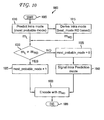
FIGs. 18 and19 shown below, the encoder can send the mode prediction error to the decoder.FIGs. 18 and19 illustrate how the semi-implicit intra mode signaling is respectively included in a video encoder and decoder. Before encoding the current block, we set the most probable mode as mode_a = f (mode_neighbor_1, mode_neighbor_2, ..., mode_neighbor_n), where mode_neighbor_i is the intra mode of a neighboring block and f(.) is a function of the neighboring blocks modes. As a particular embodiment, we can set mode_a = min(mode_up, mode_left), similarly as the MPEG-4 AVC Standard most probable mode. To decide the intra mode of the current block, we test its neighboring patch only with the set of modes that are correlated with mode_a. Predictions and SADs are calculated for each mode in the set M = ψ(mode_a) before the best mode mode_b is selected from M. In particular, if we order the intra modes as in the MPEG-4 AVC Standard, we can set ψ(mode_a) to the region [max{0, mode_a - 2}, min{mode_a + 1, mode_max}] where mode_max is the maximum mode index. Then, the intra mode of the current block is predicted as mode_p = ϕ(mode_b, mode_neighbor_1, mode_neighbor_2, ..., mode_neighbor_n). One possible embodiment of this function ϕ is mode_p = median{mode_b, mode_up, mode_left}. After that, rate-distortion (RD) optimized mode decision is performed for the current block. The best mode mode_rd is the one that provides the minimum RD cost, which takes into consideration the rate required for coding a mode with respect to mode_p. Finally, the difference between mode_rd and mode_p is signaled to the decoder as in the MPEG-4 AVC Standard, and the same operation can be performed at the decoder to generate identical prediction. - Turning to
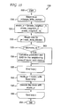
FIG. 18 , an exemplary method for semi-implicit intra mode signaling in a video encoder is indicated generally by thereference numeral 1800. Themethod 1800 includes astart block 1805 that passes control to aloop limit block 1810. Theloop limit block 1810 begins a loop i over each macroblock of a current picture (field or frame) or portion of a picture, from 0 to num_MBs_minus1, and passes control to afunction block 1815. Thefunction block 1815 sets mode_a = f(mode_neighbor_1, mode_neighbor_2, ..., mode_neighbor_n), and passes control to aloop limit block 1820. Theloop limit block 1820 begins a loop j over each intra mode, from 1 to num_Intra_Modes, and passes control to adecision block 1825. Thedecision block 1825 determines whether or not j ∈ ϕ(mode_a). If so, then control is passed to afunction block 1830. Otherwise, control is passed to aloop limit block 1835. - The
function block 1830 calculates a prediction and a sum of absolute difference (SAD) for the neighboring area of block i with mode j, and passes control to theloop limit block 1835. - The
loop limit block 1835 ends the loop j, and passes control to afunction block 1840. Thefunction block 1840 sets mode_b = mode j with the least SAD, and passes control to afunction block 1845. Thefunction block 1845 sets mode predictor mode_p = ϕ(mode_b_, mode_neighboring_1, ..., mode_neighbor_n), and passes control to afunction block 1850. Thefunction block 1850 performs a mode decision for the current block as mode_rd, and passes control to afunction block 1855. Thefunction block 1855 entropy encodes mode_rd with respect to mode_p, and passes control to aloop limit block 1860. Theloop limit block 1860 ends the loop i, and passes control to anend block 1899. - Turning to
FIG. 19 , an exemplary method for semi-implicit intra mode signaling in a video decoder is indicated generally by thereference numeral 1900. Themethod 1900 includes astart block 1905 that passes control to aloop limit block 1910. Theloop limit block 1910 begins a loop i over each macroblock of a current picture (field or frame) or portion of a picture, from 0 to num_MBs_minus1, and passes control to afunction block 1915. Thefunction block 1915 sets mode_a = f(mode_neighbor_1, mode_neighbor_2, ..., mode_neighbor_n), and passes control to aloop limit block 1920. Theloop limit block 1920 begins a loop j over each intra mode, from 1 to num_Intra_Modes, and passes control to adecision block 1925. Thedecision block 1925 determines whether or not j ∈ ϕ(mode_a). If so, then control is passed to afunction block 1930. Otherwise, control is passed to aloop limit block 1935. - The
function block 1930 calculates a prediction and a sum of absolute difference (SAD) for the neighboring area of block i with mode j, and passes control to theloop limit block 1935. - The
loop limit block 1935 ends the loop j, and passes control to afunction block 1940. Thefunction block 1940 sets mode_b = mode j with the least SAD, and passes control to afunction block 1945. Thefunction block 1945 sets mode predictor mode_p = ϕ(mode_b_, mode_neighboring_1, ..., mode_neighbor_n), and passes control to afunction block 1950. Thefunction block 1950 decodes mode_rd based on mode_p, and passes control to afunction block 1955. Thefunction block 1955 decodes the current block using mode_rd, and passes control to aloop limit block 1960. Theloop limit block 1960 ends the loop i, and passes control to anend block 1999. - In a fifth embodiment, we use the implicit modes for some of the blocks and the explicit modes for the other blocks. This implicit-explicit combination of modes provides the best choice in the rate-distortion (RD) sense for all the explicit blocks, which are satisfactory anchors for the implicit blocks. Meanwhile, side information does not have to be sent for "implicit blocks", as is done for "explicit blocks", however the "implicit blocks" use the "explicit blocks" as a good reference(s) to derive the most probable mode. Using this combination of blocks, the benefits of implicit and explicit signaling can be obtained.
- The enabling or disabling of the present principles can be signaled in high level syntax. As noted above, a high level syntax includes, but is not limited to, syntax at the slice header level, Supplemental Enhancement Information (SEI) level, Picture Parameter Set (PPS) level, Sequence Parameter Set (SPS) level and Network Abstraction Layer (NAL) unit header level.
- A description will now be given of some of the many attendant advantages/features of the present invention, some of which have been mentioned above. For example, one advantage/feature is an apparatus having an encoder for encoding picture data for at least a portion of a picture. The encoder derives an intra mode to apply to the portion from neighboring template data and abstains from explicitly signaling the intra mode for the portion. The neighboring template data corresponds to a neighboring template formed from neighboring pixels with respect to the portion.
- Another advantage/feature is the apparatus having the encoder as described above, wherein the intra mode for the portion is implicitly derived using the neighboring template data to test a subset of a set of available intra modes, and a particular intra mode within the subset is selected as the intra mode for the portion based upon a least distortion measure.
- Yet another advantage/feature is the apparatus having the encoder wherein the intra mode for the portion is implicitly derived using the neighboring template data to test a subset of a set of available intra modes, and a particular intra mode within the subset is selected as the intra mode for the portion based upon a least distortion measure as described above, wherein the least distortion measure is determined based upon a sum of absolute difference or a mean square error.
- Still another advantage/feature is the apparatus having the encoder wherein the intra mode for the portion is implicitly derived using the neighboring template data to test a subset of a set of available intra modes, and a particular intra mode within the subset is selected as the intra mode for the portion based upon a least distortion measure as described above, wherein the subset is determined based upon a function of intra modes used for neighboring blocks.
- Moreover, another advantage/feature is the apparatus having the encoder wherein the intra mode for the portion is implicitly derived using the neighboring template data to test a subset of a set of available intra modes, and a particular intra mode within the subset is selected as the intra mode for the portion based upon a least distortion measure as described above, wherein the intra mode for the portion is further implicitly derived as a function of intra modes for the neighboring blocks and a best mode for the neighboring template.
- Further, another advantage/feature is the apparatus having the encoder wherein the intra mode for the portion is further implicitly derived as a function of intra modes for the neighboring blocks and a best mode for the neighboring template as described above, wherein the best mode for the neighboring template is determined by testing several or all intra modes used for the neighboring template, and selecting a given intra mode that provides a least distortion measure, from among the several or all intra modes used for the neighboring template, as the best mode for the neighboring template.
- Also, another advantage/feature is the apparatus having the encoder wherein the intra mode for the portion is further implicitly derived as a function of intra modes for the neighboring blocks and a best mode for the neighboring template as described above, wherein the function is a median function.
- Additionally, another advantage/feature is the apparatus having the encoder as described above, wherein an implicit intra mode derivation is performed for a subset of blocks in a picture, while an explicit intra mode signaling is performed for the other blocks in the picture, the subset of blocks being the portion.
- These and other features and advantages of the present principles may be readily ascertained by one of ordinary skill in the pertinent art based on the teachings herein. It is to be understood that the teachings of the present principles may be implemented in various forms of hardware, software, firmware, special purpose processors, or combinations thereof.
- Most preferably, the teachings of the present principles are implemented as a combination of hardware and software. Moreover, the software may be implemented as an application program tangibly embodied on a program storage unit. The application program may be uploaded to, and executed by, a machine comprising any suitable architecture. Preferably, the machine is implemented on a computer platform having hardware such as one or more central processing units ("CPU"), a random access memory ("RAM"), and input/output ("I/O") interfaces. The computer platform may also include an operating system and microinstruction code. The various processes and functions described herein may be either part of the microinstruction code or part of the application program, or any combination thereof, which may be executed by a CPU. In addition, various other peripheral units may be connected to the computer platform such as an additional data storage unit and a printing unit.
- It is to be further understood that, because some of the constituent system components and methods depicted in the accompanying drawings are preferably implemented in software, the actual connections between the system components or the process function blocks may differ depending upon the manner in which the present principles are programmed. Given the teachings herein, one of ordinary skill in the pertinent art will be able to contemplate these and similar implementations or configurations of the present principles.
- Although the illustrative embodiments have been described herein with reference to the accompanying drawings, it is to be understood that the present principles is not limited to those precise embodiments, and that various changes and modifications may be effected therein by one of ordinary skill in the pertinent art without departing from the scope of the present principles. All such changes and modifications are intended to be included within the scope of the present principles as set forth in the appended claims.
Claims (10)
- An apparatus having an encoder (600) for encoding picture data for at least a portion of a picture, comprising:wherein said encoder derives an intra mode to apply to the portion from neighboring template data and abstains from explicitly signaling the intra mode for the portion, the neighboring template data corresponding to a neighboring template formed from previously encoded neighboring pixels with respect to the portion, andcharacterized in thatthe intra mode for the portion is implicitly derived using the neighboring template data to test a subset of a set of available intra modes, and a particular intra mode within the subset is selected as the intra mode for the portion based upon a least distortion measure from among respective distortion measures between predicted values and decoded values obtained using the intra modes in the subset, the predicted values and the decoded values corresponding to a candidate neighboring patch within a candidate neighborhood with respect to the portion.
- The apparatus of claim 1, wherein an implicit intra mode derivation is performed for a subset of blocks in a picture, while an explicit intra mode signaling is performed for the other blocks in the picture, the subset of blocks being the portion.
- In a video encoder, a method for encoding picture data for at least a portion of a picture, comprising:deriving an intra mode to apply to the portion from neighboring template data (1220, 1230, 1415, 1425, 1430, 1440, 1620, 1630, 1635); andabstaining from explicitly signaling the intra mode for the portion, wherein the neighboring template data corresponds to a neighboring template formed from previously encoded neighboring pixels with respect to the portion, and characterized in thatthe intra mode for the portion is implicitly derived using the neighboring template data to test a subset of a set of available intra modes, and a particular intra mode within the subset is selected as the intra mode for the portion based upon a least distortion measure from among respective distortion measures between predicted values and decoded values obtained using the intra modes in the subset, the predicted values and the decoded values corresponding to a candidate neighboring patch within a candidate neighborhood with respect to the portion.
- The method of claim 3, wherein an implicit intra mode derivation is performed for a subset of blocks in a picture, while an explicit intra mode signaling is performed for the other blocks in the picture (1815, 1825, 1830, 1840, 1845, 1855), the subset of blocks being the portion.
- An apparatus having a decoder (700) for decoding picture data for at least a portion of a picture, comprising:wherein said decoder derives an intra mode to apply to the portion from neighboring template data in an absence of receiving any explicit signaling of the intra mode for the portion, the neighboring template data corresponding to a neighboring template formed from previously decoded neighboring pixels with respect to the portion, and characterized in thatthe intra mode for the portion is implicitly derived using the neighboring template data to test a subset of a set of available intra modes, and a particular intra mode within the subset is selected as the intra mode for the portion based upon a least distortion measure from among respective distortion measures between predicted values and decoded values obtained using the intra modes in the subset, the predicted values and the decoded values corresponding to a candidate neighboring patch within a candidate neighborhood with respect to the portion.
- The apparatus of claim 5, wherein an implicit intra mode derivation is performed for a subset of blocks in a picture, while an explicit intra mode derivation is performed for the other blocks in the picture, the subset of blocks being the portion.
- In a video decoder, a method for decoding picture data for at least a portion of a picture, comprising:decoding picture data for at least a portion of a picture by deriving an intra mode to apply to the portion from neighboring template data in an absence of receiving any explicit signaling of the intra mode for the portion,wherein the neighboring template data corresponds to a neighboring template formed from previously decoded neighboring pixels with respect to the portion (1320, 1330, 1515, 1525, 1530, 1540, 1720, 1730, 1735) and characterized in thatthe intra mode for the portion is implicitly derived using the neighboring template data to test a subset of a set of available intra modes, and a particular intra mode within the subset is selected as the intra mode for the portion based upon a least distortion measure from among respective distortion measures between predicted values and decoded values obtained using the intra modes in the subset, the predicted values and the decoded values corresponding to a candidate neighboring patch within a candidate neighborhood with respect to the portion.
- The apparatus of claim 1 or 5 or method of claim 3 or 7, wherein the least distortion measure is determined based upon a sum of absolute difference or a mean square error.
- The method of claim 7, wherein an implicit intra mode derivation is performed for a subset of blocks in a picture, while an explicit intra mode derivation is performed for the other blocks in the picture, the subset of blocks being the portion (1915, 1925, 1930, 1940, 1945, 1950, 1955).
- A computer readable storage media having video signal data encoded thereupon, the video signal data comprising encoded picture data for at least a portion of a picture, wherein the picture data is encoded by deriving an intra mode to apply to the portion from neighboring template data,
wherein the neighboring template data corresponds to a neighboring template formed from neighboring previously encoded pixels with respect to the portion, and the encoded picture data is arranged to enable a determination of the intra mode for the portion by a corresponding decoder without any explicit signaling of the intra mode for the portion to the decoder and characterized in that
the intra mode for the portion is implicitly derived using the neighboring template data to test a subset of a set of available intra modes, and a particular intra mode within the subset is selected as the intra mode for the portion based upon a least distortion measure from among respective distortion measures between predicted values and decoded values obtained using the intra modes in the subset, the predicted values and the decoded values corresponding to a candidate neighboring patch within a candidate neighborhood with respect to the portion.
Applications Claiming Priority (2)
| Application Number | Priority Date | Filing Date | Title |
|---|---|---|---|
| US15043109P | 2009-02-06 | 2009-02-06 | |
| PCT/US2010/000321 WO2010090749A1 (en) | 2009-02-06 | 2010-02-05 | Methods and apparatus for implicit and semi-implicit intra mode signaling for video encoders and decoders |
Publications (2)
| Publication Number | Publication Date |
|---|---|
| EP2394437A1 EP2394437A1 (en) | 2011-12-14 |
| EP2394437B1 true EP2394437B1 (en) | 2015-04-08 |
Family
ID=42035841
Family Applications (1)
| Application Number | Title | Priority Date | Filing Date |
|---|---|---|---|
| EP10704433.1A Not-in-force EP2394437B1 (en) | 2009-02-06 | 2010-02-05 | Methods and apparatus for implicit and semi-implicit intra mode signaling for video encoders and decoders |
Country Status (7)
| Country | Link |
|---|---|
| US (1) | US9288494B2 (en) |
| EP (1) | EP2394437B1 (en) |
| JP (1) | JP5564061B2 (en) |
| KR (1) | KR101665547B1 (en) |
| CN (1) | CN102308586B (en) |
| BR (1) | BRPI1008081A2 (en) |
| WO (1) | WO2010090749A1 (en) |
Cited By (1)
| Publication number | Priority date | Publication date | Assignee | Title |
|---|---|---|---|---|
| US11722677B2 (en) * | 2016-05-06 | 2023-08-08 | Interdigital Madison Patent Holdings, Sas | Method and system for decoder-side intra mode derivation for block-based video coding |
Families Citing this family (37)
| Publication number | Priority date | Publication date | Assignee | Title |
|---|---|---|---|---|
| EP3579558A1 (en) | 2009-07-01 | 2019-12-11 | InterDigital VC Holdings, Inc. | Methods and apparatus for signaling intra prediction for large blocks for video encoders and decoders |
| EP3057323B1 (en) * | 2010-11-26 | 2018-07-04 | NEC Corporation | Video decoding device, video decoding method, and program |
| KR101756442B1 (en) * | 2010-11-29 | 2017-07-11 | 에스케이텔레콤 주식회사 | Video Encoding/Decoding Method and Apparatus for Minimizing Redundancy of Intra Prediction Mode |
| KR20120070479A (en) | 2010-12-21 | 2012-06-29 | 한국전자통신연구원 | Method and apparatus for encoding and decoding of intra prediction mode information |
| MX2013006339A (en) * | 2011-01-07 | 2013-08-26 | Mediatek Singapore Pte Ltd | Method and apparatus of improved intra luma prediction mode coding. |
| JP5781313B2 (en) | 2011-01-12 | 2015-09-16 | 株式会社Nttドコモ | Image prediction coding method, image prediction coding device, image prediction coding program, image prediction decoding method, image prediction decoding device, and image prediction decoding program |
| ES2604202T3 (en) * | 2011-03-10 | 2017-03-03 | Nippon Telegraph And Telephone Corporation | Quantification control device and procedure, and quantification control program |
| CN102685474B (en) * | 2011-03-10 | 2014-11-05 | 华为技术有限公司 | Encoding and decoding method of prediction modes, encoding and decoding device and network system |
| GB2491391B (en) * | 2011-06-02 | 2014-09-03 | Canon Kk | Encoding mode values representing prediction modes |
| US9654785B2 (en) * | 2011-06-09 | 2017-05-16 | Qualcomm Incorporated | Enhanced intra-prediction mode signaling for video coding using neighboring mode |
| TR201906149T4 (en) | 2011-06-28 | 2019-05-21 | Samsung Electronics Co Ltd | Method and apparatus for encoding video with internal prediction. |
| GB2494468B (en) * | 2011-09-12 | 2014-01-15 | Canon Kk | Method and device for encoding or decoding information representing prediction modes |
| WO2013062193A1 (en) | 2011-10-24 | 2013-05-02 | (주)인터앱 | Method and apparatus for image decoding |
| US9154796B2 (en) * | 2011-11-04 | 2015-10-06 | Qualcomm Incorporated | Intra-mode video coding |
| CN104247432B (en) | 2011-11-11 | 2019-06-11 | Ge视频压缩有限责任公司 | The efficient multi-vision-point encoding estimated using depth map and updated |
| WO2013068548A2 (en) | 2011-11-11 | 2013-05-16 | Fraunhofer-Gesellschaft zur Förderung der angewandten Forschung e.V. | Efficient multi-view coding using depth-map estimate for a dependent view |
| US9628789B2 (en) | 2011-11-18 | 2017-04-18 | Qualcomm Incorporated | Reference mode selection in intra mode coding |
| EP2781091B1 (en) | 2011-11-18 | 2020-04-08 | GE Video Compression, LLC | Multi-view coding with efficient residual handling |
| US9210438B2 (en) * | 2012-01-20 | 2015-12-08 | Sony Corporation | Logical intra mode naming in HEVC video coding |
| EP2829065B1 (en) * | 2012-03-21 | 2020-05-13 | MediaTek Singapore Pte Ltd. | Method and apparatus for intra mode derivation and coding in scalable video coding |
| WO2014053514A1 (en) | 2012-10-01 | 2014-04-10 | Fraunhofer-Gesellschaft zur Förderung der angewandten Forschung e.V. | Scalable video coding using base-layer hints for enhancement layer motion parameters |
| US9674543B2 (en) | 2012-11-14 | 2017-06-06 | Samsung Electronics Co., Ltd. | Method for selecting a matching block |
| WO2014190468A1 (en) | 2013-05-27 | 2014-12-04 | Microsoft Corporation | Video encoder for images |
| EP3120556B1 (en) | 2014-03-17 | 2021-01-13 | Microsoft Technology Licensing, LLC | Encoder-side decisions for screen content encoding |
| JP2017537529A (en) * | 2014-10-31 | 2017-12-14 | サムスン エレクトロニクス カンパニー リミテッド | Video encoding apparatus and video decoding apparatus using high-precision skip encoding, and method thereof |
| EP3254463A4 (en) | 2015-02-06 | 2018-02-21 | Microsoft Technology Licensing, LLC | Skipping evaluation stages during media encoding |
| US10038917B2 (en) * | 2015-06-12 | 2018-07-31 | Microsoft Technology Licensing, Llc | Search strategies for intra-picture prediction modes |
| US10136132B2 (en) | 2015-07-21 | 2018-11-20 | Microsoft Technology Licensing, Llc | Adaptive skip or zero block detection combined with transform size decision |
| US20180249156A1 (en) * | 2015-09-10 | 2018-08-30 | Lg Electronics Inc. | Method for processing image based on joint inter-intra prediction mode and apparatus therefor |
| US10390021B2 (en) * | 2016-03-18 | 2019-08-20 | Mediatek Inc. | Method and apparatus of video coding |
| CA3024900C (en) | 2016-05-17 | 2021-02-16 | Arris Enterprises Llc | Template matching for jvet intra prediction |
| US10397569B2 (en) | 2016-06-03 | 2019-08-27 | Mediatek Inc. | Method and apparatus for template-based intra prediction in image and video coding |
| EP3451665A1 (en) * | 2017-09-01 | 2019-03-06 | Thomson Licensing | Refinement of internal sub-blocks of a coding unit |
| EP3771212A4 (en) * | 2018-04-11 | 2021-05-12 | Sony Corporation | Image processing device and method |
| US10999604B2 (en) * | 2018-04-13 | 2021-05-04 | Mediatek Inc. | Adaptive implicit transform setting |
| US11197001B2 (en) * | 2020-02-05 | 2021-12-07 | Tencent America LLC | Method and apparatus for interactions between decoder-side intra mode derivation and adaptive intra prediction modes |
| WO2023219289A1 (en) * | 2022-05-12 | 2023-11-16 | 현대자동차주식회사 | Method for deriving intra-prediction mode on basis of reference pixel |
Family Cites Families (27)
| Publication number | Priority date | Publication date | Assignee | Title |
|---|---|---|---|---|
| CN1183769C (en) | 1996-05-28 | 2005-01-05 | 松下电器产业株式会社 | image predictive coding/decoding device and method and recording medium |
| EP1138152B8 (en) | 1997-05-30 | 2007-02-14 | MediaTek Inc. | Method and apparatus for performing hierarchical motion estimation using nonlinear pyramid |
| US6430317B1 (en) * | 1997-12-31 | 2002-08-06 | Sarnoff Corporation | Method and apparatus for estimating motion using block features obtained from an M-ary pyramid |
| WO2001058170A1 (en) * | 2000-02-01 | 2001-08-09 | Koninklijke Philips Electronics N.V. | Video encoding and decoding with selectable image resolution |
| CN1220391C (en) * | 2001-06-29 | 2005-09-21 | 株式会社Ntt都科摩 | Image encoder, image decoder, image encoding method, and image decoding method |
| JP3968774B2 (en) * | 2002-01-08 | 2007-08-29 | ソニー株式会社 | Information processing apparatus, information processing method, recording medium, and program |
| JP2003319391A (en) * | 2002-04-26 | 2003-11-07 | Sony Corp | Encoding apparatus and method, decoding apparatus and method, recording medium, and program |
| CA2488266C (en) * | 2002-06-11 | 2013-08-13 | Nokia Corporation | Spatial prediction based intra coding |
| CN100594730C (en) | 2003-06-25 | 2010-03-17 | 汤姆森许可贸易公司 | Fast mode-decision encoding method for interframes and apparatus thereof |
| KR20050026318A (en) * | 2003-09-09 | 2005-03-15 | 삼성전자주식회사 | Video encoding and decoding device comprising intra skip mode |
| KR100640592B1 (en) * | 2004-10-25 | 2006-11-01 | 삼성전자주식회사 | Image encoding apparatus having improved encoding speed and method thereof |
| KR100678911B1 (en) | 2005-07-21 | 2007-02-05 | 삼성전자주식회사 | Method and apparatus for video signal encoding and decoding with extending directional intra prediction |
| JP2007116351A (en) | 2005-10-19 | 2007-05-10 | Ntt Docomo Inc | Image prediction coding apparatus, image prediction decoding apparatus, image prediction coding method, image prediction decoding method, image prediction coding program, and image prediction decoding program |
| EP1995973A4 (en) | 2006-03-10 | 2011-10-26 | Nec Corp | Intra-forecast mode selecting method, moving picture coding method, and device and program using the same |
| BRPI0719856B1 (en) * | 2006-10-18 | 2020-09-15 | Interdigital Vc Holdings, Inc | METHODS, APPLIANCES AND NON-TRANSITIONAL STORAGE MEDIA FOR LIGHTING AND LOCAL COLOR COMPENSATION WITHOUT EXPLICIT SIGNALING |
| CN101222641B (en) * | 2007-01-11 | 2011-08-24 | 华为技术有限公司 | Infra-frame prediction encoding and decoding method and device |
| JP2008199587A (en) * | 2007-01-18 | 2008-08-28 | Matsushita Electric Ind Co Ltd | Image coding apparatus, image decoding apparatus and methods thereof |
| KR101086435B1 (en) * | 2007-03-29 | 2011-11-25 | 삼성전자주식회사 | Method for detecting errors from image data stream and apparatus thereof |
| US8208558B2 (en) * | 2007-06-11 | 2012-06-26 | Texas Instruments Incorporated | Transform domain fast mode search for spatial prediction in advanced video coding |
| KR100871588B1 (en) * | 2007-06-25 | 2008-12-02 | 한국산업기술대학교산학협력단 | Intra-coding apparatus and method |
| KR100905059B1 (en) * | 2007-08-16 | 2009-06-30 | 한국전자통신연구원 | The method and apparatus for block mode decision using predicted bit generation possibility in video coding |
| CN101911708B (en) | 2008-01-10 | 2016-03-09 | 汤姆森特许公司 | The illumination compensation method and apparatus of intra-predicted video |
| KR20090090152A (en) * | 2008-02-20 | 2009-08-25 | 삼성전자주식회사 | Method and apparatus for video encoding and decoding |
| KR100939917B1 (en) * | 2008-03-07 | 2010-02-03 | 에스케이 텔레콤주식회사 | Encoding system using motion estimation and encoding method using motion estimation |
| JP2011515060A (en) * | 2008-03-09 | 2011-05-12 | エルジー エレクトロニクス インコーポレイティド | Method and apparatus for encoding or decoding video signal |
| CN102017605A (en) * | 2008-04-22 | 2011-04-13 | 韩国科亚电子股份有限公司 | Apparatus and method for correcting moving image wavering |
| EP2486727A4 (en) * | 2009-10-05 | 2014-03-12 | Icvt Ltd | A method and system for processing an image |
-
2010
- 2010-02-05 BR BRPI1008081A patent/BRPI1008081A2/en not_active Application Discontinuation
- 2010-02-05 KR KR1020117018185A patent/KR101665547B1/en active IP Right Grant
- 2010-02-05 CN CN201080006866.3A patent/CN102308586B/en not_active Expired - Fee Related
- 2010-02-05 US US13/138,368 patent/US9288494B2/en not_active Expired - Fee Related
- 2010-02-05 WO PCT/US2010/000321 patent/WO2010090749A1/en active Application Filing
- 2010-02-05 JP JP2011549161A patent/JP5564061B2/en not_active Expired - Fee Related
- 2010-02-05 EP EP10704433.1A patent/EP2394437B1/en not_active Not-in-force
Cited By (1)
| Publication number | Priority date | Publication date | Assignee | Title |
|---|---|---|---|---|
| US11722677B2 (en) * | 2016-05-06 | 2023-08-08 | Interdigital Madison Patent Holdings, Sas | Method and system for decoder-side intra mode derivation for block-based video coding |
Also Published As
| Publication number | Publication date |
|---|---|
| KR101665547B1 (en) | 2016-10-12 |
| CN102308586B (en) | 2015-03-25 |
| US20110286520A1 (en) | 2011-11-24 |
| EP2394437A1 (en) | 2011-12-14 |
| CN102308586A (en) | 2012-01-04 |
| JP5564061B2 (en) | 2014-07-30 |
| JP2012517736A (en) | 2012-08-02 |
| KR20110113741A (en) | 2011-10-18 |
| WO2010090749A1 (en) | 2010-08-12 |
| US9288494B2 (en) | 2016-03-15 |
| BRPI1008081A2 (en) | 2017-10-17 |
Similar Documents
| Publication | Publication Date | Title |
|---|---|---|
| EP2394437B1 (en) | Methods and apparatus for implicit and semi-implicit intra mode signaling for video encoders and decoders | |
| EP2140684B1 (en) | Method and apparatus for context dependent merging for skip-direct modes for video encoding and decoding | |
| US11871005B2 (en) | Methods and apparatus for intra coding a block having pixels assigned to groups | |
| US9008174B2 (en) | Methods and apparatus for illumination compensation of intra-predicted video | |
| KR101735137B1 (en) | Methods and apparatus for efficient video encoding and decoding of intra prediction mode | |
| EP2548372B1 (en) | Methods and apparatus for implicit adaptive motion vector predictor selection for video encoding and decoding | |
| US9277227B2 (en) | Methods and apparatus for DC intra prediction mode for video encoding and decoding | |
| EP2424244A1 (en) | Methods and apparatus for illumination and color compensation for multi-view video coding | |
| US20140010295A1 (en) | Methods and Apparatus for Geometric-Based Intra Prediction | |
| US20130044814A1 (en) | Methods and apparatus for adaptive interpolative intra block encoding and decoding | |
| KR20090079894A (en) | Method and apparatus for video coding using prediction data refinement |
Legal Events
| Date | Code | Title | Description |
|---|---|---|---|
| PUAI | Public reference made under article 153(3) epc to a published international application that has entered the european phase |
Free format text: ORIGINAL CODE: 0009012 |
|
| 17P | Request for examination filed |
Effective date: 20110726 |
|
| AK | Designated contracting states |
Kind code of ref document: A1 Designated state(s): AT BE BG CH CY CZ DE DK EE ES FI FR GB GR HR HU IE IS IT LI LT LU LV MC MK MT NL NO PL PT RO SE SI SK SM TR |
|
| DAX | Request for extension of the european patent (deleted) | ||
| 17Q | First examination report despatched |
Effective date: 20121129 |
|
| REG | Reference to a national code |
Ref country code: DE Ref legal event code: R079 Ref document number: 602010023747 Country of ref document: DE Free format text: PREVIOUS MAIN CLASS: H04N0007500000 Ipc: H04N0019700000 |
|
| GRAP | Despatch of communication of intention to grant a patent |
Free format text: ORIGINAL CODE: EPIDOSNIGR1 |
|
| RIC1 | Information provided on ipc code assigned before grant |
Ipc: H04N 19/70 20140101AFI20141021BHEP Ipc: H04N 19/147 20140101ALI20141021BHEP Ipc: H04N 19/61 20140101ALI20141021BHEP Ipc: H04N 19/176 20140101ALI20141021BHEP Ipc: H04N 19/11 20140101ALI20141021BHEP |
|
| INTG | Intention to grant announced |
Effective date: 20141117 |
|
| GRAS | Grant fee paid |
Free format text: ORIGINAL CODE: EPIDOSNIGR3 |
|
| GRAA | (expected) grant |
Free format text: ORIGINAL CODE: 0009210 |
|
| AK | Designated contracting states |
Kind code of ref document: B1 Designated state(s): AT BE BG CH CY CZ DE DK EE ES FI FR GB GR HR HU IE IS IT LI LT LU LV MC MK MT NL NO PL PT RO SE SI SK SM TR |
|
| REG | Reference to a national code |
Ref country code: GB Ref legal event code: FG4D |
|
| REG | Reference to a national code |
Ref country code: CH Ref legal event code: EP |
|
| REG | Reference to a national code |
Ref country code: DE Ref legal event code: R084 Ref document number: 602010023747 Country of ref document: DE |
|
| REG | Reference to a national code |
Ref country code: IE Ref legal event code: FG4D |
|
| REG | Reference to a national code |
Ref country code: AT Ref legal event code: REF Ref document number: 721326 Country of ref document: AT Kind code of ref document: T Effective date: 20150515 |
|
| REG | Reference to a national code |
Ref country code: DE Ref legal event code: R096 Ref document number: 602010023747 Country of ref document: DE Effective date: 20150521 |
|
| REG | Reference to a national code |
Ref country code: DE Ref legal event code: R084 Ref document number: 602010023747 Country of ref document: DE Effective date: 20150421 |
|
| REG | Reference to a national code |
Ref country code: AT Ref legal event code: MK05 Ref document number: 721326 Country of ref document: AT Kind code of ref document: T Effective date: 20150408 |
|
| REG | Reference to a national code |
Ref country code: NL Ref legal event code: VDEP Effective date: 20150408 |
|
| REG | Reference to a national code |
Ref country code: LT Ref legal event code: MG4D |
|
| PG25 | Lapsed in a contracting state [announced via postgrant information from national office to epo] |
Ref country code: NL Free format text: LAPSE BECAUSE OF FAILURE TO SUBMIT A TRANSLATION OF THE DESCRIPTION OR TO PAY THE FEE WITHIN THE PRESCRIBED TIME-LIMIT Effective date: 20150408 |
|
| PG25 | Lapsed in a contracting state [announced via postgrant information from national office to epo] |
Ref country code: PT Free format text: LAPSE BECAUSE OF FAILURE TO SUBMIT A TRANSLATION OF THE DESCRIPTION OR TO PAY THE FEE WITHIN THE PRESCRIBED TIME-LIMIT Effective date: 20150810 Ref country code: ES Free format text: LAPSE BECAUSE OF FAILURE TO SUBMIT A TRANSLATION OF THE DESCRIPTION OR TO PAY THE FEE WITHIN THE PRESCRIBED TIME-LIMIT Effective date: 20150408 Ref country code: FI Free format text: LAPSE BECAUSE OF FAILURE TO SUBMIT A TRANSLATION OF THE DESCRIPTION OR TO PAY THE FEE WITHIN THE PRESCRIBED TIME-LIMIT Effective date: 20150408 Ref country code: NO Free format text: LAPSE BECAUSE OF FAILURE TO SUBMIT A TRANSLATION OF THE DESCRIPTION OR TO PAY THE FEE WITHIN THE PRESCRIBED TIME-LIMIT Effective date: 20150708 Ref country code: LT Free format text: LAPSE BECAUSE OF FAILURE TO SUBMIT A TRANSLATION OF THE DESCRIPTION OR TO PAY THE FEE WITHIN THE PRESCRIBED TIME-LIMIT Effective date: 20150408 Ref country code: HR Free format text: LAPSE BECAUSE OF FAILURE TO SUBMIT A TRANSLATION OF THE DESCRIPTION OR TO PAY THE FEE WITHIN THE PRESCRIBED TIME-LIMIT Effective date: 20150408 |
|
| PG25 | Lapsed in a contracting state [announced via postgrant information from national office to epo] |
Ref country code: GR Free format text: LAPSE BECAUSE OF FAILURE TO SUBMIT A TRANSLATION OF THE DESCRIPTION OR TO PAY THE FEE WITHIN THE PRESCRIBED TIME-LIMIT Effective date: 20150709 Ref country code: LV Free format text: LAPSE BECAUSE OF FAILURE TO SUBMIT A TRANSLATION OF THE DESCRIPTION OR TO PAY THE FEE WITHIN THE PRESCRIBED TIME-LIMIT Effective date: 20150408 Ref country code: IS Free format text: LAPSE BECAUSE OF FAILURE TO SUBMIT A TRANSLATION OF THE DESCRIPTION OR TO PAY THE FEE WITHIN THE PRESCRIBED TIME-LIMIT Effective date: 20150808 Ref country code: AT Free format text: LAPSE BECAUSE OF FAILURE TO SUBMIT A TRANSLATION OF THE DESCRIPTION OR TO PAY THE FEE WITHIN THE PRESCRIBED TIME-LIMIT Effective date: 20150408 |
|
| REG | Reference to a national code |
Ref country code: DE Ref legal event code: R097 Ref document number: 602010023747 Country of ref document: DE |
|
| PG25 | Lapsed in a contracting state [announced via postgrant information from national office to epo] |
Ref country code: EE Free format text: LAPSE BECAUSE OF FAILURE TO SUBMIT A TRANSLATION OF THE DESCRIPTION OR TO PAY THE FEE WITHIN THE PRESCRIBED TIME-LIMIT Effective date: 20150408 Ref country code: DK Free format text: LAPSE BECAUSE OF FAILURE TO SUBMIT A TRANSLATION OF THE DESCRIPTION OR TO PAY THE FEE WITHIN THE PRESCRIBED TIME-LIMIT Effective date: 20150408 |
|
| PLBE | No opposition filed within time limit |
Free format text: ORIGINAL CODE: 0009261 |
|
| STAA | Information on the status of an ep patent application or granted ep patent |
Free format text: STATUS: NO OPPOSITION FILED WITHIN TIME LIMIT |
|
| REG | Reference to a national code |
Ref country code: FR Ref legal event code: PLFP Year of fee payment: 7 |
|
| PG25 | Lapsed in a contracting state [announced via postgrant information from national office to epo] |
Ref country code: SK Free format text: LAPSE BECAUSE OF FAILURE TO SUBMIT A TRANSLATION OF THE DESCRIPTION OR TO PAY THE FEE WITHIN THE PRESCRIBED TIME-LIMIT Effective date: 20150408 Ref country code: RO Free format text: LAPSE BECAUSE OF NON-PAYMENT OF DUE FEES Effective date: 20150408 Ref country code: PL Free format text: LAPSE BECAUSE OF FAILURE TO SUBMIT A TRANSLATION OF THE DESCRIPTION OR TO PAY THE FEE WITHIN THE PRESCRIBED TIME-LIMIT Effective date: 20150408 Ref country code: CZ Free format text: LAPSE BECAUSE OF FAILURE TO SUBMIT A TRANSLATION OF THE DESCRIPTION OR TO PAY THE FEE WITHIN THE PRESCRIBED TIME-LIMIT Effective date: 20150408 |
|
| 26N | No opposition filed |
Effective date: 20160111 |
|
| PG25 | Lapsed in a contracting state [announced via postgrant information from national office to epo] |
Ref country code: IT Free format text: LAPSE BECAUSE OF FAILURE TO SUBMIT A TRANSLATION OF THE DESCRIPTION OR TO PAY THE FEE WITHIN THE PRESCRIBED TIME-LIMIT Effective date: 20150408 |
|
| PG25 | Lapsed in a contracting state [announced via postgrant information from national office to epo] |
Ref country code: SI Free format text: LAPSE BECAUSE OF FAILURE TO SUBMIT A TRANSLATION OF THE DESCRIPTION OR TO PAY THE FEE WITHIN THE PRESCRIBED TIME-LIMIT Effective date: 20150408 Ref country code: BE Free format text: LAPSE BECAUSE OF NON-PAYMENT OF DUE FEES Effective date: 20160229 |
|
| PG25 | Lapsed in a contracting state [announced via postgrant information from national office to epo] |
Ref country code: BE Free format text: LAPSE BECAUSE OF FAILURE TO SUBMIT A TRANSLATION OF THE DESCRIPTION OR TO PAY THE FEE WITHIN THE PRESCRIBED TIME-LIMIT Effective date: 20150408 |
|
| PG25 | Lapsed in a contracting state [announced via postgrant information from national office to epo] |
Ref country code: LU Free format text: LAPSE BECAUSE OF FAILURE TO SUBMIT A TRANSLATION OF THE DESCRIPTION OR TO PAY THE FEE WITHIN THE PRESCRIBED TIME-LIMIT Effective date: 20160205 Ref country code: MC Free format text: LAPSE BECAUSE OF FAILURE TO SUBMIT A TRANSLATION OF THE DESCRIPTION OR TO PAY THE FEE WITHIN THE PRESCRIBED TIME-LIMIT Effective date: 20150408 |
|
| REG | Reference to a national code |
Ref country code: CH Ref legal event code: PL |
|
| GBPC | Gb: european patent ceased through non-payment of renewal fee |
Effective date: 20160205 |
|
| PG25 | Lapsed in a contracting state [announced via postgrant information from national office to epo] |
Ref country code: LI Free format text: LAPSE BECAUSE OF NON-PAYMENT OF DUE FEES Effective date: 20160229 Ref country code: CH Free format text: LAPSE BECAUSE OF NON-PAYMENT OF DUE FEES Effective date: 20160229 |
|
| REG | Reference to a national code |
Ref country code: IE Ref legal event code: MM4A |
|
| PG25 | Lapsed in a contracting state [announced via postgrant information from national office to epo] |
Ref country code: IE Free format text: LAPSE BECAUSE OF NON-PAYMENT OF DUE FEES Effective date: 20160205 Ref country code: GB Free format text: LAPSE BECAUSE OF NON-PAYMENT OF DUE FEES Effective date: 20160205 |
|
| REG | Reference to a national code |
Ref country code: FR Ref legal event code: PLFP Year of fee payment: 8 |
|
| PG25 | Lapsed in a contracting state [announced via postgrant information from national office to epo] |
Ref country code: SE Free format text: LAPSE BECAUSE OF FAILURE TO SUBMIT A TRANSLATION OF THE DESCRIPTION OR TO PAY THE FEE WITHIN THE PRESCRIBED TIME-LIMIT Effective date: 20150408 |
|
| REG | Reference to a national code |
Ref country code: DE Ref legal event code: R082 Ref document number: 602010023747 Country of ref document: DE Representative=s name: DEHNS, DE Ref country code: DE Ref legal event code: R082 Ref document number: 602010023747 Country of ref document: DE Representative=s name: DEHNS PATENT AND TRADEMARK ATTORNEYS, DE Ref country code: DE Ref legal event code: R082 Ref document number: 602010023747 Country of ref document: DE Representative=s name: HOFSTETTER, SCHURACK & PARTNER PATENT- UND REC, DE |
|
| PG25 | Lapsed in a contracting state [announced via postgrant information from national office to epo] |
Ref country code: MT Free format text: LAPSE BECAUSE OF FAILURE TO SUBMIT A TRANSLATION OF THE DESCRIPTION OR TO PAY THE FEE WITHIN THE PRESCRIBED TIME-LIMIT Effective date: 20150408 |
|
| REG | Reference to a national code |
Ref country code: FR Ref legal event code: PLFP Year of fee payment: 9 |
|
| PG25 | Lapsed in a contracting state [announced via postgrant information from national office to epo] |
Ref country code: CY Free format text: LAPSE BECAUSE OF FAILURE TO SUBMIT A TRANSLATION OF THE DESCRIPTION OR TO PAY THE FEE WITHIN THE PRESCRIBED TIME-LIMIT Effective date: 20150408 Ref country code: HU Free format text: LAPSE BECAUSE OF FAILURE TO SUBMIT A TRANSLATION OF THE DESCRIPTION OR TO PAY THE FEE WITHIN THE PRESCRIBED TIME-LIMIT; INVALID AB INITIO Effective date: 20100205 Ref country code: SM Free format text: LAPSE BECAUSE OF FAILURE TO SUBMIT A TRANSLATION OF THE DESCRIPTION OR TO PAY THE FEE WITHIN THE PRESCRIBED TIME-LIMIT Effective date: 20150408 |
|
| PG25 | Lapsed in a contracting state [announced via postgrant information from national office to epo] |
Ref country code: TR Free format text: LAPSE BECAUSE OF FAILURE TO SUBMIT A TRANSLATION OF THE DESCRIPTION OR TO PAY THE FEE WITHIN THE PRESCRIBED TIME-LIMIT Effective date: 20150408 Ref country code: MT Free format text: LAPSE BECAUSE OF FAILURE TO SUBMIT A TRANSLATION OF THE DESCRIPTION OR TO PAY THE FEE WITHIN THE PRESCRIBED TIME-LIMIT Effective date: 20160229 Ref country code: MK Free format text: LAPSE BECAUSE OF FAILURE TO SUBMIT A TRANSLATION OF THE DESCRIPTION OR TO PAY THE FEE WITHIN THE PRESCRIBED TIME-LIMIT Effective date: 20150408 |
|
| PG25 | Lapsed in a contracting state [announced via postgrant information from national office to epo] |
Ref country code: BG Free format text: LAPSE BECAUSE OF FAILURE TO SUBMIT A TRANSLATION OF THE DESCRIPTION OR TO PAY THE FEE WITHIN THE PRESCRIBED TIME-LIMIT Effective date: 20150408 |
|
| REG | Reference to a national code |
Ref country code: FR Ref legal event code: TP Owner name: THOMSON LICENSING DTV, FR Effective date: 20180830 |
|
| REG | Reference to a national code |
Ref country code: DE Ref legal event code: R082 Ref document number: 602010023747 Country of ref document: DE Representative=s name: DEHNS, DE Ref country code: DE Ref legal event code: R081 Ref document number: 602010023747 Country of ref document: DE Owner name: INTERDIGITAL MADISON PATENT HOLDINGS, FR Free format text: FORMER OWNER: THOMSON LICENSING, ISSY-LES-MOULINEAUX, FR Ref country code: DE Ref legal event code: R082 Ref document number: 602010023747 Country of ref document: DE Representative=s name: DEHNS PATENT AND TRADEMARK ATTORNEYS, DE |
|
| PGFP | Annual fee paid to national office [announced via postgrant information from national office to epo] |
Ref country code: DE Payment date: 20200228 Year of fee payment: 11 |
|
| PGFP | Annual fee paid to national office [announced via postgrant information from national office to epo] |
Ref country code: FR Payment date: 20200225 Year of fee payment: 11 |
|
| REG | Reference to a national code |
Ref country code: DE Ref legal event code: R119 Ref document number: 602010023747 Country of ref document: DE |
|
| PG25 | Lapsed in a contracting state [announced via postgrant information from national office to epo] |
Ref country code: DE Free format text: LAPSE BECAUSE OF NON-PAYMENT OF DUE FEES Effective date: 20210901 Ref country code: FR Free format text: LAPSE BECAUSE OF NON-PAYMENT OF DUE FEES Effective date: 20210228 |