EP2393101A2 - Metering apparatus - Google Patents
Metering apparatus Download PDFInfo
- Publication number
- EP2393101A2 EP2393101A2 EP11004459A EP11004459A EP2393101A2 EP 2393101 A2 EP2393101 A2 EP 2393101A2 EP 11004459 A EP11004459 A EP 11004459A EP 11004459 A EP11004459 A EP 11004459A EP 2393101 A2 EP2393101 A2 EP 2393101A2
- Authority
- EP
- European Patent Office
- Prior art keywords
- circuit interrupter
- structured
- terminals
- communication apparatus
- status
- Prior art date
- Legal status (The legal status is an assumption and is not a legal conclusion. Google has not performed a legal analysis and makes no representation as to the accuracy of the status listed.)
- Withdrawn
Links
Images


Classifications
-
- H—ELECTRICITY
- H01—ELECTRIC ELEMENTS
- H01H—ELECTRIC SWITCHES; RELAYS; SELECTORS; EMERGENCY PROTECTIVE DEVICES
- H01H71/00—Details of the protective switches or relays covered by groups H01H73/00 - H01H83/00
- H01H71/08—Terminals; Connections
-
- G—PHYSICS
- G01—MEASURING; TESTING
- G01R—MEASURING ELECTRIC VARIABLES; MEASURING MAGNETIC VARIABLES
- G01R21/00—Arrangements for measuring electric power or power factor
- G01R21/133—Arrangements for measuring electric power or power factor by using digital technique
- G01R21/1333—Arrangements for measuring electric power or power factor by using digital technique adapted for special tariff measuring
-
- H—ELECTRICITY
- H01—ELECTRIC ELEMENTS
- H01H—ELECTRIC SWITCHES; RELAYS; SELECTORS; EMERGENCY PROTECTIVE DEVICES
- H01H9/00—Details of switching devices, not covered by groups H01H1/00 - H01H7/00
- H01H9/16—Indicators for switching condition, e.g. "on" or "off"
- H01H9/167—Circuits for remote indication
-
- G—PHYSICS
- G01—MEASURING; TESTING
- G01R—MEASURING ELECTRIC VARIABLES; MEASURING MAGNETIC VARIABLES
- G01R21/00—Arrangements for measuring electric power or power factor
- G01R21/06—Arrangements for measuring electric power or power factor by measuring current and voltage
-
- G—PHYSICS
- G01—MEASURING; TESTING
- G01R—MEASURING ELECTRIC VARIABLES; MEASURING MAGNETIC VARIABLES
- G01R22/00—Arrangements for measuring time integral of electric power or current, e.g. electricity meters
- G01R22/06—Arrangements for measuring time integral of electric power or current, e.g. electricity meters by electronic methods
- G01R22/061—Details of electronic electricity meters
- G01R22/063—Details of electronic electricity meters related to remote communication
-
- H—ELECTRICITY
- H01—ELECTRIC ELEMENTS
- H01H—ELECTRIC SWITCHES; RELAYS; SELECTORS; EMERGENCY PROTECTIVE DEVICES
- H01H71/00—Details of the protective switches or relays covered by groups H01H73/00 - H01H83/00
- H01H71/08—Terminals; Connections
- H01H2071/086—Low power connections for auxiliary switches, e.g. shunt trip
Abstract
Description
- The disclosed and claimed concept relates generally to circuit interrupters and, more particularly, to a metering apparatus that is usable with a circuit interrupter.
- Numerous types of circuit interrupters, such as would include circuit breakers, are known in the art. Circuit breakers typically are employed to interrupt current to a circuit during various predefined overcurrent conditions, under-voltage conditions, and/or other conditions.
- As is generally understood, a circuit breaker can either be in an ON condition, an OFF condition, or a TRIPPED condition. While the condition of such a circuit breaker typically can be discerned upon a visual inspection of the breaker, such a visual inspection often is impractical. Also, the determination of certain operational parameters of the breaker such as current flow and the like can be cumbersome to determine. It thus would be desirable to provide a way of overcoming these and other shortcomings of known circuit breakers.
- These needs and others are met by an improved metering apparatus that is connectable to the terminals of a circuit breaker. The metering apparatus advantageously includes a detection apparatus that is configured to detect a status of the breaker and one or more operational parameters of the breaker. The metering apparatus further advantageously may include a communication apparatus that is configured to communicate the status of the breaker and/or one or more operational parameters of the breaker to another device. The metering apparatus may additionally include a power input that is independent of the breaker. Alternatively or additionally, the metering apparatus can be configured to communicate with the other device via any of a variety of established protocols, with the metering apparatus being capable of retrofitting to change the communications protocol by which it communicates with the other device.
- Accordingly, an aspect of the disclosed and claimed concept is to provide an improved metering apparatus that is capable of communicating at least a first parameter of a circuit breaker to which the metering apparatus is connected.
- Another aspect of the disclosed and claimed concept is to provide an improved metering apparatus having a power input that is independent of a circuit breaker to which the metering apparatus is connected.
- Another aspect of the disclosed and claimed concept is to provide a metering apparatus that can communicate to another device various operational parameters of a circuit breaker, with such communication being in any of a variety of established communications protocols.
- Accordingly, an aspect of the invention is to provide an improved metering apparatus, the general nature of which can be stated as including a support, a connection apparatus disposed on the support and structured to be electrically connected with a circuit interrupter, a detection apparatus disposed on the support and structured to detect at least a first operational aspect of the circuit interrupter, a communication apparatus in communication with the detection apparatus, the communication apparatus being disposed on the support and being structured to communicate to another device at least a first parameter of the circuit interrupter based at least in part upon the at least first operational aspect, and at least one of the detection apparatus and the communication apparatus comprising a power input structured to be electrically connected with a power source external to the circuit interrupter to make current available to the at least one of the detection apparatus and the communication apparatus.
- Another aspect of the invention is to provide an improved metering apparatus, the general nature of which can be stated as including a support, a connection apparatus disposed on the support and structured to be electrically connected with a circuit interrupter, a detection apparatus disposed on the support and structured to detect at least a first operational aspect of the circuit interrupter, and a communication apparatus in communication with the detection apparatus, the communication apparatus being disposed on the support and being structured to communicate to another device a plurality of parameters of the circuit interrupter based at least in part upon the at least first operational aspect and including at least one of an ON status, an OFF status, and a TRIPPED status of the circuit interrupter and further including a number of additional parameters comprising one or more of a current, a voltage, a power factor, a reverse energy, a total energy, a total harmonic distortion, a harmonic percentage content, a waveform capture, and root-mean-squared voltage, a peak demand, and a present demand of the circuit interrupter.
- Another aspect of the invention is to provide an improved metering apparatus, the general nature of which can be stated as including a support, a connection apparatus disposed on the support and comprising a number of first terminals and a number of second terminals, the number of first terminals being structured to be coupled with a number of terminals of a circuit interrupter and to pass current between the number of terminals of the circuit interrupter and the number of second terminals of the detection apparatus, a detection apparatus disposed on the support and structured to detect at least a first operational aspect of the circuit interrupter, and a communication apparatus in communication with the detection apparatus, the communication apparatus being disposed on the support and being structured to communicate to another device at least a first parameter of the circuit interrupter based at least in part upon the at least first operational aspect and including at least one of an ON status, an OFF status, and a TRIPPED status of the circuit interrupter.
- A further understanding of the disclosed and claimed concept can be gained from the following Description of the Preferred Embodiment when read in conjunction with the accompanying figures in which:
-
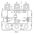
Fig. 1 is a top plan view of an improved metering apparatus in accordance with the disclosed and claimed concept; -
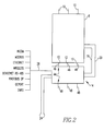
Fig. 2 is a schematic depiction of the metering apparatus ofFig. 1 operationally connected with a circuit breaker; -
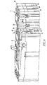
Figs. 3 ,4 , and5 depict the metering apparatus ofFig. 1 being electrically connected with a circuit breaker; and -
Fig. 6 is a schematic depiction of the metering apparatus ofFig. 1 . - Similar numerals refer to similar parts throughout the specification.
- An improved
metering apparatus 4 in accordance with the disclosed and claimed concept is indicated generally inFigs. 1 and6 . Themetering apparatus 4 is structured to be electrically connected with acircuit breaker 8, as is indicated generally inFigs. 2-5 . More particularly, thecircuit breaker 8 includes a number ofline terminals 10 and a number ofload terminals 12 as is generally understood in the relevant art. As employed herein, the expression "a number of" and variations thereof shall refer broadly to any non-zero quantity, including a quantity of one. Themetering apparatus 4 can be advantageously connected with either theline terminals 10 or theload terminals 12 of thecircuit breaker 8, but in the embodiment depicted herein themetering apparatus 4 is depicted as being electrically connected with theload terminals 12. - As can be understood from
Fig. 2 , themetering apparatus 4 includes abell alarm input 16 that is connected with a bell alarm output of thecircuit breaker 8, and further includes anauxiliary switch input 20 that is connected with an auxiliary switch output of thecircuit breaker 8. Thebell alarm input 16 and theauxiliary switch input 20 enable themetering apparatus 4 to determine whether thecircuit breaker 8 has an operational status that is in an ON condition, an OFF condition, or a TRIPPED condition. - The
metering apparatus 4 further includes anauxiliary power input 24 which can be independent of thecircuit breaker 8 and which enables themetering apparatus 4 to be electrically powered even when thecircuit breaker 8 is in an OFF or TRIPPED condition. In the exemplary embodiment depicted herein, theauxiliary power input 24 receives 24 volts DC, but other power inputs can be employed without departing from the present concept. - The
metering apparatus 4 additionally includes aprotocol output 28 that can provide communication to another device using any of a variety of established communications protocols. By way of example, themetering apparatus 4 can be configured to communicate with the other device using the INCOM communications protocol, and the INCOM protocol is the exemplary protocol employed in the depicted embodiment. Alternatively, themetering apparatus 4 can be configured to employ other communications protocols such as, for example and without limitation, - ModBus, Ethernet, Wireless, DeviceNet RS-485, PROFIBUS DP, QCPort, and DNP3, although other communications protocols can be employed without departing from the present concept. Advantageously, the
metering apparatus 4 can be retrofitted to use a different protocol in communicating with another device merely by removing and replacing a printed circuit board of themetering apparatus 4 with another circuit board, as will be set forth in greater detail below. - As can be understood from
Figs. 3-5 , themetering apparatus 4 can be electrically connected with theline terminals 10 or theload terminals 12 of thecircuit breaker 8 by using aconnector 30 and a number offasteners 32 that are received inholes 34 formed in thecircuit breaker 8. Themetering apparatus 4 includes ahousing 36 formed with a number of protrudingribs 38 that are receivable inslots 40 formed on thecircuit breaker 8. When thefasteners 32 are received in theholes 34 and are threadably connected with corresponding portions of theconnector 30, themetering apparatus 4 is affixed to thecircuit breaker 8 and is electrically connected with either theline terminals 10 or theload terminals 12 of the circuit breaker. - As can be understood from
Fig. 6 , themetering apparatus 4 can be said to include aconnection apparatus 44 which, in the exemplary embodiment depicted herein, includes a plurality ofinput terminals 46 and a plurality ofoutput terminals 48. Theinput terminals 46 are connectable with either theline terminals 10 or theload terminals 12 of thecircuit breaker 8, but as suggested elsewhere herein, theinput terminals 46 are depicted in the exemplary embodiment herein as being connected with theload terminals 12. Theoutput terminals 48 can include various types of terminal lugs and wiring configurations as could be provided on thecircuit breaker 8. Theconnection apparatus 44 of themetering apparatus 4 is configured to pass current between theinput terminals 46 and theoutput terminals 48, whereby themetering apparatus 4 can be said to function as an extension of thecircuit breaker 8. - The
metering apparatus 4 can be said to further comprise adetection apparatus 50 that is disposed on thehousing 36 and acommunication apparatus 54 that is likewise disposed on thehousing 36. In this regard, thehousing 36 serves as a support to theconnection apparatus 34, thedetection apparatus 50, and thecommunication apparatus 54, and further can be said to enclose such components in whole or in part. - The
detection apparatus 50 can be said to comprise a measurement printed circuit board (PCB) 52 that includes an analog anddigital sampling system 58 and ameasurement microprocessor 60 that are operationally connected together. The analog anddigital sampling system 58 includes a voltage input for each pole of thecircuit breaker 8 to which themetering apparatus 4 is connected. Thedetection apparatus 50 further includes a Rogowskicoil 64 for each pole of thecircuit breaker 8, and each Rogowskicoil 64 provides a current input to the analog anddigital sampling system 58. - The analog and
digital sampling system 58 provides signals to themeasurement microprocessor 60, which can have its own power input from theauxiliary power input 24. Themeasurement microprocessor 60 can employ the voltage and current data received from the analog anddigital sampling system 58 to derive a variety of operational parameters of thecircuit breaker 8. An exemplary set of operational parameters of thecircuit breaker 8 are set forth in Table A, below, it being noted that other operational parameters or additional operational parameters or both can be provided by themeasurement microprocessor 60 without departing from the present concept.Table A Waveform Capture Power Factor Reverse Energy Currents Ia Ib Ic (No Ig no In) Time Stamping -Real time clock based on protocol Harmonics % Content Peak Demand Forward Energy Volts Va Vb Vc line to line Total
Harmonic
Distortion (17th or better Harmonic)Present Demand Total Energy Frequency Revenue Grade
MeteringRMS
SensingRemote
signal
contacts -breaker status
Aux/BellDigital display
Use DigiView for displayingCommunicate cause of trip (after breaker trips) based on ITIC (CEBEMA) MAC
AddressEvent capture observed conditions curves / data to see voltage sags - The
communication apparatus 54 can be said to comprise a communications printed circuit board (PCB) 56. In the exemplary embodiment depicted herein, thecommunications PCB 56 includes acommunications microprocessor 68 and acommunications receiver transmitter 80. Advantageously, thecommunications PCB 56 is configured to communicate with another device using an established protocol as mentioned elsewhere herein. Further advantageously, thecommunications PCB 56 can be removed from thehousing 36 and replaced with an alternate communications PCB (not expressly depicted herein) that can employ a different protocol to communicate with the other device. Thus, themetering apparatus 4 can be upgraded to communicate using various communications protocols merely by swapping thecommunications PCB 56 with another. - The
communications microprocessor 68 has as inputs the aforementionedbell alarm input 16 andauxiliary switch input 20 that are connected with thecircuit breaker 8. Thecommunications processor 68 further includes inputs from a number ofsettable switches 72 and aCOM address storage 76, both of which are on thecommunications PCB 56. Thecommunication microprocessor 68 can additionally include a power input from theauxiliary power 24. Thecommunications microprocessor 68 further includes aSTATUS output 78 that includes a status light on thehousing 36 and that communicates to another device the status of thecircuit breaker 8, i.e., whether the circuit breaker is an ON condition, an OFF condition, or a TRIPPED condition. - The
communications microprocessor 68 derives the status of thecircuit breaker 8 based upon inputs from thebell alarm 16 and theauxiliary switch input 20 using a known truth table. More particularly, thebell alarm input 16 indicates the handle position of thecircuit breaker 8, which indicates whether or not thecircuit breaker 8 is in a TRIPPED condition. Theauxiliary input switch 20 indicates whether the contacts of thecircuit breaker 8 are in an open or closed condition. By analyzing the inputs from thebell alarm input 16 and theauxiliary switch input 20, thecommunications microprocessor 68 can derive whether thecircuit breaker 8 is an ON condition, an OFF condition, or a TRIPPED condition. Thecommunications microprocessor 60 then can communicate to another device such a status of thecircuit breaker 8 using theSTATUS output 78 and can also visually provide the status by illuminating the status light that is disposed on thehousing 36. - The
communications microprocessor 68 further provides signals to thecommunications receiver transmitter 80 which employs an established protocol to communicate with another device using theprotocol output 28. Theprotocol output 28 is connected with the other device (not expressly depicted herein) and employs one of a number of established protocols, an exemplary number of which are mentioned elsewhere herein. The other device to which theprotocol output 28 is connected can be the same other device as that to which theSTATUS output 78 is provided or may be yet another device. Thecommunications receiver transmitter 80 is additionally connected with a transmit (Tx)status light 86 and a receiver (Rx)status light 92 which visually indicate when thecommunications transmitter 80 is transmitting and receiving, respectively, signals to and from, respectively, the other device. - The
communications receiver transmitter 80 receives signals from thecommunications microprocessor 68 that are representative of one or more of the operational parameters set forth in Table A and that are, in turn, received from themeasurement microprocessor 60 and have been derived from input to the analog anddigital sampling system 58. As such, the status of thecircuit breaker 8, which is communicated using theSTATUS output 78 from themicroprocessor 68, as well as the operational parameters of the circuit breaker 8 (such as are mentioned in Table A) that are transmitted from thecommunications receiver transmitter 80 using theprotocol output 28, are derived from voltage, current, and other inputs to the analog anddigital sampling system 58. - The
metering apparatus 4 can further advantageously be configured according to the environment of its connection withcircuit breaker 8. For instance, theinput terminals 46 of the metering apparatus can be connected with either theline terminals 10 or theload terminals 12 of thecircuit breaker 8. In circumstance where theinput terminals 46 are connected with theline terminals 10 of thecircuit breaker 8, thecommunications receiver transmitter 80 might communicate a reverse energy value to the other device. Themetering apparatus 4 thus can be configured to instead report forward energy instead of reverse energy in order to maintain consistency withother metering apparatuses 4 andcircuit breakers 8, by way of example. - Moreover, the poles of the
metering apparatus 4 can be reconfigured depending upon the needs of the application. As a default, the poles of themetering apparatus 4, as represented by the threeinput terminals 46 inFigs. 1 and6 , are designated as A, B, and C when going left-to-right from the perspective ofFigs. 1 and6 . If necessary, the poles can be reconfigured to be designated as C, B, and A when moving from left-to-right from the perspective ofFigs. 1 and6 . Such a re-designation of the poles may be useful in any of a variety of applications, such as if thecircuit breakers 8 andmetering apparatuses 4 of a given switchgear cabinet (not expressly depicted herein) are mounted in two different orientations. This is a typical application since the line terminals of the switchgear cabinet are typically situated centrally on a switchgear cabinet and the load terminals are disposed peripherally on the switchgear cabinet. In such a scenario, themetering apparatuses 4 may be connected with the peripheral, load ends of thecircuit breakers 8. However, the vertically uppermost pole of ametering apparatus 4 at one of the side of the switchgear cabinet might have a default designation of A whereas the vertically uppermost pole of ametering apparatus 4 on the opposite side of the switchgear cabinet might have a default designation of C. It thus may be desirable to alter the designation of such an uppermost pole from C to A and in order that all of the uppermost poles are A, and to re-designate a lowermost pole from A to C in order that all of the lowest poles are designated as C. Other uses of such a feature will be apparent. - It thus can be seen that the
improved metering apparatus 4 can be connected with the poles of thecircuit breaker 8 and can provide metering of various operational parameters and operational conditions of thecircuit breaker 8. Such operational parameters and conditions can be communicated to another device using any of a variety of known protocols, which protocol can be changed merely by swapping thecommunications PCB 56 with another. Themetering apparatus 4 additionally may include a power input that is independent of thecircuit breaker 8 in order to enable themetering apparatus 4 to remain powered even if acircuit breaker 8 is in an OFF or TRIPPED condition. - While specific embodiments of the invention have been described in detail, it will be appreciated by those skilled in the art that various modifications and alternatives to those details could be developed in light of the overall teachings of the disclosure. Accordingly, the particular arrangements disclosed are meant to be illustrative only and not limiting as to the scope of invention which is to be given the full breadth of the claims appended and any and all equivalents thereof.
- 4.
- Metering apparatus
- 8.
- Circuit breaker
- 10.
- CB Terminals (line)
- 12.
- CB Terminals (load)
- 16.
- Bell alarm input
- 20.
- Auxiliary switch input
- 24.
- Auxiliary power input
- 28.
- Protocol output
- 30.
- Connector
- 32.
- Fasteners
- 34.
- Holes
- 36.
- Housing
- 38.
- Ribs
- 40.
- Slots
- 44.
- Connection Apparatus
- 46.
- Input Terminals (PM3)
- 48.
- Output Terminals (PM3)
- 50.
- Detection Apparatus
- 52.
- Measurement PCB
- 54.
- Communication apparatus
- 56.
- Communications PCB
- 58.
- Analog and Digital Sampling System
- 60.
- Measurement microprocessor
- 64.
- Rogowski coil inputs
- 68.
- Communications microprocessor
- 72.
- Switches
- 76.
- COM address storage
- 78.
- STATUS output
- 80.
- Communications receiver transmitter
- 86.
- Transmit (Tx) status light
- 92.
- Receive (Rx) status light
Claims (15)
- A metering apparatus (4) comprising:a support (36);a connection apparatus (44) disposed on the support and structured to be electrically connected with a circuit interrupter (8);a detection apparatus (50) disposed on the support and structured to detect at least a first operational aspect of the circuit interrupter;a communication apparatus (54) in communication with the detection apparatus, the communication apparatus being disposed on the support and being structured to communicate to another device at least a first parameter of the circuit interrupter based at least in part upon the at least first operational aspect; andat least one of the detection apparatus and the communication apparatus comprising a power input (24) structured to be electrically connected with a power source external to the circuit interrupter to make current available to the at least one of the detection apparatus and the communication apparatus.
- The metering apparatus of Claim 1 wherein the detection apparatus is structured to detect as the at least first operational aspect at least one of a condition of a bell alarm of the circuit interrupter and a condition of an auxiliary switch of the circuit interrupter, and wherein the communication apparatus is structured to communicate to the another device as the at least first parameter of the circuit interrupter at least one of an ON status, an OFF status, and a TRIPPED status of the circuit interrupter.
- The metering apparatus of Claim 2 wherein the detection apparatus is structured to additionally detect as the at least first operational aspect a voltage and a current for each of a number of poles of the circuit interrupter, and wherein the communication apparatus is structured to further communicate to the another device as the at least first parameter of the circuit interrupter a plurality of additional parameters of the circuit interrupter including one or more of a power factor, a reverse energy, a total energy, a total harmonic distortion, a harmonic percentage content, a waveform capture, and root-mean-squared voltage, a peak demand, and a present demand of the circuit interrupter.
- The metering apparatus of Claim 1 wherein the communication apparatus employs a predetermined communications protocol to communicate to the another device the at least first parameter of the circuit interrupter, the communication apparatus being removable from the metering apparatus and replaceable with another communication apparatus that employs another predetermined communications protocol to communicate to the another device the at least first parameter of the circuit interrupter.
- The metering apparatus of Claim 1 wherein the connection apparatus comprises a number of first terminals (46) and a number of second terminals (48), the number of first terminals being structured to be coupled with a number of terminals (10, 12) of the circuit interrupter and to pass current between the number of terminals of the circuit interrupter and the number of second terminals of the detection apparatus.
- A metering apparatus (4) comprising:a support (36);a connection apparatus (44) disposed on the support and structured to be electrically connected with a circuit interrupter (8);a detection apparatus (50) disposed on the support and structured to detect at least a first operational aspect of the circuit interrupter; anda communication apparatus (54) in communication with the detection apparatus, the communication apparatus being disposed on the support and being structured to communicate to another device a plurality of parameters of the circuit interrupter based at least in part upon the at least first operational aspect and including at least one of an ON status, an OFF status, and a TRIPPED status of the circuit interrupter and further including a number of additional parameters comprising one or more of a current, a voltage, a power factor, a reverse energy, a total energy, a total harmonic distortion, a harmonic percentage content, a waveform capture, and root-mean-squared voltage, a peak demand, and a present demand of the circuit interrupter.
- The metering apparatus of Claim 6 wherein at least one of the detection apparatus and the communication apparatus comprises a power input (24) structured to be electrically connected with a power source external to the circuit interrupter to make current available to the at least one of the detection apparatus and the communication apparatus.
- The metering apparatus of Claim 1 wherein the detection apparatus is structured to detect as the at least first operational aspect at least one of a condition of a bell alarm of the circuit interrupter and a condition of an auxiliary switch of the circuit interrupter, and is structured to additionally detect as the at least first operational aspect a voltage and a current for each of a number of poles of the circuit interrupter, wherein the communication apparatus is structured to communicate to the another device the at least one of an ON status, an OFF status, and a TRIPPED status of the circuit interrupter based at least in part upon the at least one of a condition of a bell alarm and a condition of an auxiliary switch, and wherein the communication apparatus is structured to communicate to the another device the number of additional parameters based at least in part upon at least one of the voltage and the current.
- The metering apparatus of Claim 6 wherein the communication apparatus employs a predetermined communications protocol to communicate to the another device the plurality of parameters of the circuit interrupter, the communication apparatus being removable from the metering apparatus and replaceable with another communication apparatus that employs another predetermined communications protocol to communicate to the another device the plurality of parameters of the circuit interrupter.
- The metering apparatus of Claim 6 wherein the connection apparatus comprises a number of first terminals (46) and a number of second terminals (48), the number of first terminals being structured to be coupled with a number of terminals (10, 12) of the circuit interrupter and to pass current between the number of terminals of the circuit interrupter and the number of second terminals of the detection apparatus.
- A metering apparatus (4) comprising:a support (36);a connection apparatus (44) disposed on the support and comprising a number of first terminals (46) and a number of second terminals (48), the number of first terminals being structured to be coupled with a number of terminals (10, 12) of a circuit interrupter (8) and to pass current between the number of terminals of the circuit interrupter and the number of second terminals of the detection apparatus;a detection apparatus (50) disposed on the support and structured to detect at least a first operational aspect of the circuit interrupter; anda communication apparatus (54) in communication with the detection apparatus, the communication apparatus being disposed on the support and being structured to communicate to another device at least a first parameter of the circuit interrupter based at least in part upon the at least first operational aspect and including at least one of an ON status, an OFF status, and a TRIPPED status of the circuit interrupter.
- The metering apparatus of Claim 11 wherein at least one of the detection apparatus and the communication apparatus comprises a power input (24) structured to be electrically connected with a power source external to the circuit interrupter to make current available to the at least one of the detection apparatus and the communication apparatus.
- The metering apparatus of Claim 11 wherein the detection apparatus is structured to detect as the at least first operational aspect at least one of a condition of a bell alarm of the circuit interrupter and a condition of an auxiliary switch of the circuit interrupter, and wherein the communication apparatus is structured to communicate to the another device the at least one of an ON status, an OFF status, and a TRIPPED status of the circuit interrupter based at least in part upon the at least one of a condition of a bell alarm and a condition of an auxiliary switch.
- The metering apparatus of Claim 13 wherein the detection apparatus is structured to additionally detect as the at least first operational aspect a voltage and a current for each of a number of poles of the circuit interrupter, and wherein the communication apparatus is structured to further communicate to the another device as the at least first parameter of the circuit interrupter a plurality of additional parameters of the circuit interrupter including one or more of a power factor, a reverse energy, a total energy, a total harmonic distortion, a harmonic percentage content, a waveform capture, and root-mean-squared voltage, a peak demand, and a present demand of the circuit interrupter.
- The metering apparatus of Claim 11 wherein the communication apparatus employs a predetermined communications protocol to communicate to the another device the at least first parameter of the circuit interrupter, the communication apparatus being removable from the metering apparatus and replaceable with another communication apparatus that employs another predetermined communications protocol to communicate to the another device the at least first parameter of the circuit interrupter.
Applications Claiming Priority (1)
| Application Number | Priority Date | Filing Date | Title |
|---|---|---|---|
| US12/792,460 US8643501B2 (en) | 2010-06-02 | 2010-06-02 | Metering apparatus |
Publications (2)
| Publication Number | Publication Date |
|---|---|
| EP2393101A2 true EP2393101A2 (en) | 2011-12-07 |
| EP2393101A3 EP2393101A3 (en) | 2013-05-01 |
Family
ID=44475100
Family Applications (1)
| Application Number | Title | Priority Date | Filing Date |
|---|---|---|---|
| EP11004459.1A Withdrawn EP2393101A3 (en) | 2010-06-02 | 2011-05-31 | Metering apparatus |
Country Status (4)
| Country | Link |
|---|---|
| US (1) | US8643501B2 (en) |
| EP (1) | EP2393101A3 (en) |
| CN (1) | CN102419418A (en) |
| CA (1) | CA2741932A1 (en) |
Families Citing this family (8)
| Publication number | Priority date | Publication date | Assignee | Title |
|---|---|---|---|---|
| US9054516B2 (en) * | 2011-07-20 | 2015-06-09 | Siemens Industry, Inc. | Circuit breaker trip notification systems and methods |
| US8982515B2 (en) * | 2012-05-22 | 2015-03-17 | Eaton Corporation | Apparatus for a circuit interrupter |
| GB2530498A (en) * | 2014-09-23 | 2016-03-30 | Martin Bills | A diagnostic and communication device for circuit breakers |
| US10598731B2 (en) * | 2014-11-10 | 2020-03-24 | Eaton Intelligent Power Limited | Circuit interrupter and system for testing the same |
| US10008353B2 (en) | 2015-10-29 | 2018-06-26 | Eaton Intelligent Power Limited | Metering apparatus, system and distribution system including same |
| USD865691S1 (en) * | 2016-06-16 | 2019-11-05 | Copernicus Educational Products Inc. | Stackable media storage container |
| US11211786B2 (en) * | 2017-11-08 | 2021-12-28 | Abb Schweiz Ag | Smart module for a circuit breaker |
| US11139131B2 (en) | 2018-12-21 | 2021-10-05 | Abb Schweiz Ag | Electromechanical relay with data collection cover |
Family Cites Families (14)
| Publication number | Priority date | Publication date | Assignee | Title |
|---|---|---|---|---|
| US4250476A (en) * | 1979-11-13 | 1981-02-10 | S & C Electric Company | Auxiliary switch for indicating the condition of a circuit-interrupting device |
| GB8713791D0 (en) * | 1987-06-12 | 1987-07-15 | Bicc Plc | Electric circuit breaking apparatus |
| US5384712A (en) | 1991-08-15 | 1995-01-24 | Eaton Corporation | Energy monitoring system for a plurality of local stations with snapshot polling from a central station |
| US5754113A (en) * | 1996-10-28 | 1998-05-19 | Eaton Corporation | Circuit monitor for plural electrical switching apparatus |
| US6262880B1 (en) * | 2000-04-05 | 2001-07-17 | Eaton Corporation | Circuit breaker mounting assembly with moveable remote terminal block |
| US6538870B2 (en) | 2001-02-02 | 2003-03-25 | Eaton Corporation | Circuit breaker and electrical distribution panel employing the same |
| US7515400B2 (en) | 2003-02-28 | 2009-04-07 | Toyota Motor Sales, U.S.A., Inc. | Circuit breaker box and monitoring system |
| GB0323645D0 (en) * | 2003-10-09 | 2003-11-12 | Kelman Ltd | System and apparatus for detecting and monitoring circuit breaker operation |
| US7362207B2 (en) | 2005-05-24 | 2008-04-22 | Eaton Corporation | Electrical switching apparatus and limiter including trip indicator member |
| FR2901912B1 (en) * | 2006-05-31 | 2008-08-15 | Schneider Electric Ind Sas | DEVICE FOR DETECTING THE THREE STATES OF A CIRCUIT BREAKER |
| US7609170B2 (en) * | 2007-03-26 | 2009-10-27 | Jon Andrew Bickel | Interactive interface within a monitoring and control device |
| US7558040B2 (en) | 2007-04-26 | 2009-07-07 | Eaton Corporation | Trip indicator member, and limiter and electrical switching apparatus including a plurality of trip indicator members |
| US20090051557A1 (en) * | 2007-08-20 | 2009-02-26 | Beatty William E | Method and electrical switching apparatus including a number of accessories employing wireless communication |
| CN201477187U (en) * | 2009-08-11 | 2010-05-19 | 武汉华工先舰电气股份有限公司 | Protection characteristic tester of DC circuit breaker |
-
2010
- 2010-06-02 US US12/792,460 patent/US8643501B2/en active Active
-
2011
- 2011-05-31 EP EP11004459.1A patent/EP2393101A3/en not_active Withdrawn
- 2011-06-02 CN CN2011101895227A patent/CN102419418A/en active Pending
- 2011-06-02 CA CA2741932A patent/CA2741932A1/en not_active Abandoned
Non-Patent Citations (1)
| Title |
|---|
| None |
Also Published As
| Publication number | Publication date |
|---|---|
| US8643501B2 (en) | 2014-02-04 |
| US20110298625A1 (en) | 2011-12-08 |
| CA2741932A1 (en) | 2011-12-02 |
| CN102419418A (en) | 2012-04-18 |
| EP2393101A3 (en) | 2013-05-01 |
Similar Documents
| Publication | Publication Date | Title |
|---|---|---|
| EP2393101A2 (en) | Metering apparatus | |
| US7453684B2 (en) | Current inputs interface for an electrical device | |
| US8447545B2 (en) | Module for measuring the current flowing in a conductor distribution of a low-voltage distribution board | |
| AU2008339532B2 (en) | Trip unit and electrical switching apparatus including a movable indicator to indicate selection of an arc reduction maintenance system current condition | |
| US9136074B2 (en) | Residual-current circuit breaker | |
| EP2109205A1 (en) | Remote operation control of a MV/LV transformer station and remote signalling of faults | |
| US10529520B2 (en) | Metering apparatus, system and distribution system including same | |
| RU2321916C2 (en) | Switch with built-in current and/or voltage sensor | |
| RU2683416C2 (en) | Device for measuring at least one magnitude of electric current which should circulate in electrical device and unit containing such device | |
| EP2807664B1 (en) | Combined transformer for power system | |
| RU2008107986A (en) | PROCESSING DEVICE | |
| US20130222962A1 (en) | Circuit board meter for circuit breakers | |
| WO2008008726A3 (en) | Current monitoring device for high voltage electric power lines | |
| KR20200122140A (en) | Circuit Breaker having detachable Electricity Measuring Device | |
| CN102487193A (en) | Self-powered overcurrent protection device | |
| JP2012034570A (en) | Method and apparatus for use in monitoring operation of electrical switchgear | |
| US11394202B1 (en) | Alternating current time-sharing outlets and switch box | |
| Fidigatti et al. | Effect of harmonic pollution on low voltage overcurrent protection | |
| CN210669514U (en) | Motor protector for frequency conversion loop | |
| JP7233355B2 (en) | Mounting terminal block for circuit breaker | |
| AU2012396428A1 (en) | Current transformer and load interrupter having such a current transformer | |
| CN218896586U (en) | Knife switch | |
| CN114094605B (en) | Low-voltage meter phase modulation device and method, electronic equipment and storage medium | |
| US20220302694A1 (en) | System, circuit breaker, display unit and display holder | |
| BE1020022A5 (en) | SWITCH BOX WITH MEASURING FUNCTION, MEASURING MODULE THEREFOR AND A DOMOTIC SYSTEM CONTAINING SUCH A SWITCH BOX. |
Legal Events
| Date | Code | Title | Description |
|---|---|---|---|
| AK | Designated contracting states |
Kind code of ref document: A2 Designated state(s): AL AT BE BG CH CY CZ DE DK EE ES FI FR GB GR HR HU IE IS IT LI LT LU LV MC MK MT NL NO PL PT RO RS SE SI SK SM TR |
|
| AX | Request for extension of the european patent |
Extension state: BA ME |
|
| PUAI | Public reference made under article 153(3) epc to a published international application that has entered the european phase |
Free format text: ORIGINAL CODE: 0009012 |
|
| PUAL | Search report despatched |
Free format text: ORIGINAL CODE: 0009013 |
|
| AK | Designated contracting states |
Kind code of ref document: A3 Designated state(s): AL AT BE BG CH CY CZ DE DK EE ES FI FR GB GR HR HU IE IS IT LI LT LU LV MC MK MT NL NO PL PT RO RS SE SI SK SM TR |
|
| AX | Request for extension of the european patent |
Extension state: BA ME |
|
| RIC1 | Information provided on ipc code assigned before grant |
Ipc: H01H 9/16 20060101ALI20130322BHEP Ipc: H01H 71/08 20060101AFI20130322BHEP |
|
| 17P | Request for examination filed |
Effective date: 20131104 |
|
| RBV | Designated contracting states (corrected) |
Designated state(s): AL AT BE BG CH CY CZ DE DK EE ES FI FR GB GR HR HU IE IS IT LI LT LU LV MC MK MT NL NO PL PT RO RS SE SI SK SM TR |
|
| GRAP | Despatch of communication of intention to grant a patent |
Free format text: ORIGINAL CODE: EPIDOSNIGR1 |
|
| INTG | Intention to grant announced |
Effective date: 20140704 |
|
| RAP1 | Party data changed (applicant data changed or rights of an application transferred) |
Owner name: EATON CORPORATION |
|
| STAA | Information on the status of an ep patent application or granted ep patent |
Free format text: STATUS: THE APPLICATION IS DEEMED TO BE WITHDRAWN |
|
| 18D | Application deemed to be withdrawn |
Effective date: 20141115 |