EP2392948A2 - Sich selbst ausrichtende Lichtquelle und Detektoranordnung - Google Patents
Sich selbst ausrichtende Lichtquelle und Detektoranordnung Download PDFInfo
- Publication number
- EP2392948A2 EP2392948A2 EP11167346A EP11167346A EP2392948A2 EP 2392948 A2 EP2392948 A2 EP 2392948A2 EP 11167346 A EP11167346 A EP 11167346A EP 11167346 A EP11167346 A EP 11167346A EP 2392948 A2 EP2392948 A2 EP 2392948A2
- Authority
- EP
- European Patent Office
- Prior art keywords
- light source
- assembly
- sensor
- lamp assembly
- detector assembly
- Prior art date
- Legal status (The legal status is an assumption and is not a legal conclusion. Google has not performed a legal analysis and makes no representation as to the accuracy of the status listed.)
- Granted
Links
Images
Classifications
-
- G—PHYSICS
- G01—MEASURING; TESTING
- G01N—INVESTIGATING OR ANALYSING MATERIALS BY DETERMINING THEIR CHEMICAL OR PHYSICAL PROPERTIES
- G01N21/00—Investigating or analysing materials by the use of optical means, i.e. using sub-millimetre waves, infrared, visible or ultraviolet light
- G01N21/84—Systems specially adapted for particular applications
- G01N21/85—Investigating moving fluids or granular solids
- G01N21/8507—Probe photometers, i.e. with optical measuring part dipped into fluid sample
-
- G—PHYSICS
- G01—MEASURING; TESTING
- G01V—GEOPHYSICS; GRAVITATIONAL MEASUREMENTS; DETECTING MASSES OR OBJECTS; TAGS
- G01V8/00—Prospecting or detecting by optical means
- G01V8/10—Detecting, e.g. by using light barriers
Definitions
- This invention pertains generally to the measurement of optical absorbance and, more particularly, to a self-aligning light source and detector assembly for use in measuring optical absorbance.
- Instruments for measuring optical absorbance are widely used in fields such as industrial, medical, and food applications. Such instruments generally include a light source and a detector, and for consistent, reliable readings, it is important that the light source and detector remain in proper alignment, particularly when the instruments are used in critical applications.
- Light sources such as incandescent lamps tend to burn out and require periodic replacement, which can easily result in improper alignment between light source and detector, particularly in smaller, more compact instruments. If the light source cannot be replaced in the field, then the instrument either has to be replaced or removed from service and sent away for repair, both of which can be expensive and disruptive.
- Another object of the invention is to provide a light source and detector assembly of the above character, in which the light source and detector are self-aligning.
- a self-aligning light source and detector assembly having a sensor support mounted in a predetermined, fixed position, a light source holder mounted in a predetermined, fixed position relative to the sensor support, a sensor mounted in a fixed position on the sensor support, and a lamp assembly removably mounted to the light source holder in a predetermined position defined by mating surfaces which engage each other and seat the lamp assembly in the predetermined position whenever the lamp assembly is installed in the holder.
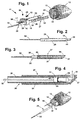
- the light source and detector assembly 11 is illustrated in connection with a probe head 12 having an externally threaded base 13 that attaches to a generally cylindrical housing (not shown).
- a mounting block 16 is attached to the inner face of the base 13 by a mounting screw 17.
- the block is generally rectangular, with arcuately curved end surfaces 18 of slightly smaller diameter than the inner wall of the housing.
- Axially extending parallel bores 19, 21 extend through the mounting block on opposite sides of the mounting screw in alignment with corresponding bores 22, 23 in the base.
- the probe head 12 can as well be designed to attach to a disposable container, such as for example a disposable fermentation bag having flexible walls for single-use in a biotechnological process.
- a disposable container such as for example a disposable fermentation bag having flexible walls for single-use in a biotechnological process.
- the threaded base 13 can be attached to a fixture in the disposable container wall or the base 13 can be designed to be welded to the wall of the disposable container.
- the light source consists of a lamp assembly 26 which is removably mounted in a tubular holder 27.
- the tube holder is mounted in bore 19, passes through bore 22, and extends from the outer end of the probe head 12.
- the lamp assembly includes an elongated tubular body 28, with a lamp 29 mounted in a socket 31 at one end thereof and leads 32 extending from the socket, through the tubular body for connection to a power source in the probe housing.
- the lamp holder has a tubular body 34 with an aperture 36 in the side wall thereof toward the distal or outer end of the tube and a mirror 37 mounted in the distal end portion of the tube for directing light from the lamp through the aperture toward the sensor.
- the mirror is inclined at an angle of 45 degrees to the axis of the lamp holder, and the light from the lamp is reflected in a direction perpendicular to that axis.
- the aperture 36 can be tightly covered by a transparent window, e.g. made of quartz, sapphire or a transparent plastic depending on the wavelength used for measurement.
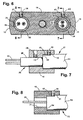
- the inner end of the lamp holder abuts against a radial shoulder 39 in bore 19 and is secured in place by a set screw 42 in the mounting block which is received in a key way or notch 43 in the outer wall of the lamp holder tube.
- the lamp assembly is inserted coaxially into the lamp holder through the inner end of the lamp holder tube and has a radial shoulder 46 which abuts against a corresponding shoulder 47 in the tube.
- the lamp assembly is locked in position in the lamp holder by a set screw 48 in the mounting block which is tightened against the outer wall of the tube.
- the lamp assembly can be removed from the holder and then reinserted and locked in a predetermined axial position.
- the inner end portion of the lamp assembly projects from the inner end of the holder and can be used for rotating the lamp assembly within the holder and mount for maximum optical signal before seating the set screw.
- the detector assembly includes a light detector or sensing element 51 and a sensor support 52.
- the sensor support has an elongated tubular body 53 which is mounted in bore 21, passes through bore 23, and extends from the outer end of the probe head.
- the inner end of the support tube abuts against a radial shoulder 54 in bore 21 and is secured in place by a set screw 56 in the mounting block.
- This set screw is received in a key way or notch 57 in the outer wall of the support tube.
- Light detector or sensing element 51 is mounted on the side wall of the support tube near the distal end of the tube directly opposite and facing the aperture and mirror in the lamp holder, with leads 59 from the sensing element extending through the tube for connection to circuitry in the probe housing.
- the probe head is separated from the housing, the set screw 48 is removed, and the lamp assembly is withdrawn from the inner end of the lamp holder, as illustrated in Figure 5 .
- the old lamp is removed from the socket, and a new lamp is installed in its place.
- the lamp assembly is then reinserted into the holder until shoulder 46 abuts against shoulder 47 and turned to maximize the signal from the detector. With the lamp assembly thus seated in its predetermined position and oriented for best signal, set screw 48 is tightened against the lamp assembly to lock it in place.
- the lengths of the lamp holder and the detector assembly are such that when the inner ends of the lamp holder and sensor support tubes are seated against the shoulders in the mounting block bores and the set screws are tightened in the key ways, the sensing element is directly opposite the aperture in the lamp holder, and light reflected from the lamp by the mirror is focused on the sensing element.
- the alignment is self-guided and will always be the same whether the device is assembled in the factory or serviced in the field.
- the invention has a number of important features and advantages.
- the light source and detector are self-aligning, and the light source lamp can be replaced in the field without disturbing that alignment.
- the lamp assembly is independent of the lamp holder and projection mirror.
- the lamp assembly can easily be removed for lamp replacement without removal of the lamp holder and mirror which are affixed to the mounting block and probe head.
- the lengths of the lamp holder and the detector assembly are fixed so that when each assembly is inserted into the mounting block, its position is controlled and the two assemblies are automatically aligned to each other.
- the mounting block 16 with the lamp assembly fixed in bore 19 and the detector assembly fixed in bore 21 forms a readily aligned optical assembly.
- This assembly can be connected to various different kinds of probe heads as long as they provide an appropriate base with bores corresponding to both the tubular holder 27 of the lamp assembly and the tubular holder 53 of the detector assembly.
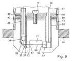
- Figure 9 shows the complete probe assembly with the lamp holder and the detector holder mounted in the mounting block 16, which is fixed to the probe head 12.
- the threaded base 13 of the probe head 12 is screwed to a cylindrical probe housing 67.
- the sensor assembly and the detector assembly do not protrude from the probe head 12.
- the probe head 12 comprises two facing apertures which provide a passage for a light beam 69 reflected from mirror 37.
- the apertures are sealingly closed by windows 61 and 63.
- Windows 61 and 63 can be made of any material transparent for the light emitted by the lamp 29. For example, they can be made of quartz, quartz glass, sapphire or transparent plastics.
- the probe head 12 is connected to a container wall 65 of a container comprising a medium, for example a liquid or a liquid mixture used in an industrial process.
- a container wall 65 of a container comprising a medium, for example a liquid or a liquid mixture used in an industrial process.
- a medium for example a liquid or a liquid mixture used in an industrial process.
- disposable containers are used in pharmaceutical or biotechnological processes.
- Disposable containers are usually made of plastics that can be sterilized before starting the pharmaceutical or biotechnological process and that can be disposed of after the process has been completed.
- Disposable containers can be rigid or flexible tubes or flexible bags, for example disposable fermenters.
- the container wall 65 can be glued or welded to the probe head 12. It can also comprise a fixture comprising for example a bayonet fitting or an internal thread for receiving the probe head 12.
- the readily aligned optical assembly comprising the mounting block 16 with the lamp assembly fixed in bore 19 and the detector assembly fixed in bore 21 can be used several times with different disposable containers having a corresponding probe head 12 fixed in or connected to a container wall 65. After use the probe heads can be disposed of together with the container. The expensive optical assembly, however, can be used again.
Landscapes
- Physics & Mathematics (AREA)
- General Physics & Mathematics (AREA)
- Life Sciences & Earth Sciences (AREA)
- General Health & Medical Sciences (AREA)
- Analytical Chemistry (AREA)
- Biochemistry (AREA)
- Chemical & Material Sciences (AREA)
- Health & Medical Sciences (AREA)
- Immunology (AREA)
- Pathology (AREA)
- General Life Sciences & Earth Sciences (AREA)
- Geophysics (AREA)
- Investigating Or Analysing Materials By Optical Means (AREA)
- Fastening Of Light Sources Or Lamp Holders (AREA)
Applications Claiming Priority (2)
| Application Number | Priority Date | Filing Date | Title |
|---|---|---|---|
| US12/795,501 US8651702B2 (en) | 2010-06-07 | 2010-06-07 | Self-aligning light source and detector assembly |
| US12/975,597 US8542363B2 (en) | 2010-12-22 | 2010-12-22 | Self-aligning light source and detector assembly for absorbance measurement |
Publications (3)
| Publication Number | Publication Date |
|---|---|
| EP2392948A2 true EP2392948A2 (de) | 2011-12-07 |
| EP2392948A3 EP2392948A3 (de) | 2017-07-26 |
| EP2392948B1 EP2392948B1 (de) | 2020-11-18 |
Family
ID=44652106
Family Applications (1)
| Application Number | Title | Priority Date | Filing Date |
|---|---|---|---|
| EP11167346.3A Active EP2392948B1 (de) | 2010-06-07 | 2011-05-24 | Sich selbst ausrichtende Lichtquelle und Detektoranordnung |
Country Status (2)
| Country | Link |
|---|---|
| EP (1) | EP2392948B1 (de) |
| CN (1) | CN102269694B (de) |
Cited By (2)
| Publication number | Priority date | Publication date | Assignee | Title |
|---|---|---|---|---|
| WO2012134820A1 (en) * | 2011-03-25 | 2012-10-04 | Sencal Llc | Optical sensors for monitoring biopharmaceutical solutions in single-use containers |
| US9575087B2 (en) | 2012-09-06 | 2017-02-21 | Parker-Hannifin Corporation | Risk-managed, single-use, pre-calibrated, pre-sterilized sensors for use in bio-processing applications |
Families Citing this family (1)
| Publication number | Priority date | Publication date | Assignee | Title |
|---|---|---|---|---|
| CN105353425B (zh) * | 2015-12-23 | 2018-05-08 | 深圳市艾礼安安防设备有限公司 | 一种采用辅助光校准主动红外探测器的方法 |
Family Cites Families (10)
| Publication number | Priority date | Publication date | Assignee | Title |
|---|---|---|---|---|
| US2918585A (en) * | 1958-04-11 | 1959-12-22 | Edward B Farmer | Photoelectric mount |
| US3411005A (en) * | 1966-01-24 | 1968-11-12 | Automation Devices Inc | Compact infrared detector systems with regulated power supply |
| US3847482A (en) * | 1972-07-10 | 1974-11-12 | Bio Data Corp | Apparatus for detecting a change in turbidity of a solution |
| US5320808A (en) * | 1988-08-02 | 1994-06-14 | Abbott Laboratories | Reaction cartridge and carousel for biological sample analyzer |
| US5521376A (en) * | 1994-04-20 | 1996-05-28 | The United States Of America As Represented By The Secretary Of The Navy | Optical motion sensor for an underwater object |
| CN2364457Y (zh) * | 1998-11-20 | 2000-02-16 | 官庆福 | 液体用光透过率测定装置的改良 |
| DE20111588U1 (de) * | 2000-07-18 | 2001-11-15 | Leuze Electronic Gmbh + Co, 73277 Owen | Befestigungsvorrichtung für einen otpischen Sensor |
| US7095500B2 (en) * | 2004-01-30 | 2006-08-22 | Nalco Company | Interchangeable tip-open cell fluorometer |
| US7350939B2 (en) * | 2005-05-20 | 2008-04-01 | Infocus Corporation | Alignment structure for use with a light source and/or a light gathering reflector |
| US20080144033A1 (en) * | 2006-12-13 | 2008-06-19 | Scully Signal Company | Optical level detection probe for fluid overfill prevention system |
-
2011
- 2011-05-24 EP EP11167346.3A patent/EP2392948B1/de active Active
- 2011-06-07 CN CN201110159336.9A patent/CN102269694B/zh active Active
Non-Patent Citations (1)
| Title |
|---|
| None |
Cited By (5)
| Publication number | Priority date | Publication date | Assignee | Title |
|---|---|---|---|---|
| WO2012134820A1 (en) * | 2011-03-25 | 2012-10-04 | Sencal Llc | Optical sensors for monitoring biopharmaceutical solutions in single-use containers |
| US8817259B2 (en) | 2011-03-25 | 2014-08-26 | Parker-Hannifin Corporation | Optical sensors for monitoring biopharmaceutical solutions in single-use containers |
| US9568420B2 (en) | 2011-03-25 | 2017-02-14 | Parker-Hannifin Corporation | Optical sensors for monitoring biopharmaceutical solutions in single-use containers |
| US11506597B2 (en) | 2011-03-25 | 2022-11-22 | Parker Hannifin Corporation | Optical sensors for monitoring biopharmaceutical solutions in single-use containers |
| US9575087B2 (en) | 2012-09-06 | 2017-02-21 | Parker-Hannifin Corporation | Risk-managed, single-use, pre-calibrated, pre-sterilized sensors for use in bio-processing applications |
Also Published As
| Publication number | Publication date |
|---|---|
| EP2392948A3 (de) | 2017-07-26 |
| EP2392948B1 (de) | 2020-11-18 |
| CN102269694B (zh) | 2016-03-23 |
| CN102269694A (zh) | 2011-12-07 |
Similar Documents
| Publication | Publication Date | Title |
|---|---|---|
| US8542363B2 (en) | Self-aligning light source and detector assembly for absorbance measurement | |
| US9400243B2 (en) | Disposable sensor head and disposable container | |
| US12085416B2 (en) | Universal sensor fitting for process applications | |
| CN103210298A (zh) | 利用一次性流动池的微型uv传感器 | |
| US5905271A (en) | Inline optical sensor with vernier pathlength adjustment and photometric calibration | |
| EP2392948B1 (de) | Sich selbst ausrichtende Lichtquelle und Detektoranordnung | |
| US9377411B2 (en) | Transflexion probe and transflective sensor | |
| US20150265828A1 (en) | Adapters | |
| US9976991B2 (en) | Optical gas sensor | |
| WO2010027982A2 (en) | Adapter mechanism for handheld spectral sensing device | |
| EP0482883A1 (de) | Flüssigkeitspegelanzeiger | |
| US11751949B2 (en) | Medical fastening device and medical device | |
| US4742231A (en) | Radiation sensor | |
| CN110057759A (zh) | 用于光学检测器的校准单元 | |
| CA2057151A1 (en) | Material level sensor with removable optics | |
| US8651702B2 (en) | Self-aligning light source and detector assembly | |
| JP4961291B2 (ja) | 試料ホルダ用治具 | |
| JP5036439B2 (ja) | 試料ホルダ | |
| CN109870523B (zh) | 光源组件、荧光检测器以及液相色谱系统 | |
| JP3932037B2 (ja) | ダスト測定装置 | |
| JP4424906B2 (ja) | ダスト測定装置 | |
| US11150178B2 (en) | Sample-container holding member, light measurement device, and sample-container placing method | |
| JP5603376B2 (ja) | 試料ホルダ | |
| CN209764807U (zh) | 光源组件、荧光检测器以及液相色谱系统 | |
| CN223711025U (zh) | 一种光源性能测试装置和内窥镜检测系统 |
Legal Events
| Date | Code | Title | Description |
|---|---|---|---|
| AK | Designated contracting states |
Kind code of ref document: A2 Designated state(s): AL AT BE BG CH CY CZ DE DK EE ES FI FR GB GR HR HU IE IS IT LI LT LU LV MC MK MT NL NO PL PT RO RS SE SI SK SM TR |
|
| AX | Request for extension of the european patent |
Extension state: BA ME |
|
| PUAI | Public reference made under article 153(3) epc to a published international application that has entered the european phase |
Free format text: ORIGINAL CODE: 0009012 |
|
| PUAL | Search report despatched |
Free format text: ORIGINAL CODE: 0009013 |
|
| AK | Designated contracting states |
Kind code of ref document: A3 Designated state(s): AL AT BE BG CH CY CZ DE DK EE ES FI FR GB GR HR HU IE IS IT LI LT LU LV MC MK MT NL NO PL PT RO RS SE SI SK SM TR |
|
| AX | Request for extension of the european patent |
Extension state: BA ME |
|
| RIC1 | Information provided on ipc code assigned before grant |
Ipc: G01V 8/10 20060101AFI20170616BHEP Ipc: F21V 19/02 20060101ALI20170616BHEP Ipc: G01N 21/85 20060101ALI20170616BHEP Ipc: G01N 21/01 20060101ALI20170616BHEP Ipc: F21V 19/04 20060101ALI20170616BHEP Ipc: F21V 19/00 20060101ALI20170616BHEP |
|
| STAA | Information on the status of an ep patent application or granted ep patent |
Free format text: STATUS: REQUEST FOR EXAMINATION WAS MADE |
|
| 17P | Request for examination filed |
Effective date: 20180119 |
|
| RBV | Designated contracting states (corrected) |
Designated state(s): AL AT BE BG CH CY CZ DE DK EE ES FI FR GB GR HR HU IE IS IT LI LT LU LV MC MK MT NL NO PL PT RO RS SE SI SK SM TR |
|
| RIC1 | Information provided on ipc code assigned before grant |
Ipc: G01N 21/85 20060101ALI20191114BHEP Ipc: G01V 8/10 20060101AFI20191114BHEP Ipc: G01N 21/01 20060101ALI20191114BHEP |
|
| GRAP | Despatch of communication of intention to grant a patent |
Free format text: ORIGINAL CODE: EPIDOSNIGR1 |
|
| STAA | Information on the status of an ep patent application or granted ep patent |
Free format text: STATUS: GRANT OF PATENT IS INTENDED |
|
| INTG | Intention to grant announced |
Effective date: 20200128 |
|
| GRAJ | Information related to disapproval of communication of intention to grant by the applicant or resumption of examination proceedings by the epo deleted |
Free format text: ORIGINAL CODE: EPIDOSDIGR1 |
|
| STAA | Information on the status of an ep patent application or granted ep patent |
Free format text: STATUS: REQUEST FOR EXAMINATION WAS MADE |
|
| INTC | Intention to grant announced (deleted) | ||
| GRAP | Despatch of communication of intention to grant a patent |
Free format text: ORIGINAL CODE: EPIDOSNIGR1 |
|
| STAA | Information on the status of an ep patent application or granted ep patent |
Free format text: STATUS: GRANT OF PATENT IS INTENDED |
|
| INTG | Intention to grant announced |
Effective date: 20200630 |
|
| GRAS | Grant fee paid |
Free format text: ORIGINAL CODE: EPIDOSNIGR3 |
|
| GRAA | (expected) grant |
Free format text: ORIGINAL CODE: 0009210 |
|
| STAA | Information on the status of an ep patent application or granted ep patent |
Free format text: STATUS: THE PATENT HAS BEEN GRANTED |
|
| AK | Designated contracting states |
Kind code of ref document: B1 Designated state(s): AL AT BE BG CH CY CZ DE DK EE ES FI FR GB GR HR HU IE IS IT LI LT LU LV MC MK MT NL NO PL PT RO RS SE SI SK SM TR |
|
| REG | Reference to a national code |
Ref country code: GB Ref legal event code: FG4D |
|
| REG | Reference to a national code |
Ref country code: CH Ref legal event code: EP |
|
| REG | Reference to a national code |
Ref country code: IE Ref legal event code: FG4D |
|
| REG | Reference to a national code |
Ref country code: DE Ref legal event code: R096 Ref document number: 602011069321 Country of ref document: DE |
|
| REG | Reference to a national code |
Ref country code: AT Ref legal event code: REF Ref document number: 1336370 Country of ref document: AT Kind code of ref document: T Effective date: 20201215 |
|
| REG | Reference to a national code |
Ref country code: AT Ref legal event code: MK05 Ref document number: 1336370 Country of ref document: AT Kind code of ref document: T Effective date: 20201118 |
|
| REG | Reference to a national code |
Ref country code: NL Ref legal event code: MP Effective date: 20201118 |
|
| PG25 | Lapsed in a contracting state [announced via postgrant information from national office to epo] |
Ref country code: FI Free format text: LAPSE BECAUSE OF FAILURE TO SUBMIT A TRANSLATION OF THE DESCRIPTION OR TO PAY THE FEE WITHIN THE PRESCRIBED TIME-LIMIT Effective date: 20201118 Ref country code: RS Free format text: LAPSE BECAUSE OF FAILURE TO SUBMIT A TRANSLATION OF THE DESCRIPTION OR TO PAY THE FEE WITHIN THE PRESCRIBED TIME-LIMIT Effective date: 20201118 Ref country code: PT Free format text: LAPSE BECAUSE OF FAILURE TO SUBMIT A TRANSLATION OF THE DESCRIPTION OR TO PAY THE FEE WITHIN THE PRESCRIBED TIME-LIMIT Effective date: 20210318 Ref country code: NO Free format text: LAPSE BECAUSE OF FAILURE TO SUBMIT A TRANSLATION OF THE DESCRIPTION OR TO PAY THE FEE WITHIN THE PRESCRIBED TIME-LIMIT Effective date: 20210218 Ref country code: GR Free format text: LAPSE BECAUSE OF FAILURE TO SUBMIT A TRANSLATION OF THE DESCRIPTION OR TO PAY THE FEE WITHIN THE PRESCRIBED TIME-LIMIT Effective date: 20210219 |
|
| PG25 | Lapsed in a contracting state [announced via postgrant information from national office to epo] |
Ref country code: PL Free format text: LAPSE BECAUSE OF FAILURE TO SUBMIT A TRANSLATION OF THE DESCRIPTION OR TO PAY THE FEE WITHIN THE PRESCRIBED TIME-LIMIT Effective date: 20201118 Ref country code: LV Free format text: LAPSE BECAUSE OF FAILURE TO SUBMIT A TRANSLATION OF THE DESCRIPTION OR TO PAY THE FEE WITHIN THE PRESCRIBED TIME-LIMIT Effective date: 20201118 Ref country code: SE Free format text: LAPSE BECAUSE OF FAILURE TO SUBMIT A TRANSLATION OF THE DESCRIPTION OR TO PAY THE FEE WITHIN THE PRESCRIBED TIME-LIMIT Effective date: 20201118 Ref country code: IS Free format text: LAPSE BECAUSE OF FAILURE TO SUBMIT A TRANSLATION OF THE DESCRIPTION OR TO PAY THE FEE WITHIN THE PRESCRIBED TIME-LIMIT Effective date: 20210318 Ref country code: AT Free format text: LAPSE BECAUSE OF FAILURE TO SUBMIT A TRANSLATION OF THE DESCRIPTION OR TO PAY THE FEE WITHIN THE PRESCRIBED TIME-LIMIT Effective date: 20201118 Ref country code: BG Free format text: LAPSE BECAUSE OF FAILURE TO SUBMIT A TRANSLATION OF THE DESCRIPTION OR TO PAY THE FEE WITHIN THE PRESCRIBED TIME-LIMIT Effective date: 20210218 |
|
| REG | Reference to a national code |
Ref country code: LT Ref legal event code: MG9D |
|
| PG25 | Lapsed in a contracting state [announced via postgrant information from national office to epo] |
Ref country code: HR Free format text: LAPSE BECAUSE OF FAILURE TO SUBMIT A TRANSLATION OF THE DESCRIPTION OR TO PAY THE FEE WITHIN THE PRESCRIBED TIME-LIMIT Effective date: 20201118 |
|
| PG25 | Lapsed in a contracting state [announced via postgrant information from national office to epo] |
Ref country code: RO Free format text: LAPSE BECAUSE OF FAILURE TO SUBMIT A TRANSLATION OF THE DESCRIPTION OR TO PAY THE FEE WITHIN THE PRESCRIBED TIME-LIMIT Effective date: 20201118 Ref country code: SK Free format text: LAPSE BECAUSE OF FAILURE TO SUBMIT A TRANSLATION OF THE DESCRIPTION OR TO PAY THE FEE WITHIN THE PRESCRIBED TIME-LIMIT Effective date: 20201118 Ref country code: LT Free format text: LAPSE BECAUSE OF FAILURE TO SUBMIT A TRANSLATION OF THE DESCRIPTION OR TO PAY THE FEE WITHIN THE PRESCRIBED TIME-LIMIT Effective date: 20201118 Ref country code: EE Free format text: LAPSE BECAUSE OF FAILURE TO SUBMIT A TRANSLATION OF THE DESCRIPTION OR TO PAY THE FEE WITHIN THE PRESCRIBED TIME-LIMIT Effective date: 20201118 Ref country code: CZ Free format text: LAPSE BECAUSE OF FAILURE TO SUBMIT A TRANSLATION OF THE DESCRIPTION OR TO PAY THE FEE WITHIN THE PRESCRIBED TIME-LIMIT Effective date: 20201118 Ref country code: SM Free format text: LAPSE BECAUSE OF FAILURE TO SUBMIT A TRANSLATION OF THE DESCRIPTION OR TO PAY THE FEE WITHIN THE PRESCRIBED TIME-LIMIT Effective date: 20201118 |
|
| REG | Reference to a national code |
Ref country code: DE Ref legal event code: R097 Ref document number: 602011069321 Country of ref document: DE |
|
| PG25 | Lapsed in a contracting state [announced via postgrant information from national office to epo] |
Ref country code: DK Free format text: LAPSE BECAUSE OF FAILURE TO SUBMIT A TRANSLATION OF THE DESCRIPTION OR TO PAY THE FEE WITHIN THE PRESCRIBED TIME-LIMIT Effective date: 20201118 |
|
| PLBE | No opposition filed within time limit |
Free format text: ORIGINAL CODE: 0009261 |
|
| STAA | Information on the status of an ep patent application or granted ep patent |
Free format text: STATUS: NO OPPOSITION FILED WITHIN TIME LIMIT |
|
| 26N | No opposition filed |
Effective date: 20210819 |
|
| PG25 | Lapsed in a contracting state [announced via postgrant information from national office to epo] |
Ref country code: IT Free format text: LAPSE BECAUSE OF FAILURE TO SUBMIT A TRANSLATION OF THE DESCRIPTION OR TO PAY THE FEE WITHIN THE PRESCRIBED TIME-LIMIT Effective date: 20201118 Ref country code: AL Free format text: LAPSE BECAUSE OF FAILURE TO SUBMIT A TRANSLATION OF THE DESCRIPTION OR TO PAY THE FEE WITHIN THE PRESCRIBED TIME-LIMIT Effective date: 20201118 Ref country code: NL Free format text: LAPSE BECAUSE OF FAILURE TO SUBMIT A TRANSLATION OF THE DESCRIPTION OR TO PAY THE FEE WITHIN THE PRESCRIBED TIME-LIMIT Effective date: 20201118 |
|
| PG25 | Lapsed in a contracting state [announced via postgrant information from national office to epo] |
Ref country code: SI Free format text: LAPSE BECAUSE OF FAILURE TO SUBMIT A TRANSLATION OF THE DESCRIPTION OR TO PAY THE FEE WITHIN THE PRESCRIBED TIME-LIMIT Effective date: 20201118 Ref country code: ES Free format text: LAPSE BECAUSE OF FAILURE TO SUBMIT A TRANSLATION OF THE DESCRIPTION OR TO PAY THE FEE WITHIN THE PRESCRIBED TIME-LIMIT Effective date: 20201118 |
|
| REG | Reference to a national code |
Ref country code: CH Ref legal event code: PL |
|
| GBPC | Gb: european patent ceased through non-payment of renewal fee |
Effective date: 20210524 |
|
| PG25 | Lapsed in a contracting state [announced via postgrant information from national office to epo] |
Ref country code: MC Free format text: LAPSE BECAUSE OF FAILURE TO SUBMIT A TRANSLATION OF THE DESCRIPTION OR TO PAY THE FEE WITHIN THE PRESCRIBED TIME-LIMIT Effective date: 20201118 Ref country code: LI Free format text: LAPSE BECAUSE OF NON-PAYMENT OF DUE FEES Effective date: 20210531 Ref country code: LU Free format text: LAPSE BECAUSE OF NON-PAYMENT OF DUE FEES Effective date: 20210524 Ref country code: CH Free format text: LAPSE BECAUSE OF NON-PAYMENT OF DUE FEES Effective date: 20210531 |
|
| REG | Reference to a national code |
Ref country code: BE Ref legal event code: MM Effective date: 20210531 |
|
| PG25 | Lapsed in a contracting state [announced via postgrant information from national office to epo] |
Ref country code: IE Free format text: LAPSE BECAUSE OF NON-PAYMENT OF DUE FEES Effective date: 20210524 Ref country code: GB Free format text: LAPSE BECAUSE OF NON-PAYMENT OF DUE FEES Effective date: 20210524 |
|
| PG25 | Lapsed in a contracting state [announced via postgrant information from national office to epo] |
Ref country code: IS Free format text: LAPSE BECAUSE OF FAILURE TO SUBMIT A TRANSLATION OF THE DESCRIPTION OR TO PAY THE FEE WITHIN THE PRESCRIBED TIME-LIMIT Effective date: 20210318 Ref country code: FR Free format text: LAPSE BECAUSE OF NON-PAYMENT OF DUE FEES Effective date: 20210531 |
|
| PG25 | Lapsed in a contracting state [announced via postgrant information from national office to epo] |
Ref country code: BE Free format text: LAPSE BECAUSE OF NON-PAYMENT OF DUE FEES Effective date: 20210531 |
|
| PG25 | Lapsed in a contracting state [announced via postgrant information from national office to epo] |
Ref country code: HU Free format text: LAPSE BECAUSE OF FAILURE TO SUBMIT A TRANSLATION OF THE DESCRIPTION OR TO PAY THE FEE WITHIN THE PRESCRIBED TIME-LIMIT; INVALID AB INITIO Effective date: 20110524 Ref country code: CY Free format text: LAPSE BECAUSE OF FAILURE TO SUBMIT A TRANSLATION OF THE DESCRIPTION OR TO PAY THE FEE WITHIN THE PRESCRIBED TIME-LIMIT Effective date: 20201118 |
|
| P01 | Opt-out of the competence of the unified patent court (upc) registered |
Effective date: 20230601 |
|
| PG25 | Lapsed in a contracting state [announced via postgrant information from national office to epo] |
Ref country code: MK Free format text: LAPSE BECAUSE OF FAILURE TO SUBMIT A TRANSLATION OF THE DESCRIPTION OR TO PAY THE FEE WITHIN THE PRESCRIBED TIME-LIMIT Effective date: 20201118 |
|
| PG25 | Lapsed in a contracting state [announced via postgrant information from national office to epo] |
Ref country code: TR Free format text: LAPSE BECAUSE OF FAILURE TO SUBMIT A TRANSLATION OF THE DESCRIPTION OR TO PAY THE FEE WITHIN THE PRESCRIBED TIME-LIMIT Effective date: 20201118 |
|
| PG25 | Lapsed in a contracting state [announced via postgrant information from national office to epo] |
Ref country code: MT Free format text: LAPSE BECAUSE OF FAILURE TO SUBMIT A TRANSLATION OF THE DESCRIPTION OR TO PAY THE FEE WITHIN THE PRESCRIBED TIME-LIMIT Effective date: 20201118 |
|
| PGFP | Annual fee paid to national office [announced via postgrant information from national office to epo] |
Ref country code: DE Payment date: 20250521 Year of fee payment: 15 |