EP2392915A1 - Optical image capturing device - Google Patents
Optical image capturing device Download PDFInfo
- Publication number
- EP2392915A1 EP2392915A1 EP10735720A EP10735720A EP2392915A1 EP 2392915 A1 EP2392915 A1 EP 2392915A1 EP 10735720 A EP10735720 A EP 10735720A EP 10735720 A EP10735720 A EP 10735720A EP 2392915 A1 EP2392915 A1 EP 2392915A1
- Authority
- EP
- European Patent Office
- Prior art keywords
- light
- scanning
- optical
- scanning means
- light beam
- Prior art date
- Legal status (The legal status is an assumption and is not a legal conclusion. Google has not performed a legal analysis and makes no representation as to the accuracy of the status listed.)
- Withdrawn
Links
Images


Classifications
-
- A—HUMAN NECESSITIES
- A61—MEDICAL OR VETERINARY SCIENCE; HYGIENE
- A61B—DIAGNOSIS; SURGERY; IDENTIFICATION
- A61B3/00—Apparatus for testing the eyes; Instruments for examining the eyes
- A61B3/10—Objective types, i.e. instruments for examining the eyes independent of the patients' perceptions or reactions
- A61B3/102—Objective types, i.e. instruments for examining the eyes independent of the patients' perceptions or reactions for optical coherence tomography [OCT]
-
- G—PHYSICS
- G01—MEASURING; TESTING
- G01N—INVESTIGATING OR ANALYSING MATERIALS BY DETERMINING THEIR CHEMICAL OR PHYSICAL PROPERTIES
- G01N21/00—Investigating or analysing materials by the use of optical means, i.e. using sub-millimetre waves, infrared, visible or ultraviolet light
- G01N21/17—Systems in which incident light is modified in accordance with the properties of the material investigated
- G01N21/47—Scattering, i.e. diffuse reflection
- G01N21/4795—Scattering, i.e. diffuse reflection spatially resolved investigating of object in scattering medium
Definitions
- the present invention relates to an optical image-capturing apparatus, and more specifically to an optical image-capturing apparatus in which a light beam from a light source is scanned to illuminate a predetermined portion of an object to be observed, and reflected light or fluorescent light from the object is received to obtain two-dimensional image information of the object.
- optical image-capturing apparatuses using light beam scanning can observe high-contrast/high-resolution image information based on reflected light or fluorescent light from an object to be observed. As a result, they are particularly useful in the observation of low-contrast objects.
- Widely used examples include scanning laser microscopes (SLM) in biological and industrial fields and medical applications such as scanning laser ophthalmoscopes (SLO) in the field of ophthalmology.
- a technology related to SLM or SLO is, e.g., a scanning method using a slit beam, which reduces the burden associated with the high-speed operation of the light scanning means and which is both highly economical and practical because the object can be imaged in real time.
- the following is known of this technology.
- Patent Document 1 discloses a configuration for an optical microscope in which a slit-shaped light beam is scanned by the first surface of a rotating mirror to illuminate an object to be observed, and reflected light from the object to be observed is scanned using the second and third surfaces of the rotating mirror and received by a predetermined detector array.
- Patent Document 2 discloses a configuration for a scanning ophthalmoscope in which a light beam shaped so as to converge linearly on the focal plane is scanned one-dimensionally to illuminate the ocular fundus of an eye to be examined, and reflected light from the ocular fundus is received via scanning means by a photodetector array corresponding to the convergence line of the light beam.
- Patent Document 3 discloses a configuration for a scanning laser ophthalmoscope in which a light beam in the shape of a line is scanned one-dimensionally in the direction orthogonal to the direction of the line to illuminate an eye to be examined, and reflected light from the eye to be examined is received by a one-dimensional linear CCD array detector corresponding to the line direction of the light beam.
- Patent Document 4 discloses a configuration for an ophthalmoscope in which a slit-shaped light beam is scanned by the first surface of a rotating mirror to illuminate the ocular fundus of an eye to be examined, and reflected light from the ocular fundus is scanned by the second and third surfaces of the rotating mirror and received by an array-type photodetector such as a predetermined CCD or CMOS sensor.
- Non-Patent Document 1 discloses a basic configuration of a scanning confocal microscope including a scanning optical system using the obverse side and reverse side of an oscillating mirror and detecting the specular reflection of a slit-shaped light beam. The ability of this configuration to observe clear corneal tissue cells in real time with high contrast has been demonstrated experimentally.
- a device which combines the technology of SLMs and SLOs scanning optical systems with the technology of interference optical systems has recently garnered attention in the fields of medicine and biology.
- This device is an image-capturing apparatus for tomographic information (optical coherence tomography or OCT) that uses the interference phenomenon of low-interference light beams (partially coherent light).
- OCT optical coherence tomography
- Many technologies related to OCT have been presented. The following are some examples.
- Patent Document 5 discloses an OCT configuration including an interferometer using a light source having short coherence length characteristics and an optical fiber, horizontal scanning means arranged in the optical path of probe light directed towards a sample material, and the like.
- the basic technology for generating a tomographic image of the sample material is disclosed in this patent document.
- Patent Document 6 discloses a configuration in which the light beam is split into a reference arm and a measurement arm, and a spectroscope detects the intensity of light that appears as interference between measurement light via the measurement arm and reference light via the reference arm.
- This patent document discloses a configuration in which an arithmetic operation such as a Fourier transform is performed on detected signals obtained via the spectroscope to thereby allow optical tomography of transparent, partially transparent, and opaque objects.
- Patent Document 7 discloses a measurement device composed of an interferometer and a spectrometer wherein the light beam from a light source is condensed linearly relative to an object to be measured, and observed light from the object to be measured is detected via the spectrometer by a two-dimensional image sensor. An arithmetic operation such as a Fourier transform is performed on the detected signals from the image sensor, and tomographic information on the object to be measured is obtained at high speed in accordance with the computational speed.
- Patent Document 8 proposes an OCT configuration including an interferometer, light modulating means, light scanning means, re-scanning means, and two-dimensional image-capturing means. In this configuration, it is shown that reflection intensity information from the interior of an object can be obtained at high speed by properly processing the interference information detected from the output signals of the image-capturing means.
- Non-Patent Document 2 discloses a configuration for a device combining a line scanning laser ophthalmoscope (LSLO) using a one-dimensional CCD array sensor as a detector and a spectral domain OCT (SDOCT) using an optical fiber interferometer.
- LSLO line scanning laser ophthalmoscope
- SDOCT spectral domain OCT
- Patent Document 1 and Patent Document 4 With the configuration disclosed in Patent Document 1 and Patent Document 4, it is possible to expect efficient light detection and high-contrast image observation using the specular reflection characteristics of the sample material.
- three sides of a multifaceted mirror are used as the scanning means, there are significant constraints on the optical design with respect to the arrangement of components.
- the pupil of the objective lens is split for light projection and light detection, the optical resolution characteristics are disadvantageously restricted.
- Patent Document 2 With the configuration disclosed in Patent Document 2 and Patent Document 3, one can expect a very simple confocal optical system with a single scanning means. However, since a one-dimensional line sensor is used as the detector, the choice of detectors is very limited, and since there are few high-sensitivity detectors, the configuration is not suitable for imaging at low light intensity.
- Non-Patent Document 1 a relatively simple system configuration can be realized by the scanning optical system using the obverse side and reverse side of an oscillating mirror.
- the reflective surface of the oscillating mirror and the pupil plane of the objective lens are divided in two for light projection and light detection, there are big design constraints, and optical resolution characteristics disadvantageously undergo restriction.
- Patent Document 5 reveals the basic technical details of an OCT using an optical fiber interferometer.
- the scanning means and signal processing system have a slow speed, and, disadvantageously, high-contrast reflection images or fluorescent images as in SLM or SLO cannot be realized in real time.
- Patent Document 6 and Patent Document 7 reveals a spectral domain OCT method using a spectrometer in the detection system. This method can advantageously be used to obtain tomographic information at high speed without performing mechanical scanning in the depth direction.
- the presence of a reference optical path and a spectrometer disadvantageously render the method unsuitable for dedicated use in high-sensitivity SLM or SLO.
- Non-Patent Document 2 a novel optical system combining SLO and OCT has been realized.
- a one-dimensional line sensor is used as the detector, the choice of detectors is limited and high-sensitivity imaging is disadvantageously difficult, as are similar to those of the configurations disclosed in Patent Document 2 and Patent Document 3.
- the detector is shared by the SLO and OCT systems, the configuration of the members related to the branch in the optical path is complicated, and there are disadvantageously significant optical design constraints.
- the present invention has been proposed to solve the aforementioned problems, and provides a very practical optical image-capturing apparatus which has fewer design constraints and better optical characteristics than the methods of the prior art, and which, without using no special detectors or optical components, can be used as a dedicated device for SLM or SLO being capable of obtaining high-sensitivity, high-contrast images in real time, and being capable of additionally realizing even OCT measurement functions, if necessary.
- the present invention (claims 1 through 4) relates to an optical image-capturing apparatus in which a light beam from a light source is scanned to illuminate a predetermined portion of an object to be observed, and reflected light or fluorescent light from the object is received to obtain two-dimensional image information of the object.
- the invention in claim 1 is characterized by the apparatus comprising:
- the invention in claim 2 is characterized in that , in the invention in claim 1, the measuring means is detachably constituted in the relay optical path relative to other optical system elements.
- the invention in claim 3 is characterized by the apparatus comprising:
- the invention in claim 4 is characterized by the apparatus comprising:
- two-dimensional image-capturing means has been employed as the detector, and low-speed scanning means and low-speed re-scanning means are used which operate at the frame rate of the image-capturing means. Therefore, the scanning confocal optical system can be simplified, and the electrical controls are also simple.
- the projected light beam and the received light beam are coaxial in the optical system as the apparatus dedicated for SLMs or SLOs, two-dimensional reflection images (or fluorescent images) with high resolution, sensitivity, contrast, and gradation properties can be obtained at high speeds corresponding to the frame rate of the image-capturing element.
- a measurement function using an OCT interferometer system can be added. This allows multifunctionality, such as the ability to obtain tomographic image information in the depth direction while obtaining a two-dimensional reflection image (or fluorescent image) of the object.
- an object to be observed is exemplified as an ocular fundus of a human eye, and the embodiments of optical systems are shown which are suitable for performing eye examinations.
- the present invention is not limited to these embodiments, and the objects to be observed may also include other biological tissues or living organism samples such as skin with strong light scattering properties.
- reference numerals 1 and 2 denote light sources (first light source) used to observe a reflection image or a fluorescent image of an object to be observed. These are predetermined light sources with high luminance such as a light-emitting diode that generates high-luminance light beams (a super luminescent diode or SLD), a semiconductor laser (laser diode), or a solid-state laser.
- the wavelength is, for example, within a range from approximately 490 nm to 800 nm.
- Light sources 1 and 2 can be used selectively if necessary in order to use different light beams with different wavelengths as required.
- the light beams from the light sources 1, 2 are collimated by lenses 3, 4, and combined on the same optical axis via a mirror 5 and a dichroic mirror 6.
- the light beam via the mirror 5 and the dichroic mirror 6 is transformed into a flat line beam (a light beam focused linearly on the focal plane) via a cylindrical lens 7, is reflected by a mirror 8, and is made incident on a beam splitter (BS) 9.
- the cylindrical lens 7 plays the role of optical reshaping means for transforming the optical beam from the light source into a slit shape.
- the beam splitter 9 constitutes an optical path splitting member. It can be, for example, a beam splitter having uniform reflection versus transmission characteristics across the entire glass surface, or it can be a partially reflective mirror having characteristics which are reflective in the center and transmissive on the periphery. In the following description, the beam splitter 9 is described as optical path splitting member.
- the line beam reflected by the beam splitter 9 is incident on a mirror (galvano mirror) 10a mounted on a galvanometer 10.
- the galvano mirror 10a performs one-dimensional scanning of the light beam in the direction orthogonal to the optical axis.
- the scanning by the galvano mirror 10a is performed at a scanning frequency identical to the frame frequency of a typical television camera, for example, 30 Hz (or 60 Hz or another frequency).
- the light beam scanned by the galvano mirror 10a is incident on an eye to be examined 15 (anterior ocular segment 15a and ocular fundus 15b) which is an object to be observed, via a dichroic mirror 11, lenses 12, 13, and an objective lens (objective optical system) 14.
- the lenses 12 and 13 constitute a focusing optical system (focusing means) which can be adjusted in correspondence with the diopter of the eye to be examined (nearsighted or farsighted), and the positions of the lenses 12 and 13 can be adjusted in accordance with the operation of a predetermined mechanism (not shown) in the direction of the optical axis.
- the lenses 12, 13 and the objective lens 14 constitute a telecentric optical system, which is constituted so that the conjugate relationship between the galvano mirror 10a and the eye to be examined (anterior ocular segment 15a) is kept substantially constant.
- the light beam incident on the eye to be examined 15 is focused linearly, for example, at a predetermined position of the ocular fundus 15b.
- the operation of the galvano mirror 10a causes the focused line beam to be scanned on the ocular fundus 15b one-dimensionally in the direction (X axis direction) orthogonal to the direction of the beam line (Y axis direction or the direction perpendicular to the plane of the paper in FIG. 1 ). This allows the ocular fundus 15b of the eye to be examined to be probed two-dimensionally.
- the reflected light from the eye to be examined travels back through the above-mentioned optical system, i.e., through the objective lens 14, lenses 13 and 12, the dichroic mirror 11, and the galvano mirror 10a, and reaches the beam splitter 9 (optical path splitting member).
- the light beam transmitted through the beam splitter 9 is the detection light, which passes through a detection aperture (slit) 18 via a mirror 16 and a lens 17, and is incident on and reflected by the mirror surface on the reverse side of the galvano mirror 10a via mirrors 19, 20, a lens 21, and an optical filter 22.
- the optical filter 22 is inserted to detect fluorescent light from the ocular fundus 15b of the eye to be examined.
- the filter is suitably inserted when needed, as indicated by the arrow in FIG. 1 , for example, when naturally occurring fluorescent light from the ocular fundus is detected, or when a fluorescent imaging agent such as sodium fluorescein or ICG (indocyanine green) is used.
- the detection light via the galvano mirror 10a is reflected by a mirror 23, and projected by a lens 24 onto the imaging surface of a two-dimensional image-capturing element (two-dimensional image-capturing means such as a CCD camera) 25.
- the slit 18 has its gap (slit width) restricted in the scanning direction of the galvano mirror 10a. This eliminates noise caused by unwanted stray light and scattered light, and improves the signal-to-noise (SN) characteristics of the detection light. This also reduces the level of background light, efficiently improving the contrast and gradation characteristics of the signal components with respect to video signals from the image-capturing element.
- the galvano mirror 10a simultaneously serves as the scanning means for scanning the light beam from the light source owing to the reflection action on the obverse side, and also serves as re-scanning means being capable of re-scanning the line beam passing through the slit 18 owing to the reflection action of the reverse side to perform two-dimensional imaging on the imaging surface of the image-capturing element 25.
- the mirror 16, the lens 17, the slit 18, the mirrors 19, 20, and the lens 21 form a recursive optical system that guides the detection light that is once guided via the galvano mirror (light scanning means) 10a and the beam splitter 9 again via the galvano mirror (re-scanning means) 10a to the two-dimensional imaging surface of the image-capturing element 25.
- the galvano mirror 10a is, owing to the reflection action of the obverse surface and reverse surface thereof, regarded as serving as the light scanning means for the projection beam and also serving as the re-scanning means for the detection light.
- the signal processing circuit 26 includes a plurality of electronic circuits for performing signal processing using both analog and digital technologies, such as predetermined amplifier circuits, clamp circuits, buffer circuits, analog-to-digital converters, and various digital signal processing circuits.
- the processed and generated output signals are then sent to a computer (personal computer or PC) 27.
- the PC 27 controls the overall operation of the optical systems (especially the galvanometer 10 and the like), and it also performs controls in which the video signals obtained via the two-dimensional image-capturing element 25 and the signal processing circuit 26 is outputted and displayed on a display device 28 such as a liquid crystal television monitor, and transferred to a predetermined storage device (not shown) for storage, as required.
- a display device 28 such as a liquid crystal television monitor
- measuring means that use an optical fiber interferometer for optical coherence tomography (OCT) (the portion defined by the dashed lines in FIG. 1 ) is detachably installed in a relay optical path between the objective optical system (14) and the light scanning means (10a).
- OCT optical coherence tomography
- the reference numeral 29 in FIG. 1 denotes a high-luminance light-emitting diode (super luminescent diode or SLD) that emits partially coherent light.
- This is the light source (second light source) with the low interference characteristics required for observation of a tomographic image.
- the light source 29 can be an SLD light source having physical characteristics such as a central wavelength (e.g., 850 nm) different from the central wavelengths of the light sources 1 and 2 and a spectral width of approximately 50 nm.
- the light beam from the SLD light source 29 is collimated by a lens 30, and then coupled via a coupler 31a to an optical fiber interferometer 32.
- the optical fiber interferometer 32 has an optical path divided in four directions: a light source optical path 32a, a reference optical path 32b, a probe optical path 32c, and a detection optical path 32d. These optical paths 32a-32d are composed of optical fibers.
- the light beam traveling through the reference optical path 32b exits from a coupler 31b, and undergoes intensity adjustment by an ND filter 33.
- the light beam is then reflected by a mirror 34 and goes back to the reference optical path 32b.
- the mirror 34 is mounted on a piezoelectric element (piezoelectric transducer) 35, which subtly vibrates the mirror 34 at a predetermined frequency in the direction of the optical axis to perform a periodic phase shift for the light beam.
- the optical path length of the reference optical path 32b has to be equal to the optical path length of the probe optical path 32c including an optical path towards the eye to be examined.
- the reflective mirror 34 is accordingly secured on top of a moving stage 36 via the piezoelectric element 35 and is appropriately adjusted if necessary.
- the light beam traveling through the probe optical path 32c exits from a coupler 31c, and is incident on a scanning unit 37 including a predetermined galvanometer to perform light beam scanning.
- the scanning unit 37 includes two galvanometers (not shown), and can perform a desired light beam scanning (linear scanning, circular scanning, and the like) in a direction orthogonal to the optical axis (XY planar direction).
- the OCT light beam scanned by the scanning unit 37 is reflected by the dichroic mirror 11, passes through the lenses 12, 13 and the objective lens 14, and is then incident on the eye to be examined 15 (anterior ocular segment 15a or ocular fundus 15b), i.e., the object to be observed.
- the lenses 12, 13 and the objective lens 14 constitute a telecentric optical system, thereby allowing a configuration in which the conjugate relationship between the scanning unit 37 and the anterior ocular segment 15a of the eye to be examined is kept substantially constant.
- the reflected light from the eye to be examined traces back through the optical system described above (objective lens 14, lenses 13 and 12, dichroic mirror 11), and is guided via the scanning unit 37 and the coupler 31c to the optical fiber.
- the probe light moving through the probe optical path 32c of the optical fiber is combined with the reference light through the reference optical path 32b. This causes interference light (detection light) to be generated on the side of the detection optical path 32d.
- the detection light emitted from the optical fiber of the detection optical path 32d passes through the coupler 31d und undergoes spectral processing by a spectrometer 38.
- the detection light is then detected by a one-dimensional CCD line sensor (OCT detecting element) 39, and outputted as electric signals.
- OCT detecting element one-dimensional CCD line sensor
- the output signals from the CCD line sensor 39 undergo predetermined signal processing such as filter processing via a signal processing device 40, and are then sent to the PC 27.
- a predetermined software inside the PC carries out predetermined arithmetic processing such as a fast Fourier transform (FFT) required for a spectral domain OCT method, and then calculates tomographic image information from the object to be observed (the eye to be examined).
- FFT fast Fourier transform
- the final results are displayed on the monitor screen of a display device 28 such as a liquid crystal monitor.
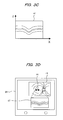
- FIG. 3A through FIG. 3D are schematic views used to describe the image information obtained via the two-dimensional image-capturing element 25 and the image information obtained via the OCT detecting element 39 in the configuration of FIG. 1 as described above.
- the horizontal axis (X axis) corresponds to the horizontal direction of the imaging surface of the two-dimensional image-capturing element 25, and the vertical axis (Y axis) corresponds to the orthogonal direction of the imaging surface.
- a slit image 43 at a predetermined moment is taken on a dark background 44 on the imaging surface of the image-capturing element 25 by the action of the optical system described above.
- This slit image 43 moves periodically over time in the direction of the X axis (the direction of arrow 43a) in FIG. 3a in accordance with the scanning performed by the light scanning means (galvano mirror 10a) and the re-scanning means (galvano mirror 10a).
- image information obtained via the image-capturing element 25 is subjected to various types of signal processing in the signal processing circuit 26, and, as shown in FIG. 3B , a two-dimensional reflection image 45 (when the optical filter 22 is removed from the optical path) or a fluorescent image (when the optical filter 22 is inserted into the optical path) of the object to be observed (e.g., the ocular fundus 15b of the eye to be examined) is obtained.
- the reflection (or fluorescent) image 45 is composed of high-contrast video information in which stray light and unwanted scattered light is eliminated from the detection light by the action of the detection aperture (slit 18) in the optical system.
- FIG. 3B schematically shows a blood vessel pattern 45a in the ocular fundus being imaged. In this drawing, the portion in which tomographic image is to be obtained using the OCT measuring means is indicated schematically by arrow 46.
- the portion 46 in which the tomographic image is to be obtained is designated using input means (not shown) such as an input pen or mouse connected to the PC 27.
- input means such as an input pen or mouse connected to the PC 27.
- the coordinate positions of the designated portion are stored in the memory of the PC 27.
- the start measurement button (not shown) displayed on the screen of the display device 28 is clicked to start the measurement performed by the OCT measuring means.
- the output signals from the detecting element 39 are subjected to predetermined signal processing such as filter processing via the signal processing device 40, and then sent to the PC 27.
- the PC 27 uses a calculation method for spectral domain OCT such as fast Fourier transform (FFT) to determine the depth (Z) information at each coordinate position (X) corresponding to the measurement range designated by the input means, and obtains a tomographic image (XZ image) in the depth direction.
- FFT fast Fourier transform
- FIG. 3C schematically shows the tomographic image 47 in the depth direction (XZ image) obtained using the OCT measuring means.
- This shows image information obtained via the optical fiber interferometer 32 and the detecting element 39.
- the tomographic image 47 in the depth direction (XZ image) of the object to be observed can be detected using OCT image information.
- FIG. 3D schematically shows the simultaneous display on the monitor screen of the display device 28 with respect to the reflection image 45 (or fluorescent image) obtained via the two-dimensional image-capturing element 25 and the tomographic image 47 (XZ image) obtained via the OCT detecting element 39.
- information obtained from the simultaneous detection of a reflection image (or fluorescent image) and a tomographic image of an ocular fundus can be effectively utilized in precise diagnoses and surgical planning for serious eye diseases such as various types of retinal degeneration and retinal detachment.
- FIG. 2 shows a system configuration of the embodiment of the present invention that differs from the embodiment in FIG. 1 .
- the object to be observed is also assumed to be a human eyeball (anterior ocular segment or ocular fundus).
- the elements identical to the structural elements in FIG. 1 are denoted by the same reference numerals.
- the structural elements denoted by the same reference numerals in FIG. 2 have the same configuration and function as those in FIG. 1 . The following is primarily a description of the points of difference with FIG. 1 .
- Light beams from the light sources (SLD or LD) 1, 2 for observing a reflection image or fluorescent image pass through the dichroic mirror 6 and the like, and are shaped by the cylindrical lens 7 into a line beam (slit-shaped beam) which is linear at the focal position.
- the light beam shaped into a slit is reflected by the beam splitter 9 (BS, optical path splitting member), and then scanned one-dimensionally by the galvano mirror 10a.
- the scanned light beam is incident on the eye to be examined 15 (anterior ocular segment 15a or ocular fundus 15b) via a mirror 41, dichroic mirror 11, lenses 12, 13, and objective lens 14.
- the lenses 12, 13 and the objective lens 14 constitute a telecentric optical system, and the conjugate relationship between the galvano mirror 10a and the anterior ocular segment 15a of the eye to be examined is assumed to be kept substantially constant.
- the reflected light from the predetermined portion of the eye to be examined goes back along the optical path described above, is transmitted through the BS 9, and then passes through the detection aperture (slit) 18 via the lens 17.
- the detection aperture 18 removes the unwanted noise related to the detection light to improve the SN of the detection signals, and improves the contrast and gradation characteristics of the signals.
- the light beam that has passed through the detection aperture is guided via the lens 21 and the optical filter 22 to a galvano mirror 42a mounted on a galvanometer 42.
- the optical filter 22 is inserted into the optical path in order to detect a fluorescent image based on naturally occurring fluorescent light or to detect a fluorescent image when a fluorescent imaging agent is used.
- the optical filter 22 is removed from the optical path when a reflection image is to be obtained instead of a fluorescent image.
- the galvano mirror 42a (second light scanning means) is the re-scanning means for scanning the detection light in the same scanning direction as the galvano mirror 10a (first light scanning means).
- the scanning frequency is set at the same level for both galvano mirrors 42a, 10a.
- the detection light re-scanned by the galvano mirror 42a is focused on the two-dimensional image-capturing element 25 such as a CCD via the mirror 23 and the lens 24.
- the frame rate of the two-dimensional image-capturing element 25 is 60 frames per second
- the scanning frequency of the galvano mirrors 10a, 42a is 60 Hz.
- two galvano mirrors are used.
- the deflecting-back mirrors (16, 19, 20) needed in the configuration of FIG. 1 are not required, and the efficiency of the detection optical system can be improved. Because the configuration of the optical path is simple, optical adjustment is advantageously facilitated as well.
- the video signals outputted from the image-capturing element 25 are subjected to predetermined signal processing via the signal processing circuit 26 to extract video signals (for a reflection image, fluorescent image, or the like).
- the obtained video signals are displayed via the PC 27 on the display means 28 such as a liquid crystal monitor, and can be stored in a storage device (not shown) if necessary.
- the PC 27 is used to control the image signals and simultaneously controls the overall operation of the optical system (particularly the galvano meters 10 and 42, and the like).
- OCT measuring means using an optical fiber interferometer (shown by the dashed lines in a configuration similar to that shown in FIG. 1 ) is detachably added to the relay optical path between the objective optical system (14) and the light scanning means (10a).
- reference numeral 29 denotes a high-luminance light-emitting diode (super luminescent diode or SLD) emitting partially coherent light. This is the light source required for observation of a tomographic image.
- the light beam from the SLD light source 29 is guided to the optical fiber interferometer 32 via the lens 30.
- the optical fiber interferometer 32 has an optical path divided in four directions: a light source optical path 32a, a reference optical path 32b, a probe optical path 32c, and a detection optical path 32d.
- the optical path length of the reference optical path can be suitably adjusted if necessary using the moving stage 36.
- the light beam traveling through the probe optical path 32c exits from the coupler 31c, and is incident on the scanning unit 37 to perform light beam scanning.
- the OCT light beam scanned by the scanning unit 37 is reflected by the dichroic mirror 11, and is then incident on the eye to be examined 15, which is the object to be observed, via the lenses 12, 13, and the objective lens 14.
- the reflected light from the eye to be examined traces back through the optical system described above (objective lens 14, lenses 13 and 12, dichroic mirror 11), and is guided to the optical fiber 32c via the scanning unit 37.
- the probe light that has passed through the optical fiber serving as the probe optical path 32c is combined with the reference light through the reference optical path 32b. This causes interference light (detection light) to be generated on the side of the detection optical path 32d.
- the detection light emitted from the optical fiber undergoes spectral processing by the spectrometer 38, detected by the one-dimensional CCD line sensor (OCT detecting element) 39, and outputted as electric signals.
- the output signals from the CCD line sensor 39 are sent via the signal processing device 40 to the personal computer (PC) 27.
- a predetermined software inside the PC carries out predetermined arithmetic processing such as a fast Fourier transform (FFT) required for a spectral domain OCT method, and then calculates the tomographic image information of the eye to be examined 15. The final results are displayed on the monitor screen of the display device 28.
- FFT fast Fourier transform
- the slit image 43 is moved periodically over time in the direction of arrow 43a in accordance with scanning by the galvano mirror (scanning means) 10a and the galvano mirror (re-scanning means) 42a.
- a two-dimensional reflection image 45 or fluorescent image of the object to be observed (e.g., the ocular fundus 15b of an eye to be examined) is obtained via the image-capturing element 25, as shown in FIG. 3B .
- the portion 46 in which tomographic information is to be obtained is designated in the image using the input means.
- This allows a tomographic image 47 (XZ image) of the object to be observed (the ocular fundus 15b) to be obtained in the depth direction via the OCT measuring means, the signal processing device 40, and the PC 27.
- the reflection image 45 or fluorescent image
- they can be simultaneously displayed as measurement results on the monitor screen in the display device 28, as shown in FIG. 3D .
- information obtained from the simultaneous detection of a reflection image (or fluorescent image) and a tomographic image of an ocular fundus can be effectively utilized in precise diagnoses and surgical planning for serious eye diseases such as various types of retinal degeneration and retinal detachment. This is the same as in the embodiment in FIG. 1 .
Landscapes
- Health & Medical Sciences (AREA)
- Life Sciences & Earth Sciences (AREA)
- Physics & Mathematics (AREA)
- General Health & Medical Sciences (AREA)
- Ophthalmology & Optometry (AREA)
- Engineering & Computer Science (AREA)
- Biochemistry (AREA)
- Chemical & Material Sciences (AREA)
- General Physics & Mathematics (AREA)
- Immunology (AREA)
- Pathology (AREA)
- Nuclear Medicine, Radiotherapy & Molecular Imaging (AREA)
- Radiology & Medical Imaging (AREA)
- Biophysics (AREA)
- Optics & Photonics (AREA)
- Analytical Chemistry (AREA)
- Biomedical Technology (AREA)
- Heart & Thoracic Surgery (AREA)
- Medical Informatics (AREA)
- Molecular Biology (AREA)
- Surgery (AREA)
- Animal Behavior & Ethology (AREA)
- Public Health (AREA)
- Veterinary Medicine (AREA)
- Investigating Or Analysing Materials By Optical Means (AREA)
- Eye Examination Apparatus (AREA)
- Investigating, Analyzing Materials By Fluorescence Or Luminescence (AREA)
- Length Measuring Devices By Optical Means (AREA)
Abstract
Light beams from light sources 1, 2 are scanned by a galvano mirror 10a to illuminate a predetermined portion 15b of an object to be observed 15 via an objective lens 14. The reflected light from the object is re-scanned by the galvano mirror 10a to obtain a two-dimensional image via an image-capturing element 25. Measuring means composed of an OCT interferometer 32 is branched or coupled in the optical path between the objective lens 14 and the galvano mirror 10a to obtain a tomographic image of the object. In this configuration, the two-dimensional image and the tomographic image of the object can be displayed simultaneously on a display device 28.
Description
- The present invention relates to an optical image-capturing apparatus, and more specifically to an optical image-capturing apparatus in which a light beam from a light source is scanned to illuminate a predetermined portion of an object to be observed, and reflected light or fluorescent light from the object is received to obtain two-dimensional image information of the object.
- As is well known, optical image-capturing apparatuses using light beam scanning can observe high-contrast/high-resolution image information based on reflected light or fluorescent light from an object to be observed. As a result, they are particularly useful in the observation of low-contrast objects. Widely used examples include scanning laser microscopes (SLM) in biological and industrial fields and medical applications such as scanning laser ophthalmoscopes (SLO) in the field of ophthalmology.
- A technology related to SLM or SLO is, e.g., a scanning method using a slit beam, which reduces the burden associated with the high-speed operation of the light scanning means and which is both highly economical and practical because the object can be imaged in real time. The following is known of this technology.
-
Patent Document 1 discloses a configuration for an optical microscope in which a slit-shaped light beam is scanned by the first surface of a rotating mirror to illuminate an object to be observed, and reflected light from the object to be observed is scanned using the second and third surfaces of the rotating mirror and received by a predetermined detector array. -
Patent Document 2 discloses a configuration for a scanning ophthalmoscope in which a light beam shaped so as to converge linearly on the focal plane is scanned one-dimensionally to illuminate the ocular fundus of an eye to be examined, and reflected light from the ocular fundus is received via scanning means by a photodetector array corresponding to the convergence line of the light beam. - Patent Document 3 discloses a configuration for a scanning laser ophthalmoscope in which a light beam in the shape of a line is scanned one-dimensionally in the direction orthogonal to the direction of the line to illuminate an eye to be examined, and reflected light from the eye to be examined is received by a one-dimensional linear CCD array detector corresponding to the line direction of the light beam.
-
Patent Document 4 discloses a configuration for an ophthalmoscope in which a slit-shaped light beam is scanned by the first surface of a rotating mirror to illuminate the ocular fundus of an eye to be examined, and reflected light from the ocular fundus is scanned by the second and third surfaces of the rotating mirror and received by an array-type photodetector such as a predetermined CCD or CMOS sensor. - Non-Patent
Document 1 discloses a basic configuration of a scanning confocal microscope including a scanning optical system using the obverse side and reverse side of an oscillating mirror and detecting the specular reflection of a slit-shaped light beam. The ability of this configuration to observe clear corneal tissue cells in real time with high contrast has been demonstrated experimentally. - A device which combines the technology of SLMs and SLOs scanning optical systems with the technology of interference optical systems has recently garnered attention in the fields of medicine and biology. This device is an image-capturing apparatus for tomographic information (optical coherence tomography or OCT) that uses the interference phenomenon of low-interference light beams (partially coherent light). Many technologies related to OCT have been presented. The following are some examples.
- Patent Document 5 discloses an OCT configuration including an interferometer using a light source having short coherence length characteristics and an optical fiber, horizontal scanning means arranged in the optical path of probe light directed towards a sample material, and the like. The basic technology for generating a tomographic image of the sample material is disclosed in this patent document.
- Patent Document 6 discloses a configuration in which the light beam is split into a reference arm and a measurement arm, and a spectroscope detects the intensity of light that appears as interference between measurement light via the measurement arm and reference light via the reference arm. This patent document discloses a configuration in which an arithmetic operation such as a Fourier transform is performed on detected signals obtained via the spectroscope to thereby allow optical tomography of transparent, partially transparent, and opaque objects.
- Patent Document 7 discloses a measurement device composed of an interferometer and a spectrometer wherein the light beam from a light source is condensed linearly relative to an object to be measured, and observed light from the object to be measured is detected via the spectrometer by a two-dimensional image sensor. An arithmetic operation such as a Fourier transform is performed on the detected signals from the image sensor, and tomographic information on the object to be measured is obtained at high speed in accordance with the computational speed.
- Patent Document 8 proposes an OCT configuration including an interferometer, light modulating means, light scanning means, re-scanning means, and two-dimensional image-capturing means. In this configuration, it is shown that reflection intensity information from the interior of an object can be obtained at high speed by properly processing the interference information detected from the output signals of the image-capturing means.
- Non-Patent
Document 2 discloses a configuration for a device combining a line scanning laser ophthalmoscope (LSLO) using a one-dimensional CCD array sensor as a detector and a spectral domain OCT (SDOCT) using an optical fiber interferometer. In this configuration, it is empirically shown that two-dimensional reflection images or tomographic images in the depth direction of the ocular fundus to be observed can be selectively imaged using a single device. -
- Patent Document 1:
U.S. Patent No. 4,241,257 - Patent Document 2:
U.S. Patent No. 4,768,874 - Patent Document 3:
U.S. Patent No. 6,758,564 - Patent Document 4:
U.S. Patent No. 7,331,669 - Patent Document 5: PCT
(WO) 6-511312 3479069 - Patent Document 6: Japanese Laid-open Patent Publication No.
11-325849 - Patent Document 7: Japanese Laid-open Patent Publication No.
2006-116028 - Patent Document 8: Japanese Laid-open Patent Publication No.
2008-309613 -
- Non-Patent Document 1: Article, Applied Optics, Vol. 33 (1994); No. 4, pp. 695-701, "Real-time scanning slit confocal microscopy of the in vivo human cornea" (B.R. Masters and A.A. Thaer)
- Non-Patent Document 2: Article, Optics Express, Vol. 14 (2006), No. 26, pp. 12909-12914, "Hybrid retinal imager using line scanning laser ophthalmoscopy and spectral domain optical coherence tomography", (N.V. Iftimia, D.X. Hammer, C.E. Bigelow, T. Ustun, J.F. de Boer, and R.D. Ferguson)
- With the configuration disclosed in
Patent Document 1 andPatent Document 4, it is possible to expect efficient light detection and high-contrast image observation using the specular reflection characteristics of the sample material. However, since three sides of a multifaceted mirror are used as the scanning means, there are significant constraints on the optical design with respect to the arrangement of components. Also, since the pupil of the objective lens is split for light projection and light detection, the optical resolution characteristics are disadvantageously restricted. - With the configuration disclosed in
Patent Document 2 and Patent Document 3, one can expect a very simple confocal optical system with a single scanning means. However, since a one-dimensional line sensor is used as the detector, the choice of detectors is very limited, and since there are few high-sensitivity detectors, the configuration is not suitable for imaging at low light intensity. - With the configuration disclosed in Non-Patent
Document 1, a relatively simple system configuration can be realized by the scanning optical system using the obverse side and reverse side of an oscillating mirror. However, since the reflective surface of the oscillating mirror and the pupil plane of the objective lens are divided in two for light projection and light detection, there are big design constraints, and optical resolution characteristics disadvantageously undergo restriction. - The configuration disclosed in Patent Document 5 reveals the basic technical details of an OCT using an optical fiber interferometer. However, in the configuration disclosed in this document, the scanning means and signal processing system have a slow speed, and, disadvantageously, high-contrast reflection images or fluorescent images as in SLM or SLO cannot be realized in real time.
- The configuration disclosed in Patent Document 6 and Patent Document 7 reveals a spectral domain OCT method using a spectrometer in the detection system. This method can advantageously be used to obtain tomographic information at high speed without performing mechanical scanning in the depth direction. However, in the configuration disclosed in these documents, the presence of a reference optical path and a spectrometer disadvantageously render the method unsuitable for dedicated use in high-sensitivity SLM or SLO.
- In the configuration disclosed in Patent Document 8, a novel OCT method has been proposed in which scanning means and light modulating means are used efficiently. However, in the configuration disclosed in this document, the presence of a reference optical path and moving means in the direction of the optical axis disadvantageously render the method unsuitable for dedicated use in high-sensitivity SLM or SLO.
- In the configuration disclosed in
Non-Patent Document 2, a novel optical system combining SLO and OCT has been realized. However, in the configuration disclosed in this document, since a one-dimensional line sensor is used as the detector, the choice of detectors is limited and high-sensitivity imaging is disadvantageously difficult, as are similar to those of the configurations disclosed inPatent Document 2 and Patent Document 3. Also, since the detector is shared by the SLO and OCT systems, the configuration of the members related to the branch in the optical path is complicated, and there are disadvantageously significant optical design constraints. - Therefore, the present invention has been proposed to solve the aforementioned problems, and provides a very practical optical image-capturing apparatus which has fewer design constraints and better optical characteristics than the methods of the prior art, and which, without using no special detectors or optical components, can be used as a dedicated device for SLM or SLO being capable of obtaining high-sensitivity, high-contrast images in real time, and being capable of additionally realizing even OCT measurement functions, if necessary.
- The present invention (claims 1 through 4) relates to an optical image-capturing apparatus in which a light beam from a light source is scanned to illuminate a predetermined portion of an object to be observed, and reflected light or fluorescent light from the object is received to obtain two-dimensional image information of the object.
- The invention in
claim 1 is characterized by the apparatus comprising: - a first light source for emitting a light beam;
- optical reshaping means for transforming the light beam from the first light source into a slit shape;
- an optical path splitting member for introducing the light beam via the optical reshaping means into an optical path towards the object to be observed;
- light scanning means for one-dimensionally scanning at a predetermined frequency the light beam introduced via the optical path splitting member;
- an objective optical system for guiding the light beam scanned by the light scanning means to the object to be observed and for guiding the reflected light or fluorescent light from the object to be observed;
- a light-receiving optical system in which the reflected light or fluorescent light from the object to be observed via the objective optical system is guided through the light scanning means and the optical path splitting member and then through a predetermined detection aperture;
- re-scanning means for scanning detection light via the light-receiving optical system at the same scanning frequency and in the same scanning direction as the light scanning means;
- two-dimensional image-capturing means for detecting the detection light via the re-scanning means at a frame rate corresponding to a scanning frequency of the light scanning means and the re-scanning means; and
- measuring means branched or coupled in a relay optical path between the objective optical system and the light scanning means, provided with a second light source for emitting a light beam having a wavelength different from that of the first light source, and adapted for obtaining, based on the light beam from the second light source, predetermined image information in a direction different from that of the output information from the two-dimensional image-capturing means.
- The invention in
claim 2 is characterized in that, in the invention inclaim 1, the measuring means is detachably constituted in the relay optical path relative to other optical system elements. - The invention in claim 3 is characterized by the apparatus comprising:
- a first light source for emitting a light beam;
- optical reshaping means for transforming the light beam from the first light source into a slit shape;
- an optical path splitting member for introducing the light beam via the optical reshaping means into an optical path towards the object to be observed;
- light scanning means for one-dimensionally scanning at a predetermined frequency the light beam introduced via the optical path splitting member;
- an objective optical system for guiding the light beam scanned by the light scanning means to the object to be observed and for guiding the reflected light or fluorescent light from the object to be observed;
- a recursive optical system in which the reflected light or fluorescent light from the object to be observed via the objective optical system is guided through the light scanning means and the optical path splitting member and then through a predetermined detection aperture, and is then guided to the light scanning means;
- two-dimensional image-capturing means for detecting the detection light via the recursive optical system at a frame rate corresponding to a scanning frequency of the light scanning means; and
- measuring means branched or coupled in a relay optical path between the objective optical system and the light scanning means, provided with a second light source for emitting a light beam having a wavelength different from that of the first light source, and adapted for obtaining, based on the light beam from the second light source, predetermined image information in a direction different from that of the output information from the two-dimensional image-capturing means.
- The invention in
claim 4 is characterized by the apparatus comprising: - a first light source for emitting a light beam;
- optical reshaping means for transforming the light beam from the first light source into a slit shape;
- an optical path splitting member for introducing the light beam via the optical reshaping means into an optical path towards the object to be observed;
- first light scanning means for one-dimensionally scanning at a predetermined frequency the light beam introduced via the optical path splitting member;
- an objective optical system for guiding the light beam scanned by the light scanning means to the object to be observed and for guiding the reflected light or fluorescent light from the object to be observed;
- a light.-receiving optical system in which the reflected light or fluorescent light from the object to be observed via the objective optical system is guided through the light scanning means and the optical path splitting member and then through a predetermined detection aperture;
- second light scanning means for scanning detection light via the light-receiving optical system at the same scanning frequency and in the same scanning direction as the first light scanning means;
- two-dimensional image-capturing means for detecting the detection light via the second light scanning means at a frame rate corresponding to a scanning frequency of the first and second light scanning means; and
- measuring means branched or coupled in a relay optical path between the objective optical system and the first light scanning means, provided with a second light source for emitting a light beam having a wavelength different from that of the first light source, and adapted for obtaining, based on the light beam from the second light source, predetermined image information in a direction different from that of the output information from the two-dimensional image-capturing means.
- In the configuration of the present invention, two-dimensional image-capturing means has been employed as the detector, and low-speed scanning means and low-speed re-scanning means are used which operate at the frame rate of the image-capturing means. Therefore, the scanning confocal optical system can be simplified, and the electrical controls are also simple.
- Since the projected light beam and the received light beam are coaxial in the optical system as the apparatus dedicated for SLMs or SLOs, two-dimensional reflection images (or fluorescent images) with high resolution, sensitivity, contrast, and gradation properties can be obtained at high speeds corresponding to the frame rate of the image-capturing element.
- If necessary, a measurement function using an OCT interferometer system can be added. This allows multifunctionality, such as the ability to obtain tomographic image information in the depth direction while obtaining a two-dimensional reflection image (or fluorescent image) of the object.
- If a two-dimensional image-capturing element is modified to be more precise, more sensitive, or faster in the future, SLMs and SLOs functions can be improved by simply upgrading the apparatus. In other words, a very practical and economical optical image-capturing apparatus can be realized.
-
-
FIG. 1 is a view showing a configuration of the first embodiment of an optical image-capturing apparatus according to the present invention; -
FIG. 2 is a view showing a configuration of the second embodiment of an optical image-capturing apparatus according to the present invention; -
FIG. 3A is an illustrative view showing a process for obtaining image information that is detected and displayed by the optical image-capturing apparatus of the present invention; -
FIG. 3B is an illustrative view showing a tomographic image detected by the optical image-capturing apparatus of the present invention; -
FIG. 3C is an illustrative view showing a reflection image detected by the optical image-capturing apparatus of the present invention; and -
FIG. 3D is an illustrative view showing a tomographic image and a reflection image detected by the optical image-capturing apparatus of the present invention. - In the following, the present invention will be described in detail based on embodiments shown in the drawings. In the embodiments shown in the following, an object to be observed is exemplified as an ocular fundus of a human eye, and the embodiments of optical systems are shown which are suitable for performing eye examinations. However, the present invention is not limited to these embodiments, and the objects to be observed may also include other biological tissues or living organism samples such as skin with strong light scattering properties.
- In
FIG. 1 ,reference numerals Light sources light sources lenses 3, 4, and combined on the same optical axis via a mirror 5 and a dichroic mirror 6. - The light beam via the mirror 5 and the dichroic mirror 6 is transformed into a flat line beam (a light beam focused linearly on the focal plane) via a cylindrical lens 7, is reflected by a mirror 8, and is made incident on a beam splitter (BS) 9. In other words, the cylindrical lens 7 plays the role of optical reshaping means for transforming the optical beam from the light source into a slit shape. The beam splitter 9 constitutes an optical path splitting member. It can be, for example, a beam splitter having uniform reflection versus transmission characteristics across the entire glass surface, or it can be a partially reflective mirror having characteristics which are reflective in the center and transmissive on the periphery. In the following description, the beam splitter 9 is described as optical path splitting member.
- The line beam reflected by the beam splitter 9 is incident on a mirror (galvano mirror) 10a mounted on a
galvanometer 10. Thegalvano mirror 10a performs one-dimensional scanning of the light beam in the direction orthogonal to the optical axis. The scanning by thegalvano mirror 10a is performed at a scanning frequency identical to the frame frequency of a typical television camera, for example, 30 Hz (or 60 Hz or another frequency). - The light beam scanned by the
galvano mirror 10a is incident on an eye to be examined 15 (anteriorocular segment 15a andocular fundus 15b) which is an object to be observed, via adichroic mirror 11,lenses lenses lenses lenses objective lens 14 constitute a telecentric optical system, which is constituted so that the conjugate relationship between thegalvano mirror 10a and the eye to be examined (anteriorocular segment 15a) is kept substantially constant. - The light beam incident on the eye to be examined 15 is focused linearly, for example, at a predetermined position of the
ocular fundus 15b. The operation of thegalvano mirror 10a (light scanning means) causes the focused line beam to be scanned on theocular fundus 15b one-dimensionally in the direction (X axis direction) orthogonal to the direction of the beam line (Y axis direction or the direction perpendicular to the plane of the paper inFIG. 1 ). This allows theocular fundus 15b of the eye to be examined to be probed two-dimensionally. - The reflected light from the eye to be examined travels back through the above-mentioned optical system, i.e., through the
objective lens 14,lenses dichroic mirror 11, and thegalvano mirror 10a, and reaches the beam splitter 9 (optical path splitting member). The light beam transmitted through the beam splitter 9 is the detection light, which passes through a detection aperture (slit) 18 via amirror 16 and alens 17, and is incident on and reflected by the mirror surface on the reverse side of thegalvano mirror 10a viamirrors lens 21, and anoptical filter 22. - The
optical filter 22 is inserted to detect fluorescent light from theocular fundus 15b of the eye to be examined. The filter is suitably inserted when needed, as indicated by the arrow inFIG. 1 , for example, when naturally occurring fluorescent light from the ocular fundus is detected, or when a fluorescent imaging agent such as sodium fluorescein or ICG (indocyanine green) is used. The detection light via thegalvano mirror 10a is reflected by amirror 23, and projected by alens 24 onto the imaging surface of a two-dimensional image-capturing element (two-dimensional image-capturing means such as a CCD camera) 25. - In this optical system, the
slit 18 has its gap (slit width) restricted in the scanning direction of thegalvano mirror 10a. This eliminates noise caused by unwanted stray light and scattered light, and improves the signal-to-noise (SN) characteristics of the detection light. This also reduces the level of background light, efficiently improving the contrast and gradation characteristics of the signal components with respect to video signals from the image-capturing element. Thegalvano mirror 10a simultaneously serves as the scanning means for scanning the light beam from the light source owing to the reflection action on the obverse side, and also serves as re-scanning means being capable of re-scanning the line beam passing through theslit 18 owing to the reflection action of the reverse side to perform two-dimensional imaging on the imaging surface of the image-capturingelement 25. - In other words, the
mirror 16, thelens 17, theslit 18, themirrors lens 21 form a recursive optical system that guides the detection light that is once guided via the galvano mirror (light scanning means) 10a and the beam splitter 9 again via the galvano mirror (re-scanning means) 10a to the two-dimensional imaging surface of the image-capturingelement 25. In the embodiment as shown inFIG. 1 , thegalvano mirror 10a is, owing to the reflection action of the obverse surface and reverse surface thereof, regarded as serving as the light scanning means for the projection beam and also serving as the re-scanning means for the detection light. - Next, the output signals from the two-dimensional image-capturing
element 25 are sent to asignal processing circuit 26 to perform various types of signal processing related to video signals. Thesignal processing circuit 26 includes a plurality of electronic circuits for performing signal processing using both analog and digital technologies, such as predetermined amplifier circuits, clamp circuits, buffer circuits, analog-to-digital converters, and various digital signal processing circuits. The processed and generated output signals are then sent to a computer (personal computer or PC) 27. - The
PC 27 controls the overall operation of the optical systems (especially thegalvanometer 10 and the like), and it also performs controls in which the video signals obtained via the two-dimensional image-capturingelement 25 and thesignal processing circuit 26 is outputted and displayed on adisplay device 28 such as a liquid crystal television monitor, and transferred to a predetermined storage device (not shown) for storage, as required. - In the embodiment In
FIG. 1 , in addition to the optical imaging system described above, measuring means that use an optical fiber interferometer for optical coherence tomography (OCT) (the portion defined by the dashed lines inFIG. 1 ) is detachably installed in a relay optical path between the objective optical system (14) and the light scanning means (10a). - The
reference numeral 29 inFIG. 1 denotes a high-luminance light-emitting diode (super luminescent diode or SLD) that emits partially coherent light. This is the light source (second light source) with the low interference characteristics required for observation of a tomographic image. Thelight source 29 can be an SLD light source having physical characteristics such as a central wavelength (e.g., 850 nm) different from the central wavelengths of thelight sources light source 29 is collimated by alens 30, and then coupled via acoupler 31a to anoptical fiber interferometer 32. Theoptical fiber interferometer 32 has an optical path divided in four directions: a light sourceoptical path 32a, a referenceoptical path 32b, a probeoptical path 32c, and a detectionoptical path 32d. Theseoptical paths 32a-32d are composed of optical fibers. - The light beam traveling through the reference
optical path 32b exits from acoupler 31b, and undergoes intensity adjustment by anND filter 33. The light beam is then reflected by amirror 34 and goes back to the referenceoptical path 32b. Themirror 34 is mounted on a piezoelectric element (piezoelectric transducer) 35, which subtly vibrates themirror 34 at a predetermined frequency in the direction of the optical axis to perform a periodic phase shift for the light beam. The optical path length of the referenceoptical path 32b has to be equal to the optical path length of the probeoptical path 32c including an optical path towards the eye to be examined. Thereflective mirror 34 is accordingly secured on top of a movingstage 36 via thepiezoelectric element 35 and is appropriately adjusted if necessary. - On the other hand, the light beam traveling through the probe
optical path 32c exits from acoupler 31c, and is incident on ascanning unit 37 including a predetermined galvanometer to perform light beam scanning. Thescanning unit 37 includes two galvanometers (not shown), and can perform a desired light beam scanning (linear scanning, circular scanning, and the like) in a direction orthogonal to the optical axis (XY planar direction). - The OCT light beam scanned by the
scanning unit 37 is reflected by thedichroic mirror 11, passes through thelenses objective lens 14, and is then incident on the eye to be examined 15 (anteriorocular segment 15a orocular fundus 15b), i.e., the object to be observed. As described earlier, thelenses objective lens 14 constitute a telecentric optical system, thereby allowing a configuration in which the conjugate relationship between the scanningunit 37 and the anteriorocular segment 15a of the eye to be examined is kept substantially constant. - Referring to the OCT light beam, the reflected light from the eye to be examined traces back through the optical system described above (
objective lens 14,lenses scanning unit 37 and thecoupler 31c to the optical fiber. The probe light moving through the probeoptical path 32c of the optical fiber is combined with the reference light through the referenceoptical path 32b. This causes interference light (detection light) to be generated on the side of the detectionoptical path 32d. The detection light emitted from the optical fiber of the detectionoptical path 32d passes through thecoupler 31d und undergoes spectral processing by aspectrometer 38. The detection light is then detected by a one-dimensional CCD line sensor (OCT detecting element) 39, and outputted as electric signals. - The output signals from the
CCD line sensor 39 undergo predetermined signal processing such as filter processing via asignal processing device 40, and are then sent to thePC 27. A predetermined software inside the PC carries out predetermined arithmetic processing such as a fast Fourier transform (FFT) required for a spectral domain OCT method, and then calculates tomographic image information from the object to be observed (the eye to be examined). The final results are displayed on the monitor screen of adisplay device 28 such as a liquid crystal monitor. -
FIG. 3A through FIG. 3D are schematic views used to describe the image information obtained via the two-dimensional image-capturingelement 25 and the image information obtained via theOCT detecting element 39 in the configuration ofFIG. 1 as described above. - In
FIG. 3A , the horizontal axis (X axis) corresponds to the horizontal direction of the imaging surface of the two-dimensional image-capturingelement 25, and the vertical axis (Y axis) corresponds to the orthogonal direction of the imaging surface. Aslit image 43 at a predetermined moment is taken on adark background 44 on the imaging surface of the image-capturingelement 25 by the action of the optical system described above. Thisslit image 43 moves periodically over time in the direction of the X axis (the direction ofarrow 43a) inFIG. 3a in accordance with the scanning performed by the light scanning means (galvano mirror 10a) and the re-scanning means (galvano mirror 10a). - Accordingly, image information obtained via the image-capturing
element 25 is subjected to various types of signal processing in thesignal processing circuit 26, and, as shown inFIG. 3B , a two-dimensional reflection image 45 (when theoptical filter 22 is removed from the optical path) or a fluorescent image (when theoptical filter 22 is inserted into the optical path) of the object to be observed (e.g., theocular fundus 15b of the eye to be examined) is obtained. As mentioned above, the reflection (or fluorescent)image 45 is composed of high-contrast video information in which stray light and unwanted scattered light is eliminated from the detection light by the action of the detection aperture (slit 18) in the optical system.FIG. 3B schematically shows ablood vessel pattern 45a in the ocular fundus being imaged. In this drawing, the portion in which tomographic image is to be obtained using the OCT measuring means is indicated schematically byarrow 46. - While viewing the
reflection image 45 displayed on thedisplay device 28, theportion 46 in which the tomographic image is to be obtained is designated using input means (not shown) such as an input pen or mouse connected to thePC 27. The coordinate positions of the designated portion (the source and destination in the XY coordinates, or the like) are stored in the memory of thePC 27. The start measurement button (not shown) displayed on the screen of thedisplay device 28 is clicked to start the measurement performed by the OCT measuring means. The output signals from the detectingelement 39 are subjected to predetermined signal processing such as filter processing via thesignal processing device 40, and then sent to thePC 27. ThePC 27 uses a calculation method for spectral domain OCT such as fast Fourier transform (FFT) to determine the depth (Z) information at each coordinate position (X) corresponding to the measurement range designated by the input means, and obtains a tomographic image (XZ image) in the depth direction. -
FIG. 3C schematically shows thetomographic image 47 in the depth direction (XZ image) obtained using the OCT measuring means. This shows image information obtained via theoptical fiber interferometer 32 and the detectingelement 39. In other words, thetomographic image 47 in the depth direction (XZ image) of the object to be observed (theocular fundus 15b) can be detected using OCT image information. -
FIG. 3D schematically shows the simultaneous display on the monitor screen of thedisplay device 28 with respect to the reflection image 45 (or fluorescent image) obtained via the two-dimensional image-capturingelement 25 and the tomographic image 47 (XZ image) obtained via theOCT detecting element 39. - As an example of important applications of OCT in clinical medicine, information obtained from the simultaneous detection of a reflection image (or fluorescent image) and a tomographic image of an ocular fundus can be effectively utilized in precise diagnoses and surgical planning for serious eye diseases such as various types of retinal degeneration and retinal detachment.
-
FIG. 2 shows a system configuration of the embodiment of the present invention that differs from the embodiment inFIG. 1 . InFIG. 2 , the object to be observed is also assumed to be a human eyeball (anterior ocular segment or ocular fundus). InFIG. 2 , the elements identical to the structural elements inFIG. 1 are denoted by the same reference numerals. The structural elements denoted by the same reference numerals inFIG. 2 have the same configuration and function as those inFIG. 1 . The following is primarily a description of the points of difference withFIG. 1 . - Light beams from the light sources (SLD or LD) 1, 2 for observing a reflection image or fluorescent image pass through the dichroic mirror 6 and the like, and are shaped by the cylindrical lens 7 into a line beam (slit-shaped beam) which is linear at the focal position. The light beam shaped into a slit is reflected by the beam splitter 9 (BS, optical path splitting member), and then scanned one-dimensionally by the
galvano mirror 10a. - The scanned light beam is incident on the eye to be examined 15 (anterior
ocular segment 15a orocular fundus 15b) via amirror 41,dichroic mirror 11,lenses objective lens 14. Here, thelenses objective lens 14 constitute a telecentric optical system, and the conjugate relationship between thegalvano mirror 10a and the anteriorocular segment 15a of the eye to be examined is assumed to be kept substantially constant. - The reflected light from the predetermined portion of the eye to be examined (e.g., the
ocular fundus 15b) goes back along the optical path described above, is transmitted through the BS 9, and then passes through the detection aperture (slit) 18 via thelens 17. Thedetection aperture 18 removes the unwanted noise related to the detection light to improve the SN of the detection signals, and improves the contrast and gradation characteristics of the signals. The light beam that has passed through the detection aperture is guided via thelens 21 and theoptical filter 22 to agalvano mirror 42a mounted on agalvanometer 42. Theoptical filter 22 is inserted into the optical path in order to detect a fluorescent image based on naturally occurring fluorescent light or to detect a fluorescent image when a fluorescent imaging agent is used. Theoptical filter 22 is removed from the optical path when a reflection image is to be obtained instead of a fluorescent image. - The
galvano mirror 42a (second light scanning means) is the re-scanning means for scanning the detection light in the same scanning direction as thegalvano mirror 10a (first light scanning means). The scanning frequency is set at the same level for both galvano mirrors 42a, 10a. The detection light re-scanned by thegalvano mirror 42a is focused on the two-dimensional image-capturingelement 25 such as a CCD via themirror 23 and thelens 24. In the configuration shown inFIG. 2 , the frame rate of the two-dimensional image-capturingelement 25 is 60 frames per second, and the scanning frequency of the galvano mirrors 10a, 42a is 60 Hz. In this configuration, as a result, two galvano mirrors are used. The deflecting-back mirrors (16, 19, 20) needed in the configuration ofFIG. 1 are not required, and the efficiency of the detection optical system can be improved. Because the configuration of the optical path is simple, optical adjustment is advantageously facilitated as well. - The video signals outputted from the image-capturing
element 25 are subjected to predetermined signal processing via thesignal processing circuit 26 to extract video signals (for a reflection image, fluorescent image, or the like). The obtained video signals are displayed via thePC 27 on the display means 28 such as a liquid crystal monitor, and can be stored in a storage device (not shown) if necessary. ThePC 27 is used to control the image signals and simultaneously controls the overall operation of the optical system (particularly thegalvano meters - In the embodiment in
FIG. 2 , in addition to the optical imaging system described above, OCT measuring means using an optical fiber interferometer (shown by the dashed lines in a configuration similar to that shown inFIG. 1 ) is detachably added to the relay optical path between the objective optical system (14) and the light scanning means (10a). - In
FIG. 2 ,reference numeral 29 denotes a high-luminance light-emitting diode (super luminescent diode or SLD) emitting partially coherent light. This is the light source required for observation of a tomographic image. The light beam from the SLDlight source 29 is guided to theoptical fiber interferometer 32 via thelens 30. As described with reference toFIG. 1 , theoptical fiber interferometer 32 has an optical path divided in four directions: a light sourceoptical path 32a, a referenceoptical path 32b, a probeoptical path 32c, and a detectionoptical path 32d. - The light beam traveling through the reference
optical path 32b exits from thecoupler 31b, is then reflected by themirror 34, and goes back to the referenceoptical path 32b. The optical path length of the reference optical path can be suitably adjusted if necessary using the movingstage 36. - The light beam traveling through the probe
optical path 32c exits from thecoupler 31c, and is incident on thescanning unit 37 to perform light beam scanning. The OCT light beam scanned by thescanning unit 37 is reflected by thedichroic mirror 11, and is then incident on the eye to be examined 15, which is the object to be observed, via thelenses objective lens 14. - Referring to the OCT light beam, the reflected light from the eye to be examined traces back through the optical system described above (
objective lens 14,lenses optical fiber 32c via thescanning unit 37. The probe light that has passed through the optical fiber serving as the probeoptical path 32c is combined with the reference light through the referenceoptical path 32b. This causes interference light (detection light) to be generated on the side of the detectionoptical path 32d. The detection light emitted from the optical fiber undergoes spectral processing by thespectrometer 38, detected by the one-dimensional CCD line sensor (OCT detecting element) 39, and outputted as electric signals. - The output signals from the
CCD line sensor 39 are sent via thesignal processing device 40 to the personal computer (PC) 27. A predetermined software inside the PC carries out predetermined arithmetic processing such as a fast Fourier transform (FFT) required for a spectral domain OCT method, and then calculates the tomographic image information of the eye to be examined 15. The final results are displayed on the monitor screen of thedisplay device 28. - The same operations as those performed in the embodiment shown in
FIG. 1 are performed in the embodiment shown inFIG 2 . As shown inFIG. 3A , theslit image 43 is moved periodically over time in the direction ofarrow 43a in accordance with scanning by the galvano mirror (scanning means) 10a and the galvano mirror (re-scanning means) 42a. By virtue of the scanning, a two-dimensional reflection image 45 (or fluorescent image) of the object to be observed (e.g., theocular fundus 15b of an eye to be examined) is obtained via the image-capturingelement 25, as shown inFIG. 3B . - As described with reference to the embodiment in
FIG. 1 , theportion 46 in which tomographic information is to be obtained is designated in the image using the input means. This allows a tomographic image 47 (XZ image) of the object to be observed (theocular fundus 15b) to be obtained in the depth direction via the OCT measuring means, thesignal processing device 40, and thePC 27. In order to compare the reflection image 45 (or fluorescent image) with the tomographic image 47 (XZ image), they can be simultaneously displayed as measurement results on the monitor screen in thedisplay device 28, as shown inFIG. 3D . - As an example of important applications of OCT in clinical medicine, information obtained from the simultaneous detection of a reflection image (or fluorescent image) and a tomographic image of an ocular fundus can be effectively utilized in precise diagnoses and surgical planning for serious eye diseases such as various types of retinal degeneration and retinal detachment. This is the same as in the embodiment in
FIG. 1 . -
- 1 Imaging Light Source for Reflection Image (or Fluorescent Image)
- 7 Cylindrical Lens
- 9 Beam Splitter
- 10a, 42a Light Scanning Means or Re-scanning Means (Galvano Mirror)
- 11 Dichroic Mirror
- 15 Object to be observed (Eye to be examined)
- 18 Detection Aperture (Slit)
- 25 2-Dimensional Image-capturing Element
- 27 PC
- 28 Display Means
- 29 Light Source for OCT
- 32 Optical Fiber Interferometer
- 34 Reference Mirror
- 37 Scanning Unit
- 38 Spectrometer
- 39 Detecting Element for OCT
Claims (10)
- An optical image-capturing apparatus in which a light beam from a light source is scanned to illuminate a predetermined portion of an object to be observed, and reflected light or fluorescent light from the object is received to obtain two-dimensional image information of the object, comprising:a first light source for emitting a light beam;optical reshaping means for transforming the light beam from the first light source into a slit shape;an optical path splitting member for introducing the light beam via the optical reshaping means into an optical path towards the object to be observed;light scanning means for one-dimensionally scanning at a predetermined frequency the light beam introduced via the optical path splitting member;an objective optical system for guiding the light beam scanned by the light scanning means to the object to be observed and for guiding the reflected light or fluorescent light from the object to be observed;a light-receiving optical system in which the reflected light or fluorescent light from the object to be observed via the objective optical system is guided through the light scanning means and the optical path splitting member and then through a predetermined detection aperture;re-scanning means for scanning detection light via the light-receiving optical system at the same scanning frequency and in the same scanning direction as the light scanning means;two-dimensional image-capturing means for detecting the detection light via the re-scanning means at a frame rate corresponding to a scanning frequency of the light scanning means and the re-scanning means; andmeasuring means branched or coupled in a relay optical path between the objective optical system and the light scanning means, provided with a second light source for emitting a light beam having a wavelength different from that of the first light source, and adapted for obtaining, based on the light beam from the second light source, predetermined image information in a direction different from that of the output information from the two-dimensional image-capturing means.
- An optical image-capturing apparatus in which a light beam from a light source is scanned to illuminate a predetermined portion of an object to be observed, and reflected light or fluorescent light from the object is received to obtain two-dimensional image information of the object, comprising:a first light source for emitting a light beam;optical reshaping means for transforming the light beam from the first light source into a slit shape;an optical path splitting member for introducing the light beam via the optical reshaping means into an optical path towards the object to be observed;light scanning means for one-dimensionally scanning at a predetermined frequency the light beam introduced via the optical path splitting member;an objective optical system for guiding the light beam scanned by the light scanning means to the object to be observed and for guiding the reflected light or fluorescent light from the object to be observed;a light-receiving optical system in which the reflected light or fluorescent light from the object to be observed via the objective optical system is guided through the light scanning means and the optical path splitting member and then through a predetermined detection aperture;re-scanning means for scanning detection light via the light-receiving optical system at the same scanning frequency and in the same scanning direction as the light scanning means;two-dimensional image-capturing means for detecting the detection light via the re-scanning means at a frame rate corresponding to a scanning frequency of the light scanning means and the re-scanning means; andmeasuring means branched or coupled in a relay optical path between the objective optical system and the light scanning means, provided with a second light source for emitting a light beam having a wavelength different from that of the first light source, and adapted for obtaining, based on the light beam from the second light source, predetermined image information in a direction different from that of the output information from the two-dimensional image-capturing means,wherein the measuring means is detachably constituted in the relay optical path relative to other optical system elements.
- An optical image-capturing apparatus in which a light beam from a light source is scanned to illuminate a predetermined portion of an object to be observed, and reflected light or fluorescent light from the object is received to obtain two-dimensional image information of the object, comprising:a first light source for emitting a light beam;optical reshaping means for transforming the light beam from the first light source into a slit shape;an optical path splitting member for introducing the light beam via the optical reshaping means into an optical path towards the object to be observed;light scanning means for one-dimensionally scanning at a predetermined frequency the light beam introduced via the optical path splitting member;an objective optical system for guiding the light beam scanned by the light scanning means to the object to be observed and for guiding the reflected light or fluorescent light from the object to be observed;a recursive optical system in which the reflected light or fluorescent light from the object to be observed via the objective optical system is guided through the light scanning means and the optical path splitting member and then through a predetermined detection aperture, and is then guided to the light scanning means;two-dimensional image-capturing means for detecting the detection light via the recursive optical system at a frame rate corresponding to a scanning frequency of the light scanning means; andmeasuring means branched or coupled in a relay optical path between the objective optical system and the light scanning means, provided with a second light source for emitting a light beam having a wavelength different from that of the first light source, and adapted for obtaining, based on the light beam from the second light source, predetermined image information in a direction different from that of the output information from the two-dimensional image-capturing means.
- An optical image-capturing apparatus in which a light beam from a light source is scanned to illuminate a predetermined portion of an object to be observed, and reflected light or fluorescent light from the object is received to obtain two-dimensional image information of the object, comprising:a first light source for emitting a light beam;optical reshaping means for transforming the light beam from the first light source into a slit shape;an optical path splitting member for introducing the light beam via the optical reshaping means into an optical path towards the object to be observed;first light scanning means for one-dimensionally scanning at a predetermined frequency the light beam introduced via the optical path splitting member;an objective optical system for guiding the light beam scanned by the light scanning means to the object to be observed and for guiding the reflected light or fluorescent light from the object to be observed;a light-receiving optical system in which the reflected light or fluorescent light from the object to be observed via the objective optical system is guided through the light scanning means and the optical path splitting member and then through a predetermined detection aperture;second light scanning means for scanning detection light via the light-receiving optical system at the same scanning frequency and in the same scanning direction as the first light scanning means;two-dimensional image-capturing means for detecting the detection light via the second light scanning means at a frame rate corresponding to a scanning frequency of the first and second light scanning means; andmeasuring means branched or coupled in a relay optical path between the objective optical system and the first light scanning means, provided with a second light source for emitting a light beam having a wavelength different from that of the first light source, and adapted for obtaining, based on the light beam from the second light source, predetermined image information in a direction different from that of the output information from the two-dimensional image-capturing means.
- An optical image-capturing apparatus according to any one of claims 1 through 4, wherein focus-adjusting means is added to the optical path between the objective optical system and the light scanning means to change the focus position of the light beam in correspondence with the optical characteristics of the object to be observed.
- An optical image-capturing apparatus according to any one of claims 1 through 5, wherein the light beam illuminates the object to be observed as a slit-shaped light beam via the optical reshaping means, and the detection aperture is a slit-shaped aperture.
- An optical image-capturing apparatus according to any one of claims 1 through 6, wherein the light scanning means is composed of a reflective mirror mounted on a galvanometer, and the scanning direction of the light scanning means corresponds to the horizontal imaging direction of the two-dimensional image-capturing means.
- An optical image-capturing apparatus according to claim 7, wherein the re-scanning means uses the galvanometer in common with the light scanning means, and uses the reflective surface on the opposing side of the reflective mirror of the light scanning means to scan the detection light towards the two-dimensional image-capturing means.
- An optical image-capturing apparatus according to claim 7, wherein the re-scanning means uses a second galvanometer different from the galvanometer of the light scanning means and scans the detection light towards the two-dimensional image-capturing means by a reflective mirror mounted on the second galvanometer.
- An optical image-capturing apparatus according to any one of claims 1 through 9, wherein the measuring means is provided with light scanning means that is used solely for measurement and includes a predetermined galvanometer different from that of the light scanning means, and the light beam from the second light source can be scanned in a direction orthogonal to the optical axis direction of the relay optical path.
Applications Claiming Priority (2)
| Application Number | Priority Date | Filing Date | Title |
|---|---|---|---|
| JP2009019831A JP2010175448A (en) | 2009-01-30 | 2009-01-30 | Optical imaging device |
| PCT/JP2010/050584 WO2010087251A1 (en) | 2009-01-30 | 2010-01-20 | Optical image capturing device |
Publications (1)
| Publication Number | Publication Date |
|---|---|
| EP2392915A1 true EP2392915A1 (en) | 2011-12-07 |
Family
ID=42395512
Family Applications (1)
| Application Number | Title | Priority Date | Filing Date |
|---|---|---|---|
| EP10735720A Withdrawn EP2392915A1 (en) | 2009-01-30 | 2010-01-20 | Optical image capturing device |
Country Status (5)
| Country | Link |
|---|---|
| US (1) | US8238012B2 (en) |
| EP (1) | EP2392915A1 (en) |
| JP (1) | JP2010175448A (en) |
| CN (1) | CN102282456A (en) |
| WO (1) | WO2010087251A1 (en) |
Cited By (3)
| Publication number | Priority date | Publication date | Assignee | Title |
|---|---|---|---|---|
| EP2756796A1 (en) * | 2013-01-16 | 2014-07-23 | Canon Kabushiki Kaisha | Ophthalmic apparatus and ophthalmic method |
| WO2016192860A1 (en) * | 2015-06-04 | 2016-12-08 | Rascope Ag | Mobile apparatus for analyzing a surface area of an object using raman spectroscopy and fluorescence |
| IT201900016016A1 (en) | 2019-09-10 | 2021-03-10 | Centervue S P A | LINE SCANNING CONFOCAL TYPE INSPECTION APPARATUS. |
Families Citing this family (24)
| Publication number | Priority date | Publication date | Assignee | Title |
|---|---|---|---|---|
| US8117668B2 (en) * | 2006-04-27 | 2012-02-14 | Stephen James Crampton | Optical scanning probe |
| WO2011052248A1 (en) * | 2009-11-02 | 2011-05-05 | Olympus Corporation | Beam splitter apparatus, light source apparatus, and scanning observation apparatus |
| EP2621332B1 (en) * | 2010-09-28 | 2018-04-04 | SIFI MEDTECH S.r.l. | Corneal confocal microscope (ccm) |
| CN106264659B (en) | 2011-04-07 | 2019-02-22 | 3形状股份有限公司 | For guiding the 3D system and method for object |
| JP6039185B2 (en) * | 2012-01-20 | 2016-12-07 | キヤノン株式会社 | Imaging device |
| JP5936368B2 (en) * | 2012-01-20 | 2016-06-22 | キヤノン株式会社 | Optical coherence tomography apparatus and method for operating the same |
| JP2014115151A (en) * | 2012-12-07 | 2014-06-26 | Shimadzu Corp | Optical imaging device |
| CN103163111B (en) * | 2013-02-25 | 2015-11-04 | 天津大学 | A combined fluorescence mesoscopic imaging and OCT early cervical cancer detection system |
| JP6207221B2 (en) * | 2013-04-30 | 2017-10-04 | キヤノン株式会社 | Optical tomography system |
| US9913580B2 (en) | 2013-09-19 | 2018-03-13 | Canon Kabushiki Kaisha | Apparatus, method, and non-transitory medium for optical stabilization and digital image registration in scanning light ophthalmoscopy |
| JP6539052B2 (en) | 2015-01-20 | 2019-07-03 | 浜松ホトニクス株式会社 | Image acquisition apparatus and image acquisition method |
| JP6300739B2 (en) * | 2015-01-20 | 2018-03-28 | 浜松ホトニクス株式会社 | Image acquisition apparatus and image acquisition method |
| JP6651747B2 (en) * | 2015-09-02 | 2020-02-19 | 株式会社ニデック | Scanning laser ophthalmoscope |
| JP6951730B2 (en) * | 2016-03-02 | 2021-10-20 | 国立大学法人金沢大学 | Bone density measuring device and method |
| US11026581B2 (en) * | 2016-09-30 | 2021-06-08 | Industrial Technology Research Institute | Optical probe for detecting biological tissue |
| JP6841669B2 (en) | 2017-01-19 | 2021-03-10 | 浜松ホトニクス株式会社 | Observation device and observation method |
| JP6887350B2 (en) * | 2017-09-06 | 2021-06-16 | 株式会社日立製作所 | Optical image measuring device |
| CN110448266B (en) * | 2018-12-29 | 2022-03-04 | 中国科学院宁波工业技术研究院慈溪生物医学工程研究所 | Random laser confocal line scanning three-dimensional ophthalmoscope and imaging method |
| JP7427487B2 (en) * | 2020-03-24 | 2024-02-05 | キヤノン株式会社 | Optical devices, in-vehicle systems, and mobile devices |
| NL2026002B1 (en) * | 2020-07-03 | 2022-03-08 | Confocal Nl B V | Re-scan optical systems and methods |
| CN113237891A (en) * | 2021-03-10 | 2021-08-10 | 深圳市华讯方舟光电技术有限公司 | Detection system |
| TWI797837B (en) | 2021-11-17 | 2023-04-01 | 財團法人工業技術研究院 | Optical water quality detection apparatus |
| CN116616713B (en) * | 2023-05-30 | 2026-04-03 | 汤东 | A real-time near-infrared light excitation combined with intraoperative optical navigation device |
| WO2025190685A1 (en) * | 2024-03-14 | 2025-09-18 | Incellvu S.A. | System and method for an optoretinography eye measurement |
Family Cites Families (16)
| Publication number | Priority date | Publication date | Assignee | Title |
|---|---|---|---|---|
| US4241257A (en) | 1979-05-24 | 1980-12-23 | Koester Charles J | Scanning microscopic apparatus |
| US4768874A (en) | 1987-09-10 | 1988-09-06 | Eye Research Institute Of Retina Foundation | Scanning optical apparatus and method |
| US5321501A (en) | 1991-04-29 | 1994-06-14 | Massachusetts Institute Of Technology | Method and apparatus for optical imaging with means for controlling the longitudinal range of the sample |
| JP3332802B2 (en) * | 1997-05-30 | 2002-10-07 | 武晃 吉村 | Optical frequency sweep type tomographic image measurement system |
| DE19814057B4 (en) | 1998-03-30 | 2009-01-02 | Carl Zeiss Meditec Ag | Arrangement for optical coherence tomography and coherence topography |
| JP2002095663A (en) * | 2000-09-26 | 2002-04-02 | Fuji Photo Film Co Ltd | Sentinel lymph node optical tomographic image acquisition method and apparatus |
| DE10150934A1 (en) * | 2001-10-09 | 2003-04-10 | Zeiss Carl Jena Gmbh | Depth resolved measurement and imaging of biological samples using laser scanning microscopy, whereby heterodyne detection and optical modulation is used to allow imaging of deep sample regions |
| US7331669B2 (en) | 2001-10-16 | 2008-02-19 | Indiana University Research And Technology Corporation | Device for digital retinal imaging |
| US6758564B2 (en) | 2002-06-14 | 2004-07-06 | Physical Sciences, Inc. | Line-scan laser ophthalmoscope |
| JP4512822B2 (en) | 2004-10-20 | 2010-07-28 | 国立大学法人 筑波大学 | Line condensing type Fourier domain interference shape measuring device |
| EP1940286A1 (en) * | 2005-09-29 | 2008-07-09 | General Hospital Corporation | Method and apparatus for method for viewing and analyzing of one or more biological samples with progressively increasing resolutions |
| JP2007227796A (en) * | 2006-02-24 | 2007-09-06 | Se Techno Co Ltd | Sheet processing apparatus and processing method for substrate |
| JP4869757B2 (en) * | 2006-03-24 | 2012-02-08 | 株式会社トプコン | Fundus observation device |
| EP2012653B1 (en) * | 2006-05-01 | 2012-12-12 | Physical Sciences, Inc. | Hybrid spectral domain optical coherence tomography line scanning laser ophthalmoscope |
| JP5061380B2 (en) * | 2007-03-23 | 2012-10-31 | 株式会社トプコン | Fundus observation apparatus, ophthalmologic image display apparatus, and program |
| JP4904209B2 (en) * | 2007-06-14 | 2012-03-28 | 興和株式会社 | Optical tomographic imaging system |
-
2009
- 2009-01-30 JP JP2009019831A patent/JP2010175448A/en active Pending
-
2010
- 2010-01-20 CN CN2010800045125A patent/CN102282456A/en active Pending
- 2010-01-20 EP EP10735720A patent/EP2392915A1/en not_active Withdrawn
- 2010-01-20 US US13/138,218 patent/US8238012B2/en not_active Expired - Fee Related
- 2010-01-20 WO PCT/JP2010/050584 patent/WO2010087251A1/en not_active Ceased
Non-Patent Citations (1)
| Title |
|---|
| See references of WO2010087251A1 * |
Cited By (5)
| Publication number | Priority date | Publication date | Assignee | Title |
|---|---|---|---|---|
| EP2756796A1 (en) * | 2013-01-16 | 2014-07-23 | Canon Kabushiki Kaisha | Ophthalmic apparatus and ophthalmic method |
| US9232887B2 (en) | 2013-01-16 | 2016-01-12 | Canon Kabushiki Kaisha | Ophthalmic apparatus and ophthalmic method |
| WO2016192860A1 (en) * | 2015-06-04 | 2016-12-08 | Rascope Ag | Mobile apparatus for analyzing a surface area of an object using raman spectroscopy and fluorescence |
| IT201900016016A1 (en) | 2019-09-10 | 2021-03-10 | Centervue S P A | LINE SCANNING CONFOCAL TYPE INSPECTION APPARATUS. |
| WO2021047917A1 (en) | 2019-09-10 | 2021-03-18 | Centervue S.P.A. | Line-scanning confocal inspection apparatus. |
Also Published As
| Publication number | Publication date |
|---|---|
| CN102282456A (en) | 2011-12-14 |
| US8238012B2 (en) | 2012-08-07 |
| JP2010175448A (en) | 2010-08-12 |
| WO2010087251A1 (en) | 2010-08-05 |
| US20110273757A1 (en) | 2011-11-10 |
Similar Documents
| Publication | Publication Date | Title |
|---|---|---|
| US8238012B2 (en) | Optical image-capturing apparatus | |
| US7952723B2 (en) | Optical coherence tomography apparatus | |
| US8651662B2 (en) | Optical tomographic imaging apparatus and imaging method for optical tomographic image | |
| JP6736304B2 (en) | Ophthalmic imaging device | |
| US20130093997A1 (en) | Optical coherence tomography and method thereof | |
| US7973940B2 (en) | Optical object measurement apparatus | |
| JP4823693B2 (en) | Optical image measuring device | |
| JP5679630B2 (en) | Optical tomographic imaging apparatus and method | |
| JP2011024842A (en) | Optical tomographic imaging apparatus | |
| JP2010164351A (en) | Optical tomographic imaging apparatus | |
| WO2010098204A1 (en) | Optical image measurement device | |
| JP6776076B2 (en) | OCT device | |
| EP3216388B1 (en) | Ophthalmologic apparatus and imaging method | |
| JP4904209B2 (en) | Optical tomographic imaging system | |
| US20080100848A1 (en) | Optical tomograph | |
| JP2018023675A (en) | Optical tomographic imaging apparatus | |
| JP2020121027A (en) | Model eye | |
| JP6833081B2 (en) | Ophthalmic equipment and ophthalmic examination system | |
| JP2021102097A (en) | Ophthalmologic apparatus | |
| JP2018033506A (en) | Tomographic imaging apparatus, image generating apparatus, tomographic imaging method, image generating method, and program | |
| US10765317B2 (en) | Ophthalmological imaging device | |
| JP2006322767A (en) | Optical tomography system | |
| JP2021094457A (en) | Ophthalmic apparatus | |
| JP6921599B2 (en) | Ophthalmic devices, their control methods, and programs | |
| HK1164445A (en) | Optical image capturing device |
Legal Events
| Date | Code | Title | Description |
|---|---|---|---|
| PUAI | Public reference made under article 153(3) epc to a published international application that has entered the european phase |
Free format text: ORIGINAL CODE: 0009012 |
|
| 17P | Request for examination filed |
Effective date: 20110809 |
|
| AK | Designated contracting states |
Kind code of ref document: A1 Designated state(s): AT BE BG CH CY CZ DE DK EE ES FI FR GB GR HR HU IE IS IT LI LT LU LV MC MK MT NL NO PL PT RO SE SI SK SM TR |
|
| DAX | Request for extension of the european patent (deleted) | ||
| STAA | Information on the status of an ep patent application or granted ep patent |
Free format text: STATUS: THE APPLICATION IS DEEMED TO BE WITHDRAWN |
|
| 18D | Application deemed to be withdrawn |
Effective date: 20140801 |