EP2392814A2 - External flap retaining mechanism for an exhaust nozzle - Google Patents
External flap retaining mechanism for an exhaust nozzle Download PDFInfo
- Publication number
- EP2392814A2 EP2392814A2 EP11168713A EP11168713A EP2392814A2 EP 2392814 A2 EP2392814 A2 EP 2392814A2 EP 11168713 A EP11168713 A EP 11168713A EP 11168713 A EP11168713 A EP 11168713A EP 2392814 A2 EP2392814 A2 EP 2392814A2
- Authority
- EP
- European Patent Office
- Prior art keywords
- slider
- retainer
- external flap
- received
- slider block
- Prior art date
- Legal status (The legal status is an assumption and is not a legal conclusion. Google has not performed a legal analysis and makes no representation as to the accuracy of the status listed.)
- Granted
Links
- 230000007246 mechanism Effects 0.000 title claims description 35
- 230000004888 barrier function Effects 0.000 claims 2
- 230000000712 assembly Effects 0.000 description 2
- 238000000429 assembly Methods 0.000 description 2
- 238000010586 diagram Methods 0.000 description 2
- 238000012986 modification Methods 0.000 description 2
- 230000004048 modification Effects 0.000 description 2
- 230000008439 repair process Effects 0.000 description 2
- 239000000853 adhesive Substances 0.000 description 1
- 230000001070 adhesive effect Effects 0.000 description 1
- 238000005238 degreasing Methods 0.000 description 1
Images


Classifications
-
- F—MECHANICAL ENGINEERING; LIGHTING; HEATING; WEAPONS; BLASTING
- F02—COMBUSTION ENGINES; HOT-GAS OR COMBUSTION-PRODUCT ENGINE PLANTS
- F02K—JET-PROPULSION PLANTS
- F02K1/00—Plants characterised by the form or arrangement of the jet pipe or nozzle; Jet pipes or nozzles peculiar thereto
- F02K1/06—Varying effective area of jet pipe or nozzle
- F02K1/12—Varying effective area of jet pipe or nozzle by means of pivoted flaps
-
- F—MECHANICAL ENGINEERING; LIGHTING; HEATING; WEAPONS; BLASTING
- F05—INDEXING SCHEMES RELATING TO ENGINES OR PUMPS IN VARIOUS SUBCLASSES OF CLASSES F01-F04
- F05D—INDEXING SCHEME FOR ASPECTS RELATING TO NON-POSITIVE-DISPLACEMENT MACHINES OR ENGINES, GAS-TURBINES OR JET-PROPULSION PLANTS
- F05D2250/00—Geometry
- F05D2250/40—Movement of components
-
- F—MECHANICAL ENGINEERING; LIGHTING; HEATING; WEAPONS; BLASTING
- F05—INDEXING SCHEMES RELATING TO ENGINES OR PUMPS IN VARIOUS SUBCLASSES OF CLASSES F01-F04
- F05D—INDEXING SCHEME FOR ASPECTS RELATING TO NON-POSITIVE-DISPLACEMENT MACHINES OR ENGINES, GAS-TURBINES OR JET-PROPULSION PLANTS
- F05D2260/00—Function
- F05D2260/30—Retaining components in desired mutual position
-
- F—MECHANICAL ENGINEERING; LIGHTING; HEATING; WEAPONS; BLASTING
- F05—INDEXING SCHEMES RELATING TO ENGINES OR PUMPS IN VARIOUS SUBCLASSES OF CLASSES F01-F04
- F05D—INDEXING SCHEME FOR ASPECTS RELATING TO NON-POSITIVE-DISPLACEMENT MACHINES OR ENGINES, GAS-TURBINES OR JET-PROPULSION PLANTS
- F05D2260/00—Function
- F05D2260/50—Kinematic linkage, i.e. transmission of position
-
- F—MECHANICAL ENGINEERING; LIGHTING; HEATING; WEAPONS; BLASTING
- F16—ENGINEERING ELEMENTS AND UNITS; GENERAL MEASURES FOR PRODUCING AND MAINTAINING EFFECTIVE FUNCTIONING OF MACHINES OR INSTALLATIONS; THERMAL INSULATION IN GENERAL
- F16B—DEVICES FOR FASTENING OR SECURING CONSTRUCTIONAL ELEMENTS OR MACHINE PARTS TOGETHER, e.g. NAILS, BOLTS, CIRCLIPS, CLAMPS, CLIPS OR WEDGES; JOINTS OR JOINTING
- F16B2200/00—Constructional details of connections not covered for in other groups of this subclass
- F16B2200/69—Redundant disconnection blocking means
- F16B2200/71—Blocking disengagement of catches or keys
Definitions
- the present disclosure is related to gas turbine engines, and particularly to external flaps for a gas turbine engine nozzle.
- Gas turbine engine nozzles include external flap assemblies which are opened or closed in order to vary the area of the nozzle opening. When the flaps are closed, the nozzle area is restricted, resulting in a smaller opening and greater thrust. When the flaps are opened, the nozzle is less restricted resulting in larger opening and less thrust, Multiple flaps are arranged in a circumferential manner around the nozzle opening, thereby allowing for a greater control over the size of the nozzle opening and the amount of thrust generated.
- Opening and closing mechanisms are relatively heavy, and can raise design concerns required to avoid interference with other aircraft components. Additionally, known mechanisms for connecting the external flaps to the gas turbine engine body cause disconnecting the external flap from the turbine engine to be difficult. This can result in more expensive repairs and longer repair times, should an external flap need to be replaced.
- an external flap connection assembly for a turbine engine nozzle which has a slider track and an external flap.
- the external flap has an external flap arm with a retaining member including a protruding slider block. The slider block is received in the slider track.
- the external flap has a support arm with a retaining member.
- the retaining member has a retainer slot and a cavity.
- a retainer piece is received in the retainer slot.
- a slider block has a first end received in the cavity, and is held in place by the retainer piece.
- the external flap for a turbine engine nozzle.
- the external flap has at least one support arm with a retaining mechanism for connecting the external flap to a turbine engine body.
- the retaining mechanism has a retainer slot and a cavity. A slider block is received in the cavity and a retainer piece is received in the retainer slot, thereby holding the slider block in place.
- FIG 1 illustrates a schematic diagram of a gas turbine engine 10.
- the gas turbine engine 10 includes a nozzle 20 which expels air driven by a fan 19, thereby producing thrust.
- the nozzle 20 defines an opening 22 around a core housing 11.
- the nozzle 20 is defined by a set of external flaps 24, which are arranged circumferentially around the opening 22.
- the external flaps 24 are shown schematically in Figure 1 , and can be opened or closed depending on the desired volume of the gas passing through the nozzle 20 and thereby controlling the direction of the thrust of the turbine engine 10.
- the external flaps 24 arc connected to the opening 22 via a retaining mechanism (illustrated in Figures 2, 3A , 3B, and 4 ).
- the external flaps 24 are further supported by a divergent flap 32 which is mechanically supported by a mode strut 34 and a hinge structure 36, which allows the external flap 24 to move along with the divergent flap 32.
- the hinge structure 36 can also contain an actuator for controlling the movement of the divergent flap 32.
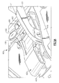
- FIG 2 illustrates a single external flap 24, multiples of which can be used to create the arrangement described above, and illustrated in Figure 1 .
- the external flap 24 has a flap surface 110 which is supported by two external flap support ribs 120.
- Each of the external flap support ribs 120 connects to a support arm 122.
- the support arms 122 each have a retaining member 154 for connecting the support ann 122 to a slider track 420 (illustrated in Figures 5A , 5B and 6 ).
- the illustrated flap support ribs 120 also include a hollow opening 136 which extends through the flap support ribs 120.
- the structure of the retaining member 154 is located on the end of each support arm 122, which is shown in greater detail, with an assembled view ( Figure 3A ) and an exploded view ( Figure 3B ).
- the retaining member 154 includes a retainer piece slot 222, multiple fastener holes 224, and a cavity 226. Received within the cavity 226 is a rotational bearing 228 portion of a slider block 230.
- the rotational bearing 228 portion of the slider block 230 includes a circumferential channel 232 ( Figure 3B ). While the opening 222 is referred to as a retainer piece slot 222, it could alternately be any shape designed to accommodate a retainer piece 240.
- a retainer piece: 240 is received in the retainer piece slot 222 and has a slot 242 corresponding to the cavity 226 and through holes 244 corresponding to each of the fastener holes 224.
- the rotational bearing 228 of the slider block 230 is received in the cavity 226.
- the slot 242 in the retaining piece 240 fits into the circumferential channel 232 of the rotational bearing 228, thereby holding the slider block 230 in place axially while allowing for rotation of the rotational bearing 228.
- Received within each of the fastener holes 224 of the retaining member 154 and the through holes 244 of the retaining piece 240 is a fastener 234 (such as a rivet or a bolt), which holds the retaining piece 240 in place.
- Each of the illustrated fastener holes 224 is a counter-sunk hole. By counter-sinking the fastener holes 224, the head end and tail end of the fasteners 234 are flush with the outside and inside surfaces of the retaining member 154 thereby preventing any interference issues once the external flap 24 is installed. While an arrangement using releasable mechanical fasteners to hold the retainer piece 240 in place is described above, alternative configurations, such as permanent or adhesive fasteners, could be utilized in place of the described configuration.
- FIG. 4 A cutout side view of the retaining member 154 is illustrated in Figure 4 .
- the retaining piece 240 is located in the retainer piece slot 222 of the retaining member 154 and fits into the circumferential channel 232 of the rotational bearing 228.
- the ends of the fasteners 234 and the rotational bearing 228 arc flush with an outside surface 260 of the retaining member 154, thereby allowing the support arm 122 and the retaining member 154 to slide in a slider track 420 (illustrated in Figures 5A and 5B ) without causing interference or clearance issues between the slider track 420, a track frame 410, and the outside surface 260 of the retaining member 154.
- Figures 5A and 5B illustrates a convection assembly for connecting the external flap arms 122 to the gas turbine engine 10 nozzle (illustrated in Figure 1 ).
- Figures 5A and 5B illustrate the retaining mechanism in a partially closed ( Figure 5A ) and an open ( Figure 5B ) position. While in the retracted position, the nozzle opening 22 (illustrated in Figure 1 ) is larger, thereby reducing the pressure of the exhaust gas and degreasing thrust. The converse is true when the external flap 24 is extended.
- the connection assembly has a track frame 410, a slider track 420, and a locking assembly 430,
- the slider track 420 and the track frame are located on the downstream end of the cowling, thereby connecting the external flap 24 to the cowling.
- the retaining member 154 is connected to the slider track 420 via a slider portion 238 (illustrated in Figures 3A , 3B, and 4 ) of the slider block 230, which extends into the slider track 420, and is capable of sliding along the slider track 420.
- the slider block 230 slides along the slider track 420, and thereby adjusts the positioning of the external flap 24 and the size of the opening 22.
- the position of the external flap 24 may be adjusted by adjusting the positions of the convergent and divergent flaps 32 (illustrated in Figure 1 ), which drag the external flaps 24 along with them as they are adjusted. Alternately, any other movement creating device may be utilized to adjust the external flap 24 positions.
- FIG 5C illustrates an exploded view of the retaining mechanism 400 assembly of Figures 5A and 5B .
- the slider track 420 has an opening 422 at one end which is blocked by a sliding locking mechanism 430.
- the opening 422 allows the external flap 24 to be attached to the turbine engine 10 via the retaining mechanism 154.
- the sliding locking mechanism 430 prevents the slider portion 238 of the slider block 230 from slipping out of the slider track 420 when the external flap 24 is installed and is in a fully extended position.
- the locking mechanism 430 is held in place via a bolt 432 connecting the locking mechanism 430 to the slider track 420.
- any other removable fastener could be used in place of the bolt 432 to achieve the same affect.
- the external flap 24 can be removed from the turbine engine 10 by removing the bolt 432 and sliding the locking mechanism 430 out of a locked position, thereby unblocking the opening 422 in the slider track 420. Once the locking mechanism 430 has been moved, the slider portion 238 of the slider block 230 can be removed from the slide track 420, separating the external flap 24 from the gas turbine engine 10. This configuration allows for easy replacement of damaged or worn external flaps 24. When the external flap 24 has been replaced with a new or repaired external flap 24, the locking mechanism 430 is again bolted to the slider track 420 and the new external flap 24 is locked in.
- FIG 6 illustrates an expanded view of the assembly of Figures 5A-5C .
- the external flap 24 has two support arms 122, each of which is connected to a slider track 420.
- Each support arm 122 has a retaining member 154 with a slider block portion 230 extending inwardly toward the opposite retaining member 154.
- the slider tracks 420 could be arranged such that the slider blocks 230 extend away from each other, or in any other suitable configuration.
- Each of the slider track assemblies is arranged in a configuration similar to the configuration illustrated in Figures 5A-5C .
Landscapes
- Engineering & Computer Science (AREA)
- Chemical & Material Sciences (AREA)
- Combustion & Propulsion (AREA)
- Mechanical Engineering (AREA)
- General Engineering & Computer Science (AREA)
- Turbine Rotor Nozzle Sealing (AREA)
- Control Of Turbines (AREA)
- Supercharger (AREA)
Abstract
Description
- The present disclosure is related to gas turbine engines, and particularly to external flaps for a gas turbine engine nozzle.
- Gas turbine engine nozzles include external flap assemblies which are opened or closed in order to vary the area of the nozzle opening. When the flaps are closed, the nozzle area is restricted, resulting in a smaller opening and greater thrust. When the flaps are opened, the nozzle is less restricted resulting in larger opening and less thrust, Multiple flaps are arranged in a circumferential manner around the nozzle opening, thereby allowing for a greater control over the size of the nozzle opening and the amount of thrust generated.
- Opening and closing mechanisms are relatively heavy, and can raise design concerns required to avoid interference with other aircraft components. Additionally, known mechanisms for connecting the external flaps to the gas turbine engine body cause disconnecting the external flap from the turbine engine to be difficult. This can result in more expensive repairs and longer repair times, should an external flap need to be replaced.
- Disclosed is an external flap connection assembly for a turbine engine nozzle which has a slider track and an external flap. The external flap has an external flap arm with a retaining member including a protruding slider block. The slider block is received in the slider track.
- Also disclosed is a retaining mechanism for connecting an external flap to an engine nozzle. The external flap has a support arm with a retaining member. The retaining member has a retainer slot and a cavity. A retainer piece is received in the retainer slot. A slider block has a first end received in the cavity, and is held in place by the retainer piece.
- Also disclosed is an external flap for a turbine engine nozzle. The external flap has at least one support arm with a retaining mechanism for connecting the external flap to a turbine engine body. The retaining mechanism has a retainer slot and a cavity. A slider block is received in the cavity and a retainer piece is received in the retainer slot, thereby holding the slider block in place.
- These and other features of the present invention can be best understood from the following specification and drawings, the following of which is a brief description.
-
-
Figure 1 illustrates a schematic diagram of a gas turbine engine. -
Figure 2 illustrates an external flap for a gas turbine engine nozzle. -
Figure 3A illustrates an isometric view of a retaining mechanism for connecting an external flap to a gas turbine engine nozzle. -
Figure 3B illustrates an exploded view of the retaining mechanism ofFigure 3A . -
Figure 4 illustrates a cut out side view of the retaining mechanism ofFigure 3A . -
Figure 5A illustrates a retaining mechanism connected to a slider track on a gas turbine engine nozzle in a partially extended position. -
Figure 5B illustrates the retaining mechanism ofFigure 5 with the external flap in a fully retracted position. -
Figure 5C illustrates an exploded view of the assembly ofFigure 5 . -
Figure 6 illustrates an external flap connected to a gas turbine engine via a pair effacing retaining mechanisms. -
Figure 1 illustrates a schematic diagram of agas turbine engine 10. Thegas turbine engine 10 includes anozzle 20 which expels air driven by afan 19, thereby producing thrust. Thenozzle 20 defines anopening 22 around a core housing 11. Thenozzle 20 is defined by a set ofexternal flaps 24, which are arranged circumferentially around the opening 22. Theexternal flaps 24 are shown schematically inFigure 1 , and can be opened or closed depending on the desired volume of the gas passing through thenozzle 20 and thereby controlling the direction of the thrust of theturbine engine 10. Theexternal flaps 24 arc connected to theopening 22 via a retaining mechanism (illustrated inFigures 2, 3A ,3B, and 4 ). Theexternal flaps 24 are further supported by adivergent flap 32 which is mechanically supported by amode strut 34 and ahinge structure 36, which allows theexternal flap 24 to move along with thedivergent flap 32. Thehinge structure 36 can also contain an actuator for controlling the movement of thedivergent flap 32. -
Figure 2 illustrates a singleexternal flap 24, multiples of which can be used to create the arrangement described above, and illustrated inFigure 1 . Theexternal flap 24 has aflap surface 110 which is supported by two externalflap support ribs 120. Each of the externalflap support ribs 120 connects to asupport arm 122. Thesupport arms 122 each have aretaining member 154 for connecting thesupport ann 122 to a slider track 420 (illustrated inFigures 5A ,5B and6 ). The illustratedflap support ribs 120 also include ahollow opening 136 which extends through theflap support ribs 120. - The structure of the retaining
member 154 is located on the end of eachsupport arm 122, which is shown in greater detail, with an assembled view (Figure 3A ) and an exploded view (Figure 3B ). Theretaining member 154 includes aretainer piece slot 222,multiple fastener holes 224, and acavity 226. Received within thecavity 226 is a rotational bearing 228 portion of aslider block 230. The rotational bearing 228 portion of theslider block 230 includes a circumferential channel 232 (Figure 3B ). While the opening 222 is referred to as aretainer piece slot 222, it could alternately be any shape designed to accommodate aretainer piece 240. - A retainer piece: 240 is received in the
retainer piece slot 222 and has aslot 242 corresponding to thecavity 226 and throughholes 244 corresponding to each of thefastener holes 224. The rotational bearing 228 of theslider block 230 is received in thecavity 226. Theslot 242 in theretaining piece 240 fits into thecircumferential channel 232 of therotational bearing 228, thereby holding theslider block 230 in place axially while allowing for rotation of therotational bearing 228. Received within each of thefastener holes 224 of theretaining member 154 and the throughholes 244 of theretaining piece 240 is a fastener 234 (such as a rivet or a bolt), which holds theretaining piece 240 in place. Each of the illustratedfastener holes 224 is a counter-sunk hole. By counter-sinking thefastener holes 224, the head end and tail end of thefasteners 234 are flush with the outside and inside surfaces of the retainingmember 154 thereby preventing any interference issues once theexternal flap 24 is installed. While an arrangement using releasable mechanical fasteners to hold theretainer piece 240 in place is described above, alternative configurations, such as permanent or adhesive fasteners, could be utilized in place of the described configuration. - A cutout side view of the
retaining member 154 is illustrated inFigure 4 . As described above, theretaining piece 240 is located in theretainer piece slot 222 of theretaining member 154 and fits into thecircumferential channel 232 of the rotational bearing 228. The ends of thefasteners 234 and the rotational bearing 228 arc flush with anoutside surface 260 of theretaining member 154, thereby allowing thesupport arm 122 and theretaining member 154 to slide in a slider track 420 (illustrated inFigures 5A and5B ) without causing interference or clearance issues between theslider track 420, atrack frame 410, and theoutside surface 260 of theretaining member 154. -
Figures 5A and5B illustrates a convection assembly for connecting theexternal flap arms 122 to thegas turbine engine 10 nozzle (illustrated inFigure 1 ).Figures 5A and5B illustrate the retaining mechanism in a partially closed (Figure 5A ) and an open (Figure 5B ) position. While in the retracted position, the nozzle opening 22 (illustrated inFigure 1 ) is larger, thereby reducing the pressure of the exhaust gas and degreasing thrust. The converse is true when theexternal flap 24 is extended. - The connection assembly has a
track frame 410, aslider track 420, and a lockingassembly 430, Theslider track 420 and the track frame are located on the downstream end of the cowling, thereby connecting theexternal flap 24 to the cowling. The retainingmember 154 is connected to theslider track 420 via a slider portion 238 (illustrated inFigures 3A ,3B, and 4 ) of theslider block 230, which extends into theslider track 420, and is capable of sliding along theslider track 420. As can be seen inFigures 5A and5B , theslider block 230 slides along theslider track 420, and thereby adjusts the positioning of theexternal flap 24 and the size of theopening 22. the position of theexternal flap 24 may be adjusted by adjusting the positions of the convergent and divergent flaps 32 (illustrated inFigure 1 ), which drag theexternal flaps 24 along with them as they are adjusted. Alternately, any other movement creating device may be utilized to adjust theexternal flap 24 positions. -
Figure 5C illustrates an exploded view of theretaining mechanism 400 assembly ofFigures 5A and5B . Theslider track 420 has anopening 422 at one end which is blocked by a slidinglocking mechanism 430. Theopening 422 allows theexternal flap 24 to be attached to theturbine engine 10 via theretaining mechanism 154. The slidinglocking mechanism 430 prevents theslider portion 238 of the slider block 230 from slipping out of theslider track 420 when theexternal flap 24 is installed and is in a fully extended position. Thelocking mechanism 430 is held in place via abolt 432 connecting thelocking mechanism 430 to theslider track 420. Alternatively, any other removable fastener could be used in place of thebolt 432 to achieve the same affect. - The
external flap 24 can be removed from theturbine engine 10 by removing thebolt 432 and sliding thelocking mechanism 430 out of a locked position, thereby unblocking theopening 422 in theslider track 420. Once thelocking mechanism 430 has been moved, theslider portion 238 of theslider block 230 can be removed from theslide track 420, separating theexternal flap 24 from thegas turbine engine 10. This configuration allows for easy replacement of damaged or wornexternal flaps 24. When theexternal flap 24 has been replaced with a new or repairedexternal flap 24, thelocking mechanism 430 is again bolted to theslider track 420 and the newexternal flap 24 is locked in. -
Figure 6 illustrates an expanded view of the assembly ofFigures 5A-5C . Theexternal flap 24 has twosupport arms 122, each of which is connected to aslider track 420. Eachsupport arm 122 has a retainingmember 154 with aslider block portion 230 extending inwardly toward the opposite retainingmember 154. Alternately, the slider tracks 420 could be arranged such that the slider blocks 230 extend away from each other, or in any other suitable configuration. Each of the slider track assemblies is arranged in a configuration similar to the configuration illustrated inFigures 5A-5C . - While the retaining mechanism and slider track assembly is described with regards to a variable nozzle system, it is understood that the system could be utilized in a thrust vectoring system with minimal modifications.
- Although an embodiment of this invention has been disclosed, a worker of ordinary skill in this art would recognize that certain modifications would come within the scope of this invention. For that reason, the following claims should be studied to determine the true scope and content of this invention.
Claims (15)
- An external flap connection assembly for a turbine engine nozzle (20) comprising;
a slider track (420); and
an external flap (24) having a retaining member (154) including a protruding slider block (230), wherein said slider block (230) is received in said slider track (420). - The external flap connection assembly of claim 1, wherein said slider track (420) comprises an open first end (422) such that said slider block (230) may be removed from said slider track (420).
- The external flap connection assembly of claim 2, wherein said open end (422) is blocked by a sliding locking assembly (430), said sliding locking assembly comprising a barrier portion and a fastener portion locking said barrier portion to said slider track (420).
- The external flap connection assembly of any preceding claim, wherein said retaining member (154) comprises a retainer slot (222), a cavity (226), and a plurality of retaining member fastener holes (224), wherein the slider block (230) is received in said cavity (226) and wherein a retainer piece (240), having a plurality of retainer piece fastener holes (244), is received in said retainer slot (222), and a plurality of fasteners (234) are received in said fastener holes (224,244).
- The external flap connection assembly of claim 4, wherein said slider block (230) comprises a rotational bearing (228) having a radial channel (232) and a slider portion (238) protruding axially away from said rotational bearing (228) and toward said slider track (420).
- The external flap connection assembly of claim 5, wherein said retainer piece (240) is at least partially received in said radial channel (232), thereby holding said slider block (230) in place.
- A retaining mechanism for connecting an external flap (24) to an engine nozzle (20) comprising:a support arm (122) having a retaining member (154), said retaining member (154) comprising a retainer slot (222) and a cavity (226);a retainer piece (240) received in said retainer slot (222); anda slider block (230) having a first end received in said cavity (226), and held therein by said retainer piece (240).
- The retaining mechanism of claim 7, wherein said retainer piece (240) comprises a slider block slot (242) corresponding to said cavity (226).
- The retaining mechanism of claim 7 or 8, wherein a first end of the slider block (230) comprises a rotational bearing (228), and a second end of the slider block (230) comprises a slider portion (238).
- The retaining mechanism of claim 9, wherein said rotational bearing (228) comprises a cylindrical portion and a circumferential retainer channel (232), wherein, optionally, said retainer piece (240) is partially received in said circumferential retainer channel (232) thereby holding said slider block (230) in place.
- The retaining mechanism of any of claims 7 to 10, further comprising a plurality of fasteners (234) protruding through said retaining member (154) and said retainer piece (240), thereby fixing said retainer piece (240) in said retainer cavity (226), each fastener (234) having a head surface flush with an inside surface of said retaining member (154).
- An external flap (24) for a turbine engine nozzle comprising:at least one support arm (122) having a retaining mechanism for connecting said external flap (24) to a turbine engine body,said retaining mechanism having a retainer slot (222) and a cavity (216);a slider block (230) at least partially received in said cavity (216); anda retainer piece (240) received in said retainer slot for engaging and retaining said slider block (230).
- The external flap of claim 12, wherein said slider block comprises a cylindrical bearing component (228) and a slider component (238) extending axially from said cylindrical bearing component (228), said cylindrical bearing component (228) being received in said cavity (226), said cylindrical bearing component (228) optionally comprising a circumferential channel (232) receiving at least a portion of said retainer piece (240).
- The eternal flap of claim 12 or 13, wherein said retaining mechanism further comprises a plurality of first fastener holes (224), and said retainer piece (240) further comprises a plurality of second fastener holes (244) corresponding to said plurality of first fastener holes (224), and further optionally comprising a plurality of fasteners (234), configured such that each fastener (234) is received in one of said first plurality of fastener holes (224) and one of said second plurality of said fastener holes (224), each of said fasteners (234) optionally comprising a head surface which is flush with a retaining mechanism surface.
- The external flap of claim 12, 13 or 14, further comprising a first and a second support arm (122), each of said support arms (122) having a retaining mechanism for connecting said external flap (24) to a turbine engine body, said retaining mechanisms optionally with facing interior surfaces.
Applications Claiming Priority (1)
| Application Number | Priority Date | Filing Date | Title |
|---|---|---|---|
| US12/794,816 US8931281B2 (en) | 2010-06-07 | 2010-06-07 | External flap retaining mechanism |
Publications (3)
| Publication Number | Publication Date |
|---|---|
| EP2392814A2 true EP2392814A2 (en) | 2011-12-07 |
| EP2392814A3 EP2392814A3 (en) | 2015-02-18 |
| EP2392814B1 EP2392814B1 (en) | 2016-08-17 |
Family
ID=44118233
Family Applications (1)
| Application Number | Title | Priority Date | Filing Date |
|---|---|---|---|
| EP11168713.3A Active EP2392814B1 (en) | 2010-06-07 | 2011-06-03 | External flap retaining mechanism for an exhaust nozzle |
Country Status (2)
| Country | Link |
|---|---|
| US (1) | US8931281B2 (en) |
| EP (1) | EP2392814B1 (en) |
Families Citing this family (3)
| Publication number | Priority date | Publication date | Assignee | Title |
|---|---|---|---|---|
| US9121432B2 (en) | 2012-12-14 | 2015-09-01 | United Technologies Corporation | Nut plate fastener with elongated fastener aperture |
| US9551294B2 (en) | 2013-02-04 | 2017-01-24 | United Technologies Corporation | Sliding nozzle flap assembly |
| US9599132B2 (en) | 2015-03-09 | 2017-03-21 | Rohr, Inc. | Anti-rotation lug for mounting components together |
Family Cites Families (39)
| Publication number | Priority date | Publication date | Assignee | Title |
|---|---|---|---|---|
| US1328064A (en) * | 1920-01-13 | Fastening device | ||
| US2976676A (en) * | 1952-10-27 | 1961-03-28 | Solar Aircraft Co | Variable jet nozzle with coacting shroud |
| US2846844A (en) | 1956-01-24 | 1958-08-12 | Ryan Aeronautical Co | Variable area thrust deflectoraugmenter for jet engines |
| US3004385A (en) | 1958-06-25 | 1961-10-17 | Gen Motors Corp | Variable convergent-divergent jet nozzle |
| US3091080A (en) | 1958-10-27 | 1963-05-28 | United Aircraft Corp | Control system for afterburning gas turbine engine |
| US3044258A (en) * | 1958-11-25 | 1962-07-17 | Gen Electric | Adjustable converging-diverging nozzle |
| US3592389A (en) | 1969-11-24 | 1971-07-13 | Gen Motors Corp | Flap linkage |
| US3794244A (en) | 1971-12-20 | 1974-02-26 | United Aircraft Corp | Seal centering and retention means |
| US3792815A (en) | 1972-11-24 | 1974-02-19 | United Aircraft Corp | Balanced flap converging/diverging nozzle |
| FR2277239A2 (en) | 1974-07-04 | 1976-01-30 | Snecma | EJECTION TUBE FLAP CONTROL DEVICE |
| US4181260A (en) | 1977-03-17 | 1980-01-01 | General Electric Company | Hydraulic actuation ring |
| US4176792A (en) | 1977-07-11 | 1979-12-04 | General Electric Company | Variable area exhaust nozzle |
| US4128208A (en) | 1977-07-11 | 1978-12-05 | General Electric Company | Exhaust nozzle flap seal arrangement |
| FR2437499A1 (en) | 1978-09-27 | 1980-04-25 | Snecma | IMPROVEMENT IN ADJUSTABLE NOZZLES FOR REACTION PROPELLERS |
| US4245787A (en) | 1978-12-01 | 1981-01-20 | General Electric Company | Variable area nozzle system |
| US4262868A (en) | 1979-05-29 | 1981-04-21 | The Boeing Company | Three-position variable camber flap |
| FR2470253A1 (en) | 1979-11-23 | 1981-05-29 | Snecma | ORIENTABLE TUYERE FOR REACTION PROPELLER |
| US4440346A (en) | 1981-12-28 | 1984-04-03 | United Technologies Corporation | Axially translatable variable area convergent/divergent nozzle |
| US4447009A (en) | 1981-12-28 | 1984-05-08 | United Technologies Corporation | Three-dimensional axially translatable convergent/divergent nozzle assembly |
| US4440347A (en) | 1981-12-28 | 1984-04-03 | United Technologies Corporation | Simplified means for balancing the loads on a variable area nozzle |
| US4456178A (en) | 1982-12-27 | 1984-06-26 | United Technologies Corporation | Exhaust nozzle assembly with dual unison ring structure |
| US4730952A (en) * | 1986-08-04 | 1988-03-15 | Wiley Edward R | Quick change mechanism for circular saw blades |
| US4767055A (en) | 1987-03-27 | 1988-08-30 | United Technologies Corporation | Method and linkage for positioning a convergent flap and coaxial arc valve |
| US4803756A (en) | 1988-02-17 | 1989-02-14 | United Technologies Corporation | Hinge pin retaining assembly having an integral slotted plate and hinge pin |
| US4884748A (en) | 1988-09-02 | 1989-12-05 | United Technologies Corporation | Fairing flap arrangement |
| US4994660A (en) | 1989-04-11 | 1991-02-19 | Hitachi, Ltd. | Axisymmetric vectoring exhaust nozzle |
| US5101533A (en) * | 1989-10-11 | 1992-04-07 | General Electric Company | Vibration damping hinge joints for variable area jet engine exhaust nozzles |
| US5048996A (en) * | 1990-07-02 | 1991-09-17 | Outboard Marine Corporation | Universal connector for retaining and linking members |
| US5031836A (en) * | 1990-07-10 | 1991-07-16 | United Technologies Corporation | Flexible fairing for airframe/nozzle interface |
| US5082182A (en) * | 1990-08-23 | 1992-01-21 | United Technologies Corporation | Thrust vectoring exhaust nozzle |
| US5261605A (en) | 1990-08-23 | 1993-11-16 | United Technologies Corporation | Axisymmetric nozzle with gimbled unison ring |
| US5437411A (en) | 1992-12-14 | 1995-08-01 | General Electric Company | Vectoring exhaust nozzle flap and seal positioning apparatus |
| US5666012A (en) | 1994-07-29 | 1997-09-09 | Innerspace Corporation | Rotating shaft seal |
| US6415560B1 (en) * | 2001-05-02 | 2002-07-09 | Cooper Technologies Company | Seismic bracing connector |
| WO2003013956A1 (en) | 2002-03-21 | 2003-02-20 | Nilesh Shriram Narvekar | Flap deployment mechanism with swing arms |
| US7153054B2 (en) * | 2004-05-20 | 2006-12-26 | United Technologies Corporation | Fastener assembly for attaching a non-metal component to a metal component |
| US7179011B1 (en) * | 2004-09-13 | 2007-02-20 | Murray Cohen | Integrated locking device |
| JP5264742B2 (en) | 2006-10-12 | 2013-08-14 | ユナイテッド テクノロジーズ コーポレイション | Variable area fan nozzle for a gas turbine engine fan nacelle with a sliding actuator |
| US7721549B2 (en) | 2007-02-08 | 2010-05-25 | United Technologies Corporation | Fan variable area nozzle for a gas turbine engine fan nacelle with cam drive ring actuation system |
-
2010
- 2010-06-07 US US12/794,816 patent/US8931281B2/en active Active
-
2011
- 2011-06-03 EP EP11168713.3A patent/EP2392814B1/en active Active
Non-Patent Citations (1)
| Title |
|---|
| None |
Also Published As
| Publication number | Publication date |
|---|---|
| EP2392814A3 (en) | 2015-02-18 |
| US8931281B2 (en) | 2015-01-13 |
| EP2392814B1 (en) | 2016-08-17 |
| US20110297758A1 (en) | 2011-12-08 |
Similar Documents
| Publication | Publication Date | Title |
|---|---|---|
| US11434850B2 (en) | Split sleeve hidden door thrust reverser | |
| EP2224100A2 (en) | Controlled fan stream flow bypass | |
| EP2837810B1 (en) | Thrust reverser unit | |
| US11149686B2 (en) | Thrust reverser assembly | |
| EP2466101A2 (en) | System and method for operating a thrust reverser for a turbofan propulsion system | |
| US20100150700A1 (en) | Bypass air scoop for gas turbine engine | |
| US20160273489A1 (en) | Fixed structure of a thrust reverser device | |
| US10047634B2 (en) | Actuator for aircraft turbine engine nacelle with notably one-piece annular rear part | |
| US20150291289A1 (en) | Asymmetric thrust reversers | |
| EP2392814A2 (en) | External flap retaining mechanism for an exhaust nozzle | |
| US10001080B2 (en) | Thrust reverse variable area fan nozzle | |
| US20090189013A1 (en) | Non-handed engine cowl doors for fuselage mounted turbine engines | |
| EP3591204B1 (en) | Thrust reverser with displaceable trailing edge body | |
| EP3323710B1 (en) | Self-locking alignment at a nacelle interface | |
| EP3323711B1 (en) | Lockable track system for a translating nacelle structure | |
| GB2488034A (en) | Reduced drag afterburner nozzle actuation system | |
| EP3798134B1 (en) | Linkage(s) between inner and outer cowl doors | |
| US10442543B2 (en) | Engine cowling of an aircraft gas turbine | |
| CN104854336A (en) | Synchronization system for a thrust reverser | |
| CN104271890A (en) | Thrust reverser with controlled-deployment blocking flap | |
| US12158122B2 (en) | Nacelle for an aircraft propulsion assembly comprising a flap for closing a recess for the passage of an actuator | |
| US20170183076A1 (en) | Door system for an exhaust gas duct of an auxiliary power unit of an aircraft | |
| US20160040626A1 (en) | Twin target thrust reverser module | |
| WO2021260285A1 (en) | Thrust reverser having three gates | |
| RU2367810C1 (en) | Aircraft jet engine outlet device |
Legal Events
| Date | Code | Title | Description |
|---|---|---|---|
| AK | Designated contracting states |
Kind code of ref document: A2 Designated state(s): AL AT BE BG CH CY CZ DE DK EE ES FI FR GB GR HR HU IE IS IT LI LT LU LV MC MK MT NL NO PL PT RO RS SE SI SK SM TR |
|
| AX | Request for extension of the european patent |
Extension state: BA ME |
|
| PUAI | Public reference made under article 153(3) epc to a published international application that has entered the european phase |
Free format text: ORIGINAL CODE: 0009012 |
|
| PUAL | Search report despatched |
Free format text: ORIGINAL CODE: 0009013 |
|
| AK | Designated contracting states |
Kind code of ref document: A3 Designated state(s): AL AT BE BG CH CY CZ DE DK EE ES FI FR GB GR HR HU IE IS IT LI LT LU LV MC MK MT NL NO PL PT RO RS SE SI SK SM TR |
|
| AX | Request for extension of the european patent |
Extension state: BA ME |
|
| RIC1 | Information provided on ipc code assigned before grant |
Ipc: F02K 1/12 20060101AFI20150115BHEP |
|
| 17P | Request for examination filed |
Effective date: 20150813 |
|
| RBV | Designated contracting states (corrected) |
Designated state(s): AL AT BE BG CH CY CZ DE DK EE ES FI FR GB GR HR HU IE IS IT LI LT LU LV MC MK MT NL NO PL PT RO RS SE SI SK SM TR |
|
| GRAP | Despatch of communication of intention to grant a patent |
Free format text: ORIGINAL CODE: EPIDOSNIGR1 |
|
| INTG | Intention to grant announced |
Effective date: 20160225 |
|
| GRAS | Grant fee paid |
Free format text: ORIGINAL CODE: EPIDOSNIGR3 |
|
| GRAA | (expected) grant |
Free format text: ORIGINAL CODE: 0009210 |
|
| AK | Designated contracting states |
Kind code of ref document: B1 Designated state(s): AL AT BE BG CH CY CZ DE DK EE ES FI FR GB GR HR HU IE IS IT LI LT LU LV MC MK MT NL NO PL PT RO RS SE SI SK SM TR |
|
| REG | Reference to a national code |
Ref country code: GB Ref legal event code: FG4D |
|
| REG | Reference to a national code |
Ref country code: CH Ref legal event code: EP |
|
| REG | Reference to a national code |
Ref country code: IE Ref legal event code: FG4D |
|
| REG | Reference to a national code |
Ref country code: AT Ref legal event code: REF Ref document number: 821352 Country of ref document: AT Kind code of ref document: T Effective date: 20160915 |
|
| REG | Reference to a national code |
Ref country code: DE Ref legal event code: R096 Ref document number: 602011029240 Country of ref document: DE |
|
| REG | Reference to a national code |
Ref country code: CH Ref legal event code: PCOW Free format text: NEW ADDRESS: 10 FARM SPRINGS RD., FARMINGTON, CT 06032 (US) |
|
| RAP2 | Party data changed (patent owner data changed or rights of a patent transferred) |
Owner name: UNITED TECHNOLOGIES CORPORATION |
|
| REG | Reference to a national code |
Ref country code: NL Ref legal event code: MP Effective date: 20160817 |
|
| REG | Reference to a national code |
Ref country code: LT Ref legal event code: MG4D |
|
| REG | Reference to a national code |
Ref country code: AT Ref legal event code: MK05 Ref document number: 821352 Country of ref document: AT Kind code of ref document: T Effective date: 20160817 |
|
| PG25 | Lapsed in a contracting state [announced via postgrant information from national office to epo] |
Ref country code: IT Free format text: LAPSE BECAUSE OF FAILURE TO SUBMIT A TRANSLATION OF THE DESCRIPTION OR TO PAY THE FEE WITHIN THE PRESCRIBED TIME-LIMIT Effective date: 20160817 Ref country code: NO Free format text: LAPSE BECAUSE OF FAILURE TO SUBMIT A TRANSLATION OF THE DESCRIPTION OR TO PAY THE FEE WITHIN THE PRESCRIBED TIME-LIMIT Effective date: 20161117 Ref country code: NL Free format text: LAPSE BECAUSE OF FAILURE TO SUBMIT A TRANSLATION OF THE DESCRIPTION OR TO PAY THE FEE WITHIN THE PRESCRIBED TIME-LIMIT Effective date: 20160817 Ref country code: FI Free format text: LAPSE BECAUSE OF FAILURE TO SUBMIT A TRANSLATION OF THE DESCRIPTION OR TO PAY THE FEE WITHIN THE PRESCRIBED TIME-LIMIT Effective date: 20160817 Ref country code: RS Free format text: LAPSE BECAUSE OF FAILURE TO SUBMIT A TRANSLATION OF THE DESCRIPTION OR TO PAY THE FEE WITHIN THE PRESCRIBED TIME-LIMIT Effective date: 20160817 Ref country code: HR Free format text: LAPSE BECAUSE OF FAILURE TO SUBMIT A TRANSLATION OF THE DESCRIPTION OR TO PAY THE FEE WITHIN THE PRESCRIBED TIME-LIMIT Effective date: 20160817 Ref country code: LT Free format text: LAPSE BECAUSE OF FAILURE TO SUBMIT A TRANSLATION OF THE DESCRIPTION OR TO PAY THE FEE WITHIN THE PRESCRIBED TIME-LIMIT Effective date: 20160817 |
|
| PG25 | Lapsed in a contracting state [announced via postgrant information from national office to epo] |
Ref country code: ES Free format text: LAPSE BECAUSE OF FAILURE TO SUBMIT A TRANSLATION OF THE DESCRIPTION OR TO PAY THE FEE WITHIN THE PRESCRIBED TIME-LIMIT Effective date: 20160817 Ref country code: GR Free format text: LAPSE BECAUSE OF FAILURE TO SUBMIT A TRANSLATION OF THE DESCRIPTION OR TO PAY THE FEE WITHIN THE PRESCRIBED TIME-LIMIT Effective date: 20161118 Ref country code: SE Free format text: LAPSE BECAUSE OF FAILURE TO SUBMIT A TRANSLATION OF THE DESCRIPTION OR TO PAY THE FEE WITHIN THE PRESCRIBED TIME-LIMIT Effective date: 20160817 Ref country code: LV Free format text: LAPSE BECAUSE OF FAILURE TO SUBMIT A TRANSLATION OF THE DESCRIPTION OR TO PAY THE FEE WITHIN THE PRESCRIBED TIME-LIMIT Effective date: 20160817 Ref country code: PT Free format text: LAPSE BECAUSE OF FAILURE TO SUBMIT A TRANSLATION OF THE DESCRIPTION OR TO PAY THE FEE WITHIN THE PRESCRIBED TIME-LIMIT Effective date: 20161219 Ref country code: AT Free format text: LAPSE BECAUSE OF FAILURE TO SUBMIT A TRANSLATION OF THE DESCRIPTION OR TO PAY THE FEE WITHIN THE PRESCRIBED TIME-LIMIT Effective date: 20160817 Ref country code: PL Free format text: LAPSE BECAUSE OF FAILURE TO SUBMIT A TRANSLATION OF THE DESCRIPTION OR TO PAY THE FEE WITHIN THE PRESCRIBED TIME-LIMIT Effective date: 20160817 |
|
| PG25 | Lapsed in a contracting state [announced via postgrant information from national office to epo] |
Ref country code: RO Free format text: LAPSE BECAUSE OF FAILURE TO SUBMIT A TRANSLATION OF THE DESCRIPTION OR TO PAY THE FEE WITHIN THE PRESCRIBED TIME-LIMIT Effective date: 20160817 Ref country code: EE Free format text: LAPSE BECAUSE OF FAILURE TO SUBMIT A TRANSLATION OF THE DESCRIPTION OR TO PAY THE FEE WITHIN THE PRESCRIBED TIME-LIMIT Effective date: 20160817 |
|
| REG | Reference to a national code |
Ref country code: DE Ref legal event code: R097 Ref document number: 602011029240 Country of ref document: DE |
|
| PG25 | Lapsed in a contracting state [announced via postgrant information from national office to epo] |
Ref country code: SM Free format text: LAPSE BECAUSE OF FAILURE TO SUBMIT A TRANSLATION OF THE DESCRIPTION OR TO PAY THE FEE WITHIN THE PRESCRIBED TIME-LIMIT Effective date: 20160817 Ref country code: DK Free format text: LAPSE BECAUSE OF FAILURE TO SUBMIT A TRANSLATION OF THE DESCRIPTION OR TO PAY THE FEE WITHIN THE PRESCRIBED TIME-LIMIT Effective date: 20160817 Ref country code: BE Free format text: LAPSE BECAUSE OF FAILURE TO SUBMIT A TRANSLATION OF THE DESCRIPTION OR TO PAY THE FEE WITHIN THE PRESCRIBED TIME-LIMIT Effective date: 20160817 Ref country code: CZ Free format text: LAPSE BECAUSE OF FAILURE TO SUBMIT A TRANSLATION OF THE DESCRIPTION OR TO PAY THE FEE WITHIN THE PRESCRIBED TIME-LIMIT Effective date: 20160817 Ref country code: SK Free format text: LAPSE BECAUSE OF FAILURE TO SUBMIT A TRANSLATION OF THE DESCRIPTION OR TO PAY THE FEE WITHIN THE PRESCRIBED TIME-LIMIT Effective date: 20160817 Ref country code: BG Free format text: LAPSE BECAUSE OF FAILURE TO SUBMIT A TRANSLATION OF THE DESCRIPTION OR TO PAY THE FEE WITHIN THE PRESCRIBED TIME-LIMIT Effective date: 20161117 |
|
| PLBE | No opposition filed within time limit |
Free format text: ORIGINAL CODE: 0009261 |
|
| STAA | Information on the status of an ep patent application or granted ep patent |
Free format text: STATUS: NO OPPOSITION FILED WITHIN TIME LIMIT |
|
| REG | Reference to a national code |
Ref country code: DE Ref legal event code: R082 Ref document number: 602011029240 Country of ref document: DE Representative=s name: SCHMITT-NILSON SCHRAUD WAIBEL WOHLFROM PATENTA, DE |
|
| 26N | No opposition filed |
Effective date: 20170518 |
|
| PG25 | Lapsed in a contracting state [announced via postgrant information from national office to epo] |
Ref country code: SI Free format text: LAPSE BECAUSE OF FAILURE TO SUBMIT A TRANSLATION OF THE DESCRIPTION OR TO PAY THE FEE WITHIN THE PRESCRIBED TIME-LIMIT Effective date: 20160817 |
|
| PG25 | Lapsed in a contracting state [announced via postgrant information from national office to epo] |
Ref country code: MC Free format text: LAPSE BECAUSE OF FAILURE TO SUBMIT A TRANSLATION OF THE DESCRIPTION OR TO PAY THE FEE WITHIN THE PRESCRIBED TIME-LIMIT Effective date: 20160817 |
|
| REG | Reference to a national code |
Ref country code: CH Ref legal event code: PL |
|
| REG | Reference to a national code |
Ref country code: IE Ref legal event code: MM4A |
|
| REG | Reference to a national code |
Ref country code: FR Ref legal event code: ST Effective date: 20180228 |
|
| PG25 | Lapsed in a contracting state [announced via postgrant information from national office to epo] |
Ref country code: IE Free format text: LAPSE BECAUSE OF NON-PAYMENT OF DUE FEES Effective date: 20170603 Ref country code: LU Free format text: LAPSE BECAUSE OF NON-PAYMENT OF DUE FEES Effective date: 20170603 Ref country code: CH Free format text: LAPSE BECAUSE OF NON-PAYMENT OF DUE FEES Effective date: 20170630 Ref country code: LI Free format text: LAPSE BECAUSE OF NON-PAYMENT OF DUE FEES Effective date: 20170630 |
|
| PG25 | Lapsed in a contracting state [announced via postgrant information from national office to epo] |
Ref country code: FR Free format text: LAPSE BECAUSE OF NON-PAYMENT OF DUE FEES Effective date: 20170630 |
|
| PG25 | Lapsed in a contracting state [announced via postgrant information from national office to epo] |
Ref country code: MT Free format text: LAPSE BECAUSE OF NON-PAYMENT OF DUE FEES Effective date: 20170603 |
|
| PG25 | Lapsed in a contracting state [announced via postgrant information from national office to epo] |
Ref country code: AL Free format text: LAPSE BECAUSE OF FAILURE TO SUBMIT A TRANSLATION OF THE DESCRIPTION OR TO PAY THE FEE WITHIN THE PRESCRIBED TIME-LIMIT Effective date: 20160817 |
|
| PG25 | Lapsed in a contracting state [announced via postgrant information from national office to epo] |
Ref country code: HU Free format text: LAPSE BECAUSE OF FAILURE TO SUBMIT A TRANSLATION OF THE DESCRIPTION OR TO PAY THE FEE WITHIN THE PRESCRIBED TIME-LIMIT; INVALID AB INITIO Effective date: 20110603 |
|
| PG25 | Lapsed in a contracting state [announced via postgrant information from national office to epo] |
Ref country code: CY Free format text: LAPSE BECAUSE OF NON-PAYMENT OF DUE FEES Effective date: 20160817 |
|
| PG25 | Lapsed in a contracting state [announced via postgrant information from national office to epo] |
Ref country code: MK Free format text: LAPSE BECAUSE OF FAILURE TO SUBMIT A TRANSLATION OF THE DESCRIPTION OR TO PAY THE FEE WITHIN THE PRESCRIBED TIME-LIMIT Effective date: 20160817 |
|
| PG25 | Lapsed in a contracting state [announced via postgrant information from national office to epo] |
Ref country code: TR Free format text: LAPSE BECAUSE OF FAILURE TO SUBMIT A TRANSLATION OF THE DESCRIPTION OR TO PAY THE FEE WITHIN THE PRESCRIBED TIME-LIMIT Effective date: 20160817 |
|
| PG25 | Lapsed in a contracting state [announced via postgrant information from national office to epo] |
Ref country code: IS Free format text: LAPSE BECAUSE OF FAILURE TO SUBMIT A TRANSLATION OF THE DESCRIPTION OR TO PAY THE FEE WITHIN THE PRESCRIBED TIME-LIMIT Effective date: 20161217 |
|
| REG | Reference to a national code |
Ref country code: DE Ref legal event code: R081 Ref document number: 602011029240 Country of ref document: DE Owner name: RAYTHEON TECHNOLOGIES CORPORATION (N.D.GES.D.S, US Free format text: FORMER OWNER: UNITED TECHNOLOGIES CORPORATION, HARTFORD, CONN., US |
|
| P01 | Opt-out of the competence of the unified patent court (upc) registered |
Effective date: 20230519 |
|
| PGFP | Annual fee paid to national office [announced via postgrant information from national office to epo] |
Ref country code: GB Payment date: 20240521 Year of fee payment: 14 |
|
| PGFP | Annual fee paid to national office [announced via postgrant information from national office to epo] |
Ref country code: DE Payment date: 20240521 Year of fee payment: 14 |