EP2392796A1 - Device for the emission reduction of a turboshaft engine and corresponding method - Google Patents
Device for the emission reduction of a turboshaft engine and corresponding method Download PDFInfo
- Publication number
- EP2392796A1 EP2392796A1 EP10290303A EP10290303A EP2392796A1 EP 2392796 A1 EP2392796 A1 EP 2392796A1 EP 10290303 A EP10290303 A EP 10290303A EP 10290303 A EP10290303 A EP 10290303A EP 2392796 A1 EP2392796 A1 EP 2392796A1
- Authority
- EP
- European Patent Office
- Prior art keywords
- catalytic converter
- heat
- turboshaft engine
- heat exchanger
- catalyst
- Prior art date
- Legal status (The legal status is an assumption and is not a legal conclusion. Google has not performed a legal analysis and makes no representation as to the accuracy of the status listed.)
- Granted
Links
- 230000009467 reduction Effects 0.000 title claims abstract description 24
- 238000000034 method Methods 0.000 title claims description 15
- 239000007789 gas Substances 0.000 claims abstract description 102
- 230000003197 catalytic effect Effects 0.000 claims abstract description 87
- 239000003054 catalyst Substances 0.000 claims abstract description 80
- MWUXSHHQAYIFBG-UHFFFAOYSA-N nitrogen oxide Inorganic materials O=[N] MWUXSHHQAYIFBG-UHFFFAOYSA-N 0.000 claims abstract description 51
- 238000002485 combustion reaction Methods 0.000 claims abstract description 48
- 238000007254 oxidation reaction Methods 0.000 claims abstract description 20
- 230000003647 oxidation Effects 0.000 claims abstract description 19
- 238000012546 transfer Methods 0.000 claims abstract description 14
- 229910002091 carbon monoxide Inorganic materials 0.000 claims abstract description 11
- 229930195733 hydrocarbon Natural products 0.000 claims abstract description 11
- 150000002430 hydrocarbons Chemical class 0.000 claims abstract description 11
- UGFAIRIUMAVXCW-UHFFFAOYSA-N Carbon monoxide Chemical compound [O+]#[C-] UGFAIRIUMAVXCW-UHFFFAOYSA-N 0.000 claims abstract description 10
- 239000002245 particle Substances 0.000 claims description 26
- 239000003638 chemical reducing agent Substances 0.000 claims description 24
- 238000002347 injection Methods 0.000 claims description 23
- 239000007924 injection Substances 0.000 claims description 23
- 229910052751 metal Inorganic materials 0.000 claims description 19
- 239000002184 metal Substances 0.000 claims description 19
- BASFCYQUMIYNBI-UHFFFAOYSA-N platinum Chemical group [Pt] BASFCYQUMIYNBI-UHFFFAOYSA-N 0.000 claims description 15
- 239000010457 zeolite Substances 0.000 claims description 15
- PNEYBMLMFCGWSK-UHFFFAOYSA-N aluminium oxide Inorganic materials [O-2].[O-2].[O-2].[Al+3].[Al+3] PNEYBMLMFCGWSK-UHFFFAOYSA-N 0.000 claims description 10
- XEEYBQQBJWHFJM-UHFFFAOYSA-N Iron Chemical compound [Fe] XEEYBQQBJWHFJM-UHFFFAOYSA-N 0.000 claims description 9
- 229910021536 Zeolite Inorganic materials 0.000 claims description 8
- HNPSIPDUKPIQMN-UHFFFAOYSA-N dioxosilane;oxo(oxoalumanyloxy)alumane Chemical compound O=[Si]=O.O=[Al]O[Al]=O HNPSIPDUKPIQMN-UHFFFAOYSA-N 0.000 claims description 8
- 238000006477 desulfuration reaction Methods 0.000 claims description 7
- 230000023556 desulfurization Effects 0.000 claims description 7
- 229910052593 corundum Inorganic materials 0.000 claims description 6
- 229910001845 yogo sapphire Inorganic materials 0.000 claims description 6
- 229910052742 iron Inorganic materials 0.000 claims description 5
- 229910052720 vanadium Inorganic materials 0.000 claims description 4
- LEONUFNNVUYDNQ-UHFFFAOYSA-N vanadium atom Chemical compound [V] LEONUFNNVUYDNQ-UHFFFAOYSA-N 0.000 claims description 4
- VYZAMTAEIAYCRO-UHFFFAOYSA-N Chromium Chemical compound [Cr] VYZAMTAEIAYCRO-UHFFFAOYSA-N 0.000 claims description 3
- RYGMFSIKBFXOCR-UHFFFAOYSA-N Copper Chemical compound [Cu] RYGMFSIKBFXOCR-UHFFFAOYSA-N 0.000 claims description 3
- 229910052804 chromium Inorganic materials 0.000 claims description 3
- 239000011651 chromium Substances 0.000 claims description 3
- 229910052802 copper Inorganic materials 0.000 claims description 3
- 239000010949 copper Substances 0.000 claims description 3
- QJGQUHMNIGDVPM-UHFFFAOYSA-N nitrogen group Chemical group [N] QJGQUHMNIGDVPM-UHFFFAOYSA-N 0.000 claims description 3
- 229910052761 rare earth metal Inorganic materials 0.000 claims description 3
- 150000002910 rare earth metals Chemical class 0.000 claims description 3
- ZOKXTWBITQBERF-UHFFFAOYSA-N Molybdenum Chemical compound [Mo] ZOKXTWBITQBERF-UHFFFAOYSA-N 0.000 claims description 2
- RTAQQCXQSZGOHL-UHFFFAOYSA-N Titanium Chemical compound [Ti] RTAQQCXQSZGOHL-UHFFFAOYSA-N 0.000 claims description 2
- 238000001914 filtration Methods 0.000 claims description 2
- 229910052750 molybdenum Inorganic materials 0.000 claims description 2
- 239000011733 molybdenum Substances 0.000 claims description 2
- 230000001590 oxidative effect Effects 0.000 claims description 2
- 230000001172 regenerating effect Effects 0.000 claims description 2
- 229910052719 titanium Inorganic materials 0.000 claims description 2
- 239000010936 titanium Substances 0.000 claims description 2
- 238000006722 reduction reaction Methods 0.000 abstract description 21
- CURLTUGMZLYLDI-UHFFFAOYSA-N Carbon dioxide Chemical compound O=C=O CURLTUGMZLYLDI-UHFFFAOYSA-N 0.000 abstract description 15
- 229910002092 carbon dioxide Inorganic materials 0.000 abstract description 12
- 238000010531 catalytic reduction reaction Methods 0.000 abstract description 6
- 238000010438 heat treatment Methods 0.000 abstract description 5
- 239000001569 carbon dioxide Substances 0.000 abstract description 3
- 239000000446 fuel Substances 0.000 description 22
- NINIDFKCEFEMDL-UHFFFAOYSA-N Sulfur Chemical compound [S] NINIDFKCEFEMDL-UHFFFAOYSA-N 0.000 description 13
- 229910052717 sulfur Inorganic materials 0.000 description 13
- 239000011593 sulfur Substances 0.000 description 13
- 238000006243 chemical reaction Methods 0.000 description 11
- 238000001816 cooling Methods 0.000 description 11
- QGZKDVFQNNGYKY-UHFFFAOYSA-N Ammonia Chemical compound N QGZKDVFQNNGYKY-UHFFFAOYSA-N 0.000 description 9
- 239000007788 liquid Substances 0.000 description 8
- 239000000203 mixture Substances 0.000 description 8
- IJGRMHOSHXDMSA-UHFFFAOYSA-N Atomic nitrogen Chemical compound N#N IJGRMHOSHXDMSA-UHFFFAOYSA-N 0.000 description 7
- GNTDGMZSJNCJKK-UHFFFAOYSA-N divanadium pentaoxide Chemical compound O=[V](=O)O[V](=O)=O GNTDGMZSJNCJKK-UHFFFAOYSA-N 0.000 description 6
- 239000012530 fluid Substances 0.000 description 6
- 229910052697 platinum Inorganic materials 0.000 description 6
- QVGXLLKOCUKJST-UHFFFAOYSA-N atomic oxygen Chemical compound [O] QVGXLLKOCUKJST-UHFFFAOYSA-N 0.000 description 5
- 239000001301 oxygen Substances 0.000 description 5
- 229910052760 oxygen Inorganic materials 0.000 description 5
- 239000012071 phase Substances 0.000 description 5
- 238000012545 processing Methods 0.000 description 5
- 238000011144 upstream manufacturing Methods 0.000 description 5
- KDLHZDBZIXYQEI-UHFFFAOYSA-N Palladium Chemical compound [Pd] KDLHZDBZIXYQEI-UHFFFAOYSA-N 0.000 description 4
- GWEVSGVZZGPLCZ-UHFFFAOYSA-N Titan oxide Chemical compound O=[Ti]=O GWEVSGVZZGPLCZ-UHFFFAOYSA-N 0.000 description 4
- 229910021529 ammonia Inorganic materials 0.000 description 4
- 150000002739 metals Chemical class 0.000 description 4
- 239000013618 particulate matter Substances 0.000 description 4
- XLYOFNOQVPJJNP-UHFFFAOYSA-N water Substances O XLYOFNOQVPJJNP-UHFFFAOYSA-N 0.000 description 4
- 230000009849 deactivation Effects 0.000 description 3
- 238000002156 mixing Methods 0.000 description 3
- 229910052757 nitrogen Inorganic materials 0.000 description 3
- 239000000126 substance Substances 0.000 description 3
- XTQHKBHJIVJGKJ-UHFFFAOYSA-N sulfur monoxide Chemical class S=O XTQHKBHJIVJGKJ-UHFFFAOYSA-N 0.000 description 3
- CBENFWSGALASAD-UHFFFAOYSA-N Ozone Chemical compound [O-][O+]=O CBENFWSGALASAD-UHFFFAOYSA-N 0.000 description 2
- VYPSYNLAJGMNEJ-UHFFFAOYSA-N Silicium dioxide Chemical compound O=[Si]=O VYPSYNLAJGMNEJ-UHFFFAOYSA-N 0.000 description 2
- XSQUKJJJFZCRTK-UHFFFAOYSA-N Urea Chemical compound NC(N)=O XSQUKJJJFZCRTK-UHFFFAOYSA-N 0.000 description 2
- 239000003463 adsorbent Substances 0.000 description 2
- 239000007864 aqueous solution Substances 0.000 description 2
- 230000000903 blocking effect Effects 0.000 description 2
- 239000004202 carbamide Substances 0.000 description 2
- 239000000919 ceramic Substances 0.000 description 2
- 230000001276 controlling effect Effects 0.000 description 2
- 230000003247 decreasing effect Effects 0.000 description 2
- 238000010586 diagram Methods 0.000 description 2
- TXKMVPPZCYKFAC-UHFFFAOYSA-N disulfur monoxide Inorganic materials O=S=S TXKMVPPZCYKFAC-UHFFFAOYSA-N 0.000 description 2
- 230000000694 effects Effects 0.000 description 2
- 238000005516 engineering process Methods 0.000 description 2
- 239000000284 extract Substances 0.000 description 2
- 230000006872 improvement Effects 0.000 description 2
- 230000033001 locomotion Effects 0.000 description 2
- 238000012423 maintenance Methods 0.000 description 2
- 230000004048 modification Effects 0.000 description 2
- 238000012986 modification Methods 0.000 description 2
- 239000005022 packaging material Substances 0.000 description 2
- 229910052763 palladium Inorganic materials 0.000 description 2
- -1 platinum group metals Chemical class 0.000 description 2
- 231100000572 poisoning Toxicity 0.000 description 2
- 230000000607 poisoning effect Effects 0.000 description 2
- 239000011148 porous material Substances 0.000 description 2
- 239000002243 precursor Substances 0.000 description 2
- 238000000746 purification Methods 0.000 description 2
- 238000011084 recovery Methods 0.000 description 2
- 238000011069 regeneration method Methods 0.000 description 2
- 230000001105 regulatory effect Effects 0.000 description 2
- 239000010948 rhodium Substances 0.000 description 2
- 229910052703 rhodium Inorganic materials 0.000 description 2
- MHOVAHRLVXNVSD-UHFFFAOYSA-N rhodium atom Chemical compound [Rh] MHOVAHRLVXNVSD-UHFFFAOYSA-N 0.000 description 2
- 230000007704 transition Effects 0.000 description 2
- 230000004913 activation Effects 0.000 description 1
- 230000000274 adsorptive effect Effects 0.000 description 1
- 229910000323 aluminium silicate Inorganic materials 0.000 description 1
- XKMRRTOUMJRJIA-UHFFFAOYSA-N ammonia nh3 Chemical compound N.N XKMRRTOUMJRJIA-UHFFFAOYSA-N 0.000 description 1
- 230000008901 benefit Effects 0.000 description 1
- 230000033228 biological regulation Effects 0.000 description 1
- 230000005540 biological transmission Effects 0.000 description 1
- 229910001593 boehmite Inorganic materials 0.000 description 1
- 150000001768 cations Chemical class 0.000 description 1
- 230000008859 change Effects 0.000 description 1
- 239000000571 coke Substances 0.000 description 1
- 150000001875 compounds Chemical class 0.000 description 1
- 230000006835 compression Effects 0.000 description 1
- 238000007906 compression Methods 0.000 description 1
- 238000009833 condensation Methods 0.000 description 1
- 230000005494 condensation Effects 0.000 description 1
- 239000000470 constituent Substances 0.000 description 1
- 239000002826 coolant Substances 0.000 description 1
- 239000013078 crystal Substances 0.000 description 1
- 230000007123 defense Effects 0.000 description 1
- 230000001419 dependent effect Effects 0.000 description 1
- 238000001514 detection method Methods 0.000 description 1
- 230000007613 environmental effect Effects 0.000 description 1
- 239000000835 fiber Substances 0.000 description 1
- 125000000524 functional group Chemical group 0.000 description 1
- 239000007792 gaseous phase Substances 0.000 description 1
- 239000005431 greenhouse gas Substances 0.000 description 1
- FAHBNUUHRFUEAI-UHFFFAOYSA-M hydroxidooxidoaluminium Chemical compound O[Al]=O FAHBNUUHRFUEAI-UHFFFAOYSA-M 0.000 description 1
- 238000009434 installation Methods 0.000 description 1
- 239000007791 liquid phase Substances 0.000 description 1
- 238000004519 manufacturing process Methods 0.000 description 1
- 238000002844 melting Methods 0.000 description 1
- 230000008018 melting Effects 0.000 description 1
- 229910044991 metal oxide Inorganic materials 0.000 description 1
- 150000004706 metal oxides Chemical class 0.000 description 1
- JKQOBWVOAYFWKG-UHFFFAOYSA-N molybdenum trioxide Chemical compound O=[Mo](=O)=O JKQOBWVOAYFWKG-UHFFFAOYSA-N 0.000 description 1
- 238000012544 monitoring process Methods 0.000 description 1
- 229910000069 nitrogen hydride Inorganic materials 0.000 description 1
- 229910000510 noble metal Inorganic materials 0.000 description 1
- TWNQGVIAIRXVLR-UHFFFAOYSA-N oxo(oxoalumanyloxy)alumane Chemical compound O=[Al]O[Al]=O TWNQGVIAIRXVLR-UHFFFAOYSA-N 0.000 description 1
- 239000008188 pellet Substances 0.000 description 1
- 239000010970 precious metal Substances 0.000 description 1
- 230000008569 process Effects 0.000 description 1
- 230000001737 promoting effect Effects 0.000 description 1
- 230000005855 radiation Effects 0.000 description 1
- 230000036632 reaction speed Effects 0.000 description 1
- 230000008929 regeneration Effects 0.000 description 1
- 229910052594 sapphire Inorganic materials 0.000 description 1
- 239000000377 silicon dioxide Substances 0.000 description 1
- 239000008275 solid aerosol Substances 0.000 description 1
- 239000007790 solid phase Substances 0.000 description 1
- 239000004071 soot Substances 0.000 description 1
- 238000001179 sorption measurement Methods 0.000 description 1
- 229910052815 sulfur oxide Inorganic materials 0.000 description 1
- 150000003467 sulfuric acid derivatives Chemical class 0.000 description 1
- 230000002195 synergetic effect Effects 0.000 description 1
- 239000004408 titanium dioxide Substances 0.000 description 1
- 229910052723 transition metal Inorganic materials 0.000 description 1
- 238000009834 vaporization Methods 0.000 description 1
- 230000008016 vaporization Effects 0.000 description 1
- 238000010792 warming Methods 0.000 description 1
- 229910003158 γ-Al2O3 Inorganic materials 0.000 description 1
Images
Classifications
-
- F—MECHANICAL ENGINEERING; LIGHTING; HEATING; WEAPONS; BLASTING
- F02—COMBUSTION ENGINES; HOT-GAS OR COMBUSTION-PRODUCT ENGINE PLANTS
- F02C—GAS-TURBINE PLANTS; AIR INTAKES FOR JET-PROPULSION PLANTS; CONTROLLING FUEL SUPPLY IN AIR-BREATHING JET-PROPULSION PLANTS
- F02C7/00—Features, components parts, details or accessories, not provided for in, or of interest apart form groups F02C1/00 - F02C6/00; Air intakes for jet-propulsion plants
- F02C7/08—Heating air supply before combustion, e.g. by exhaust gases
-
- B—PERFORMING OPERATIONS; TRANSPORTING
- B01—PHYSICAL OR CHEMICAL PROCESSES OR APPARATUS IN GENERAL
- B01D—SEPARATION
- B01D53/00—Separation of gases or vapours; Recovering vapours of volatile solvents from gases; Chemical or biological purification of waste gases, e.g. engine exhaust gases, smoke, fumes, flue gases, aerosols
- B01D53/34—Chemical or biological purification of waste gases
- B01D53/343—Heat recovery
-
- B—PERFORMING OPERATIONS; TRANSPORTING
- B01—PHYSICAL OR CHEMICAL PROCESSES OR APPARATUS IN GENERAL
- B01D—SEPARATION
- B01D53/00—Separation of gases or vapours; Recovering vapours of volatile solvents from gases; Chemical or biological purification of waste gases, e.g. engine exhaust gases, smoke, fumes, flue gases, aerosols
- B01D53/34—Chemical or biological purification of waste gases
- B01D53/92—Chemical or biological purification of waste gases of engine exhaust gases
- B01D53/94—Chemical or biological purification of waste gases of engine exhaust gases by catalytic processes
- B01D53/9459—Removing one or more of nitrogen oxides, carbon monoxide, or hydrocarbons by multiple successive catalytic functions; systems with more than one different function, e.g. zone coated catalysts
- B01D53/9477—Removing one or more of nitrogen oxides, carbon monoxide, or hydrocarbons by multiple successive catalytic functions; systems with more than one different function, e.g. zone coated catalysts with catalysts positioned on separate bricks, e.g. exhaust systems
-
- F—MECHANICAL ENGINEERING; LIGHTING; HEATING; WEAPONS; BLASTING
- F02—COMBUSTION ENGINES; HOT-GAS OR COMBUSTION-PRODUCT ENGINE PLANTS
- F02C—GAS-TURBINE PLANTS; AIR INTAKES FOR JET-PROPULSION PLANTS; CONTROLLING FUEL SUPPLY IN AIR-BREATHING JET-PROPULSION PLANTS
- F02C6/00—Plural gas-turbine plants; Combinations of gas-turbine plants with other apparatus; Adaptations of gas- turbine plants for special use
- F02C6/003—Gas-turbine plants with heaters between turbine stages
-
- F—MECHANICAL ENGINEERING; LIGHTING; HEATING; WEAPONS; BLASTING
- F23—COMBUSTION APPARATUS; COMBUSTION PROCESSES
- F23G—CREMATION FURNACES; CONSUMING WASTE PRODUCTS BY COMBUSTION
- F23G7/00—Incinerators or other apparatus for consuming industrial waste, e.g. chemicals
- F23G7/06—Incinerators or other apparatus for consuming industrial waste, e.g. chemicals of waste gases or noxious gases, e.g. exhaust gases
- F23G7/07—Incinerators or other apparatus for consuming industrial waste, e.g. chemicals of waste gases or noxious gases, e.g. exhaust gases in which combustion takes place in the presence of catalytic material
-
- F—MECHANICAL ENGINEERING; LIGHTING; HEATING; WEAPONS; BLASTING
- F23—COMBUSTION APPARATUS; COMBUSTION PROCESSES
- F23R—GENERATING COMBUSTION PRODUCTS OF HIGH PRESSURE OR HIGH VELOCITY, e.g. GAS-TURBINE COMBUSTION CHAMBERS
- F23R3/00—Continuous combustion chambers using liquid or gaseous fuel
- F23R3/40—Continuous combustion chambers using liquid or gaseous fuel characterised by the use of catalytic means
-
- B—PERFORMING OPERATIONS; TRANSPORTING
- B01—PHYSICAL OR CHEMICAL PROCESSES OR APPARATUS IN GENERAL
- B01D—SEPARATION
- B01D2251/00—Reactants
- B01D2251/20—Reductants
- B01D2251/206—Ammonium compounds
- B01D2251/2062—Ammonia
-
- B—PERFORMING OPERATIONS; TRANSPORTING
- B01—PHYSICAL OR CHEMICAL PROCESSES OR APPARATUS IN GENERAL
- B01D—SEPARATION
- B01D2251/00—Reactants
- B01D2251/20—Reductants
- B01D2251/206—Ammonium compounds
- B01D2251/2067—Urea
-
- B—PERFORMING OPERATIONS; TRANSPORTING
- B01—PHYSICAL OR CHEMICAL PROCESSES OR APPARATUS IN GENERAL
- B01D—SEPARATION
- B01D2255/00—Catalysts
- B01D2255/10—Noble metals or compounds thereof
- B01D2255/102—Platinum group metals
- B01D2255/1021—Platinum
-
- B—PERFORMING OPERATIONS; TRANSPORTING
- B01—PHYSICAL OR CHEMICAL PROCESSES OR APPARATUS IN GENERAL
- B01D—SEPARATION
- B01D2255/00—Catalysts
- B01D2255/10—Noble metals or compounds thereof
- B01D2255/102—Platinum group metals
- B01D2255/1025—Rhodium
-
- B—PERFORMING OPERATIONS; TRANSPORTING
- B01—PHYSICAL OR CHEMICAL PROCESSES OR APPARATUS IN GENERAL
- B01D—SEPARATION
- B01D2255/00—Catalysts
- B01D2255/20—Metals or compounds thereof
- B01D2255/206—Rare earth metals
- B01D2255/2065—Cerium
-
- B—PERFORMING OPERATIONS; TRANSPORTING
- B01—PHYSICAL OR CHEMICAL PROCESSES OR APPARATUS IN GENERAL
- B01D—SEPARATION
- B01D2255/00—Catalysts
- B01D2255/20—Metals or compounds thereof
- B01D2255/207—Transition metals
- B01D2255/20707—Titanium
-
- B—PERFORMING OPERATIONS; TRANSPORTING
- B01—PHYSICAL OR CHEMICAL PROCESSES OR APPARATUS IN GENERAL
- B01D—SEPARATION
- B01D2255/00—Catalysts
- B01D2255/20—Metals or compounds thereof
- B01D2255/207—Transition metals
- B01D2255/20723—Vanadium
-
- B—PERFORMING OPERATIONS; TRANSPORTING
- B01—PHYSICAL OR CHEMICAL PROCESSES OR APPARATUS IN GENERAL
- B01D—SEPARATION
- B01D2255/00—Catalysts
- B01D2255/20—Metals or compounds thereof
- B01D2255/207—Transition metals
- B01D2255/20738—Iron
-
- B—PERFORMING OPERATIONS; TRANSPORTING
- B01—PHYSICAL OR CHEMICAL PROCESSES OR APPARATUS IN GENERAL
- B01D—SEPARATION
- B01D2255/00—Catalysts
- B01D2255/20—Metals or compounds thereof
- B01D2255/207—Transition metals
- B01D2255/20761—Copper
-
- B—PERFORMING OPERATIONS; TRANSPORTING
- B01—PHYSICAL OR CHEMICAL PROCESSES OR APPARATUS IN GENERAL
- B01D—SEPARATION
- B01D2255/00—Catalysts
- B01D2255/20—Metals or compounds thereof
- B01D2255/207—Transition metals
- B01D2255/20769—Molybdenum
-
- B—PERFORMING OPERATIONS; TRANSPORTING
- B01—PHYSICAL OR CHEMICAL PROCESSES OR APPARATUS IN GENERAL
- B01D—SEPARATION
- B01D2255/00—Catalysts
- B01D2255/20—Metals or compounds thereof
- B01D2255/207—Transition metals
- B01D2255/20784—Chromium
-
- B—PERFORMING OPERATIONS; TRANSPORTING
- B01—PHYSICAL OR CHEMICAL PROCESSES OR APPARATUS IN GENERAL
- B01D—SEPARATION
- B01D2255/00—Catalysts
- B01D2255/50—Zeolites
-
- B—PERFORMING OPERATIONS; TRANSPORTING
- B01—PHYSICAL OR CHEMICAL PROCESSES OR APPARATUS IN GENERAL
- B01D—SEPARATION
- B01D2257/00—Components to be removed
- B01D2257/30—Sulfur compounds
- B01D2257/302—Sulfur oxides
-
- B—PERFORMING OPERATIONS; TRANSPORTING
- B01—PHYSICAL OR CHEMICAL PROCESSES OR APPARATUS IN GENERAL
- B01D—SEPARATION
- B01D2257/00—Components to be removed
- B01D2257/40—Nitrogen compounds
- B01D2257/404—Nitrogen oxides other than dinitrogen oxide
-
- B—PERFORMING OPERATIONS; TRANSPORTING
- B01—PHYSICAL OR CHEMICAL PROCESSES OR APPARATUS IN GENERAL
- B01D—SEPARATION
- B01D2257/00—Components to be removed
- B01D2257/50—Carbon oxides
- B01D2257/504—Carbon dioxide
-
- B—PERFORMING OPERATIONS; TRANSPORTING
- B01—PHYSICAL OR CHEMICAL PROCESSES OR APPARATUS IN GENERAL
- B01D—SEPARATION
- B01D2257/00—Components to be removed
- B01D2257/70—Organic compounds not provided for in groups B01D2257/00 - B01D2257/602
- B01D2257/702—Hydrocarbons
- B01D2257/7022—Aliphatic hydrocarbons
-
- B—PERFORMING OPERATIONS; TRANSPORTING
- B01—PHYSICAL OR CHEMICAL PROCESSES OR APPARATUS IN GENERAL
- B01D—SEPARATION
- B01D2259/00—Type of treatment
- B01D2259/45—Gas separation or purification devices adapted for specific applications
- B01D2259/4566—Gas separation or purification devices adapted for specific applications for use in transportation means
- B01D2259/4575—Gas separation or purification devices adapted for specific applications for use in transportation means in aeroplanes or space ships
-
- Y—GENERAL TAGGING OF NEW TECHNOLOGICAL DEVELOPMENTS; GENERAL TAGGING OF CROSS-SECTIONAL TECHNOLOGIES SPANNING OVER SEVERAL SECTIONS OF THE IPC; TECHNICAL SUBJECTS COVERED BY FORMER USPC CROSS-REFERENCE ART COLLECTIONS [XRACs] AND DIGESTS
- Y02—TECHNOLOGIES OR APPLICATIONS FOR MITIGATION OR ADAPTATION AGAINST CLIMATE CHANGE
- Y02E—REDUCTION OF GREENHOUSE GAS [GHG] EMISSIONS, RELATED TO ENERGY GENERATION, TRANSMISSION OR DISTRIBUTION
- Y02E20/00—Combustion technologies with mitigation potential
- Y02E20/14—Combined heat and power generation [CHP]
-
- Y—GENERAL TAGGING OF NEW TECHNOLOGICAL DEVELOPMENTS; GENERAL TAGGING OF CROSS-SECTIONAL TECHNOLOGIES SPANNING OVER SEVERAL SECTIONS OF THE IPC; TECHNICAL SUBJECTS COVERED BY FORMER USPC CROSS-REFERENCE ART COLLECTIONS [XRACs] AND DIGESTS
- Y02—TECHNOLOGIES OR APPLICATIONS FOR MITIGATION OR ADAPTATION AGAINST CLIMATE CHANGE
- Y02T—CLIMATE CHANGE MITIGATION TECHNOLOGIES RELATED TO TRANSPORTATION
- Y02T50/00—Aeronautics or air transport
- Y02T50/60—Efficient propulsion technologies, e.g. for aircraft
Definitions
- the invention relates to a device and method for an exhaust gas temperature and emission reduction for a lean bum turboshaft engine.
- the invention relates to gas turbine engines especially turboshaft engines which are widely used to power aircrafts as helicopters or wing aircrafts, wherein the wing aircraft size can range from small to medium civil aircraft up to large military transporters (like A 400 M).
- the energy produced in the turboshaft engine drives the power shaft.
- Energy is generated by burning a fuel-air mixture, which is characterized by a high excess of oxygen, high Lambda values (> 1) and a lean burner zone, thus providing a stream of hot expanding gas.
- the hot high-velocity gases are directed from the combustion chambers through turbine wheels which convert the axial movement of the gas to a rotary motion. This rotary power is used on the one hand to rotate the compressor and on the other hand to drive a powershaft, which drives a propeller or a rotor transmission.
- the emission reduction technologies can generally be assigned in two basic categories. On the one hand the implementation of primary measures serves to reduce combustion related emissions. On the other hand secondary measures for emission reduction are utilized after the combustion in order to reduce the emission concentrations of the exhaust gas.
- the combustion in turbo shaft engines is characterized by high excess of oxygen. These conditions are comparable to diesel engines. However, in turbo shaft engines, totally different exhaust gas temperatures and compositions are given. Therefore, the components which may be used for diesel engines may not be adapted without major changes to turbo shaft engines.
- turbo shaft engine comprising a heat energy converter and a catalytic converter according to the independent claims. Further embodiments are incorporated in the dependent claims.
- a turbo shaft engine comprises a combustion section producing emissions, a heat energy converter, a catalytic converter for reducing the emissions, wherein the catalytic converter is arranged downstream of the combustion section. Furthermore, the heat energy converter is arranged between the combustion section and the catalytic converter, wherein the heat energy converter is adapted to cool emission gases through heat transfer to an operative temperature range of the catalytic converter before feeding these gases to the catalytic converter.
- the heat energy converter is arranged between the combustion section and the catalytic converter. Adjusting the temperature range promotes the reduction of the emissions.
- the heat exchanger reduces the temperature of the exhaust gas to within the reaction range of the different exhaust species to be reduced.
- the temperature range suitable for a selective catalytic NO x reduction (SCR) in the presence of a catalyst lies between 250°C and 500 °C.
- the temperature range depends on the nature of the catalyst and accordingly to a potential introduction of reducing agent or other substance injected into the upstream flow of the catalyst.
- NO x nitrogen oxides
- HC hydrocarbons
- CO carbon monoxide
- CO 2 carbon dioxide
- PM particulate matter
- the heat energy converter of the turbo shaft engine is adapted to adjust the operative temperature range between 300 °C and 400 °C.
- the conversion conditions can be adjusted to a temperature range which is preferably about 300 °C to about 400 °C when the exhaust gas enters the at least one catalytic converter.
- a temperature of the gas at the exit of the combustion section exit covering the temperature range between 650 °C to 700 °C is decreased by about 300 °C to 400 °C.
- the infrared signature of e.g. a helicopter or a UAV-unmanned aircraft which is generated by the hot emitting exhaust gas by locally changing the infrared background level of the atmosphere, is significantly reduced and can prevent detection by infrared sensors of stationary or mobile monitoring platforms.
- the energetic converter of the turbo shaft engine further comprises a second heat exchanger arranged for heat transfer from the first heat exchanger into the compressed air section before entry into the combustion section in order to improve combustion efficiency.
- the heat extracted from the exhaust gas by the first heat exchanger is used to heat the compressed air.
- the warming of the air being combusted results in an improved combustion efficiency.
- the fuel injection can be lowered still maintaining the same engine efficiency. Therefore less fuel may be consumed and for example CO 2 emissions can be reduced.
- Using this thermal heat management the aircraft needs less fuel on board for covering the same distance thus saving weight and costs.
- At least one heat exchanger is selected from the group consisting of tubular heat exchangers, heat pipes and gas/gas heat exchangers.
- the tubular heat exchangers can be for example a shell and tube heat exchanger which consists of a series of tubes. These heat exchangers are typically used for high pressure applications and temperatures above 260 °C, because the shell and tube heat exchangers are robust due to their shape.
- Another type of heat exchanger is a heat pipe that can quickly transfer heat from one location to another.
- the air introduced into the exhaust section has to be cooler than the exhaust gas in order to remove heat.
- Air of the required temperature range is readily available from the atmosphere especially at high altitudes where the temperature is below 0° C and can be used for efficient cooling.
- This cooling air can especially be associated with the turbine section which is located in the exhaust section in order to cool turbine blades.
- gas/gas heat exchanger using cooling air can be combined with heat pipes or other types of heat exchangers.
- several sets of heat exchangers or heat pipes may be positioned circumferentially about the rotational axis of the gas turbine engine.
- intermediate fluids other than in a heat pipe may be used for transferring heat.
- a serial arrangement of the heat exchangers can be provided.
- a first heat exchanger cools down the exhaust gas entering the first catalyst using cooling air and before entering the second catalyst another heat exchanger uses the injection of a liquid reducing agent for further cooling down the gases leaving the first catalyst.
- a stepwise reduction of the temperature ranges corresponding to the different operations windows of the specific catalysts can be provided.
- the catalytic converter is selected from the group consisting of an oxidation catalyst, a catalytic particle filter, a selective catalyst for reduction of nitrogen oxides (SCR), a combination of SCR and oxidation catalyst, and an SCR catalyst with incorporated particle filter.
- the oxidation catalyst contains for example a honeycomb structure covered with a layer of a catalyst.
- This chemical layer contains catalytically active metal functional groups and comprises for example platinum group metals, other transition and noble metals and/or mixtures thereof.
- the additional metals are part of the uniform composition used to form the structural catalyst body.
- An oxidized catalytic removal of hydrocarbons as well as carbon monoxide can be done for example by Pt/Al 2 O 3 catalysts.
- Particle filters can also be used as catalytic converters such that a combination of a particle filter and catalytic converter as for example an oxidation catalyst is possible.
- the turboshaft engine further comprises a regenerative particulate filter and/or a device for desulfurization.
- a particle filter in order to separate solid aerosols as carbonaceous particles from the gas phase may be porous ceramics or flow through fibre filters and prevents that the downstream catalytic converter are deactivated or inhibited by the deposit of particles or coke on the catalyst surface. If the particle filter is arranged separately the particles as soot accumulated may be removed by regeneration. This is done for example by thermal engine management and increasing the exhaust temperature. If this regeneration method is used the first heat exchanger needs to be regulated to cool more effectively by increasing for example the injected amount of cooling air. Devices as a control unit, temperature sensors or mass flow controllers can be used for proper temperature regulation.
- a selective catalyst for desulfurization only needs to be installed upstream the catalysts if the total content of sulfur of the fuel is above a sulfur mixing ratio of 50 ppm. In the presence of sulfur the catalytic components can be poisoned and the active catalytic area can be reduced by blocking the active sites of the catalyst. If a desulfurization is necessary it can be done by a adsorbing structure which may contain metals such as Vanadium, Iron, Chromium, a platinum group metal, a rare earth metal or zeolites. The presence of excess oxygen enhances the sulfur adsorption because SO 2 is oxidized to the SO 3 , which is more easily adsorbed by the desulfurization device.
- the catalytic converter or desulfurization device comprises at least one metal or a metal layer by elements selected from the group Titanium, Vanadium, Molybdenum, Chromium, Iron, Copper; Cer and rare earth metals.
- These metals can be in form of oxides or sulfates.
- the oxidation catalyst comprises a platinum group metal on a monolith support for an oxidative catalytic removal of hydrocarbons and carbon monoxides.
- the precious metals used in oxidation catalyst applications are platinum, palladium and rhodium.
- palladium and platinum metals are catalysts with high activities for CO and HC oxidation reactions and they are less prone to poisoning the catalyst compared to metal oxide catalysts.
- HCs and CO which are precursors of ozone can be efficiently reduced.
- a reduction of CO contributes to maintain the background levels of this trace gas.
- the form of the catalytic converter can be monolithic such that a rapid and effective contacting with the exhaust gas flow is promoted with a pressure drop as low as possible in order to not influence the engine performance.
- the oxidation catalyst is a platinum Al 2 O 3 catalyst.
- Aluminum oxide Al 2 O 3 has many modifications from the porous ⁇ -Al 2 O 3 to non-porous ⁇ -Al 2 O 3 (> 1100°C), wherein the solid- solid phase transitions depend on the temperature.
- One important parameter for the efficiency of a catalyst is the active surface area. Therefore the modifications Al 2 O 3 (boehmite), with a surface area of 200-300 m 2 /g, which is stable at temperatures below 375° C, and the porous ⁇ -Al 2 O 3 are preferable.
- the particle filter and/or the selective catalyst for nitrogen oxides are zeolite based.
- Zeolite based means that the adsorbent-catalyst is mainly composed of zeolite which are crystalline aluminosilicates capable of adsorbing other compounds as well as a variety of different cations into their crystal lattice.
- the zeolites are capable of adsorbing molecules which have to be dealt with in the adsorptive purification of gases as for example oxides of nitrogen and lower hydrocarbons.
- the zeolite based adsorbent-catalyst can comprise a catalyst component supported thereon, said component being coated for example on a honeycomb structure.
- zeolites can be exploited in order to reduce particulate matter and/or nitrogen oxides in exhaust gas.
- a combination with a particle filter and a DENOx catalyst can be realized and the adsorbability of zeolite and the catalytic activity of the catalyst can act synergistically to provide an improved ability for purification of the exhaust gas.
- DENOx catalysts optimize a selective catalytic reduction (SCR) of nitrogen oxides.
- SCR selective catalytic reduction
- the selective catalytic NO x reduction SCR involves the reduction of NO x by ammonia NH 3 over the catalyst. These catalysts operate in a temperature range between about 300 and 400 °C. By using the first heat exchanger, these temperatures can easily be achieved.
- the zeolites are selected with a Si/Al ratio, which provide a heat resistance to said temperature window.
- the zeolite based catalyst comprises at least one metal or a metal layer by elements selected from the group copper, cer, iron and platinum.
- Zeolites which are doped with metal such as Cu, Ce, Fe, and Pt enhance the efficiency of the catalytic converter.
- a turbo shaft engine further comprises an injection device, wherein the injection device is adapted to inject at least one nitrogen containing reducing agent before the emission gases enter a selective catalytic converter (SCR).
- SCR selective catalytic converter
- the injection device can be a high velocity or high pressure nozzle in order to homogenously distribute the reducing agent over the whole cross section of the gas turbine cross section.
- the reducing agent can be introduced in the gaseous phase or in the liquid phase.
- the injection device can either be a grid or a metering lance in order to achieve the best distribution and mixing with the exhaust gas. This injection can also be used for further cooling of the exhaust gas. For example, water containing the reducing agent can be used to cool down the air temperature to the temperature window of the selective catalytic converter.
- an aircraft comprising a turbo shaft engine, further comprising a heat energy converter and a catalytic converter for reducing the emissions, wherein the heat energy converter is adapted to cool emission gases through heat transfer to an operative temperature range of the catalytic converter before feeding these gases to the catalytic converter.
- the infrared signature is reduced. Therefore the exhaust plume as well as heated tail pipe metals are less detectable by IR detectors.
- a narrow temperature range can be adjusted for a HC/SCR catalyst.
- the metal based catalysts do not lose their selectivity and efficiency due to too high temperature ranges.
- the selective catalytic reduction of nitrogen oxides SCR is an efficient way to remove NO x from a lean burning gas turbine engine as the turbo shaft engine.
- the engine efficiency can be improved by the option of exhaust gas energy recovery so that the overall CO 2 emissions can be reduced.
- the latter cannot be reduced by the usual exhaust gas processing systems arranged in the exhaust section.
- a method for exhaust gas processing for a turbo shaft engine comprising the following steps: reducing an exhaust gas temperature of a turbo shaft engine by a first heat exchanger to an operative temperature range of a downstream catalytic converter; injecting a reducing agent in the exhaust gas by an injection device before the emission gases enter a selective catalytic converter; reducing gas emission of the exhaust gas by at least one catalytic converter; and filtering particle matter by a particle filter.
- the exhaust emissions as particles and gases can be reduced to a higher degree as this will be possible by a combustion chamber improvement.
- the method further comprises: transferring the heat recovered by the first heat exchanger to a second heat exchanger into the compressed air section of the turbo shaft engine before entering the combustion section in order to improve combustion efficiency.
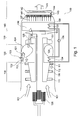
- Fig. 1 shows schematically a turbo shaft engine 100.
- the figure shows a cross-section through a casing 139 which is symmetrically and circumferentially disposed about an engine shaft 138 which extends out of the front.
- the shaft power produced by the free turbine 132 extracts the energy from the exhaust gas and transfers it via a gear box 128 to a receiving member such as a rotor of a helicopter (not shown).
- the turbo shaft comprises an intake area from where intake air 101 is delivered to the compressor section 110.
- This compressor may comprise several stages 111 in order to compress the air.
- the compressed air 112 enters in serial flow the combustion section 120.
- In this combustion section is a nozzle 122 and an ignition 123 located in order to inject fuel and burn the fuel/air-mixture 121 creating downstream a burning zone 124.
- the gases burned during the combustions are then discharged at great speed to the following turbine section 130.
- the high pressure turbine 131 extracts energy in order to drive the compressor.
- the low pressure of free turbine 132 is used to convert the energy into the output of shaft power.
- the air 125 is then delivered to the exhaust section 140.
- a heat exchanger 133 can be located in the volume 136, which is situated downstream the turbine 132. After passing the heat exchanger, the air 137 can enter a first catalytic converter 141 in order to reduce emissions.
- the heat exchanger 133 is arranged in order to decrease the temperature such that the first catalytic converter may efficiently catalyze the emissions.
- an injection device 144 is used in order to inject a reducing agent which is contained in a container 143.
- This reducing agent can either be gaseous or liquid. If using a liquid reducing agent, it can also be used for cooling down the air to the operative temperature of the downstream catalytic converter 142.
- This catalytic converter may for example be a nitrogen oxide SCR catalytic converter.
- the incoming air can be heated.
- the heat can be recovered from the first heat exchanger 133 to a second heat exchanger 134 which is located in the entrance of the combustion section.
- the heat exchanging system may comprise a medium in the inside of a tubular heating devices which is pumped by a pump 135 from the exhaust section in direction to the entrance of the combustion section 120.
- the heat exchangers may also be heat pipes.
- Heat pipes consist of three basic components: a container, a working fluid, and a capillary structure.
- the fluid possesses a high latent heat of vaporization in order to transfer large amount of heat with minimum fluid flow. Vapour can flow through the system and condenses back into a liquid at the cold interface releasing this latent heat.
- the liquid within the heat exchanger is vaporized by the hot exhaust air flowing across the heat exchangers in the volume 136 thus absorbing the heat. This cools the air such that the operative windows of the following catalysts are achieved.
- the vaporize fluid then can expand back the channels of the heat pipes toward the relatively cool region of the entrance of the combustion section, where the vapour again condenses. Such the differences in temperature between the volume 136 and the air 112 trigger a heat transfer cycle.
- the total volume 136 can be cooled down efficiently.
- the volume 136 can alternatively be cooled down by a housing, which contains a liquid cooling medium. The installation of such a housing is also possible around a catalytic converter.
- the first heat exchanger is necessary for the catalytic converters which are located downstream of this heat exchanger.
- the first heat exchanger can for example be a gas/gas heat exchanger by introducing air for example bypassed from the compressor in order to cool the air volume 136.
- Other possibilities to cool down the air are liquid/air heat exchangers, which is for example shown by the injection device 144 and the container 143, wherein the container 143 can contain an aqueous solution for example of urea with temperatures below the exhaust gas.
- an injection of this air through one or several nozzles will cool down the air efficiently in order to use the following SCR catalyst.
- the first catalytic converter 141 may be a oxidation catalyst layered with platinum or rhodium promoting for example the oxidation of CO to CO 2 : 2 CO + O 2 ⁇ 2 CO 2
- the second catalytic converter 142 may be a SCR selective catalytic reducer, wherein the catalysts may for example be a metal doped zeolites, titanium dioxide, vanadium pentoxide (V 2 O 5 ) or molybdenum oxide (MoO 3 ).
- the denitrification reaction comprises the reaction of nitrogen oxide species in the exhaust gas such as nitrogen oxides (NO or NO 2 ) With a reducing agent, such as ammonia or urea, the production of the stable diatomic nitrogen N 2 and water is promoted.
- a reducing agent such as ammonia or urea
- the zeolite-based catalyst have a poor hydrothermal stability. Therefore, it is important to operate the SCR process in the relatively small temperature window between 300 and 400 °C.
- the catalytic converters 141 and 142 can be used in any desired form such as particles, pellets, cylinders or monoliths. In case of particles or any other products stored in bulk a container has to be provided. For maintenance of the catalytic converters an access to these parts of changing or controlling can be provided.
- the two catalysts 141 and 142 are chosen such that the first catalyst can be operated at higher temperature than the second catalyst.
- the operating range for an oxidation catalyst of hydrocarbons and carbon monoxide is usually in a higher temperature range than the selective catalytic reduction, which is much narrower and also lower.
- undesirable exhaust constituents such as carbon monoxides, hydrocarbons and particle matter, which can be filtered by a combination of one of the catalysts and a particle filter, can be significantly reduced.
- it is necessary that the sulfur content of the fuel used is rather low and does not exceed 50 ppm (parts per million).
- Fig. 1 shows a turbo shaft engine with a power shaft extended out the front
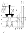
- Fig. 2 shows a turbo shaft engine with a power shaft extending out the back.
- the engine shown in Fig. 1 uses fuels which have sulfur contents below 50 ppm
- the engine shown in Fig. 2 uses fuel with a sulfur content above 50 ppm. Therefore there is a need to protect the sulfur sensitive catalytic converters arranged downstream in the exhaust flow.
- the function of the temperature is shown in the lower diagram e in relation to the location x along the rotational axis or power shaft of the engine.
- the temperature is shown in °C on the ordinate.
- the graph line 203 refers to the temperature without heat exchangers and the dash dotted line 204 shows temperature if using the two heat exchangers 201 and 202. This graph is only schematically and not to scale.
- the turbo shaft engine of Fig. 2 consists of the following sections, firstly the compressor section 201, the combustion section 220, the turbine section 230, and finally the exhaust section 240.
- the rotational power produced by the free turbine which his connected to the turbo shaft 231 can be delivered to drive an aircraft propeller, a helicopter rotor system, or any other rotor system not shown.
- a first catalyst 241 comprising for example a desulfurisation device and/or a catalytical particulate filter, and a second catalyst 242 for a selective catalytic reduction or also said SCR or DENO x step.
- These two catalytic converters form an exhaust treatment assembly 243 in order to reduce the emissions of the exhaust gas and emit it to the atmosphere.
- zeolites can operate in a temperature range of about 350 °C to about 600 °C. However, above 600 °C, a deactivation at these exposure temperatures can take place.
- a desulfurisation device 241 is arranged upstream the following catalytic converters.
- the sulfur oxide adsorbent 241 be placed on a support as ceramics or Silica and Alumina. This sulfur oxide adsorbent effectively protects and maintains the activity and life time of the downstream catalytic converter, which may be used to catalyse the conversion of NO x to inert products.
- a SCR catalysts also catalytic oxidation catalysts for CO and unburned HCs can be protected against sulfur deposits.
- a temperature sensor (not shown). If for example the pilot increases the flow of fuel injected into the combustion chamber, this would result in an increasing gas temperature in the high pressure turbine, therefore a control has to take place in order to increase the cooling, for example by gas/gas heat exchangers, which may work additionally to other heat exchangers as for example heat pipes.
- the cooling air can also be introduced in the turbine section in order to protect the turbines from temperatures which are higher than the melting point of the rotor blades.
- the temperature of the intake air has usually the temperature of the outer atmosphere which is shown in the range of 0 °C or 10 °C and may vary several tens of °C depending on the altitude.
- This graph is only schematically and not to scale, such that the shown temperature line may vary by about +/-10 °C in the direction of the axis of ordinate.
- the intake air temperature will increase in the compressor during the compression to around 250 or 260 °C. Without using a heat exchanger the temperature of graph 203 stays stable until the ignition and injection of the fuel (see second and third crosses at graph 203). At about the location of the flame beginning (see third cross on graph line 203) the temperature increases the temperature continuously until the end of the combustion section.
- the air When entering the turbine section, the air again cools down from around 900 °C to 700 °C (see graph line 203). In the exhaust section, the air usually stays at the level which was reached downstream the turbine section, which may be in the range of 750 to 600 °C. Flame temperatures usually depend on the fuel amount used and the air/fuel-mixture. By increasing the amount of oxygen i.e. very lean air/fuel-mixtures, the flame temperature can be lowered. Thus, if the air temperature measured by the temperature sensor is for example too high, it can also be controlled by adjusting the fuel injection rate.
- the dotted dashed line 204 shows the temperature function in dependence of the location in the turbo shaft engine using the heat exchangers 201 and 202.
- the heat exchanger 202 in the beginning of the combustion section before the flame is ignited, heats the air which is compressed to a higher temperature.
- the heating means or heat exchanger 202 is connected to the heating means or heat exchanger 201 in order to transfer the heat of the exhaust gas in the exhaust section 240 to the combustion section 220.
- the heat exchanger 202 is capable of increasing the temperature of the compressed air before it is ignited.
- heat exchangers are only sown schematically in Fig. 2 . They can also be gas/gas heat exchangers, wherein a current of hot gas, which is collected at the outlet of the turbine section, is reinjected into the combustion section. Depending on the amount of hot air injected, the air/fuel mixture will increase its temperature. This increase in temperature causes an increase in the power delivered by the turbine engine. In the case shown, the heat transfer achieves a temperature increase of 200 K. The temperature increase can also be adjusted to lower increases as from 50 K to 200 K. If the parts of the high pressure turbine are not cooled down by an additional heat exchanger, the parts have to be dimensioned as to withstand the increase in temperature, which may lie above 900 °C. Alternatively the fuel consumption and flame temperatures can be reduced as long as the same engine efficiency is achieved compared to the arrangement without heat exchangers. By this heat exchanger series the overall fuel consumption can be reduced, which lowers all gas emissions including CO 2 of the turbo shaft.
- turboshaft driven aircrafts with this kind of thermal management are not easily detectible by an infrared detector from the ground or other observation platform. Due to the use of a turbo shaft, a potential catalyst induced pressure drop can be tolerated and does usually not interfere with the engine operation. This is contrary to turbojet engines, which need the pressure in order to create the thrust and propulsion for the aircraft. However a blocking of the particle filter or catalytic converter has to be prevented by regular maintenance.
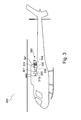
- Fig. 3 shows a helicopter 300 with a rotor 302 which is rotated by a turbo shaft engine via the gear box 303.
- the turbo shaft engine 301 comprises of a compressor, a combustion section 320, a turbine section 30 as well as an exhaust section 340.
- a heat exchanger is located in order to cool down the air to the operative temperatures of the first catalyst 341 and the second catalyst 342.
- the exhaust gas 350 is thereafter emitted to the atmosphere. If these helicopters are used for military, it is an advantage to cool down the exhaust temperature of the exhaust gas 350 such that the infrared signature is reduced. Detectors from the ground or from another aircraft or mobile platform cannot well differentiate these low infrared signatures in relation to the background signatures. Thus, the security of the military pilots can be increased.
- the exhaust gas processing catalysts assembly reduces emission such as hydrocarbons, carbon monoxide, and optionally particulate matter or nitrogen oxides.
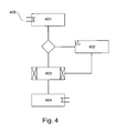
- Fig. 4 shows a flow chart of the steps of a method for exhaust gas processing as well as the option of exhaust gas energy recovery for improving engine efficiency.
- the method comprises the step 201, wherein an exhaust gas temperature of a turbo shaft engine is reduced by a first heat exchanger to an operative temperature range of a downstream catalytic converter.
- the reaction of the reduction of the nitrogen oxides with for example ammonia is effected between temperatures of 250 °C and 450 °C in the presence of a catalyst.
- the reaction temperature is higher than 450 °C, the reaction speed of oxidation of the NH 3 is faster, and rather the oxidation of the ammonia takes place preferentially than the reaction of reduction of the nitrogen oxides. Therefore, the efficiency of the catalytic converter is reduced.
- Temperatures lower than 250 °C rather speed down the reaction of reducing nitrogen oxides. Therefore, a mean temperature between 300 °C and 350 °C is preferred.
- a reducing agent can be injected in step 202.
- This reducing agent injection allows to selectively reducing for example nitrogen by the injection of a nitrogen containing substance into the emission gases.
- the first injection step can also be used to further reduce the temperature before the catalytic converter.
- Ammonia in gas phase reduces selectively nitrogen oxides (SCR) and is also suitable as a reducing agent for exhaust gas treatment in the presence of an excess of oxygen.
- the temperature windows may be adjusted if another catalyst or another reducing agent is used.
- a special injection device as well as the container which is adjusted to the outer casing has to be arranged. A good mixing of the exhaust gas and the reducing agent is necessary to have a contact with the reducing agent such that the reduction can efficiently take place.
- the first heat exchanger can be a liquid/air heat exchanger in order to reduce the gas temperature.
- Step 203 comprises the reduction of gas emission products of an exhaust gas by at least one catalytic converter.
- the gaseous emissions can be for example carbon monoxide, hydrocarbons or, after injection of a reducing agent, also a selective catalytic reduction as said above.
- a particulate filter can be combined with these catalysts. Because the concentrations of HCs, NO x ,CO and PM in the exhaust gas varies according to the type of engine, air/fuel ratio and phase of engine operation, controlling of the engine conditions as well as the converter conditions is necessary. This can be done by a central control unit in combination with suited sensors (temperature, pressure) regulating the heat exchangers in dependence from the engine conditions.
- Another optional step 204 is to transfer the heat recovered by the first heat exchanger to a second heat exchanger into the compressed air section of the turbo shaft engine before entry in the combustion section in order to improve combustion efficiency.
- fuel can be used and the overall emissions can be reduced, especially the CO 2 emissions.
Landscapes
- Engineering & Computer Science (AREA)
- Chemical & Material Sciences (AREA)
- Combustion & Propulsion (AREA)
- Environmental & Geological Engineering (AREA)
- Mechanical Engineering (AREA)
- General Engineering & Computer Science (AREA)
- Chemical Kinetics & Catalysis (AREA)
- Biomedical Technology (AREA)
- Analytical Chemistry (AREA)
- General Chemical & Material Sciences (AREA)
- Oil, Petroleum & Natural Gas (AREA)
- Health & Medical Sciences (AREA)
- Exhaust Gas After Treatment (AREA)
Abstract
Description
- The invention relates to a device and method for an exhaust gas temperature and emission reduction for a lean bum turboshaft engine.
- The invention relates to gas turbine engines especially turboshaft engines which are widely used to power aircrafts as helicopters or wing aircrafts, wherein the wing aircraft size can range from small to medium civil aircraft up to large military transporters (like A 400 M). The energy produced in the turboshaft engine drives the power shaft. Energy is generated by burning a fuel-air mixture, which is characterized by a high excess of oxygen, high Lambda values (> 1) and a lean burner zone, thus providing a stream of hot expanding gas. The hot high-velocity gases are directed from the combustion chambers through turbine wheels which convert the axial movement of the gas to a rotary motion. This rotary power is used on the one hand to rotate the compressor and on the other hand to drive a powershaft, which drives a propeller or a rotor transmission.
- Due to sustainability goals of emission reductions it is also required for aviation technologies to reduce in particular the ozone precursors carbon monoxide, hydrocarbons and nitrogen oxides. Furthermore the green house gas carbon dioxide needs to be reduced as well as particulate matter in order to lower the environmental impact in the atmosphere. Aircraft emissions may change background levels of trace gases and the radiation balance by forming condensation trails (contrails) due to the emission of particles. The exhaust temperature of a turboshaft engine leads to a IR-signature which can be detected by infrared sensors and thus may be used by military or defense scientist to detect for example pilot operated or UAV-unmanned aerial vehicles.
- The emission reduction technologies can generally be assigned in two basic categories. On the one hand the implementation of primary measures serves to reduce combustion related emissions. On the other hand secondary measures for emission reduction are utilized after the combustion in order to reduce the emission concentrations of the exhaust gas. The combustion in turbo shaft engines is characterized by high excess of oxygen. These conditions are comparable to diesel engines. However, in turbo shaft engines, totally different exhaust gas temperatures and compositions are given. Therefore, the components which may be used for diesel engines may not be adapted without major changes to turbo shaft engines.
- It is an object of the invention to provide for turboshaft engines an exhaust gas treatment device and method using catalytic converters.
- The object is met by a turbo shaft engine comprising a heat energy converter and a catalytic converter according to the independent claims. Further embodiments are incorporated in the dependent claims.
- According to an embodiment of the invention, a turbo shaft engine comprises a combustion section producing emissions, a heat energy converter, a catalytic converter for reducing the emissions, wherein the catalytic converter is arranged downstream of the combustion section. Furthermore, the heat energy converter is arranged between the combustion section and the catalytic converter, wherein the heat energy converter is adapted to cool emission gases through heat transfer to an operative temperature range of the catalytic converter before feeding these gases to the catalytic converter.
- In this way, the low and relatively small window of operability of a catalytic converter can be achieved by cooling down the produced hot emissions. The heat energy converter is arranged between the combustion section and the catalytic converter. Adjusting the temperature range promotes the reduction of the emissions. The heat exchanger reduces the temperature of the exhaust gas to within the reaction range of the different exhaust species to be reduced. For example, the temperature range suitable for a selective catalytic NOx reduction (SCR) in the presence of a catalyst lies between 250°C and 500 °C. However, the temperature range depends on the nature of the catalyst and accordingly to a potential introduction of reducing agent or other substance injected into the upstream flow of the catalyst.
- It is a further object of the invention to reduce infrared signatures of the exhaust gas of a turboshaft driven aircraft. This can be done by the reduction of the temperature of the exhaust gas.
- It is another object of the invention to provide a device and method for the control of exhaust gas emissions, in particular nitrogen oxides (hereinafter abbreviated NOx), hydrocarbons (hereinafter abbreviated HC), carbon monoxide (hereinafter abbreviated CO), carbon dioxide (hereinafter abbreviated with CO2), and particulate matter (hereinafter abbreviated with PM).
- Depending on the sulfur content of the fuel used in the combustion section there is also a need to provide a device for reducing the sulfur content upstream of sulfur sensitive catalytic converters.
- According to an embodiment of the invention, the heat energy converter of the turbo shaft engine is adapted to adjust the operative temperature range between 300 °C and 400 °C.
- In this way, the conversion conditions can be adjusted to a temperature range which is preferably about 300 °C to about 400 °C when the exhaust gas enters the at least one catalytic converter. This means a temperature of the gas at the exit of the combustion section exit covering the temperature range between 650 °C to 700 °C is decreased by about 300 °C to 400 °C. By maintaining the operating temperatures of an catalyst a deactivation at high temperatures by the loss of catalytic surface area and a collapse of pore structure and/or chemical transformations of catalytic phases to non-catalytic phases can be prevented. On the other hand below the temperature of about 300°C the catalytic converter passes the so-called "light off" temperature and the catalytic converter reaches zero efficiency because the temperature is cooler than the required activation temperature.
- By reducing the temperature more than about 300 °C, the infrared signature of e.g. a helicopter or a UAV-unmanned aircraft, which is generated by the hot emitting exhaust gas by locally changing the infrared background level of the atmosphere, is significantly reduced and can prevent detection by infrared sensors of stationary or mobile monitoring platforms.
- Furthermore, it is an object of the invention to provide a device and a method which can serve as an emission reduction by effectively increasing the turbine efficiency.
- According to another embodiment of the invention, the energetic converter of the turbo shaft engine further comprises a second heat exchanger arranged for heat transfer from the first heat exchanger into the compressed air section before entry into the combustion section in order to improve combustion efficiency.
- Thus the heat extracted from the exhaust gas by the first heat exchanger is used to heat the compressed air. The warming of the air being combusted results in an improved combustion efficiency. In this way the fuel injection can be lowered still maintaining the same engine efficiency. Therefore less fuel may be consumed and for example CO2 emissions can be reduced. Using this thermal heat management the aircraft needs less fuel on board for covering the same distance thus saving weight and costs.
- According to an embodiment of the invention, at least one heat exchanger is selected from the group consisting of tubular heat exchangers, heat pipes and gas/gas heat exchangers.
- The tubular heat exchangers can be for example a shell and tube heat exchanger which consists of a series of tubes. These heat exchangers are typically used for high pressure applications and temperatures above 260 °C, because the shell and tube heat exchangers are robust due to their shape. Another type of heat exchanger is a heat pipe that can quickly transfer heat from one location to another.
- Relating to gas/gas heat exchangers the air introduced into the exhaust section has to be cooler than the exhaust gas in order to remove heat. Air of the required temperature range is readily available from the atmosphere especially at high altitudes where the temperature is below 0° C and can be used for efficient cooling. This cooling air can especially be associated with the turbine section which is located in the exhaust section in order to cool turbine blades.
- It should be understood that the gas/gas heat exchanger using cooling air can be combined with heat pipes or other types of heat exchangers. Furthermore, several sets of heat exchangers or heat pipes may be positioned circumferentially about the rotational axis of the gas turbine engine. Also intermediate fluids other than in a heat pipe may be used for transferring heat.
- In addition, a serial arrangement of the heat exchangers can be provided. For example a first heat exchanger cools down the exhaust gas entering the first catalyst using cooling air and before entering the second catalyst another heat exchanger uses the injection of a liquid reducing agent for further cooling down the gases leaving the first catalyst. Thus a stepwise reduction of the temperature ranges corresponding to the different operations windows of the specific catalysts can be provided.
- According to another embodiment of the invention, the catalytic converter is selected from the group consisting of an oxidation catalyst, a catalytic particle filter, a selective catalyst for reduction of nitrogen oxides (SCR), a combination of SCR and oxidation catalyst, and an SCR catalyst with incorporated particle filter.
- All catalytic converters cited above are flow through exhaust devices. The oxidation catalyst contains for example a honeycomb structure covered with a layer of a catalyst. This chemical layer contains catalytically active metal functional groups and comprises for example platinum group metals, other transition and noble metals and/or mixtures thereof. In some embodiments, the additional metals are part of the uniform composition used to form the structural catalyst body. An oxidized catalytic removal of hydrocarbons as well as carbon monoxide can be done for example by Pt/Al2O3 catalysts. Particle filters can also be used as catalytic converters such that a combination of a particle filter and catalytic converter as for example an oxidation catalyst is possible.
- According to another embodiment of the invention the turboshaft engine further comprises a regenerative particulate filter and/or a device for desulfurization.
- A particle filter in order to separate solid aerosols as carbonaceous particles from the gas phase may be porous ceramics or flow through fibre filters and prevents that the downstream catalytic converter are deactivated or inhibited by the deposit of particles or coke on the catalyst surface. If the particle filter is arranged separately the particles as soot accumulated may be removed by regeneration. This is done for example by thermal engine management and increasing the exhaust temperature. If this regeneration method is used the first heat exchanger needs to be regulated to cool more effectively by increasing for example the injected amount of cooling air. Devices as a control unit, temperature sensors or mass flow controllers can be used for proper temperature regulation.
- Furthermore there is a need to remove sulfur oxides which would otherwise deactivate the catalyst. A selective catalyst for desulfurization only needs to be installed upstream the catalysts if the total content of sulfur of the fuel is above a sulfur mixing ratio of 50 ppm. In the presence of sulfur the catalytic components can be poisoned and the active catalytic area can be reduced by blocking the active sites of the catalyst. If a desulfurization is necessary it can be done by a adsorbing structure which may contain metals such as Vanadium, Iron, Chromium, a platinum group metal, a rare earth metal or zeolites. The presence of excess oxygen enhances the sulfur adsorption because SO2 is oxidized to the SO3, which is more easily adsorbed by the desulfurization device.
- According to another embodiment of the invention the catalytic converter or desulfurization device comprises at least one metal or a metal layer by elements selected from the group Titanium, Vanadium, Molybdenum, Chromium, Iron, Copper; Cer and rare earth metals.
- These metals can be in form of oxides or sulfates.
- According to another embodiment of the invention, the oxidation catalyst comprises a platinum group metal on a monolith support for an oxidative catalytic removal of hydrocarbons and carbon monoxides.
- The precious metals used in oxidation catalyst applications are platinum, palladium and rhodium. Especially palladium and platinum metals are catalysts with high activities for CO and HC oxidation reactions and they are less prone to poisoning the catalyst compared to metal oxide catalysts. In this way HCs and CO which are precursors of ozone can be efficiently reduced. Especially at higher flight levels where CO concentration are significantly lower as on the ground a reduction of CO contributes to maintain the background levels of this trace gas.
- The form of the catalytic converter can be monolithic such that a rapid and effective contacting with the exhaust gas flow is promoted with a pressure drop as low as possible in order to not influence the engine performance.
- According to an embodiment of the invention, the oxidation catalyst is a platinum Al2O3 catalyst.
- Aluminum oxide Al2O3 has many modifications from the porous γ -Al2O3 to non-porous α-Al2O3 (> 1100°C), wherein the solid- solid phase transitions depend on the temperature. One important parameter for the efficiency of a catalyst is the active surface area. Therefore the modifications Al2O3 (boehmite), with a surface area of 200-300 m2/g, which is stable at temperatures below 375° C, and the porous γ-Al2O3 are preferable.
- According to another embodiment of the invention, the particle filter and/or the selective catalyst for nitrogen oxides are zeolite based.
- Zeolite based means that the adsorbent-catalyst is mainly composed of zeolite which are crystalline aluminosilicates capable of adsorbing other compounds as well as a variety of different cations into their crystal lattice. By means of the size of their pores the zeolites are capable of adsorbing molecules which have to be dealt with in the adsorptive purification of gases as for example oxides of nitrogen and lower hydrocarbons. Furthermore the zeolite based adsorbent-catalyst can comprise a catalyst component supported thereon, said component being coated for example on a honeycomb structure.
- Thus the adsorbability of zeolites can be exploited in order to reduce particulate matter and/or nitrogen oxides in exhaust gas. In this way a combination with a particle filter and a DENOx catalyst can be realized and the adsorbability of zeolite and the catalytic activity of the catalyst can act synergistically to provide an improved ability for purification of the exhaust gas.
- DENOx catalysts optimize a selective catalytic reduction (SCR) of nitrogen oxides. The selective catalytic NOx reduction SCR involves the reduction of NOx by ammonia NH3 over the catalyst. These catalysts operate in a temperature range between about 300 and 400 °C. By using the first heat exchanger, these temperatures can easily be achieved.
- The zeolites are selected with a Si/Al ratio, which provide a heat resistance to said temperature window.
- According to another embodiment of the invention, the zeolite based catalyst comprises at least one metal or a metal layer by elements selected from the group copper, cer, iron and platinum.
- Zeolites which are doped with metal such as Cu, Ce, Fe, and Pt enhance the efficiency of the catalytic converter.
- According to another embodiment of the invention, a turbo shaft engine further comprises an injection device, wherein the injection device is adapted to inject at least one nitrogen containing reducing agent before the emission gases enter a selective catalytic converter (SCR).
- The injection device can be a high velocity or high pressure nozzle in order to homogenously distribute the reducing agent over the whole cross section of the gas turbine cross section. The reducing agent can be introduced in the gaseous phase or in the liquid phase. The injection device can either be a grid or a metering lance in order to achieve the best distribution and mixing with the exhaust gas. This injection can also be used for further cooling of the exhaust gas. For example, water containing the reducing agent can be used to cool down the air temperature to the temperature window of the selective catalytic converter.
- According to another embodiment of the invention, an aircraft is provided comprising a turbo shaft engine, further comprising a heat energy converter and a catalytic converter for reducing the emissions, wherein the heat energy converter is adapted to cool emission gases through heat transfer to an operative temperature range of the catalytic converter before feeding these gases to the catalytic converter.
- By the reduction of the temperature of the exhaust gas, the infrared signature is reduced. Therefore the exhaust plume as well as heated tail pipe metals are less detectable by IR detectors.
- By using the heat exchangers, a narrow temperature range can be adjusted for a HC/SCR catalyst. Thus, the metal based catalysts do not lose their selectivity and efficiency due to too high temperature ranges. The selective catalytic reduction of nitrogen oxides SCR is an efficient way to remove NOx from a lean burning gas turbine engine as the turbo shaft engine.
- Furthermore, the engine efficiency can be improved by the option of exhaust gas energy recovery so that the overall CO2 emissions can be reduced. The latter cannot be reduced by the usual exhaust gas processing systems arranged in the exhaust section.
- According to another embodiment of the invention, a method is provided for exhaust gas processing for a turbo shaft engine, comprising the following steps: reducing an exhaust gas temperature of a turbo shaft engine by a first heat exchanger to an operative temperature range of a downstream catalytic converter; injecting a reducing agent in the exhaust gas by an injection device before the emission gases enter a selective catalytic converter; reducing gas emission of the exhaust gas by at least one catalytic converter; and filtering particle matter by a particle filter.
- By means of the exhaust gas processing system, the exhaust emissions as particles and gases can be reduced to a higher degree as this will be possible by a combustion chamber improvement.
- According to another embodiment of the invention, the method further comprises: transferring the heat recovered by the first heat exchanger to a second heat exchanger into the compressed air section of the turbo shaft engine before entering the combustion section in order to improve combustion efficiency.
- It should be noted that the above features may also be combined. The combination of the above features may also lead to synergetic effects, even if not explicitly described in detail.
-
-
Figure 1 shows schematically a turboshaft engine with the power shaft extended out the front and a heat converter in combination with a catalytic converter. -
Figure 2 shows another turboshaft engine with the power shaft extending out the back and a heat and catalytic converter, respectively. -
Figure 3 shows a helicopter with a turboshaft engine comprising a heat converter upstream of two catalytic converters. -
Figure 4 shows a flowchart of the steps of a method according to an exemplary embodiment of the invention. -
Fig. 1 shows schematically aturbo shaft engine 100. The figure shows a cross-section through acasing 139 which is symmetrically and circumferentially disposed about an engine shaft 138 which extends out of the front. The shaft power produced by thefree turbine 132 extracts the energy from the exhaust gas and transfers it via agear box 128 to a receiving member such as a rotor of a helicopter (not shown). - The turbo shaft comprises an intake area from where
intake air 101 is delivered to thecompressor section 110. This compressor may compriseseveral stages 111 in order to compress the air. Thecompressed air 112 enters in serial flow thecombustion section 120. In this combustion section is anozzle 122 and anignition 123 located in order to inject fuel and burn the fuel/air-mixture 121 creating downstream aburning zone 124. The gases burned during the combustions are then discharged at great speed to the followingturbine section 130. Thehigh pressure turbine 131 extracts energy in order to drive the compressor. The low pressure offree turbine 132 is used to convert the energy into the output of shaft power. Theair 125 is then delivered to theexhaust section 140. - In the
volume 136, which is situated downstream theturbine 132, aheat exchanger 133 can be located. After passing the heat exchanger, theair 137 can enter a firstcatalytic converter 141 in order to reduce emissions. Theheat exchanger 133 is arranged in order to decrease the temperature such that the first catalytic converter may efficiently catalyze the emissions. In the next step, aninjection device 144 is used in order to inject a reducing agent which is contained in acontainer 143. This reducing agent can either be gaseous or liquid. If using a liquid reducing agent, it can also be used for cooling down the air to the operative temperature of the downstreamcatalytic converter 142. This catalytic converter may for example be a nitrogen oxide SCR catalytic converter. After these two treatment steps, theexhaust gas 145 is emitted to the atmosphere. - In order to enhance the efficiency of the gas turbine engine, the incoming air can be heated. The heat can be recovered from the
first heat exchanger 133 to asecond heat exchanger 134 which is located in the entrance of the combustion section. By a heating of the incoming air into the combustion section the compressed air engine can improve its performance and simultaneously lower the CO2 emission. The heat exchanging system may comprise a medium in the inside of a tubular heating devices which is pumped by apump 135 from the exhaust section in direction to the entrance of thecombustion section 120. - The heat exchangers may also be heat pipes. Heat pipes consist of three basic components: a container, a working fluid, and a capillary structure. The fluid possesses a high latent heat of vaporization in order to transfer large amount of heat with minimum fluid flow. Vapour can flow through the system and condenses back into a liquid at the cold interface releasing this latent heat. The liquid within the heat exchanger is vaporized by the hot exhaust air flowing across the heat exchangers in the
volume 136 thus absorbing the heat. This cools the air such that the operative windows of the following catalysts are achieved. The vaporize fluid then can expand back the channels of the heat pipes toward the relatively cool region of the entrance of the combustion section, where the vapour again condenses. Such the differences in temperature between thevolume 136 and theair 112 trigger a heat transfer cycle. - Furthermore, it should be understood that several sets of heat exchangers or heat pipes may be positioned circumferentially about the shaft access. Thus, the
total volume 136 can be cooled down efficiently. Thevolume 136 can alternatively be cooled down by a housing, which contains a liquid cooling medium. The installation of such a housing is also possible around a catalytic converter. - Instead of two heat exchangers which communicate, only one single heat exchanger can be used, wherein the first heat exchanger is necessary for the catalytic converters which are located downstream of this heat exchanger. When only the first heat exchanger is used, it can for example be a gas/gas heat exchanger by introducing air for example bypassed from the compressor in order to cool the
air volume 136. Other possibilities to cool down the air are liquid/air heat exchangers, which is for example shown by theinjection device 144 and thecontainer 143, wherein thecontainer 143 can contain an aqueous solution for example of urea with temperatures below the exhaust gas. Thus, an injection of this air through one or several nozzles will cool down the air efficiently in order to use the following SCR catalyst. - The first
catalytic converter 141 may be a oxidation catalyst layered with platinum or rhodium promoting for example the oxidation of CO to CO2:
2 CO + O2 → 2 CO2
- Furthermore oxidations of unburned HCs to CO2 are promoted. These reactions take place for example at about 300 °C on the surface of aluminium oxide matrices. The structures of these catalysts are particularly suitable for use in a flow-through mode.
- The second
catalytic converter 142 may be a SCR selective catalytic reducer, wherein the catalysts may for example be a metal doped zeolites, titanium dioxide, vanadium pentoxide (V2O5) or molybdenum oxide (MoO3). The denitrification reaction comprises the reaction of nitrogen oxide species in the exhaust gas such as nitrogen oxides (NO or NO2) With a reducing agent, such as ammonia or urea, the production of the stable diatomic nitrogen N2 and water is promoted. However, in the presence of water vapour, it has to be considered that the zeolite-based catalyst have a poor hydrothermal stability. Therefore, it is important to operate the SCR process in the relatively small temperature window between 300 and 400 °C. - The
catalytic converters - The two
catalysts - Whereas
Fig. 1 shows a turbo shaft engine with a power shaft extended out the front,Fig. 2 shows a turbo shaft engine with a power shaft extending out the back. Another difference in the embodiment of the turboshaft engine is that the engine shown inFig. 1 uses fuels which have sulfur contents below 50 ppm, whereas the engine shown inFig. 2 uses fuel with a sulfur content above 50 ppm. Therefore there is a need to protect the sulfur sensitive catalytic converters arranged downstream in the exhaust flow. - Furthermore for better illustration of the thermal heat management the function of the temperature is shown in the lower diagram e in relation to the location x along the rotational axis or power shaft of the engine. The temperature is shown in °C on the ordinate. The
graph line 203 refers to the temperature without heat exchangers and the dash dottedline 204 shows temperature if using the twoheat exchangers 201 and 202. This graph is only schematically and not to scale. - The turbo shaft engine of
Fig. 2 consists of the following sections, firstly thecompressor section 201, thecombustion section 220, theturbine section 230, and finally theexhaust section 240. The rotational power produced by the free turbine which his connected to theturbo shaft 231 can be delivered to drive an aircraft propeller, a helicopter rotor system, or any other rotor system not shown. Located in the exhaust tract of theturbo shaft engine 200 is afirst catalyst 241 comprising for example a desulfurisation device and/or a catalytical particulate filter, and asecond catalyst 242 for a selective catalytic reduction or also said SCR or DENOx step. These two catalytic converters form anexhaust treatment assembly 243 in order to reduce the emissions of the exhaust gas and emit it to the atmosphere. - Whereas medium temperature SCR vanadium-based catalysts, e.g. V2O5/TiO2 operate in a temperature range between about 250 and about 450 °C, zeolites can operate in a temperature range of about 350 °C to about 600 °C. However, above 600 °C, a deactivation at these exposure temperatures can take place.
- Because sulfur contents above 50 ppm negatively affect the catalyst by deactivation and poisoning respectively a
desulfurisation device 241 is arranged upstream the following catalytic converters. Thesulfur oxide adsorbent 241 be placed on a support as ceramics or Silica and Alumina. This sulfur oxide adsorbent effectively protects and maintains the activity and life time of the downstream catalytic converter, which may be used to catalyse the conversion of NOx to inert products. Besides a SCR catalysts also catalytic oxidation catalysts for CO and unburned HCs can be protected against sulfur deposits. - In order to guarantee that the temperature windows of the catalytic converters are always met, it is also necessary to control the temperature by a temperature sensor (not shown). If for example the pilot increases the flow of fuel injected into the combustion chamber, this would result in an increasing gas temperature in the high pressure turbine, therefore a control has to take place in order to increase the cooling, for example by gas/gas heat exchangers, which may work additionally to other heat exchangers as for example heat pipes. The cooling air can also be introduced in the turbine section in order to protect the turbines from temperatures which are higher than the melting point of the rotor blades.
- Referring to the temperature function in the lower diagram the temperature of the intake air has usually the temperature of the outer atmosphere which is shown in the range of 0 °C or 10 °C and may vary several tens of °C depending on the altitude. This graph is only schematically and not to scale, such that the shown temperature line may vary by about +/-10 °C in the direction of the axis of ordinate. The intake air temperature will increase in the compressor during the compression to around 250 or 260 °C. Without using a heat exchanger the temperature of
graph 203 stays stable until the ignition and injection of the fuel (see second and third crosses at graph 203). At about the location of the flame beginning (see third cross on graph line 203) the temperature increases the temperature continuously until the end of the combustion section. - When entering the turbine section, the air again cools down from around 900 °C to 700 °C (see graph line 203). In the exhaust section, the air usually stays at the level which was reached downstream the turbine section, which may be in the range of 750 to 600 °C. Flame temperatures usually depend on the fuel amount used and the air/fuel-mixture. By increasing the amount of oxygen i.e. very lean air/fuel-mixtures, the flame temperature can be lowered. Thus, if the air temperature measured by the temperature sensor is for example too high, it can also be controlled by adjusting the fuel injection rate.
- The dotted dashed
line 204 shows the temperature function in dependence of the location in the turbo shaft engine using theheat exchangers 201 and 202. The heat exchanger 202 in the beginning of the combustion section before the flame is ignited, heats the air which is compressed to a higher temperature. The heating means or heat exchanger 202 is connected to the heating means orheat exchanger 201 in order to transfer the heat of the exhaust gas in theexhaust section 240 to thecombustion section 220. As can be seen in the graph by the dotted dashedline 204, the heat exchanger 202 is capable of increasing the temperature of the compressed air before it is ignited. - These heat exchangers are only sown schematically in
Fig. 2 . They can also be gas/gas heat exchangers, wherein a current of hot gas, which is collected at the outlet of the turbine section, is reinjected into the combustion section. Depending on the amount of hot air injected, the air/fuel mixture will increase its temperature. This increase in temperature causes an increase in the power delivered by the turbine engine. In the case shown, the heat transfer achieves a temperature increase of 200 K. The temperature increase can also be adjusted to lower increases as from 50 K to 200 K. If the parts of the high pressure turbine are not cooled down by an additional heat exchanger, the parts have to be dimensioned as to withstand the increase in temperature, which may lie above 900 °C. Alternatively the fuel consumption and flame temperatures can be reduced as long as the same engine efficiency is achieved compared to the arrangement without heat exchangers. By this heat exchanger series the overall fuel consumption can be reduced, which lowers all gas emissions including CO2 of the turbo shaft. - The reduction of the exhaust gas temperature can be used to reduce the infrared signature significantly. Therefore turboshaft driven aircrafts with this kind of thermal management are not easily detectible by an infrared detector from the ground or other observation platform. Due to the use of a turbo shaft, a potential catalyst induced pressure drop can be tolerated and does usually not interfere with the engine operation. This is contrary to turbojet engines, which need the pressure in order to create the thrust and propulsion for the aircraft. However a blocking of the particle filter or catalytic converter has to be prevented by regular maintenance.
-
Fig. 3 shows ahelicopter 300 with a rotor 302 which is rotated by a turbo shaft engine via the gear box 303. Theturbo shaft engine 301 comprises of a compressor, acombustion section 320, a turbine section 30 as well as anexhaust section 340. In the exhaust section downstream of theturbine section 330, a heat exchanger is located in order to cool down the air to the operative temperatures of thefirst catalyst 341 and thesecond catalyst 342. Theexhaust gas 350 is thereafter emitted to the atmosphere. If these helicopters are used for military, it is an advantage to cool down the exhaust temperature of theexhaust gas 350 such that the infrared signature is reduced. Detectors from the ground or from another aircraft or mobile platform cannot well differentiate these low infrared signatures in relation to the background signatures. Thus, the security of the military pilots can be increased. - Using a second heat exchanger 332, which is not shown, the overall efficiency can be increased and the fuel consumption decreased. In addition to these combustion chamber improvements, the exhaust gas processing catalysts assembly reduces emission such as hydrocarbons, carbon monoxide, and optionally particulate matter or nitrogen oxides.
-
Fig. 4 shows a flow chart of the steps of a method for exhaust gas processing as well as the option of exhaust gas energy recovery for improving engine efficiency. Firstly, the method comprises thestep 201, wherein an exhaust gas temperature of a turbo shaft engine is reduced by a first heat exchanger to an operative temperature range of a downstream catalytic converter. - Referring to the SCR reduction, that produces nitrogen and water, the reaction of the reduction of the nitrogen oxides with for example ammonia is effected between temperatures of 250 °C and 450 °C in the presence of a catalyst. When the reaction temperature is higher than 450 °C, the reaction speed of oxidation of the NH3 is faster, and rather the oxidation of the ammonia takes place preferentially than the reaction of reduction of the nitrogen oxides. Therefore, the efficiency of the catalytic converter is reduced. Temperatures lower than 250 °C rather speed down the reaction of reducing nitrogen oxides. Therefore, a mean temperature between 300 °C and 350 °C is preferred.
- In dependence of the catalytic converter used downstream of the first heat exchanger, a reducing agent can be injected in step 202. This reducing agent injection allows to selectively reducing for example nitrogen by the injection of a nitrogen containing substance into the emission gases. Using a aqueous solution, the first injection step can also be used to further reduce the temperature before the catalytic converter. Ammonia in gas phase reduces selectively nitrogen oxides (SCR) and is also suitable as a reducing agent for exhaust gas treatment in the presence of an excess of oxygen.
- The temperature windows may be adjusted if another catalyst or another reducing agent is used. In order to be able to apply the homogenous distribution of a reducing agent, a special injection device, as well as the container which is adjusted to the outer casing has to be arranged. A good mixing of the exhaust gas and the reducing agent is necessary to have a contact with the reducing agent such that the reduction can efficiently take place.
- Also a combination of the method steps 201 and 202 is possible. For example the first heat exchanger can be a liquid/air heat exchanger in order to reduce the gas temperature. Step 203 comprises the reduction of gas emission products of an exhaust gas by at least one catalytic converter. The gaseous emissions can be for example carbon monoxide, hydrocarbons or, after injection of a reducing agent, also a selective catalytic reduction as said above. In addition, a particulate filter can be combined with these catalysts. Because the concentrations of HCs, NOx,CO and PM in the exhaust gas varies according to the type of engine, air/fuel ratio and phase of engine operation, controlling of the engine conditions as well as the converter conditions is necessary. This can be done by a central control unit in combination with suited sensors (temperature, pressure) regulating the heat exchangers in dependence from the engine conditions.
- Another
optional step 204 is to transfer the heat recovered by the first heat exchanger to a second heat exchanger into the compressed air section of the turbo shaft engine before entry in the combustion section in order to improve combustion efficiency. Thus, fuel can be used and the overall emissions can be reduced, especially the CO2 emissions. -
- 100
- turbo shaft engine
- 101
- inlet air
- 110
- compressor section
- 111
- compressor stages
- 112
- compressed air
- 120
- combustion section
- 122
- injection device for fuel
- 121
- fuel flame
- 123
- ignition device
- 124
- flame zone
- 125
- hot gas stream
- 130
- turbine section
- 131
- high pressure turbine
- 132
- low pressure turbine
- 133
- first heat exchanger
- 134
- second heat exchanger
- 135
- pump for intermediate fluid
- 136
- air volume
- 139
- casing
- 140
- exhaust section
- 145
- exhaust gas
- 141
- first catalytic converter
- 142
- second catalytic converter
- 143
- container for reducing agent
- 144
- injection device for reducing agent
- 145
- exhaust gas
- 200
- second embodiment of a turbo shaft engine
- 201
- first heat exchanger
- 202
- second heat exchanger
- 203
- temperature without heat exchangers
- 204
- temperature with two heat exchangers
- 210
- compressor section
- 220
- combustion section
- 230
- turbine section
- 231
- turbo shaft
- 240
- exhaust section
- 241
- desulfurisation device
- 242
- catalyst
- 243
- catalyst assembly
- 300
- helicopter
- 301
- turbo shaft engine
- 302
- rotor blades
- 303
- gear box
- 310
- compressor section
- 320
- combustion section
- 330
- turbine section
- 331
- heat exchanger
- 340
- exhaust section
- 341
- first catalyst
- 342
- second catalyst
- 350
- exhaust gas stream
- 400
- method with the
steps 401 to 404
Claims (14)
- Turboshaft engine comprising:a combustion section (120);a heat energy converter (133);a catalytic converter (141, 142) for reducing the emissions from the combustion section (120);wherein the catalytic converter (141, 142) is arranged downstream of the combustion section (120);wherein the heat energy converter (133) is arranged between the combustion section (120) and the catalytic converter (141, 142);wherein the heat energy converter (133) is adapted to cool emission gases (125) from the combustion section (120) through heat transfer to an operative temperature range of the catalytic converter (141, 142) before feeding these gases to the catalytic converter (141, 142).
- Turboshaft engine according to claim 1,
wherein the heat energy converter (133) is adapted to adjust the operative temperature range between 300 °C and 400 °C. - Turboshaft engine according to claim 1 or 2, the energetic converter further comprising:at least one second heat exchanger (134) arranged for heat transfer from the at least one first heat exchanger (133) into the compressed air (112) before entry into the combustion section (120) in order to improve combustion efficiency.
- Turboshaft engine according to any one of the claims 1 to 3,
wherein at least one heat exchanger (133, 134) is selected from a group consisting of:tubular heat exchangers;heat pipes; andgas/gas heat exchangers. - Turboshaft engine according to any one of the claims 1 to 4,
wherein the catalytic converter (141, 142) is selected from the group consisting of:a oxidation catalyst;a catalytic particle filter;a selective catalyst for reduction of nitrogen oxides (SCR);a combination of SCR and oxidation catalyst; anda SCR catalyst with incorporated particle filter. - Turboshaft engine according to claim 5,
wherein the oxidation catalyst comprises a platinum group metal on a monolith support for an oxidative catalytic removal of hydrocarbons and carbon monoxide. - Turboshaft engine according to claim 6,
wherein the oxidation catalyst is a Pt/Al2O3 catalyst. - Turboshaft engine according to any one of the claims 1 to 5,
wherein the particle filter and/or selective catalyst (SCR) are zeolite based. - Turboshaft engine according to any one of the claims 1 to 8, further comprising a regenerative particle filter and/or a device for desulfurization (241).
- Turboshaft engine according to any one of the claims 1 to 9,
wherein the catalytic converter or desulfurization device comprises at least one metal or a metal layer by elements selected from the group:Titanium, Vanadium, Molybdenum, Chromium, Iron, Copper, Cer; and rare earth metals. - Turboshaft engine according to any one of the claims 1 to 10 further comprising;
an injection device (144);
wherein the injection device (144) is adapted to inject at least one nitrogen containing reducing agent before the emission gases enters a selective catalytic converter (SCR) (142). - Aircraft (300) comprising a turboshaft engine, further comprising a heat energy converter (331);
a catalytic converter (341) for reducing the emissions;
wherein the a heat energy converter (331) is adapted to cool emission gases through heat transfer to an operative temperature range of the a catalytic converter (341) before feeding these gases to the catalytic converter. - Method for emission reduction for a turboshaft engine comprising:Reducing an exhaust gas temperature of a turboshaft engine by a first heat exchanger (133) to an operative temperature range of a downstream catalytic converter (141);Injecting an reducing agent in the exhaust gas by an injection device (144) before the emission gases enter a selective catalytic converter (SCR) (142)Reducing gas emission products of the exhaust gas by a catalytic converter; andFiltering particle matters by a particle filter.
- Method according to claim 13 further comprising the following step:Transferring the heat recovered by the first heat exchanger (133) to a second heat exchanger (134) into the compressed air section of the turboshaft engine before entry into the combustion section in order to improve combustion efficiency.
Priority Applications (2)
| Application Number | Priority Date | Filing Date | Title |
|---|---|---|---|
| EP10290303A EP2392796B1 (en) | 2010-06-07 | 2010-06-07 | Device for the emission reduction of a turboshaft engine and corresponding method |
| PCT/EP2011/058899 WO2011154281A1 (en) | 2010-06-07 | 2011-05-31 | Emission reduction of a turboshaft engine |
Applications Claiming Priority (1)
| Application Number | Priority Date | Filing Date | Title |
|---|---|---|---|
| EP10290303A EP2392796B1 (en) | 2010-06-07 | 2010-06-07 | Device for the emission reduction of a turboshaft engine and corresponding method |
Publications (2)
| Publication Number | Publication Date |
|---|---|
| EP2392796A1 true EP2392796A1 (en) | 2011-12-07 |
| EP2392796B1 EP2392796B1 (en) | 2012-12-26 |
Family
ID=43034571
Family Applications (1)
| Application Number | Title | Priority Date | Filing Date |
|---|---|---|---|
| EP10290303A Not-in-force EP2392796B1 (en) | 2010-06-07 | 2010-06-07 | Device for the emission reduction of a turboshaft engine and corresponding method |
Country Status (2)
| Country | Link |
|---|---|
| EP (1) | EP2392796B1 (en) |
| WO (1) | WO2011154281A1 (en) |
Cited By (3)
| Publication number | Priority date | Publication date | Assignee | Title |
|---|---|---|---|---|
| EP3048281A1 (en) * | 2015-01-22 | 2016-07-27 | Rolls-Royce plc | Aircraft propulsion system including closed power cycle and condenser |
| CN110259582A (en) * | 2019-05-23 | 2019-09-20 | 贵州航天天马机电科技有限公司 | A kind of turboaxle motor power take-off mechanism |
| FR3117169A1 (en) * | 2020-12-09 | 2022-06-10 | Safran Helicopter Engines | NOZZLE FOR A TURBOMACHINE COMPRISING A CATALYTIC CONVERTER |
Families Citing this family (3)
| Publication number | Priority date | Publication date | Assignee | Title |
|---|---|---|---|---|
| CN103470376A (en) * | 2013-09-23 | 2013-12-25 | 蔡肃民 | Infrared generator |
| CN106669673B (en) * | 2015-11-11 | 2019-05-21 | 中国石油化工股份有限公司 | A kind of preparation method of CO reduction denitrating catalyst |
| EP3228937B1 (en) | 2016-04-08 | 2018-11-07 | Ansaldo Energia Switzerland AG | Method for combusting a fuel, and combustion device |
Citations (5)
| Publication number | Priority date | Publication date | Assignee | Title |
|---|---|---|---|---|
| EP0271360A2 (en) * | 1986-12-12 | 1988-06-15 | AlliedSignal Inc. | Power generating device and method |
| US5547650A (en) * | 1994-03-24 | 1996-08-20 | The Regents Of The University Of California | Process for removal of oxides of nitrogen |
| US20020095939A1 (en) * | 1998-09-14 | 2002-07-25 | Fairlane Tool Company | Co-generator utilizing micro gas turbine engine |
| US20040100101A1 (en) * | 1998-04-02 | 2004-05-27 | Capstone Turbine Corporation | Integrated turbine power generation system with catalytic reactor |
| DE102009003610A1 (en) * | 2008-05-15 | 2009-11-19 | General Electric Co. | Dry three-way catalytic reduction of gas turbine NOx |
-
2010
- 2010-06-07 EP EP10290303A patent/EP2392796B1/en not_active Not-in-force
-
2011
- 2011-05-31 WO PCT/EP2011/058899 patent/WO2011154281A1/en active Application Filing
Patent Citations (5)
| Publication number | Priority date | Publication date | Assignee | Title |
|---|---|---|---|---|
| EP0271360A2 (en) * | 1986-12-12 | 1988-06-15 | AlliedSignal Inc. | Power generating device and method |
| US5547650A (en) * | 1994-03-24 | 1996-08-20 | The Regents Of The University Of California | Process for removal of oxides of nitrogen |
| US20040100101A1 (en) * | 1998-04-02 | 2004-05-27 | Capstone Turbine Corporation | Integrated turbine power generation system with catalytic reactor |
| US20020095939A1 (en) * | 1998-09-14 | 2002-07-25 | Fairlane Tool Company | Co-generator utilizing micro gas turbine engine |
| DE102009003610A1 (en) * | 2008-05-15 | 2009-11-19 | General Electric Co. | Dry three-way catalytic reduction of gas turbine NOx |
Cited By (3)
| Publication number | Priority date | Publication date | Assignee | Title |
|---|---|---|---|---|
| EP3048281A1 (en) * | 2015-01-22 | 2016-07-27 | Rolls-Royce plc | Aircraft propulsion system including closed power cycle and condenser |
| CN110259582A (en) * | 2019-05-23 | 2019-09-20 | 贵州航天天马机电科技有限公司 | A kind of turboaxle motor power take-off mechanism |
| FR3117169A1 (en) * | 2020-12-09 | 2022-06-10 | Safran Helicopter Engines | NOZZLE FOR A TURBOMACHINE COMPRISING A CATALYTIC CONVERTER |
Also Published As
| Publication number | Publication date |
|---|---|
| EP2392796B1 (en) | 2012-12-26 |
| WO2011154281A1 (en) | 2011-12-15 |
Similar Documents
| Publication | Publication Date | Title |
|---|---|---|
| JP6119057B2 (en) | Dual function catalytic filter | |
| EP2392796B1 (en) | Device for the emission reduction of a turboshaft engine and corresponding method | |
| EP3047122B1 (en) | Electrically heated catalyst for a compression ignition engine | |
| EP3623036B1 (en) | Zoned diesel oxidation catalyst | |
| RU2650142C2 (en) | Exhaust system reforming catalyst | |
| EP2969205B1 (en) | Zoned catalyst for diesel applications | |
| EP2616175B1 (en) | Combined slip catalyst and hydrocarbon exotherm catalyst | |
| KR102149735B1 (en) | Close-coupled scr system | |
| KR101467592B1 (en) | Thermally Regenerable Nitric Oxide Adsorbent | |
| EP2678095B1 (en) | Exhaust system including nox reduction catalyst and egr circuit | |
| US20090205322A1 (en) | Exhaust Gas Aftertreatment System and Exhaust Gas Cleaning Method | |
| CN108348855A (en) | Catalytic filter with cigarette ash catalyst and SCR catalyst | |
| CN102688690B (en) | For water at low temperature and the NO of lean exhaust gas post processing xstorage system | |
| CN103388515A (en) | Tight coupling NOx absorber over silver-based catalyst | |
| US9597635B2 (en) | Zeolite promoted silver based catalyst for NOx storage | |
| WO2018025827A1 (en) | Cold start-compatible urea scr system | |
| US9945278B2 (en) | Exhaust gas mixer | |
| US8899020B2 (en) | Apparatus and method for assisting selective catalytic reduction | |
| US20030211019A1 (en) | Purification of engine bleed air | |
| KR20170035683A (en) | Post-processing apparatus for reducing exhaust gas of commercial vehicle | |
| WO2014125934A1 (en) | Exhaust gas purifying apparatus, exhaust gas purifying method and exhaust gas purifying catalyst for internal combustion engines | |
| JP6325042B2 (en) | Exhaust gas purification device for heat engine | |
| Chandler et al. | Exhaust system having N 2 O catalyst in EGR circuit | |
| JP2013244483A (en) | Exhaust gas purifying apparatus of thermal engine and exhaust gas purifying method | |
| JP2016217357A (en) | Exhaust emission control device of heat engine |
Legal Events
| Date | Code | Title | Description |
|---|---|---|---|
| AK | Designated contracting states |
Kind code of ref document: A1 Designated state(s): AL AT BE BG CH CY CZ DE DK EE ES FI FR GB GR HR HU IE IS IT LI LT LU LV MC MK MT NL NO PL PT RO SE SI SK SM TR |
|
| AX | Request for extension of the european patent |
Extension state: BA ME RS |
|
| PUAI | Public reference made under article 153(3) epc to a published international application that has entered the european phase |
Free format text: ORIGINAL CODE: 0009012 |
|
| 17P | Request for examination filed |
Effective date: 20120529 |
|
| GRAP | Despatch of communication of intention to grant a patent |
Free format text: ORIGINAL CODE: EPIDOSNIGR1 |
|
| GRAS | Grant fee paid |
Free format text: ORIGINAL CODE: EPIDOSNIGR3 |
|
| GRAA | (expected) grant |
Free format text: ORIGINAL CODE: 0009210 |
|
| AK | Designated contracting states |
Kind code of ref document: B1 Designated state(s): AL AT BE BG CH CY CZ DE DK EE ES FI FR GB GR HR HU IE IS IT LI LT LU LV MC MK MT NL NO PL PT RO SE SI SK SM TR |
|
| REG | Reference to a national code |
Ref country code: GB Ref legal event code: FG4D |
|
| REG | Reference to a national code |
Ref country code: CH Ref legal event code: EP |
|
| REG | Reference to a national code |
Ref country code: AT Ref legal event code: REF Ref document number: 590613 Country of ref document: AT Kind code of ref document: T Effective date: 20130115 |
|
| REG | Reference to a national code |
Ref country code: DE Ref legal event code: R096 Ref document number: 602010004316 Country of ref document: DE Effective date: 20130228 |
|
| PG25 | Lapsed in a contracting state [announced via postgrant information from national office to epo] |
Ref country code: LT Free format text: LAPSE BECAUSE OF FAILURE TO SUBMIT A TRANSLATION OF THE DESCRIPTION OR TO PAY THE FEE WITHIN THE PRESCRIBED TIME-LIMIT Effective date: 20121226 Ref country code: HR Free format text: LAPSE BECAUSE OF FAILURE TO SUBMIT A TRANSLATION OF THE DESCRIPTION OR TO PAY THE FEE WITHIN THE PRESCRIBED TIME-LIMIT Effective date: 20121226 Ref country code: SE Free format text: LAPSE BECAUSE OF FAILURE TO SUBMIT A TRANSLATION OF THE DESCRIPTION OR TO PAY THE FEE WITHIN THE PRESCRIBED TIME-LIMIT Effective date: 20121226 Ref country code: NO Free format text: LAPSE BECAUSE OF FAILURE TO SUBMIT A TRANSLATION OF THE DESCRIPTION OR TO PAY THE FEE WITHIN THE PRESCRIBED TIME-LIMIT Effective date: 20130326 Ref country code: FI Free format text: LAPSE BECAUSE OF FAILURE TO SUBMIT A TRANSLATION OF THE DESCRIPTION OR TO PAY THE FEE WITHIN THE PRESCRIBED TIME-LIMIT Effective date: 20121226 |
|
| REG | Reference to a national code |
Ref country code: AT Ref legal event code: MK05 Ref document number: 590613 Country of ref document: AT Kind code of ref document: T Effective date: 20121226 |
|
| REG | Reference to a national code |
Ref country code: LT Ref legal event code: MG4D |
|
| REG | Reference to a national code |
Ref country code: NL Ref legal event code: VDEP Effective date: 20121226 |
|
| PG25 | Lapsed in a contracting state [announced via postgrant information from national office to epo] |
Ref country code: SI Free format text: LAPSE BECAUSE OF FAILURE TO SUBMIT A TRANSLATION OF THE DESCRIPTION OR TO PAY THE FEE WITHIN THE PRESCRIBED TIME-LIMIT Effective date: 20121226 Ref country code: GR Free format text: LAPSE BECAUSE OF FAILURE TO SUBMIT A TRANSLATION OF THE DESCRIPTION OR TO PAY THE FEE WITHIN THE PRESCRIBED TIME-LIMIT Effective date: 20130327 Ref country code: LV Free format text: LAPSE BECAUSE OF FAILURE TO SUBMIT A TRANSLATION OF THE DESCRIPTION OR TO PAY THE FEE WITHIN THE PRESCRIBED TIME-LIMIT Effective date: 20121226 |
|
| PG25 | Lapsed in a contracting state [announced via postgrant information from national office to epo] |
Ref country code: ES Free format text: LAPSE BECAUSE OF FAILURE TO SUBMIT A TRANSLATION OF THE DESCRIPTION OR TO PAY THE FEE WITHIN THE PRESCRIBED TIME-LIMIT Effective date: 20130406 Ref country code: BG Free format text: LAPSE BECAUSE OF FAILURE TO SUBMIT A TRANSLATION OF THE DESCRIPTION OR TO PAY THE FEE WITHIN THE PRESCRIBED TIME-LIMIT Effective date: 20130326 Ref country code: IS Free format text: LAPSE BECAUSE OF FAILURE TO SUBMIT A TRANSLATION OF THE DESCRIPTION OR TO PAY THE FEE WITHIN THE PRESCRIBED TIME-LIMIT Effective date: 20130426 Ref country code: BE Free format text: LAPSE BECAUSE OF FAILURE TO SUBMIT A TRANSLATION OF THE DESCRIPTION OR TO PAY THE FEE WITHIN THE PRESCRIBED TIME-LIMIT Effective date: 20121226 Ref country code: CZ Free format text: LAPSE BECAUSE OF FAILURE TO SUBMIT A TRANSLATION OF THE DESCRIPTION OR TO PAY THE FEE WITHIN THE PRESCRIBED TIME-LIMIT Effective date: 20121226 Ref country code: EE Free format text: LAPSE BECAUSE OF FAILURE TO SUBMIT A TRANSLATION OF THE DESCRIPTION OR TO PAY THE FEE WITHIN THE PRESCRIBED TIME-LIMIT Effective date: 20121226 Ref country code: SK Free format text: LAPSE BECAUSE OF FAILURE TO SUBMIT A TRANSLATION OF THE DESCRIPTION OR TO PAY THE FEE WITHIN THE PRESCRIBED TIME-LIMIT Effective date: 20121226 Ref country code: AT Free format text: LAPSE BECAUSE OF FAILURE TO SUBMIT A TRANSLATION OF THE DESCRIPTION OR TO PAY THE FEE WITHIN THE PRESCRIBED TIME-LIMIT Effective date: 20121226 |
|
| PG25 | Lapsed in a contracting state [announced via postgrant information from national office to epo] |
Ref country code: NL Free format text: LAPSE BECAUSE OF FAILURE TO SUBMIT A TRANSLATION OF THE DESCRIPTION OR TO PAY THE FEE WITHIN THE PRESCRIBED TIME-LIMIT Effective date: 20121226 Ref country code: PT Free format text: LAPSE BECAUSE OF FAILURE TO SUBMIT A TRANSLATION OF THE DESCRIPTION OR TO PAY THE FEE WITHIN THE PRESCRIBED TIME-LIMIT Effective date: 20130426 Ref country code: RO Free format text: LAPSE BECAUSE OF FAILURE TO SUBMIT A TRANSLATION OF THE DESCRIPTION OR TO PAY THE FEE WITHIN THE PRESCRIBED TIME-LIMIT Effective date: 20121226 Ref country code: PL Free format text: LAPSE BECAUSE OF FAILURE TO SUBMIT A TRANSLATION OF THE DESCRIPTION OR TO PAY THE FEE WITHIN THE PRESCRIBED TIME-LIMIT Effective date: 20121226 |
|
| PG25 | Lapsed in a contracting state [announced via postgrant information from national office to epo] |
Ref country code: DK Free format text: LAPSE BECAUSE OF FAILURE TO SUBMIT A TRANSLATION OF THE DESCRIPTION OR TO PAY THE FEE WITHIN THE PRESCRIBED TIME-LIMIT Effective date: 20121226 |
|
| PLBE | No opposition filed within time limit |
Free format text: ORIGINAL CODE: 0009261 |
|
| STAA | Information on the status of an ep patent application or granted ep patent |
Free format text: STATUS: NO OPPOSITION FILED WITHIN TIME LIMIT |
|
| PG25 | Lapsed in a contracting state [announced via postgrant information from national office to epo] |
Ref country code: CY Free format text: LAPSE BECAUSE OF FAILURE TO SUBMIT A TRANSLATION OF THE DESCRIPTION OR TO PAY THE FEE WITHIN THE PRESCRIBED TIME-LIMIT Effective date: 20121226 |
|
| 26N | No opposition filed |
Effective date: 20130927 |
|
| PG25 | Lapsed in a contracting state [announced via postgrant information from national office to epo] |
Ref country code: IT Free format text: LAPSE BECAUSE OF FAILURE TO SUBMIT A TRANSLATION OF THE DESCRIPTION OR TO PAY THE FEE WITHIN THE PRESCRIBED TIME-LIMIT Effective date: 20121226 |
|
| REG | Reference to a national code |
Ref country code: DE Ref legal event code: R097 Ref document number: 602010004316 Country of ref document: DE Effective date: 20130927 |
|
| PG25 | Lapsed in a contracting state [announced via postgrant information from national office to epo] |
Ref country code: MC Free format text: LAPSE BECAUSE OF FAILURE TO SUBMIT A TRANSLATION OF THE DESCRIPTION OR TO PAY THE FEE WITHIN THE PRESCRIBED TIME-LIMIT Effective date: 20121226 |
|
| REG | Reference to a national code |
Ref country code: IE Ref legal event code: MM4A |
|
| PG25 | Lapsed in a contracting state [announced via postgrant information from national office to epo] |
Ref country code: IE Free format text: LAPSE BECAUSE OF NON-PAYMENT OF DUE FEES Effective date: 20130607 |
|
| REG | Reference to a national code |
Ref country code: DE Ref legal event code: R082 Ref document number: 602010004316 Country of ref document: DE Representative=s name: MAIWALD PATENTANWALTSGESELLSCHAFT MBH, DE |
|
| REG | Reference to a national code |
Ref country code: DE Ref legal event code: R082 Ref document number: 602010004316 Country of ref document: DE Representative=s name: LKGLOBAL | LORENZ & KOPF PARTG MBB PATENTANWAE, DE Effective date: 20140819 Ref country code: DE Ref legal event code: R082 Ref document number: 602010004316 Country of ref document: DE Representative=s name: KOPF WESTENBERGER WACHENHAUSEN PATENTANWAELTE , DE Effective date: 20140819 Ref country code: DE Ref legal event code: R081 Ref document number: 602010004316 Country of ref document: DE Owner name: AIRBUS DEFENCE AND SPACE GMBH, DE Free format text: FORMER OWNERS: EADS DEUTSCHLAND GMBH, 85521 OTTOBRUNN, DE; EADS FRANCE SAS, PARIS, FR; MTU AERO ENGINES GMBH, 80995 MUENCHEN, DE Effective date: 20140819 Ref country code: DE Ref legal event code: R081 Ref document number: 602010004316 Country of ref document: DE Owner name: MTU AERO ENGINES GMBH, DE Free format text: FORMER OWNERS: EADS DEUTSCHLAND GMBH, 85521 OTTOBRUNN, DE; EADS FRANCE SAS, PARIS, FR; MTU AERO ENGINES GMBH, 80995 MUENCHEN, DE Effective date: 20140819 Ref country code: DE Ref legal event code: R081 Ref document number: 602010004316 Country of ref document: DE Owner name: EADS FRANCE SAS, FR Free format text: FORMER OWNERS: EADS DEUTSCHLAND GMBH, 85521 OTTOBRUNN, DE; EADS FRANCE SAS, PARIS, FR; MTU AERO ENGINES GMBH, 80995 MUENCHEN, DE Effective date: 20140819 Ref country code: DE Ref legal event code: R082 Ref document number: 602010004316 Country of ref document: DE Representative=s name: MAIWALD PATENTANWALTSGESELLSCHAFT MBH, DE Effective date: 20140819 Ref country code: DE Ref legal event code: R081 Ref document number: 602010004316 Country of ref document: DE Owner name: MTU AERO ENGINES GMBH, DE Free format text: FORMER OWNER: EADS DEUTSCHLAND GMBH, EADS FRANCE SAS, MTU AERO ENGINES GMBH, , FR Effective date: 20140819 Ref country code: DE Ref legal event code: R081 Ref document number: 602010004316 Country of ref document: DE Owner name: AIRBUS DEFENCE AND SPACE GMBH, DE Free format text: FORMER OWNER: EADS DEUTSCHLAND GMBH, EADS FRANCE SAS, MTU AERO ENGINES GMBH, , FR Effective date: 20140819 Ref country code: DE Ref legal event code: R081 Ref document number: 602010004316 Country of ref document: DE Owner name: EADS FRANCE SAS, FR Free format text: FORMER OWNER: EADS DEUTSCHLAND GMBH, EADS FRANCE SAS, MTU AERO ENGINES GMBH, , FR Effective date: 20140819 |
|
| REG | Reference to a national code |
Ref country code: CH Ref legal event code: PL |
|
| PG25 | Lapsed in a contracting state [announced via postgrant information from national office to epo] |
Ref country code: MT Free format text: LAPSE BECAUSE OF FAILURE TO SUBMIT A TRANSLATION OF THE DESCRIPTION OR TO PAY THE FEE WITHIN THE PRESCRIBED TIME-LIMIT Effective date: 20121226 |
|
| PG25 | Lapsed in a contracting state [announced via postgrant information from national office to epo] |
Ref country code: LI Free format text: LAPSE BECAUSE OF NON-PAYMENT OF DUE FEES Effective date: 20140630 Ref country code: CH Free format text: LAPSE BECAUSE OF NON-PAYMENT OF DUE FEES Effective date: 20140630 |
|
| PG25 | Lapsed in a contracting state [announced via postgrant information from national office to epo] |
Ref country code: SM Free format text: LAPSE BECAUSE OF FAILURE TO SUBMIT A TRANSLATION OF THE DESCRIPTION OR TO PAY THE FEE WITHIN THE PRESCRIBED TIME-LIMIT Effective date: 20121226 |
|
| REG | Reference to a national code |
Ref country code: FR Ref legal event code: PLFP Year of fee payment: 6 |
|
| PG25 | Lapsed in a contracting state [announced via postgrant information from national office to epo] |
Ref country code: TR Free format text: LAPSE BECAUSE OF FAILURE TO SUBMIT A TRANSLATION OF THE DESCRIPTION OR TO PAY THE FEE WITHIN THE PRESCRIBED TIME-LIMIT Effective date: 20121226 |
|
| PG25 | Lapsed in a contracting state [announced via postgrant information from national office to epo] |
Ref country code: MK Free format text: LAPSE BECAUSE OF FAILURE TO SUBMIT A TRANSLATION OF THE DESCRIPTION OR TO PAY THE FEE WITHIN THE PRESCRIBED TIME-LIMIT Effective date: 20121226 Ref country code: LU Free format text: LAPSE BECAUSE OF NON-PAYMENT OF DUE FEES Effective date: 20130607 Ref country code: HU Free format text: LAPSE BECAUSE OF FAILURE TO SUBMIT A TRANSLATION OF THE DESCRIPTION OR TO PAY THE FEE WITHIN THE PRESCRIBED TIME-LIMIT; INVALID AB INITIO Effective date: 20100607 |
|
| REG | Reference to a national code |
Ref country code: FR Ref legal event code: PLFP Year of fee payment: 7 |
|
| REG | Reference to a national code |
Ref country code: DE Ref legal event code: R082 Ref document number: 602010004316 Country of ref document: DE Representative=s name: LKGLOBAL | LORENZ & KOPF PARTG MBB PATENTANWAE, DE Ref country code: DE Ref legal event code: R082 Ref document number: 602010004316 Country of ref document: DE Representative=s name: KOPF WESTENBERGER WACHENHAUSEN PATENTANWAELTE , DE |
|
| REG | Reference to a national code |
Ref country code: FR Ref legal event code: PLFP Year of fee payment: 8 |
|
| REG | Reference to a national code |
Ref country code: FR Ref legal event code: PLFP Year of fee payment: 9 |
|
| PG25 | Lapsed in a contracting state [announced via postgrant information from national office to epo] |
Ref country code: AL Free format text: LAPSE BECAUSE OF FAILURE TO SUBMIT A TRANSLATION OF THE DESCRIPTION OR TO PAY THE FEE WITHIN THE PRESCRIBED TIME-LIMIT Effective date: 20121226 |
|
| PGFP | Annual fee paid to national office [announced via postgrant information from national office to epo] |
Ref country code: FR Payment date: 20190625 Year of fee payment: 10 |
|
| PGFP | Annual fee paid to national office [announced via postgrant information from national office to epo] |
Ref country code: DE Payment date: 20190627 Year of fee payment: 10 Ref country code: GB Payment date: 20190627 Year of fee payment: 10 |
|
| REG | Reference to a national code |
Ref country code: DE Ref legal event code: R119 Ref document number: 602010004316 Country of ref document: DE |
|
| GBPC | Gb: european patent ceased through non-payment of renewal fee |
Effective date: 20200607 |
|
| PG25 | Lapsed in a contracting state [announced via postgrant information from national office to epo] |
Ref country code: FR Free format text: LAPSE BECAUSE OF NON-PAYMENT OF DUE FEES Effective date: 20200630 Ref country code: GB Free format text: LAPSE BECAUSE OF NON-PAYMENT OF DUE FEES Effective date: 20200607 |
|
| PG25 | Lapsed in a contracting state [announced via postgrant information from national office to epo] |
Ref country code: DE Free format text: LAPSE BECAUSE OF NON-PAYMENT OF DUE FEES Effective date: 20210101 |