EP2392780A2 - Seal and airfoil tip clearance control - Google Patents
Seal and airfoil tip clearance control Download PDFInfo
- Publication number
- EP2392780A2 EP2392780A2 EP11168277A EP11168277A EP2392780A2 EP 2392780 A2 EP2392780 A2 EP 2392780A2 EP 11168277 A EP11168277 A EP 11168277A EP 11168277 A EP11168277 A EP 11168277A EP 2392780 A2 EP2392780 A2 EP 2392780A2
- Authority
- EP
- European Patent Office
- Prior art keywords
- housing
- flex beam
- set forth
- seal
- flex
- Prior art date
- Legal status (The legal status is an assumption and is not a legal conclusion. Google has not performed a legal analysis and makes no representation as to the accuracy of the status listed.)
- Withdrawn
Links
- 238000011144 upstream manufacturing Methods 0.000 claims description 2
- 238000002485 combustion reaction Methods 0.000 description 4
- 230000003068 static effect Effects 0.000 description 3
- 239000000463 material Substances 0.000 description 2
- 238000013459 approach Methods 0.000 description 1
- 238000010276 construction Methods 0.000 description 1
- 239000000446 fuel Substances 0.000 description 1
- 238000000034 method Methods 0.000 description 1
- 238000012986 modification Methods 0.000 description 1
- 230000004048 modification Effects 0.000 description 1
- 230000002093 peripheral effect Effects 0.000 description 1
Images

Classifications
-
- F—MECHANICAL ENGINEERING; LIGHTING; HEATING; WEAPONS; BLASTING
- F01—MACHINES OR ENGINES IN GENERAL; ENGINE PLANTS IN GENERAL; STEAM ENGINES
- F01D—NON-POSITIVE DISPLACEMENT MACHINES OR ENGINES, e.g. STEAM TURBINES
- F01D11/00—Preventing or minimising internal leakage of working-fluid, e.g. between stages
- F01D11/08—Preventing or minimising internal leakage of working-fluid, e.g. between stages for sealing space between rotor blade tips and stator
- F01D11/14—Adjusting or regulating tip-clearance, i.e. distance between rotor-blade tips and stator casing
- F01D11/20—Actively adjusting tip-clearance
- F01D11/22—Actively adjusting tip-clearance by mechanically actuating the stator or rotor components, e.g. moving shroud sections relative to the rotor
-
- F—MECHANICAL ENGINEERING; LIGHTING; HEATING; WEAPONS; BLASTING
- F05—INDEXING SCHEMES RELATING TO ENGINES OR PUMPS IN VARIOUS SUBCLASSES OF CLASSES F01-F04
- F05D—INDEXING SCHEME FOR ASPECTS RELATING TO NON-POSITIVE-DISPLACEMENT MACHINES OR ENGINES, GAS-TURBINES OR JET-PROPULSION PLANTS
- F05D2260/00—Function
- F05D2260/40—Transmission of power
- F05D2260/406—Transmission of power through hydraulic systems
Definitions
- Gas turbine engines typically include a compressor delivering compressed gas into a combustion chamber.
- the compressed air is mixed with fuel and combusted in the combustion chamber.
- the hot products of combustion pass downstream over turbine rotors, driving the rotors to create power.
- blade outer air seals are typically placed radially outwardly of the radially outermost tip of the airfoil on turbine blades associated with the rotors.
- the clearance between the blade outer air seal and the tip of the airfoil is desirably tightly controlled.
- various factors raise challenges with maintaining this clearance.
- various ways for adjusting this clearance such as the use of thermal control methods have been proposed.
- a turbine section in a described construction, includes a housing and a blade outer air seal to be mounted on the housing.
- a flexible beam member enables mounting of the blade outer air seal onto the housing, with the flex beam being supported on the housing, but free to move relative to the housing.
- a pressure air chamber is formed on an opposed side of the flex beam from the blade outer air seal.
- a source of pressurized air is delivered into the chamber to cause the flex beam to move the blade outer air seal toward and away from a central axis of the housing.
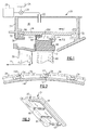
- FIG. 1 A portion of a turbine section 20 of a gas turbine engine is illustrated in Figure 1 .
- An air inlet 22 communicates with a valve 24.
- the valve 24 is controlled by a control 26.
- the control 26 controls the valve 24 to supply high pressure air such as from a compressor 28 which is part of the gas turbine engine through the valve 24, the air inlet 22, and into a pressure chamber 30.
- the pressure chamber 30 is defined by a housing 31 having static mounts 32 holding a flex beam 34.
- the flex beam 34 is formed of an appropriate material and is formed to be thin enough such that it can flex radially inwardly and outwardly.
- the housing 31 can be formed by plural housing portions.
- the flex beam should be designed for repeated flexure operation and formed of an appropriate material that is able to retain reliable spring deflection characteristics in a high temperature environment, and have consistent spring deflection characteristics over a wide temperature range.
- the flex beam is relatively thin. As one example only, it may be on the order of 0.030 in - 0.050 in (0.762 mm - 1.27 mm). The thickness of the beam is shown exaggerated in the Figures, as the beam would be so thin as to be hard to see if illustrated proportionally. In addition, as is clear from the Figures, the beam may have a relatively thinner portion aligned with the space 300, which will be described below.
- the flex beam 34 is not fixed within channels defined by the static mounts 32, but rather supported there. Seals 36 are placed in a slot 56 in the flex beam to provide a seal at the location. Wire seals are shown although other seal configurations could be used. Blade outer air seal mounts 44 and 48 on the flex beam secure hooks 50 on a blade outer air seal 42. The blade outer air seal 42 is removable from the flex beam 34 for service and repair. The blade outer air seal 42 is shown schematically. The blade outer air seal has an inner peripheral surface closely spaced from an outer tip of an airfoil of a rotor blade 40. A vane 38 is positioned upstream of the blade 40.
- pressurized air may be delivered into the pressure chamber 30.
- the opposed side of the flex beam from the pressure chamber 30 is exposed to lower pressure air.
- the delivery of the high pressure air into pressure chamber 30 will flex the flex beam 34 downwardly, such that the blade outer air seal 42 approaches the blade 40, and the clearance is reduced.
- applying a lower pressure air to the opposed side will flex the beam upwardly, such that the blade outer air seal 42 is moved away from the blade 40, and the clearance is increased.
- the control 26 can take in information about a variety of engine characteristics, and determine the amount of pressure to be delivered into the pressure chamber 30 to achieve a desired clearance. These aspects of the invention are generally as known. That is, the amount of clearance desirable would be as known, but the way of achieving the desired clearance is inventive here.
- Known electronic controls can be utilized.
- other type controllers such as, for example, a pneumatic controller, may be utilized.
- FIG 2 shows that the flex beams 34 are positioned adjacent to each other in a circumferential direction about a center axis X (see Figure 1 ) of rotation of the blade 40.
- Each flex beam 34 has one circumferential edge 52 and an opposed circumferential edge 150.
- the seal 54 is received in a slot 56 at the edge 150.
- Figure 3 shows the flex beam 34 having the slot 56 which includes side slot portions 58 and 60.
- the seal 54 may be c-shaped and positioned within the slot 56, 58,60.
- Figure 4 shows another embodiment 100 having a blade 146, vane 148, and blade outer air seal 140.
- the blade outer air seal 140 has hooks 142 and 144 associated with blade outer air seal mounts 136 and 138 defining channels in a flex beam 134.
- One edge 150 of the flex beam is received on a static mount 152 of a housing 110. As can be appreciated, there is clearance at this interface such that the flex beam can move to the right or left in this Figure.
- the opposed end 156 of the flex beam has a surface 161 in contact with an inner surface of the housing 110.
- the opposed end 156 is fixed to move with a portion 158, which is in contact with a seal 160 in a housing channel 162.
- This two-bar connection guides the flex beam 134 for movement such that it maintains the blade outer air seal 140 in a proper orientation relative to the blade 146 even when it flexes.
- FIG. 3 there is a space 300 formed between the flex beams 34 or 134 and their associated blade outer air seals 42 or 140.
- the space 300 facilitates the radially inward flexing of the flex beam 34, 134, which might otherwise be less pronounced if there was contact between the blade outer air seal 42, 140 and the flex beam 34,134 at that location.
Landscapes
- Engineering & Computer Science (AREA)
- Mechanical Engineering (AREA)
- General Engineering & Computer Science (AREA)
- Turbine Rotor Nozzle Sealing (AREA)
Abstract
Description
- Gas turbine engines are known and typically include a compressor delivering compressed gas into a combustion chamber. The compressed air is mixed with fuel and combusted in the combustion chamber. The hot products of combustion pass downstream over turbine rotors, driving the rotors to create power.
- In the design of gas turbine rotors, it is desired to ensure that the bulk of the products of combustion pass across the turbine rotors. Thus, blade outer air seals are typically placed radially outwardly of the radially outermost tip of the airfoil on turbine blades associated with the rotors.
- The clearance between the blade outer air seal and the tip of the airfoil is desirably tightly controlled. However, various factors raise challenges with maintaining this clearance. In the past, various ways for adjusting this clearance such as the use of thermal control methods have been proposed.
- In a described construction, a turbine section includes a housing and a blade outer air seal to be mounted on the housing. A flexible beam member enables mounting of the blade outer air seal onto the housing, with the flex beam being supported on the housing, but free to move relative to the housing. A pressure air chamber is formed on an opposed side of the flex beam from the blade outer air seal. A source of pressurized air is delivered into the chamber to cause the flex beam to move the blade outer air seal toward and away from a central axis of the housing.
- These and other features of the present invention can be best understood from the following specification and drawings, the following of which is a brief description.
-
-
Figure 1 is a cross-sectional view through a first embodiment. -
Figure 2 is a view along line 2-2 as shown inFigure 1 . -
Figure 3 shows a perspective view of a component. -
Figure 4 shows a second embodiment. - A portion of a
turbine section 20 of a gas turbine engine is illustrated inFigure 1 . Anair inlet 22 communicates with avalve 24. Thevalve 24 is controlled by acontrol 26. Thecontrol 26 controls thevalve 24 to supply high pressure air such as from acompressor 28 which is part of the gas turbine engine through thevalve 24, theair inlet 22, and into apressure chamber 30. Thepressure chamber 30 is defined by ahousing 31 havingstatic mounts 32 holding aflex beam 34. Theflex beam 34 is formed of an appropriate material and is formed to be thin enough such that it can flex radially inwardly and outwardly. Of course, thehousing 31 can be formed by plural housing portions. - The flex beam should be designed for repeated flexure operation and formed of an appropriate material that is able to retain reliable spring deflection characteristics in a high temperature environment, and have consistent spring deflection characteristics over a wide temperature range.
- The flex beam is relatively thin. As one example only, it may be on the order of 0.030 in - 0.050 in (0.762 mm - 1.27 mm). The thickness of the beam is shown exaggerated in the Figures, as the beam would be so thin as to be hard to see if illustrated proportionally. In addition, as is clear from the Figures, the beam may have a relatively thinner portion aligned with the
space 300, which will be described below. - The
flex beam 34 is not fixed within channels defined by thestatic mounts 32, but rather supported there.Seals 36 are placed in aslot 56 in the flex beam to provide a seal at the location. Wire seals are shown although other seal configurations could be used. Blade outerair seal mounts secure hooks 50 on a bladeouter air seal 42. The bladeouter air seal 42 is removable from theflex beam 34 for service and repair. The bladeouter air seal 42 is shown schematically. The blade outer air seal has an inner peripheral surface closely spaced from an outer tip of an airfoil of arotor blade 40. Avane 38 is positioned upstream of theblade 40. - During operation of the gas turbine engine, pressurized air may be delivered into the
pressure chamber 30. The opposed side of the flex beam from thepressure chamber 30 is exposed to lower pressure air. Thus, the delivery of the high pressure air intopressure chamber 30 will flex theflex beam 34 downwardly, such that the bladeouter air seal 42 approaches theblade 40, and the clearance is reduced. Additionally, applying a lower pressure air to the opposed side will flex the beam upwardly, such that the bladeouter air seal 42 is moved away from theblade 40, and the clearance is increased. - The
control 26 can take in information about a variety of engine characteristics, and determine the amount of pressure to be delivered into thepressure chamber 30 to achieve a desired clearance. These aspects of the invention are generally as known. That is, the amount of clearance desirable would be as known, but the way of achieving the desired clearance is inventive here. Known electronic controls can be utilized. On the other hand, other type controllers, such as, for example, a pneumatic controller, may be utilized. -
Figure 2 shows that theflex beams 34 are positioned adjacent to each other in a circumferential direction about a center axis X (seeFigure 1 ) of rotation of theblade 40. Eachflex beam 34 has onecircumferential edge 52 and an opposedcircumferential edge 150. Theseal 54 is received in aslot 56 at theedge 150. -
Figure 3 shows theflex beam 34 having theslot 56 which includesside slot portions seal 54 may be c-shaped and positioned within theslot -
Figure 4 shows anotherembodiment 100 having ablade 146,vane 148, and bladeouter air seal 140. The bladeouter air seal 140 hashooks air seal mounts flex beam 134. Oneedge 150 of the flex beam is received on astatic mount 152 of ahousing 110. As can be appreciated, there is clearance at this interface such that the flex beam can move to the right or left in this Figure. - The opposed
end 156 of the flex beam has asurface 161 in contact with an inner surface of thehousing 110. Theopposed end 156 is fixed to move with aportion 158, which is in contact with aseal 160 in ahousing channel 162. This two-bar connection guides theflex beam 134 for movement such that it maintains the bladeouter air seal 140 in a proper orientation relative to theblade 146 even when it flexes. - As can be appreciated from both
Figures 1 and4 , there is aspace 300 formed between theflex beams outer air seals space 300 facilitates the radially inward flexing of theflex beam outer air seal - Although embodiments of this invention have been disclosed, a worker of ordinary skill in this art would recognize that certain modifications would come within the scope of this invention. For that reason, the following claims should be studied to determine the true scope and content of this invention.
Claims (13)
- A housing section for a gas turbine engine comprising:a housing (31;110);a flex beam (34;134) mounting a blade outer air seal (42;140) onto said housing (31;110), with said flex beam (34;134) being supported on said housing (31; 110), and free to move relative to said housing; anda pressure chamber (30) formed on an opposed side of said flex beam (34;134) from said blade outer air seal (42;140), and a source of pressurized air to be delivered into said pressure chamber (30) to cause said flex beam (34;134) to move said blade outer air seal (42;140) toward and away from a central axis of said housing (31;110).
- The housing as set forth in claim 1, wherein said source of pressurized air includes a valve (24) controlled by a controller (26) to control the pressure of air delivered into said pressure chamber (30).
- The housing as set forth in claim 1 or 2, wherein said flex beam (34;134) is supported within said housing at axially upstream and downstream ends, but free to move in an axial direction.
- The housing as set forth in claim 3, wherein a seal (36;160) is positioned between said flex beam (34;134) and said housing (31;110).
- The housing as set forth in claim 4, wherein said seal (36) on said flex beam (34) extends along at least one axial side of said flex beam (34), and at leat a portion of two circumferential edges.
- The housing as set forth in any preceding claim, wherein said flex beam (34;134) removably mounts said blade outer air seal (42;140).
- The housing as set forth in any preceding claim, wherein said flex beam includes a two-bar connection which guides said flex beam during flexing movement relative to said housing.
- The housing as set forth in any preceding claim, wherein there are a plurality of adjacent flex beam portions (34;134) extending over a portion of a circumferential extent of the housing (31;110).
- The housing as set forth in claim 8, wherein each of said flex beam portions (34) have opposed circumferential edges (52) that interfit with an adjacent one of said flex beams (34), and a seal (54) positioned between said circumferential edges.
- The housing as set forth in any preceding claim, wherein said housing (31;110) is utilized as part of a turbine section in a gas turbine engine.
- The housing as set forth in any preceding claim, wherein a space (300) is defined radially between a side of said flex beam (34;134) which faces said blade outer air seal (42;140), and a radially outer portion of said blade outer air seal (42;140) to facilitate radially inward flexing of the flex beam (34;134).
- The housing as set forth in claim 11, wherein said flex beam (34;134) is relatively thin at least in an area aligned with said space (300), and between 0.030 - 0.050 inches (0.762 - 1.27 mm).
- A turbine section for a gas turbine engine comprising:a turbine rotor carrying a plurality of blades (40;146), said blades having a radial outer tip;a housing section as set forth in any preceding claim.
Applications Claiming Priority (1)
| Application Number | Priority Date | Filing Date | Title |
|---|---|---|---|
| US12/791,056 US20110293407A1 (en) | 2010-06-01 | 2010-06-01 | Seal and airfoil tip clearance control |
Publications (2)
| Publication Number | Publication Date |
|---|---|
| EP2392780A2 true EP2392780A2 (en) | 2011-12-07 |
| EP2392780A3 EP2392780A3 (en) | 2014-11-05 |
Family
ID=44118077
Family Applications (1)
| Application Number | Title | Priority Date | Filing Date |
|---|---|---|---|
| EP11168277.9A Withdrawn EP2392780A3 (en) | 2010-06-01 | 2011-05-31 | Seal and airfoil tip clearance control |
Country Status (2)
| Country | Link |
|---|---|
| US (1) | US20110293407A1 (en) |
| EP (1) | EP2392780A3 (en) |
Cited By (1)
| Publication number | Priority date | Publication date | Assignee | Title |
|---|---|---|---|---|
| WO2014052345A1 (en) * | 2012-09-27 | 2014-04-03 | United Technologies Corporation | Full ring inner air-seal with locking nut |
Families Citing this family (5)
| Publication number | Priority date | Publication date | Assignee | Title |
|---|---|---|---|---|
| US8961115B2 (en) * | 2012-07-19 | 2015-02-24 | United Technologies Corporation | Clearance control for gas turbine engine seal |
| US9255524B2 (en) | 2012-12-20 | 2016-02-09 | United Technologies Corporation | Variable outer air seal fluid control |
| WO2014186015A2 (en) * | 2013-03-11 | 2014-11-20 | United Technologies Corporation | Actuator for gas turbine engine blade outer air seal |
| US10557368B2 (en) | 2013-04-12 | 2020-02-11 | United Technologies Corporation | Gas turbine engine rapid response clearance control system with variable volume turbine case |
| US11248485B1 (en) | 2020-08-17 | 2022-02-15 | General Electric Company | Systems and apparatus to control deflection mismatch between static and rotating structures |
Family Cites Families (7)
| Publication number | Priority date | Publication date | Assignee | Title |
|---|---|---|---|---|
| GB2195715B (en) * | 1986-10-08 | 1990-10-10 | Rolls Royce Plc | Gas turbine engine rotor blade clearance control |
| US5344284A (en) * | 1993-03-29 | 1994-09-06 | The United States Of America As Represented By The Secretary Of The Air Force | Adjustable clearance control for rotor blade tips in a gas turbine engine |
| GB2310255B (en) * | 1996-02-13 | 1999-06-16 | Rolls Royce Plc | A turbomachine |
| GB2388407B (en) * | 2002-05-10 | 2005-10-26 | Rolls Royce Plc | Gas turbine blade tip clearance control structure |
| GB2404953A (en) * | 2003-08-15 | 2005-02-16 | Rolls Royce Plc | Blade tip clearance system |
| FR2906295B1 (en) * | 2006-09-22 | 2011-11-18 | Snecma | DEVICE FOR INSULATING SHEETS ON A CARTER FOR IMPROVING THE GAME IN A DAWN TOP |
| US8268032B2 (en) * | 2008-07-07 | 2012-09-18 | General Electric Company | Gasket for providing a seal between two objects |
-
2010
- 2010-06-01 US US12/791,056 patent/US20110293407A1/en not_active Abandoned
-
2011
- 2011-05-31 EP EP11168277.9A patent/EP2392780A3/en not_active Withdrawn
Non-Patent Citations (1)
| Title |
|---|
| None |
Cited By (2)
| Publication number | Priority date | Publication date | Assignee | Title |
|---|---|---|---|---|
| WO2014052345A1 (en) * | 2012-09-27 | 2014-04-03 | United Technologies Corporation | Full ring inner air-seal with locking nut |
| US9327368B2 (en) | 2012-09-27 | 2016-05-03 | United Technologies Corporation | Full ring inner air-seal with locking nut |
Also Published As
| Publication number | Publication date |
|---|---|
| EP2392780A3 (en) | 2014-11-05 |
| US20110293407A1 (en) | 2011-12-01 |
Similar Documents
| Publication | Publication Date | Title |
|---|---|---|
| EP2392780A2 (en) | Seal and airfoil tip clearance control | |
| EP2546469B1 (en) | Blade outer air seal assembly | |
| EP2479385B1 (en) | Blade outer air seal assembly | |
| US8459944B2 (en) | Stator blade ring and axial flow compressor using the same | |
| EP3073055B1 (en) | Damper for stator assembly and stator assembly | |
| KR101409128B1 (en) | Stator vane spring damper | |
| EP1942252B1 (en) | Airfoil tip for a rotor assembly | |
| EP2961941B1 (en) | Apparatuses comprising a pivotable turbine vane | |
| EP2620599A2 (en) | Turbomachine with an angled abradable interstage seal and corresponding method of reducing a seal gap | |
| EP3680521B1 (en) | Hydrostatic seal with aft tooth | |
| EP2559858B1 (en) | Compressors with integrated secondary air flow systems | |
| JP2008509369A (en) | Leaf seal device | |
| EP3029278A1 (en) | Blade outer air seal support structure | |
| US9677669B2 (en) | Shaft seal device and rotary machine | |
| US9909435B2 (en) | Turbine engine variable area vane with feather seal | |
| CN101988392A (en) | Rotor blades for turbine engines | |
| WO2011038971A1 (en) | Airfoil and corresponding guide vane, blade, gas turbine and turbomaschine | |
| JP2009243685A (en) | Leaf seal for turbo-machine | |
| EP3118414B1 (en) | Gas turbine engine airfoil | |
| EP1918523B1 (en) | Rotor blade and corresponding turbine engine | |
| EP3453838A1 (en) | Contacting dry face seal with tapered carbon nose | |
| US7654791B2 (en) | Apparatus and method for controlling a blade tip clearance for a compressor | |
| EP2636852B1 (en) | Hybrid inner air seal for gas turbine engines | |
| US10934846B2 (en) | Turbine rotor comprising a ventilation spacer | |
| EP4671513A2 (en) | TURBINE ARRANGEMENT FOR A TURBOCHARGER |
Legal Events
| Date | Code | Title | Description |
|---|---|---|---|
| AK | Designated contracting states |
Kind code of ref document: A2 Designated state(s): AL AT BE BG CH CY CZ DE DK EE ES FI FR GB GR HR HU IE IS IT LI LT LU LV MC MK MT NL NO PL PT RO RS SE SI SK SM TR |
|
| AX | Request for extension of the european patent |
Extension state: BA ME |
|
| PUAI | Public reference made under article 153(3) epc to a published international application that has entered the european phase |
Free format text: ORIGINAL CODE: 0009012 |
|
| PUAL | Search report despatched |
Free format text: ORIGINAL CODE: 0009013 |
|
| AK | Designated contracting states |
Kind code of ref document: A3 Designated state(s): AL AT BE BG CH CY CZ DE DK EE ES FI FR GB GR HR HU IE IS IT LI LT LU LV MC MK MT NL NO PL PT RO RS SE SI SK SM TR |
|
| AX | Request for extension of the european patent |
Extension state: BA ME |
|
| RIC1 | Information provided on ipc code assigned before grant |
Ipc: F01D 11/22 20060101AFI20140930BHEP |
|
| STAA | Information on the status of an ep patent application or granted ep patent |
Free format text: STATUS: THE APPLICATION IS DEEMED TO BE WITHDRAWN |
|
| 18D | Application deemed to be withdrawn |
Effective date: 20150507 |