EP2392778A2 - Composite gas turbine engine component - Google Patents
Composite gas turbine engine component Download PDFInfo
- Publication number
- EP2392778A2 EP2392778A2 EP11250582A EP11250582A EP2392778A2 EP 2392778 A2 EP2392778 A2 EP 2392778A2 EP 11250582 A EP11250582 A EP 11250582A EP 11250582 A EP11250582 A EP 11250582A EP 2392778 A2 EP2392778 A2 EP 2392778A2
- Authority
- EP
- European Patent Office
- Prior art keywords
- gas turbine
- turbine engine
- ply
- shroud
- airfoil
- Prior art date
- Legal status (The legal status is an assumption and is not a legal conclusion. Google has not performed a legal analysis and makes no representation as to the accuracy of the status listed.)
- Withdrawn
Links
- 239000002131 composite material Substances 0.000 title claims abstract description 36
- 239000000835 fiber Substances 0.000 claims abstract description 25
- 238000010276 construction Methods 0.000 claims abstract description 24
- 238000007789 sealing Methods 0.000 claims abstract description 20
- 238000000034 method Methods 0.000 claims abstract description 15
- 239000000463 material Substances 0.000 claims abstract description 6
- 239000011159 matrix material Substances 0.000 claims description 15
- 239000011153 ceramic matrix composite Substances 0.000 claims description 6
- 230000008878 coupling Effects 0.000 claims description 4
- 238000010168 coupling process Methods 0.000 claims description 4
- 238000005859 coupling reaction Methods 0.000 claims description 4
- 239000000945 filler Substances 0.000 abstract description 4
- 230000008901 benefit Effects 0.000 description 2
- 238000004519 manufacturing process Methods 0.000 description 2
- 238000012986 modification Methods 0.000 description 2
- 230000004048 modification Effects 0.000 description 2
- 206010003402 Arthropod sting Diseases 0.000 description 1
- 230000004075 alteration Effects 0.000 description 1
- 238000005229 chemical vapour deposition Methods 0.000 description 1
- 230000007123 defense Effects 0.000 description 1
- 238000005516 engineering process Methods 0.000 description 1
- 239000000446 fuel Substances 0.000 description 1
- 235000012149 noodles Nutrition 0.000 description 1
- 238000010248 power generation Methods 0.000 description 1
- 230000008569 process Effects 0.000 description 1
- 230000001737 promoting effect Effects 0.000 description 1
- 238000005086 pumping Methods 0.000 description 1
- 239000000126 substance Substances 0.000 description 1
Images

Classifications
-
- F—MECHANICAL ENGINEERING; LIGHTING; HEATING; WEAPONS; BLASTING
- F01—MACHINES OR ENGINES IN GENERAL; ENGINE PLANTS IN GENERAL; STEAM ENGINES
- F01D—NON-POSITIVE DISPLACEMENT MACHINES OR ENGINES, e.g. STEAM TURBINES
- F01D5/00—Blades; Blade-carrying members; Heating, heat-insulating, cooling or antivibration means on the blades or the members
- F01D5/12—Blades
- F01D5/28—Selecting particular materials; Particular measures relating thereto; Measures against erosion or corrosion
- F01D5/282—Selecting composite materials, e.g. blades with reinforcing filaments
-
- F—MECHANICAL ENGINEERING; LIGHTING; HEATING; WEAPONS; BLASTING
- F01—MACHINES OR ENGINES IN GENERAL; ENGINE PLANTS IN GENERAL; STEAM ENGINES
- F01D—NON-POSITIVE DISPLACEMENT MACHINES OR ENGINES, e.g. STEAM TURBINES
- F01D5/00—Blades; Blade-carrying members; Heating, heat-insulating, cooling or antivibration means on the blades or the members
- F01D5/12—Blades
- F01D5/14—Form or construction
- F01D5/147—Construction, i.e. structural features, e.g. of weight-saving hollow blades
-
- F—MECHANICAL ENGINEERING; LIGHTING; HEATING; WEAPONS; BLASTING
- F01—MACHINES OR ENGINES IN GENERAL; ENGINE PLANTS IN GENERAL; STEAM ENGINES
- F01D—NON-POSITIVE DISPLACEMENT MACHINES OR ENGINES, e.g. STEAM TURBINES
- F01D5/00—Blades; Blade-carrying members; Heating, heat-insulating, cooling or antivibration means on the blades or the members
- F01D5/12—Blades
- F01D5/22—Blade-to-blade connections, e.g. for damping vibrations
- F01D5/225—Blade-to-blade connections, e.g. for damping vibrations by shrouding
-
- F—MECHANICAL ENGINEERING; LIGHTING; HEATING; WEAPONS; BLASTING
- F01—MACHINES OR ENGINES IN GENERAL; ENGINE PLANTS IN GENERAL; STEAM ENGINES
- F01D—NON-POSITIVE DISPLACEMENT MACHINES OR ENGINES, e.g. STEAM TURBINES
- F01D5/00—Blades; Blade-carrying members; Heating, heat-insulating, cooling or antivibration means on the blades or the members
- F01D5/12—Blades
- F01D5/28—Selecting particular materials; Particular measures relating thereto; Measures against erosion or corrosion
- F01D5/284—Selection of ceramic materials
-
- F—MECHANICAL ENGINEERING; LIGHTING; HEATING; WEAPONS; BLASTING
- F05—INDEXING SCHEMES RELATING TO ENGINES OR PUMPS IN VARIOUS SUBCLASSES OF CLASSES F01-F04
- F05D—INDEXING SCHEME FOR ASPECTS RELATING TO NON-POSITIVE-DISPLACEMENT MACHINES OR ENGINES, GAS-TURBINES OR JET-PROPULSION PLANTS
- F05D2300/00—Materials; Properties thereof
- F05D2300/60—Properties or characteristics given to material by treatment or manufacturing
- F05D2300/603—Composites; e.g. fibre-reinforced
- F05D2300/6033—Ceramic matrix composites [CMC]
-
- Y—GENERAL TAGGING OF NEW TECHNOLOGICAL DEVELOPMENTS; GENERAL TAGGING OF CROSS-SECTIONAL TECHNOLOGIES SPANNING OVER SEVERAL SECTIONS OF THE IPC; TECHNICAL SUBJECTS COVERED BY FORMER USPC CROSS-REFERENCE ART COLLECTIONS [XRACs] AND DIGESTS
- Y02—TECHNOLOGIES OR APPLICATIONS FOR MITIGATION OR ADAPTATION AGAINST CLIMATE CHANGE
- Y02T—CLIMATE CHANGE MITIGATION TECHNOLOGIES RELATED TO TRANSPORTATION
- Y02T50/00—Aeronautics or air transport
- Y02T50/60—Efficient propulsion technologies, e.g. for aircraft
-
- Y—GENERAL TAGGING OF NEW TECHNOLOGICAL DEVELOPMENTS; GENERAL TAGGING OF CROSS-SECTIONAL TECHNOLOGIES SPANNING OVER SEVERAL SECTIONS OF THE IPC; TECHNICAL SUBJECTS COVERED BY FORMER USPC CROSS-REFERENCE ART COLLECTIONS [XRACs] AND DIGESTS
- Y10—TECHNICAL SUBJECTS COVERED BY FORMER USPC
- Y10T—TECHNICAL SUBJECTS COVERED BY FORMER US CLASSIFICATION
- Y10T156/00—Adhesive bonding and miscellaneous chemical manufacture
- Y10T156/10—Methods of surface bonding and/or assembly therefor
- Y10T156/1002—Methods of surface bonding and/or assembly therefor with permanent bending or reshaping or surface deformation of self sustaining lamina
- Y10T156/1026—Methods of surface bonding and/or assembly therefor with permanent bending or reshaping or surface deformation of self sustaining lamina with slitting or removal of material at reshaping area prior to reshaping
-
- Y—GENERAL TAGGING OF NEW TECHNOLOGICAL DEVELOPMENTS; GENERAL TAGGING OF CROSS-SECTIONAL TECHNOLOGIES SPANNING OVER SEVERAL SECTIONS OF THE IPC; TECHNICAL SUBJECTS COVERED BY FORMER USPC CROSS-REFERENCE ART COLLECTIONS [XRACs] AND DIGESTS
- Y10—TECHNICAL SUBJECTS COVERED BY FORMER USPC
- Y10T—TECHNICAL SUBJECTS COVERED BY FORMER US CLASSIFICATION
- Y10T156/00—Adhesive bonding and miscellaneous chemical manufacture
- Y10T156/10—Methods of surface bonding and/or assembly therefor
- Y10T156/1002—Methods of surface bonding and/or assembly therefor with permanent bending or reshaping or surface deformation of self sustaining lamina
- Y10T156/1028—Methods of surface bonding and/or assembly therefor with permanent bending or reshaping or surface deformation of self sustaining lamina by bending, drawing or stretch forming sheet to assume shape of configured lamina while in contact therewith
Definitions
- the present invention generally relates to gas turbine engine components, and more particularly, but not exclusively, to gas turbine engine turbomachinery components.
- a first aspect of the present invention provides an apparatus composing: a gas turbine engine airflow member having an airfoil portion and a shroud portion and constructed from a composite material construction including a matrix and a plurality of fiber plies, at least one of the fiber plies extending from the airfoil portion to the shroud portion.
- the composite material construction may be a CMC.
- the gas turbine engine airflow member may be integrated within a component of a gas turbine engine.
- the component is preferably a hot section component.
- the plurality of fiber plies may include two dimensional orientation.
- the gas turbine engine airflow member preferably includes a sealing knife coupled to the end of the member, a plurality of stitches affixing the seating knife to the tip shroud.
- the plurality of fiber plies may include three dimensional orientation.
- the plurality of fiber plies may include at least one fiber ply that has been darted.
- a second aspect of the present invention provides an apparatus comprising: a gas turbine engine turbomachinery component having a plurality of airfoil members capable of directing a flow stream through the component, each of the plurality of airfoil members made from a composite material and having a tip shroud integral with a portion of the airfoil member extending from a hub of the gas turbine engine turbomachinery component.
- the plurality of airfoil members may include integral sealing knifes.
- the integral sealing knifes may each include a plurality of sealing knifes.
- the plurality of sealing knifes preferably including opposing L shapes and an intermediate U shape.
- the integral sealing knifes may each include a composite ply separate from, a composite ply of the plurality of airfoil members.
- the composite material may be a ceramic matrix composite material.
- a third aspect of the present invention provides an apparatus comprising: a gas turbine engine rotatable blade having an airfoil part and a shroud disposed at an end of the blade, the blade made of a composite construction having a ply and a matrix; and means for forming the shroud from a ply of the airfoil part.
- a fourth aspect of the present invention provides a method comprising: engaging a ply of a composite construction with a device that forms a blade shape of a gas turbine engine component; laying up the ply such that the ply extends from an airfoil part of the blade shape and continues to a shroud part of the blade shape; and coupling a plurality of plies of the blade shape with a matrix material to form the composite construction.
- the laying up may include darting the ply.
- the method may further include laying up a plurality of plies to create the shroud part.
- the method may further include forming a sealing knife portion with a separate ply and stitching the separate ply to the shroud part.
- the method may further include stitching the ply of the shroud part to a ply of a sealing knife.
- One embodiment of the present invention is a unique gas turbine engine component having a composite construction.
- Other embodiments include apparatuses, systems, devices, hardware, methods, and combinations for forming composite gas turbine engine blades. Further embodiments, forms, features, aspects, benefits, and advantages of the present application shall become apparent from the description and figures provided herewith.
- a gas turbine engine 50 having a compressor 52, combustor 54, and turbine 56. Air is provided to the compressor 52 whereupon it is compressed and provided to the combustor 54. Fuel is mixed with the compressed air and burned and then provided to the turbine 56.
- the gas turbine engine 50 is depicted as a single spool engine, in other embodiments the gas turbine engine 50 can have multiple spools.
- the gas turbine engine 50 can be used in various applications and can take a variety of forms. To set forth just a few non-limiting examples, the gas turbine engine can take the form of a turbofan, turbojet, turboprop, or turboshaft engine. In one application the gas turbine engine can be used as an aircraft powerplant.
- aircraft includes, but is not limited to, helicopters, airplanes, unmanned space vehicles, fixed wing vehicles, variable wing vehicles, rotary wing vehicles, unmanned combat aerial vehicles, tailless aircraft, hover crafts, and other airborne and/or extraterrestrial (spacecraft) vehicles.
- helicopters airplanes
- unmanned space vehicles fixed wing vehicles
- variable wing vehicles variable wing vehicles
- rotary wing vehicles unmanned combat aerial vehicles
- tailless aircraft hover crafts
- helicopters airborne and/or extraterrestrial (spacecraft) vehicles.
- present inventions are contemplated for utilization in other applications that may not be coupled with an aircraft such as, for example, Industrial applications, power generation, pumping sets, naval propulsion, weapon systems, security systems, perimeter defense/security systems, and the like known to one of ordinary skill in the art.
- a portion of a gas turbine engine component 58 is shown having the shape of a blade useful within a turbomachinery component of the gas turbine engine 50,
- the gas turbine engine component 58 is used within the turbine 56 (shown in Fig. 1 ) of the gas turbine engine 50.
- the gas turbine engine component 58 can take other forms for use in various portions of the gas turbine engine 50.
- the gas turbine engine component 58 is made from a composite construction that includes a matrix and one or more plies that include a plurality of fibers.
- the gas turbine engine component 58 is made from a ceramic matrix composite (CMC), but other types of composites are also contemplated herein.
- CMC ceramic matrix composite
- the matrix that composes the CMC composite can be applied in a variety of ways, including single step, two step, or multiple steps.
- the matrix can be deposited via chemical vapor deposition among other possible techniques.
- the fibers that make up the plies of the composite construction can be various denier and the plies can have various thread count
- the fibers can be unidirectional or cross plied, as well as any other orientation.
- the plies can be any architecture, including 2D or 3D, tape, woven, etc. In some forms, such as some 2D architectures, adjacent plies can be stitched together to maintain a shape during processing.
- the gas turbine engine component 58 includes an extension 60 oriented transverse to an elongate portion of the gas turbine engine component 58, which in the illustrative embodiment the elongate portion is an airfoil member portion 62 forming part of the blade.
- the extension 60 takes the form of a blade shroud.
- the extension 60 is formed when one or more plies used in the airfoil member portion 62 are turned to create the extension 60. In this way a plurality of fibers that form part of the airfoil member portion 62 also create the extension 60.
- the plies that form the extension 60 need not extend from the root of the gas turbine engine component 58 to its tip.
- the extensions 60 can have multiple sections of plies oriented in the same or even different directions.
- the extension 60 can additionally include one or more fiber plies that do not otherwise extend into the airfoil member portion 62 such that the additional plies reside primarily in the extension 60.
- the extension 60 can include multiple plies that are stitched together.
- the gas turbine engine component 58 can be a continuous wrap ply or can be created by individual plies. In some applications, one or more plies can be darted to create the extension 60. Depending on the application, other techniques such as, but not limited to, pleats and gussets can be used with respect to the extension 60 and/or any other portion of the gas turbine engine component 58.
- the gas turbine engine component 58 can also include extension members 64 having a portion generally oriented along the elongate portion of the gas turbine engine component 58. In some embodiments of the gas turbine engine component 58, however, the extension members 64 may not be present. In the illustrative form the extension members 64 take the form of sealing knives that can be used with a device or structure formed in or coupled to a casing of the gas turbine engine 50. Though there are three extension members 64 depicted in Fig. 1 , fewer or more can be present in other embodiments. The extension members 64 have a variety of non-limiting forms in the illustrative embodiment. Two L-shaped extension members 64 sit on opposite sides of a U-shaped extension member 64. Each of the extension members 64 depicted in Fig.
- extension members 64 can be either in direct contact with the end portion of the gas turbine engine component 58, or an intermediate structure or material can be disposed between the two.
- the individual plies of either or both the extension 60 and the extension members 64 can be coupled together, such as through stitching 66.
- the extension 60 can be stitched to one or more of the extension members 64.
- the extension members 64 can be stitched together in their upturned portions.
- Filler can be used in select areas of the gas turbine engine component 58, and in some cases can be used between fiber plies when the orientation of the plies creates voids.
- a fiber "noodle" or collection of tow, or both can be used.
- Such fillers can be placed, for example, between the upturned legs of the plies of the extension members 64, between the plies of the extension member 64 and the plies of the airfoil member portion 62, and additionally and/or alternatively near the tip of the gas turbine engine component 58 between the extensions 60 that define the shape of the airfoil member portion 62.
- Other locations are also contemplated herein.
- the tow can be crimped or it can be uncrimped, and it can have various lengths and a variety of denier.
- multiple plies of the composite construction are collated together to a certain thickness and can be formed to a desired shape.
- the plies can be collated on tooling, such as a mold or a mandrel, among others, to define the shape, or near shape, of the desired component.
- tooling such as a mold or a mandrel, among others.
- the composite construction can be rigidized while coupled with the tooling and prior to the introduction of the matrix. Rigidization can occur when fibers are bonded with a bonding material at points of contact. In some forms the bonding material can thoroughly coat the fibers.
- the intermediate form can be further processed by removing the mandrel, mold or other tooling.
- the mandrel can be removed by physical, chemical, or thermal processes, among others, In any event, a matrix is provided to infiltrate between the plies and fibers to form the composite construction.
- Fig. 3 one embodiment of the gas turbine engine component 58 is shown having the extension 60 and extension members 64.
- the plies are depicted as solid lines where each of the extension members 64 includes two plies and the extension includes two plies. Stiches 66 are shown coupling the upturned portions of the extension members 64 and extension 60. Also shown in Fig. 3 is a filler 68 disposed in an area between the extension 60 and the extension members 64.
- One aspect of the present application provides an apparatus comprising a gas turbine engine airflow member having an airfoil portion and a shroud portion and constructed from a composite material construction including a matrix and a plurality of fiber plies, at least one of the fiber plies extending from the airfoil portion to the shroud portion.
- Another aspect of the present application provides an apparatus comprising a gas turbine engine turbomachinery component having a plurality of airfoil members capable of directing a flow stream through the component, each of the plurality of airfoil members made from a composite material and having a tip shroud integral with a portion of the airfoil member extending from a hub of the gas turbine engine turbomachinery component.
- Still another aspect of the present application provides an apparatus comprising a gas turbine engine rotatable blade having an airfoil part and a shroud disposed at an end of the blade, the blade made of a composite construction having a ply and a matrix, and means for forming the shroud from a ply of the airfoil part.
- Yet still another aspect of the present application provides a method comprising engaging a ply of a composite construction with a device that forms a blade shape of a gas turbine engine component, laying up the ply such that the ply extends from an airfoil part of the blade shape and continues to a shroud part of the blade shape, and coupling a plurality of plies of the blade shape with a matrix material to form the composite construction.
Landscapes
- Engineering & Computer Science (AREA)
- Chemical & Material Sciences (AREA)
- Mechanical Engineering (AREA)
- General Engineering & Computer Science (AREA)
- Materials Engineering (AREA)
- Ceramic Engineering (AREA)
- Composite Materials (AREA)
- Architecture (AREA)
- Turbine Rotor Nozzle Sealing (AREA)
Abstract
Description
- The present invention generally relates to gas turbine engine components, and more particularly, but not exclusively, to gas turbine engine turbomachinery components.
- Building gas turbine engine components having a composite construction remains an area of interest. Some existing systems have various shortcomings relative to certain applications. Accordingly, there remains a need for further contributions in this area of technology.
- A first aspect of the present invention provides an apparatus composing: a gas turbine engine airflow member having an airfoil portion and a shroud portion and constructed from a composite material construction including a matrix and a plurality of fiber plies, at least one of the fiber plies extending from the airfoil portion to the shroud portion.
- The composite material construction may be a CMC. The gas turbine engine airflow member may be integrated within a component of a gas turbine engine. The component is preferably a hot section component.
- The plurality of fiber plies may include two dimensional orientation. The gas turbine engine airflow member preferably includes a sealing knife coupled to the end of the member, a plurality of stitches affixing the seating knife to the tip shroud.
- The plurality of fiber plies may include three dimensional orientation.
- The plurality of fiber plies may include at least one fiber ply that has been darted.
- A second aspect of the present invention provides an apparatus comprising: a gas turbine engine turbomachinery component having a plurality of airfoil members capable of directing a flow stream through the component, each of the plurality of airfoil members made from a composite material and having a tip shroud integral with a portion of the airfoil member extending from a hub of the gas turbine engine turbomachinery component.
- The plurality of airfoil members may include integral sealing knifes.
- The integral sealing knifes may each include a plurality of sealing knifes. The plurality of sealing knifes preferably including opposing L shapes and an intermediate U shape.
- The integral sealing knifes may each include a composite ply separate from, a composite ply of the plurality of airfoil members.
- The composite material may be a ceramic matrix composite material.
- A third aspect of the present invention provides an apparatus comprising: a gas turbine engine rotatable blade having an airfoil part and a shroud disposed at an end of the blade, the blade made of a composite construction having a ply and a matrix; and means for forming the shroud from a ply of the airfoil part.
- A fourth aspect of the present invention provides a method comprising: engaging a ply of a composite construction with a device that forms a blade shape of a gas turbine engine component; laying up the ply such that the ply extends from an airfoil part of the blade shape and continues to a shroud part of the blade shape; and coupling a plurality of plies of the blade shape with a matrix material to form the composite construction.
- The laying up may include darting the ply. The method may further include laying up a plurality of plies to create the shroud part.
- The method may further include forming a sealing knife portion with a separate ply and stitching the separate ply to the shroud part.
- The method may further include stitching the ply of the shroud part to a ply of a sealing knife.
- One embodiment of the present invention is a unique gas turbine engine component having a composite construction. Other embodiments include apparatuses, systems, devices, hardware, methods, and combinations for forming composite gas turbine engine blades. Further embodiments, forms, features, aspects, benefits, and advantages of the present application shall become apparent from the description and figures provided herewith.
-
Fig. 1 depicts one embodiment of a gas turbine engine. -
Fig. 2 depicts one embodiment of a gas turbine engine component. -
Fig. 3 depicts one embodiment of a gas turbine engine component. - For the purposes of promoting an understanding of the principles of the invention, reference will now be made to the embodiments illustrated in the drawings and specific language will be used to describe the same. It will nevertheless be understood that no limitation of the scope of the invention is thereby intended. Any alterations and further modifications in the described embodiments, and any further applications of the principles of the invention as described herein are contemplated as would normally occur to one skilled in the art to which the invention relates.
- With reference to
Fig. 1 , agas turbine engine 50 is illustrated having acompressor 52,combustor 54, andturbine 56. Air is provided to thecompressor 52 whereupon it is compressed and provided to thecombustor 54. Fuel is mixed with the compressed air and burned and then provided to theturbine 56. Though thegas turbine engine 50 is depicted as a single spool engine, in other embodiments thegas turbine engine 50 can have multiple spools. Thegas turbine engine 50 can be used in various applications and can take a variety of forms. To set forth just a few non-limiting examples, the gas turbine engine can take the form of a turbofan, turbojet, turboprop, or turboshaft engine. In one application the gas turbine engine can be used as an aircraft powerplant. - As used herein, the term "aircraft" includes, but is not limited to, helicopters, airplanes, unmanned space vehicles, fixed wing vehicles, variable wing vehicles, rotary wing vehicles, unmanned combat aerial vehicles, tailless aircraft, hover crafts, and other airborne and/or extraterrestrial (spacecraft) vehicles. Further, the present inventions are contemplated for utilization in other applications that may not be coupled with an aircraft such as, for example, Industrial applications, power generation, pumping sets, naval propulsion, weapon systems, security systems, perimeter defense/security systems, and the like known to one of ordinary skill in the art.
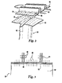
- With reference to
Fig. 2 , a portion of a gasturbine engine component 58 is shown having the shape of a blade useful within a turbomachinery component of thegas turbine engine 50, In one form the gasturbine engine component 58 is used within the turbine 56 (shown inFig. 1 ) of thegas turbine engine 50. In other embodiments the gasturbine engine component 58 can take other forms for use in various portions of thegas turbine engine 50. The gasturbine engine component 58 is made from a composite construction that includes a matrix and one or more plies that include a plurality of fibers. In one form the gasturbine engine component 58 is made from a ceramic matrix composite (CMC), but other types of composites are also contemplated herein. The matrix that composes the CMC composite can be applied in a variety of ways, including single step, two step, or multiple steps. In addition, the matrix can be deposited via chemical vapor deposition among other possible techniques. The fibers that make up the plies of the composite construction can be various denier and the plies can have various thread count In addition, the fibers can be unidirectional or cross plied, as well as any other orientation. In general the plies can be any architecture, including 2D or 3D, tape, woven, etc. In some forms, such as some 2D architectures, adjacent plies can be stitched together to maintain a shape during processing. - The gas
turbine engine component 58 includes anextension 60 oriented transverse to an elongate portion of the gasturbine engine component 58, which in the illustrative embodiment the elongate portion is anairfoil member portion 62 forming part of the blade. In the depiction inFig. 2 theextension 60 takes the form of a blade shroud. Theextension 60 is formed when one or more plies used in theairfoil member portion 62 are turned to create theextension 60. In this way a plurality of fibers that form part of theairfoil member portion 62 also create theextension 60. The plies that form theextension 60. however, need not extend from the root of the gasturbine engine component 58 to its tip. Theextensions 60 can have multiple sections of plies oriented in the same or even different directions. In some embodiments theextension 60 can additionally include one or more fiber plies that do not otherwise extend into theairfoil member portion 62 such that the additional plies reside primarily in theextension 60. In some embodiments theextension 60 can include multiple plies that are stitched together. The gasturbine engine component 58 can be a continuous wrap ply or can be created by individual plies. In some applications, one or more plies can be darted to create theextension 60. Depending on the application, other techniques such as, but not limited to, pleats and gussets can be used with respect to theextension 60 and/or any other portion of the gasturbine engine component 58. - The gas
turbine engine component 58 can also includeextension members 64 having a portion generally oriented along the elongate portion of the gasturbine engine component 58. In some embodiments of the gasturbine engine component 58, however, theextension members 64 may not be present. In the illustrative form theextension members 64 take the form of sealing knives that can be used with a device or structure formed in or coupled to a casing of thegas turbine engine 50. Though there are threeextension members 64 depicted inFig. 1 , fewer or more can be present in other embodiments. Theextension members 64 have a variety of non-limiting forms in the illustrative embodiment. Two L-shapedextension members 64 sit on opposite sides of aU-shaped extension member 64. Each of theextension members 64 depicted inFig. 2 can have identical numbers and orientations of plies, as well as matrix material, but in other embodiments each can be tailored independent of the other. Theextension members 64 can be either in direct contact with the end portion of the gasturbine engine component 58, or an intermediate structure or material can be disposed between the two. - The individual plies of either or both the
extension 60 and theextension members 64 can be coupled together, such as throughstitching 66. In some forms theextension 60 can be stitched to one or more of theextension members 64. In some embodiments it may be possible to stitch a subset of all plies within either or both of theextension 60 andextension members 64. Though not depicted in the illustrative embodiment, theextension members 64 can be stitched together in their upturned portions. - Filler can be used in select areas of the gas
turbine engine component 58, and in some cases can be used between fiber plies when the orientation of the plies creates voids. To provide just two non-limiting examples, a fiber "noodle" or collection of tow, or both, can be used. Such fillers can be placed, for example, between the upturned legs of the plies of theextension members 64, between the plies of theextension member 64 and the plies of theairfoil member portion 62, and additionally and/or alternatively near the tip of the gasturbine engine component 58 between theextensions 60 that define the shape of theairfoil member portion 62. Other locations are also contemplated herein. In some embodiments the tow can be crimped or it can be uncrimped, and it can have various lengths and a variety of denier. - In one form of manufacture multiple plies of the composite construction are collated together to a certain thickness and can be formed to a desired shape. The plies can be collated on tooling, such as a mold or a mandrel, among others, to define the shape, or near shape, of the desired component. During fabrication the composite construction can be rigidized while coupled with the tooling and prior to the introduction of the matrix. Rigidization can occur when fibers are bonded with a bonding material at points of contact. In some forms the bonding material can thoroughly coat the fibers. After rigidization the intermediate form can be further processed by removing the mandrel, mold or other tooling. In one non-limiting example the mandrel can be removed by physical, chemical, or thermal processes, among others, In any event, a matrix is provided to infiltrate between the plies and fibers to form the composite construction.
- Turning now to
Fig. 3 , one embodiment of the gasturbine engine component 58 is shown having theextension 60 andextension members 64. The plies are depicted as solid lines where each of theextension members 64 includes two plies and the extension includes two plies.Stiches 66 are shown coupling the upturned portions of theextension members 64 andextension 60. Also shown inFig. 3 is afiller 68 disposed in an area between theextension 60 and theextension members 64. - One aspect of the present application provides an apparatus comprising a gas turbine engine airflow member having an airfoil portion and a shroud portion and constructed from a composite material construction including a matrix and a plurality of fiber plies, at least one of the fiber plies extending from the airfoil portion to the shroud portion.
- Another aspect of the present application provides an apparatus comprising a gas turbine engine turbomachinery component having a plurality of airfoil members capable of directing a flow stream through the component, each of the plurality of airfoil members made from a composite material and having a tip shroud integral with a portion of the airfoil member extending from a hub of the gas turbine engine turbomachinery component.
- Still another aspect of the present application provides an apparatus comprising a gas turbine engine rotatable blade having an airfoil part and a shroud disposed at an end of the blade, the blade made of a composite construction having a ply and a matrix, and means for forming the shroud from a ply of the airfoil part.
- Yet still another aspect of the present application provides a method comprising engaging a ply of a composite construction with a device that forms a blade shape of a gas turbine engine component, laying up the ply such that the ply extends from an airfoil part of the blade shape and continues to a shroud part of the blade shape, and coupling a plurality of plies of the blade shape with a matrix material to form the composite construction.
- While the invention has been illustrated and described in detail in the drawings and foregoing description, the same is to be considered as illustrative and not restrictive in character, it being understood that only the preferred embodiments have been shown and described and that all changes and modifications that come within the spirit of the inventions are desired to be protected. It should be understood that while the use of words such as preferable, preferably, preferred or more preferred utilized in the description above indicate that the feature so described may be more desirable, it nonetheless may not be necessary and embodiments lacking the same may be contemplated as within the scope of the invention, the scope being defined by the claims that follow. In reading the claims, it is intended that when words such as "a", "an", "at least one," or "at least one portion" are used there is no intention to limit the claim to only one item unless specifically stated to the contrary in the claim. When the language "at least a portion" and/or "a portion" is used the item can include a portion and/or the entire item unless specifically stated to the contrary.
Claims (20)
- An apparatus comprising:a gas turbine engine airflow member having an airfoil portion and a shroud portion and constructed from a composite material construction including a matrix and a plurality of fiber plies, at least one of the fiber plies extending from the airfoil portion to the shroud portion.
- The apparatus of claim 1, wherein the composite material construction is a CMC.
- The apparatus of claim 1, wherein the gas turbine engine airflow member is integrated within a component of a gas turbine engine.
- The apparatus of claim 3, wherein the component is a hot section component.
- The apparatus of claim 1. wherein the plurality of fiber plies include two dimensional orientation.
- The apparatus of claim 5, wherein the gas turbine engine airflow member includes a sealing knife coupled to the end of the member, a plurality of stitches affixing the sealing knife to the tip shroud.
- The apparatus of claim 1, wherein the plurality of fiber plies include three dimensional orientation.
- The apparatus of claim 1, wherein the plurality of fiber plies include at least one fiber ply that has been darted.
- An apparatus comprising:a gas turbine engine turbomachinery component having a plurality of airfoil members capable of directing a flow stream through the component, each of the plurality of airfoil members made from a composite material and having a tip shroud integral with a portion of the airfoil member extending from a hub of the gas turbine engine turbomachinery component.
- The apparatus of claim 9, wherein the plurality of airfoil members includes integral sealing knifes.
- The apparatus of claim 10, wherein the integral sealing knifes each include a plurality of sealing knifes.
- The apparatus of claim 11, wherein the plurality of sealing knifes includes opposing L shapes and an intermediate U shape.
- The apparatus of claim 10, wherein the integral sealing knifes each include a composite ply separate from a composite ply of the plurality of airfoil members.
- The apparatus of claim 9, wherein the composite material is a ceramic matrix composite material.
- An apparatus comprising:a gas turbine engine rotatable blade having an airfoil part and a shroud disposed at an end of the blade, the blade made of a composite construction having a ply and a matrix; andmeans for forming the shroud from a ply of the airfoil part.
- A method comprising:engaging a ply of a composite construction with a device that forms a blade shape of a gas turbine engine component;laying up the ply such that the ply extends from an airfoil part of the blade shape and continues to a shroud part of the blade shape; andcoupling a plurality of plies of the blade shape with a matrix material to form the composite construction.
- The method of claim 16, wherein the laying up includes darting the ply.
- The method of claim 17, which further includes laying up a plurality of plies to create the shroud part.
- The method of claim 16, which further includes forming a sealing knife portion with a separate ply and stitching the separate ply to the shroud part.
- The method of claim 16, which further includes stitching the ply of the shroud part to a ply of a sealing knife.
Applications Claiming Priority (1)
| Application Number | Priority Date | Filing Date | Title |
|---|---|---|---|
| US12/795,391 US9151166B2 (en) | 2010-06-07 | 2010-06-07 | Composite gas turbine engine component |
Publications (2)
| Publication Number | Publication Date |
|---|---|
| EP2392778A2 true EP2392778A2 (en) | 2011-12-07 |
| EP2392778A3 EP2392778A3 (en) | 2013-05-15 |
Family
ID=44584081
Family Applications (1)
| Application Number | Title | Priority Date | Filing Date |
|---|---|---|---|
| EP11250582.1A Withdrawn EP2392778A3 (en) | 2010-06-07 | 2011-06-07 | Composite gas turbine engine component |
Country Status (2)
| Country | Link |
|---|---|
| US (1) | US9151166B2 (en) |
| EP (1) | EP2392778A3 (en) |
Cited By (6)
| Publication number | Priority date | Publication date | Assignee | Title |
|---|---|---|---|---|
| CN104411921A (en) * | 2012-06-30 | 2015-03-11 | 通用电气公司 | Turbine blade seal structure |
| EP2837796A4 (en) * | 2012-04-10 | 2015-12-02 | Ihi Corp | PROCESS FOR MANUFACTURING ACCOUPLED TURBINE BLADES AND COUPLED TURBINE BLADES |
| US9376916B2 (en) | 2012-06-05 | 2016-06-28 | United Technologies Corporation | Assembled blade platform |
| EP3239469A1 (en) * | 2014-11-20 | 2017-11-01 | Rolls-Royce North American Technologies, Inc. | Composite blades for gas turbine engines |
| US10202853B2 (en) | 2013-09-11 | 2019-02-12 | General Electric Company | Ply architecture for integral platform and damper retaining features in CMC turbine blades |
| US10287897B2 (en) | 2011-09-08 | 2019-05-14 | General Electric Company | Turbine rotor blade assembly and method of assembling same |
Families Citing this family (21)
| Publication number | Priority date | Publication date | Assignee | Title |
|---|---|---|---|---|
| US20120301269A1 (en) * | 2011-05-26 | 2012-11-29 | Ioannis Alvanos | Clearance control with ceramic matrix composite rotor assembly for a gas turbine engine |
| US9726043B2 (en) | 2011-12-15 | 2017-08-08 | General Electric Company | Mounting apparatus for low-ductility turbine shroud |
| US9308708B2 (en) * | 2012-03-23 | 2016-04-12 | General Electric Company | Process for producing ceramic composite components |
| GB201215906D0 (en) * | 2012-09-06 | 2012-10-24 | Rolls Royce Plc | Guide vane assembly |
| JP5945209B2 (en) * | 2012-10-25 | 2016-07-05 | 株式会社Ihi | Cylindrical case and manufacturing method of cylindrical case |
| EP2971549B1 (en) * | 2013-03-15 | 2020-02-12 | Rolls-Royce Corporation | Gas turbine engine blade, corresponding gas turbine engine and method of forming |
| JP6114878B2 (en) | 2013-05-17 | 2017-04-12 | ゼネラル・エレクトリック・カンパニイ | CMC shroud support system |
| EP3004560B1 (en) * | 2013-06-04 | 2018-11-07 | United Technologies Corporation | Vane assembly including two- and three-dimensional arrangements of continuous fibers |
| US10309244B2 (en) | 2013-12-12 | 2019-06-04 | General Electric Company | CMC shroud support system |
| CA2951638A1 (en) | 2014-06-12 | 2015-12-17 | General Electric Company | Shroud hanger assembly |
| WO2015191174A1 (en) | 2014-06-12 | 2015-12-17 | General Electric Company | Multi-piece shroud hanger assembly |
| CA2951425C (en) | 2014-06-12 | 2019-12-24 | General Electric Company | Shroud hanger assembly |
| US9874104B2 (en) | 2015-02-27 | 2018-01-23 | General Electric Company | Method and system for a ceramic matrix composite shroud hanger assembly |
| US11014857B2 (en) | 2017-09-20 | 2021-05-25 | General Electric Company | Contact interface for a composite component and methods of fabrication |
| US11802486B2 (en) | 2017-11-13 | 2023-10-31 | General Electric Company | CMC component and fabrication using mechanical joints |
| US20190284947A1 (en) | 2018-03-14 | 2019-09-19 | General Electric Company | Cmc shroud segment with interlocking mechanical joints and fabrication |
| US11466580B2 (en) | 2018-05-02 | 2022-10-11 | General Electric Company | CMC nozzle with interlocking mechanical joint and fabrication |
| US10738628B2 (en) * | 2018-05-25 | 2020-08-11 | General Electric Company | Joint for band features on turbine nozzle and fabrication |
| US11035239B2 (en) | 2018-10-25 | 2021-06-15 | General Electric Company | Ceramic matrix composite turbine nozzle shell and method of assembly |
| US11174203B2 (en) | 2018-10-25 | 2021-11-16 | General Electric Company | Ceramic matrix composite turbine nozzle shell and method of assembly |
| US12078083B2 (en) | 2022-12-20 | 2024-09-03 | Rtx Corporation | Contour weaves for interwoven vanes |
Family Cites Families (31)
| Publication number | Priority date | Publication date | Assignee | Title |
|---|---|---|---|---|
| US2278040A (en) * | 1939-10-23 | 1942-03-31 | Allis Chalmers Mfg Co | Turbine blading |
| GB1237532A (en) * | 1967-06-24 | 1971-06-30 | Rolls Royce | Improvements in turbines and compresser rotors |
| US4098559A (en) * | 1976-07-26 | 1978-07-04 | United Technologies Corporation | Paired blade assembly |
| US4256790A (en) * | 1978-01-19 | 1981-03-17 | Rockwell International Corporation | Reinforced composite structure and method of fabrication thereof |
| DE3110096C2 (en) | 1981-03-16 | 1983-05-19 | MTU Motoren- und Turbinen-Union München GmbH, 8000 München | Turbine blades for gas turbine engines |
| US4966802A (en) * | 1985-05-10 | 1990-10-30 | The Boeing Company | Composites made of fiber reinforced resin elements joined by adhesive |
| GB9007162D0 (en) | 1990-03-30 | 1990-05-30 | Courtaulds Plc | Preform and composite structure |
| DE4015206C1 (en) * | 1990-05-11 | 1991-10-17 | Mtu Muenchen Gmbh | |
| US6280550B1 (en) * | 1998-12-15 | 2001-08-28 | General Electric Company | Fabrication of composite articles having an infiltrated matrix |
| FR2817192B1 (en) | 2000-11-28 | 2003-08-08 | Snecma Moteurs | ASSEMBLY FORMED BY AT LEAST ONE BLADE AND A BLADE ATTACHMENT PLATFORM FOR A TURBOMACHINE, AND METHOD FOR THE PRODUCTION THEREOF |
| FR2825411B1 (en) | 2001-05-31 | 2003-09-19 | Snecma Moteurs | TURBINE DAWN WITH SEALING LECHETTE |
| US6616410B2 (en) | 2001-11-01 | 2003-09-09 | General Electric Company | Oxidation resistant and/or abrasion resistant squealer tip and method for casting same |
| JP3978766B2 (en) | 2001-11-12 | 2007-09-19 | 株式会社Ihi | Ceramic matrix composite member with band and method for manufacturing the same |
| DE50304325D1 (en) | 2002-04-16 | 2006-09-07 | Alstom Technology Ltd | Blade for a turbomachine |
| DE10328310A1 (en) | 2003-06-23 | 2005-01-13 | Alstom Technology Ltd | Method of modifying the coupling geometry of shroud segments of turbine blades |
| US7001152B2 (en) | 2003-10-09 | 2006-02-21 | Pratt & Wiley Canada Corp. | Shrouded turbine blades with locally increased contact faces |
| US7153464B2 (en) * | 2003-12-01 | 2006-12-26 | General Electric Company | Method of making porous ceramic matrix composites |
| US7045084B1 (en) | 2004-02-17 | 2006-05-16 | Northrop Grumman Corporation | Process for making a curved preform made from woven composite materials |
| US7306826B2 (en) * | 2004-02-23 | 2007-12-11 | General Electric Company | Use of biased fabric to improve properties of SiC/SiC ceramic composites for turbine engine components |
| US7066717B2 (en) | 2004-04-22 | 2006-06-27 | Siemens Power Generation, Inc. | Ceramic matrix composite airfoil trailing edge arrangement |
| US7393182B2 (en) | 2005-05-05 | 2008-07-01 | Florida Turbine Technologies, Inc. | Composite tip shroud ring |
| AT503840B1 (en) | 2006-06-30 | 2010-09-15 | Facc Ag | ROD ROD ARRANGEMENT FOR A TRANSMISSION |
| US8475895B2 (en) | 2006-11-21 | 2013-07-02 | General Electric Company | Articles comprising composite structures having mounting flanges |
| US7600979B2 (en) * | 2006-11-28 | 2009-10-13 | General Electric Company | CMC articles having small complex features |
| US7887929B2 (en) | 2007-08-28 | 2011-02-15 | United Technologies Corporation | Oriented fiber ceramic matrix composite abradable thermal barrier coating |
| US20090202355A1 (en) * | 2008-02-11 | 2009-08-13 | Rolls-Royce North American Technologies, Inc. | Replaceable blade tip shroud |
| DE102009010613A1 (en) | 2009-02-25 | 2010-09-02 | Siemens Aktiengesellschaft | A method for attaching or producing a closed shroud for a rotor blading a turbine stage and blading a turbine stage for a turbine |
| US8052826B2 (en) * | 2009-03-24 | 2011-11-08 | The Boeing Company | Method of making bead-stiffened composite parts and parts made thereby |
| US8834125B2 (en) * | 2011-05-26 | 2014-09-16 | United Technologies Corporation | Hybrid rotor disk assembly with a ceramic matrix composite airfoil for a gas turbine engine |
| US8936440B2 (en) * | 2011-05-26 | 2015-01-20 | United Technologies Corporation | Hybrid rotor disk assembly with ceramic matrix composites platform for a gas turbine engine |
| US20130011271A1 (en) * | 2011-07-05 | 2013-01-10 | United Technologies Corporation | Ceramic matrix composite components |
-
2010
- 2010-06-07 US US12/795,391 patent/US9151166B2/en active Active
-
2011
- 2011-06-07 EP EP11250582.1A patent/EP2392778A3/en not_active Withdrawn
Non-Patent Citations (1)
| Title |
|---|
| None |
Cited By (9)
| Publication number | Priority date | Publication date | Assignee | Title |
|---|---|---|---|---|
| US10287897B2 (en) | 2011-09-08 | 2019-05-14 | General Electric Company | Turbine rotor blade assembly and method of assembling same |
| EP2837796A4 (en) * | 2012-04-10 | 2015-12-02 | Ihi Corp | PROCESS FOR MANUFACTURING ACCOUPLED TURBINE BLADES AND COUPLED TURBINE BLADES |
| US9752445B2 (en) | 2012-04-10 | 2017-09-05 | Ihi Corporation | Method for producing coupled turbine vanes, and turbine vanes |
| US9376916B2 (en) | 2012-06-05 | 2016-06-28 | United Technologies Corporation | Assembled blade platform |
| CN104411921A (en) * | 2012-06-30 | 2015-03-11 | 通用电气公司 | Turbine blade seal structure |
| US10648352B2 (en) | 2012-06-30 | 2020-05-12 | General Electric Company | Turbine blade sealing structure |
| US10202853B2 (en) | 2013-09-11 | 2019-02-12 | General Electric Company | Ply architecture for integral platform and damper retaining features in CMC turbine blades |
| EP3239469A1 (en) * | 2014-11-20 | 2017-11-01 | Rolls-Royce North American Technologies, Inc. | Composite blades for gas turbine engines |
| US10180071B2 (en) | 2014-11-20 | 2019-01-15 | Rolls-Royce North American Technologies Inc. | Composite blades for gas turbine engines |
Also Published As
| Publication number | Publication date |
|---|---|
| US20110299976A1 (en) | 2011-12-08 |
| EP2392778A3 (en) | 2013-05-15 |
| US9151166B2 (en) | 2015-10-06 |
Similar Documents
| Publication | Publication Date | Title |
|---|---|---|
| US9151166B2 (en) | Composite gas turbine engine component | |
| US9845688B2 (en) | Composite blade with an integral blade tip shroud and method of forming the same | |
| US9739157B2 (en) | Cooled ceramic matrix composite airfoil | |
| US9759090B2 (en) | Gas turbine engine component having foam core and composite skin with cooling slot | |
| EP3613950A1 (en) | Blade outer air seal formed of laminate and having radial support hooks | |
| CA2913537C (en) | Fiber preform architecture for composite articles and method of fabrication | |
| US10451001B2 (en) | CMC oxide-oxide mixer design | |
| US20210293151A1 (en) | Cmc airfoil with sharp trailing edge and method of making same | |
| EP3564487A1 (en) | Composite airfoil for gas turbine engines | |
| US10174624B1 (en) | Composite blade root lay-up | |
| US10443625B2 (en) | Airfoil singlets | |
| US9040138B2 (en) | Composite article including composite to metal interlock and method of fabrication | |
| EP2959131B1 (en) | Composite attachment structure with 3d weave | |
| US9677405B2 (en) | Composite gas turbine engine blade having multiple airfoils | |
| US20220034331A1 (en) | Composite airfoil with metal strength | |
| EP2472064A2 (en) | Airfoil for gas turbine engine | |
| EP4008703B1 (en) | Ceramic component | |
| US12078083B2 (en) | Contour weaves for interwoven vanes | |
| EP3090128B1 (en) | Aluminum alloy airfoil with designed crystallographic texture | |
| CN118008484A (en) | Composite components for gas turbine engines |
Legal Events
| Date | Code | Title | Description |
|---|---|---|---|
| AK | Designated contracting states |
Kind code of ref document: A2 Designated state(s): AL AT BE BG CH CY CZ DE DK EE ES FI FR GB GR HR HU IE IS IT LI LT LU LV MC MK MT NL NO PL PT RO RS SE SI SK SM TR |
|
| AX | Request for extension of the european patent |
Extension state: BA ME |
|
| PUAI | Public reference made under article 153(3) epc to a published international application that has entered the european phase |
Free format text: ORIGINAL CODE: 0009012 |
|
| RIN1 | Information on inventor provided before grant (corrected) |
Inventor name: USKERT, RICHARD CHRISTOPHER |
|
| PUAL | Search report despatched |
Free format text: ORIGINAL CODE: 0009013 |
|
| AK | Designated contracting states |
Kind code of ref document: A3 Designated state(s): AL AT BE BG CH CY CZ DE DK EE ES FI FR GB GR HR HU IE IS IT LI LT LU LV MC MK MT NL NO PL PT RO RS SE SI SK SM TR |
|
| AX | Request for extension of the european patent |
Extension state: BA ME |
|
| RIC1 | Information provided on ipc code assigned before grant |
Ipc: F01D 5/28 20060101AFI20130405BHEP Ipc: F01D 5/22 20060101ALI20130405BHEP Ipc: F01D 5/14 20060101ALI20130405BHEP |
|
| 17P | Request for examination filed |
Effective date: 20131112 |
|
| RBV | Designated contracting states (corrected) |
Designated state(s): AL AT BE BG CH CY CZ DE DK EE ES FI FR GB GR HR HU IE IS IT LI LT LU LV MC MK MT NL NO PL PT RO RS SE SI SK SM TR |
|
| 17Q | First examination report despatched |
Effective date: 20150908 |
|
| GRAP | Despatch of communication of intention to grant a patent |
Free format text: ORIGINAL CODE: EPIDOSNIGR1 |
|
| INTG | Intention to grant announced |
Effective date: 20200327 |
|
| STAA | Information on the status of an ep patent application or granted ep patent |
Free format text: STATUS: THE APPLICATION IS DEEMED TO BE WITHDRAWN |
|
| 18D | Application deemed to be withdrawn |
Effective date: 20200807 |