EP2392430B1 - Method of joining a first tube to another tube with interlocking pieces ; corresponding tube joints - Google Patents
Method of joining a first tube to another tube with interlocking pieces ; corresponding tube joints Download PDFInfo
- Publication number
- EP2392430B1 EP2392430B1 EP11167506.2A EP11167506A EP2392430B1 EP 2392430 B1 EP2392430 B1 EP 2392430B1 EP 11167506 A EP11167506 A EP 11167506A EP 2392430 B1 EP2392430 B1 EP 2392430B1
- Authority
- EP
- European Patent Office
- Prior art keywords
- tube
- locking pieces
- locking
- welding
- tubes
- Prior art date
- Legal status (The legal status is an assumption and is not a legal conclusion. Google has not performed a legal analysis and makes no representation as to the accuracy of the status listed.)
- Active
Links
Images




Classifications
-
- B—PERFORMING OPERATIONS; TRANSPORTING
- B23—MACHINE TOOLS; METAL-WORKING NOT OTHERWISE PROVIDED FOR
- B23K—SOLDERING OR UNSOLDERING; WELDING; CLADDING OR PLATING BY SOLDERING OR WELDING; CUTTING BY APPLYING HEAT LOCALLY, e.g. FLAME CUTTING; WORKING BY LASER BEAM
- B23K33/00—Specially-profiled edge portions of workpieces for making soldering or welding connections; Filling the seams formed thereby
- B23K33/004—Filling of continuous seams
- B23K33/006—Filling of continuous seams for cylindrical workpieces
-
- B—PERFORMING OPERATIONS; TRANSPORTING
- B23—MACHINE TOOLS; METAL-WORKING NOT OTHERWISE PROVIDED FOR
- B23K—SOLDERING OR UNSOLDERING; WELDING; CLADDING OR PLATING BY SOLDERING OR WELDING; CUTTING BY APPLYING HEAT LOCALLY, e.g. FLAME CUTTING; WORKING BY LASER BEAM
- B23K31/00—Processes relevant to this subclass, specially adapted for particular articles or purposes, but not covered by any single one of main groups B23K1/00 - B23K28/00
- B23K31/02—Processes relevant to this subclass, specially adapted for particular articles or purposes, but not covered by any single one of main groups B23K1/00 - B23K28/00 relating to soldering or welding
- B23K31/027—Making tubes by soldering or welding
-
- F—MECHANICAL ENGINEERING; LIGHTING; HEATING; WEAPONS; BLASTING
- F16—ENGINEERING ELEMENTS AND UNITS; GENERAL MEASURES FOR PRODUCING AND MAINTAINING EFFECTIVE FUNCTIONING OF MACHINES OR INSTALLATIONS; THERMAL INSULATION IN GENERAL
- F16D—COUPLINGS FOR TRANSMITTING ROTATION; CLUTCHES; BRAKES
- F16D1/00—Couplings for rigidly connecting two coaxial shafts or other movable machine elements
- F16D1/02—Couplings for rigidly connecting two coaxial shafts or other movable machine elements for connecting two abutting shafts or the like
- F16D1/027—Couplings for rigidly connecting two coaxial shafts or other movable machine elements for connecting two abutting shafts or the like non-disconnectable, e.g. involving gluing, welding or the like
-
- F—MECHANICAL ENGINEERING; LIGHTING; HEATING; WEAPONS; BLASTING
- F16—ENGINEERING ELEMENTS AND UNITS; GENERAL MEASURES FOR PRODUCING AND MAINTAINING EFFECTIVE FUNCTIONING OF MACHINES OR INSTALLATIONS; THERMAL INSULATION IN GENERAL
- F16L—PIPES; JOINTS OR FITTINGS FOR PIPES; SUPPORTS FOR PIPES, CABLES OR PROTECTIVE TUBING; MEANS FOR THERMAL INSULATION IN GENERAL
- F16L13/00—Non-disconnectable pipe joints, e.g. soldered, adhesive, or caulked joints
- F16L13/007—Non-disconnectable pipe joints, e.g. soldered, adhesive, or caulked joints specially adapted for joining pipes of dissimilar materials
-
- B—PERFORMING OPERATIONS; TRANSPORTING
- B23—MACHINE TOOLS; METAL-WORKING NOT OTHERWISE PROVIDED FOR
- B23K—SOLDERING OR UNSOLDERING; WELDING; CLADDING OR PLATING BY SOLDERING OR WELDING; CUTTING BY APPLYING HEAT LOCALLY, e.g. FLAME CUTTING; WORKING BY LASER BEAM
- B23K2101/00—Articles made by soldering, welding or cutting
- B23K2101/04—Tubular or hollow articles
- B23K2101/06—Tubes
-
- B—PERFORMING OPERATIONS; TRANSPORTING
- B23—MACHINE TOOLS; METAL-WORKING NOT OTHERWISE PROVIDED FOR
- B23K—SOLDERING OR UNSOLDERING; WELDING; CLADDING OR PLATING BY SOLDERING OR WELDING; CUTTING BY APPLYING HEAT LOCALLY, e.g. FLAME CUTTING; WORKING BY LASER BEAM
- B23K2103/00—Materials to be soldered, welded or cut
- B23K2103/18—Dissimilar materials
- B23K2103/24—Ferrous alloys and titanium or alloys thereof
-
- F—MECHANICAL ENGINEERING; LIGHTING; HEATING; WEAPONS; BLASTING
- F16—ENGINEERING ELEMENTS AND UNITS; GENERAL MEASURES FOR PRODUCING AND MAINTAINING EFFECTIVE FUNCTIONING OF MACHINES OR INSTALLATIONS; THERMAL INSULATION IN GENERAL
- F16B—DEVICES FOR FASTENING OR SECURING CONSTRUCTIONAL ELEMENTS OR MACHINE PARTS TOGETHER, e.g. NAILS, BOLTS, CIRCLIPS, CLAMPS, CLIPS OR WEDGES; JOINTS OR JOINTING
- F16B3/00—Key-type connections; Keys
Definitions
- the present invention relates generally to a method of joining a first tube to a second tube, and tube joints according to the preamble of claims 1, 14 and 18 (see, for example, US 2006/00 6649 A ).
- Tubes are used in a variety of fields and for a variety of purposes.
- tubular members are used in the medical field in medical devices.
- One application of tubular members is as a component of a system for delivery of medical devices to locations within the human body such as within any lumen of the body.
- the tubes may be used to deliver medical devices within the vasculature, the biliary system, the oesophagus or the gastro-intestinal tract.
- tubes are used in many other fields and for many other purposes as well.
- tubes to be joined are of a similar material, it may be possible to join the tubes by welding using a so-called butt joint. Where dissimilar materials are to be joined, the materials may not be readily weldable to one another. Some tube materials may be joined by gluing, brazing or soldering of the butt joint; however, it may be problematic to join dissimilar materials even with these techniques and the fact that only a small bonding surface area is available at the joint can result in a joint that is not sufficiently strong.
- a lap joint increases the joint strength by increasing the bonding surface area but increases the wall thickness at the joint.
- a half lap joint where the material thickness of both parts is reduced in the joint area, resulting in a larger bonding area with no increase in the wall thickness at the joint, may not be practical for thin wall tubes.
- Lap joints between dissimilar tubular materials can be weak or require substantial overlap areas to achieve adequate bond strengths.
- Joining dissimilar materials in general can also be troublesome, such as when it is necessary to join a tube to another member such as a tube or a cable, particularly where the tube and other member are of different materials.
- welding of nitinol to stainless steel results in brittle intermetallic compounds, such as TiFe and TiFe2, which makes the resulting weld brittle.
- Using an intermediate material to avoid the formation of such brittle compounds is not practical in all applications.
- joining tubes of dissimilar materials can be problematic if the materials are not readily weldable to each other nor reliably joined by other means such as brazing, soldering, gluing, press fit or shrink fit. This is particularly true where it is desired to create a joint connecting tubes or other members without an increase to the outside dimensions of the tube and without decreasing the inside dimensions of the tube.
- US 2006/006649 A1 to Galdonik et al. discloses a medical device such as a catheter or hypotube that has a mechanical locking interface.
- the mechanical lock can be provided on the corewire by shaping the wire to couple so the segments are fixed along the major axis and to disengage by movement perpendicular to the major axis.
- the corewire is inserted into the tube to hold the mechanical lock together by preventing the perpendicular movement of the two segments of the corewire.
- US 5,853,375 A to Orr discloses an angioplasty guide wire that is connected to an extension wire by a peg and hole connection.
- a horizontal surface is formed with a hole in it on a first segment of wire and a horizontal surface with a peg extending from it is formed on a second segment of wire.
- the peg is inserted into the hole to form a connection of the two wire segments.
- the wire segments are made from magnetic material so that magnetic attraction holds the segments together.
- An embodiment with a slot receives the peg with a latch at the end so that a 90 degree rotation of the segments connects and disconnects the segments.
- a biopsy cannula that has a steel part (2) and a nitinol part (3) with a connecting position (4) formed as supports or as projection in a pipe or sleeve shape.
- a connecting sleeve (5) engages and overlaps the steel part and the nitinol part.
- the connecting sleeve is connected with the steel part in a form fit manner through screwing, welding and riveting and with the nitinol part in a mechanical and form fit manner.
- the steel part and the nitinol part are connected with each another in a form fit manner.
- a method for joining a first tube to a second tube in an end-to-end connection is set out in claim 1.
- Tube joints comprising a first tube joined to a second tube are also set out in claims 14 and 18.
- Other features of the invention are set out in the dependant claims.
- the present invention provides a method and apparatus that allows tubes to be joined to one another in end-to-end connection without increasing the outer diameter (OD) of the tubes and without decreasing the inner diameter (ID) of the tubes.
- the materials are joined without increasing the wall thickness at the joint.
- the present method and apparatus is particularly well suited to joining relatively thick wall tubes to one another as well as for joining tubes of different materials that have different material characteristics to one another, such as where those materials are not readily welded to one another.
- An example of the different materials that may be joined using the present method is joining a stainless steel tube to a nitinol tube.
- the tubular pieces By cutting the tubular materials with radial cuts using a tube cutting laser system or other method, the tubular pieces can be arranged in various interlocking patterns so that the cut faces of the pieces restrain movement between different pieces in different directions.
- the different tubes By cutting interlocking pieces of different tubular materials, by arranging the pieces in an interlocking arrangement and by welding or attaching only similar materials to one another, the different tubes can be joined to one another without the requirement to weld tubes of different materials to one another.
- the method may also be used to provide a lap joint to join a tube or tool or other device of generally tubular shape to a member such as a cylindrical member, for example, a cable or wire, that may be of a different material than the tube.
- a member such as a cylindrical member, for example, a cable or wire, that may be of a different material than the tube.
- One or more pieces is cut from the tube and replaced by an interlocking piece that is securely fastenable to the cylindrical member.
- the cylindrical member may be hollow or solid.
- the interlocked pieces are formed by cutting the tubes with radial cuts to make locking pieces which can be assembled to join the tubes together.
- the assembled pieces are fixed in place by welding or other attachment methods of the locking pieces to the body of the tubes of the same material.
- the present method avoids the need to weld or otherwise attach dissimilar materials to one another or to add structures to or otherwise modify the joined tubes in a way that would change the inside diameter or the outside diameter and avoids as well crimping or otherwise deforming the tubes to effect the joining.
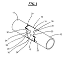
- a first tube 10 is joined in end-to-end relation with a second tube 12.
- the tubes 10 and 12 are connected at a tube joint 14 that includes a first locking piece 16 of the same material as the first tube 10 or of a material readily welded to the first tube 10 and a second locking piece 18 of the same material as the second tube 12 or of a material readily welded to the second tube 12.
- the locking pieces 16 and 18 are shaped to interlock with one another without requiring welding, brazing, soldering, gluing or other additional fastening measures.
- the view of Figure 1 shows only one side of the tube joint 14. Additional locking pieces are provided on the other side of the tube joint 14 that are not visible in the figure.
- the additional locking pieces may be of the same shape or different shapes as the locking pieces visible in Figure 1 .
- the illustrated tubes 10 and 12 are relatively short for purposes of illustration.
- the tubes may be of any desired length.
- the first locking piece 16 is welded at an interface 20 to the first tube 10 where the tube 10 and locking piece 16 contact one another.
- the second locking piece 18 is welded at an interface 22 to the second tube 12 where the tube 12 and locking piece 18 contact one another.
- a strong weld is formed at the interface 20.
- the second welded interface 22 is strong as a result of the second locking piece 18 being of the same or similar material to the tube 12 or of readily welded materials.
- the interlocked locking pieces 16 and 18 need not be welded to one another or otherwise glued, soldered or brazed to one another, yet the interlocked pieces 16 and 18 hold the tubes 10 and 12 together at the tube joint 14. The interlocking fit between the interlocked pieces provides the fastening of the tubes together.
- the interface between the interlocked pieces 16 and 18 provide surfaces that resist relative axial and rotational motion between the pieces. Relative rotational motion between the tubes 10 and 12 is prevented or restricted by axially extending interface surfaces 24 between the interlocking pieces 16 and 18 as well as by axially extending interface surfaces 26 between the locking pieces 16 or 18 and the tubes 10 or 12. Relative axial motion between the tubes 10 and 12 in a tension or pulling direction is prevented or restricted by transversely extending interface surfaces 28 between the locking pieces 16 and 18. The locking pieces 16 and 18 are prevented from pulling out of position in their respective tubes 10 and 12 by the weld seams 20 and 22.
- Relative axial motion between the tubes 10 and 12 in a compressing or pushing direction is prevented or restricted by transversely extending interface surfaces 30 between the first locking piece 16 and the second tube 12 and between the second locking piece 18 and the first tube 10.
- Shear forces are resisted by radial surfaces at the axially extending interface surfaces 24 and 26. Bending and other forces are a combination of these forces and are therefore also resisted by the tube joint 14 by the combination of interface surfaces.
- the tubes 10 and 12 and the locking pieces 16 and 18 are cut into the shapes as shown.
- the locking pieces each have a base portion 34 and two side extensions 36 and an end recess 38.
- Each locking piece 16 and 18 is of the same shape and size as the other locking pieces of the tube joint 14.
- Two locking pieces 16 are provided, disposed on opposite sides of the tube joint 14 from one another, and two locking pieces 18 are provided, also opposite one another.
- the locking pieces 16 are inverted end for end relative to the locking pieces 18 when joined to one another.
- the tubes 10 and 12 each include a base recess 40, an end face 42 and a projection 44 as cut surfaces extending transverse to the tube length.
- the transverse cut surfaces 40, 42 and 44 are connected by axial cut surfaces 46 and 48, which form a stair-step shaped cut end on the tubes 10 and 12.
- the cut shapes on the ends of the tubes 10 and 12 are rotated by 90 degrees relative to one another when being joined by the tube joint 14 so that the base recess 40 of one tube is opposite the projection 44 of the other tube.
- Other shapes of locking pieces and tube shapes are also possible and are within the scope of the present invention.
- the preferred locking pieces and tube shapes have a combination of interface surfaces to resist compression forces, tension forces and rotational forces.
- the cuts that form the illustrated tubes and locking pieces are performed by a laser cutting tool or other cutting tool.
- a precision cutting tool is used for the cuts.
- the cuts are made to form interface surfaces that extend radially through the thickness of the tube material relative to the axis of the tubes.
- thicker tubes have a larger interface surface at each cut and provide a more secure connection of the tubes to one another.
- the radially extending interface surfaces resist shear forces and other forces on the tube joint 14 and keep the tubes joined.
- the locking pieces 16, two of which are shown may be cut from the tube 10, cut from another tube of the same material, or cut from a tube of material that is readily welded to the tube 10.
- the locking pieces 18, two of which are shown may be cut from the tube 12, cut from a tube of the same material as the tube 12, or cut from a tube of a material that is readily welded to the tube 12.
- Figure 2b shows a step in the method of joining the tubes 10 and 12.
- the locking pieces 16 and 18 are positioned together in an interlocked configuration.
- the side extensions 36 of the locking pieces 16 are abutted against the base portions 34 of two adjoining locking pieces 18.
- the side extensions 36 of the locking pieces 18 are abutting against the base portions 34 of two adjoining locking pieces 16.
- the locking pieces 16 and 18 may be of incompatible materials that are not readily welded to one another and so no welding takes place at this step in the assembly process. It may be necessary to assemble the locking pieces 16 and 18 in a form or on a mandrel or otherwise to hold them in place. It is foreseeable that a wrap, coating or fastening may be applied to the locking pieces to hold them in position, either in conjunction with a form or mandrel or instead of the form or mandrel.
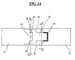
- welds are also made to join the tube 10 to the locking pieces 16 along the interface surfaces 40 and 46 where the base portion of the locking pieces 16 abut the tube 10. These welds are referred to as second welds, but as noted above the order in which the welds are performed is not limited by the designation.
- the first welds provide a strong bond between the parts since the locking pieces 18 and the tube 12 are of the same material or of materials that are compatible for welding.
- the second welds are also strong since the locking pieces 16 and the tube 10 are of the same material or of materials that are compatible for welding.
- the first welding of the locking pieces 18 and tube 12 are carried out using welding techniques that are appropriate for the materials being welded.
- the second welding of the locking pieces 16 to the tube 10 is carried out with welding techniques that are appropriate for the materials of which the tube 10 and locking pieces 16 are formed. Since the material of the tube 10 may be different than the material of the tube 12, the first and second welding techniques may differ from one another.
- first weld and second weld may differ simply because the materials being welded in the two welds do not readily bond to one another when welded to each other.
- one of the tubes is of a steel alloy and the other tube is of a nickel titanium alloy, also referred to as nitinol.
- Welding of the steel tube to the steel locking pieces is carried out using known steel welding techniques.
- Welding of the nitinol tube to the nitinol locking pieces is also carried out using known welding techniques, such as welding in an inert atmosphere using laser, TiG or resistance welding techniques. Other materials may be joined with the present method and apparatus as well.
- the cross section through the tube joint 14 reveals the radially directed interface surfaces between the parts.
- the radial interface surfaces are along the axially directed cuts.
- the projection 44 of the tube 10 has interface surfaces 48 that abut the lateral extensions 36 of the locking piece 18.
- the lateral extensions 36 have interface surfaces 52 that abut the base portions 34 of the locking pieces 16.
- the other side is mirror symmetrical with the same arrangement of parts and interface surfaces.
- the locking piece 18 is not welded to the tube 10 but is constrained from moving in the x and y directions by the angles of the radial mating surfaces between it and the parts 44 and 16.
- the locking piece 18 cannot move radially outwards or inwards due to the angles of the radial mating surfaces between the locking piece 16 and the part 44.
- the locking piece 18 is prevented from moving axially by the lateral shoulders and welds.
- a key to the method is the radial mating surfaces and how these surfaces are distributed around the circumference of the joint. They act like act like keystone in an arch.
- the sectional views illustrate this principal. Looking at Figure 3b , the two pieces of locking part 18 on the left hand side are actually one piece and cannot move independently, therefore they cannot move in any direction but axially, and are constrained from doing so by the lateral shoulders once welding of the parts has occurred.
- the cross section through the tube joint 14 at the line B-B of Figure 3a reveals the same arrangement of interface surfaces but the interface surfaces are between different parts than shown in Figure 3b .
- a base portion 34 of the locking piece 18 has interface surfaces 52 that abut the lateral extensions 36 of the locking pieces 16 on both sides.
- the lateral pieces 36 of the locking pieces abut the projections 44 of the tube 12 at the interface surfaces 48.
- the other side is mirror symmetrical with the same arrangement of parts and interface surfaces.
- the locking piece 16 is not welded to tube 12 but is constrained from moving in the x and y directions by the angles of the radial mating surfaces between it and the parts 44 and 18.
- the locking piece 16 cannot move radially outwards or inwards due to the angles of the radial mating surfaces between the locking piece 18 and the part 44.
- the locking piece 16 is prevented from moving axially by the lateral shoulders and welds.
- the radial mating surfaces distributed about the circumference of the tubular joint in conjunction with the lateral shoulders and the welded base portions constrain motion of the tubes at the tube joint.
- the present method to join two tubes of the same diameter and same wall thickness end to end without deforming the tubes, without changing the wall thickness, without increasing the outside diameter or decreasing the inside diameter, and without requiring welding of the two tube materials to one another and without requiring brazing, soldering, gluing or the like. It is within the scope of the present invention that the tubes to be joined are of different wall thicknesses and/or different diameters and may be of the same or different materials.
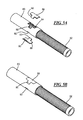
- FIG. 4a An alternative embodiment of the present method is shown in Figure 4a .
- a tube is to be joined to a tube or cylinder 62 of sufficiently smaller diameter to fit into the end of the tube 60.
- the tube 60 and the tube or cylinder 62 may be of the same material, but the advantages of the invention are realized when the two components are of different materials that are not easily or readily welded.
- the tube 60 is cut to define two cutouts 64. Other numbers of cutouts may be provided in other embodiments, such as one cutout, three cutouts or four cutouts, for example.
- Two locking pieces 66 are formed of a material that is readily welded to the tube or cylinder 62.
- the two locking pieces 66 are shaped each with an extension portion 68 that fits into the cutouts 64.
- the extension portion 68 is connected to a base portion 70.
- the locking pieces 66 are formed from a tube of substantially the same diameter as the tube 60 and of an interior diameter that fits over the outer diameter of the tube or cylinder 62.
- the extension portion 68 of the locking pieces 66 include lateral extensions 72 that extend laterally from the extension portion 68. Corresponding lateral extensions 74 are formed in the cutouts 64. The lateral extensions 72 within the lateral extensions 74 of the cutouts resists tension or pulling on the tube joint to prevent the locking pieces 66 from being pulled from the tube 60.
- the locking pieces 66 are configured so that the radial surfaces of the axially directed cuts are arranged circumferentially and distributed in such a way as to constrain movement of the tube 60 relative to the tube 62 once the locking pieces 66 have been welded to the tube 62.
- the tube or cylinder 62 of the illustrated embodiment is a cable formed of cable wires 76 around a hollow core 78, or the cable may be a solid cable of cable wires, or may have other forms and may include an end cap or weld 80 to prevent fraying.
- the cable 62 may be of steel and the tube 60 of nitinol so that welding the two components together is not readily or easily done.
- the locking pieces 66 are of steel so that they can be easily welded to the cable 62. It is also within the scope of the present invention that the tube 60 is of steel or other material and that the cylinder or cable 62 is of nitinol or other material.
- the cylinder or cable 62 may be solid or may be hollow. It is within the scope of the invention that a solid cylinder is affixed to the tube 60 in the manner shown.
- the cable 62 has been inserted into the end of the tube 60.
- the locking pieces 66 are positioned with the extension portions 68 in the cutouts 64 of the tube 60 and the base portions 70 encircling the cable 62 at the end of the tube 60.
- the locking pieces 66 are welded to the cable 62, which is readily accomplished as the locking pieces 66 are of the same material or at least of a sufficiently similar material to the cable so that they are readily welded.
- FIG. 5a an alternate embodiment of method for attaching a tube 80 to a cylinder or tube 82 is shown.
- the cylinder or tube 82 in the illustration is a hollow cable.
- the tube 80 has cutouts 84 at one or more locations on the tube 80.
- the cylinder or tube 82 fits within the tube 80 so that it is accessible through the openings that result from the cutouts 84.
- the cutouts 84 in this embodiment are spaced from the end 86 of the tube 80 and the cutout 84 is enclosed by the tube wall rather than being open to the end as in the above-described embodiments.
- Locking pieces 88 are prepared from a tube of material that is weld-compatible with the cable or cylinder 82 and shaped to fit into the cutouts 84.
- the cutouts 84 and the locking pieces 88 are provided with radial interface surfaces at the edges.
- the locking pieces 88 include lateral extensions 90 that fit within lateral extensions 92 of the cutouts 84.
- the lateral extensions provide additional radial mating surfaces at different circumferential locations to allow a wider distribution of mating surfaces around the circumference.
- the radial mating surfaces play a key role in joining the pieces to one another.
- the locking pieces 88 have been placed into the cutouts 84 in the tube 80 and have been welded to the cable or cylinder 82.
- the cable 82 is fastened in place in the tube 80 without being welded to the tube.
- a low profile, strong and reliable welded joint is provided between potentially incompatible materials without requiring the special welding techniques that would ordinarily be required of welding the incompatible materials.
- At least one locking piece formed of a material that is the same or substantially similar to a first of the tubes is provided in a cut-out at the end of the second tube and welded or otherwise secured or affixed to the first tube. The interlock of the locking piece in the second tube secures the first and second tubes together.
- Two locking pieces of material of the first tube and two locking pieces of material of the second tube are positioned in an interlocking arrangement without welding or otherwise fastening the locking pieces to one another.
- the locking pieces of the material of the first tube are welded to the first tube.
- the locking pieces of the material of the second tube are welded to the second tube.
- the interlocked locking pieces secure the first and second tubes to one another without requiring welding of the dissimilar materials of the first and second tubes.
- the present method and tube joints encompasses many possible arrangements of locking pieces.
- two locking pieces per material are provided, although three or four may be used.
- the two tubes are of the same or substantially the same inside and outside diameters but are of different materials, as a result of which it may not be possible to weld the two different materials to one another in a simple manner.
- two locking pieces are fit into cutouts in a tube and are welded to a second member of a different material and a different diameter so that the second member fits into the tube.
- the cutouts may extend to the end of the tube or be enclosed within the tube walls.
- Welding of the similar or same material lock and tube components to one another is one possible method for attaching these components.
- Different types of welding techniques are being considered and are within the scope of the present invention.
- Other fastening techniques including brazing, gluing, ultrasonic welding, stamping, soldering and all other fastening techniques are encompassed here.
- the technique of cutting or forming the tube ends and locking elements encompass cutting by laser cutting, mechanical cutting, stamping, molding and all other forming and cutting techniques.
- the lock elements can be cut from the tube that they are to be fastened to, or may be formed or cut from another tube or other supply of material.
- a quantity of tubes may be shaped and a quantity of lock elements may be formed, and any of the lock elements joined to any of the tubes, such as might occur in a manufacturing line where parts are taken from a supply for assembly.
- the tubes may be of metal, such as steel and other metal alloys, or may be of other materials including ceramic, plastic, carbon fibers or any other materials.
- the solution allows a joint to be made with no increase in OD and no decrease in ID, allows dissimilar materials to be mechanically joined without requiring adhesive, weld, solder, braze or other between the dissimilar materials.
- This method does not require an increase in OD or decrease in ID. Axial forces are carried by the interlocking shoulders of the interface surfaces. The geometry of the parts and the distribution of the radial cuts around the circumference lock the tubes together.
- the locking pieces may be assembled together and held by heat-shrink or other method. In some instances it will be necessary to provide the additional support of a heat-shrink tube over the joined tubes but in other instances this may be unnecessary.
- the tubes are assembled onto the lock sub assembly.
- the tubes may be lined, coated on interior and/or exterior surfaces, mounted within or around other structures, and/or may carry liquids, gases, semisolids or other materials.
- the interfaces between the interlocking elements may be sealed or left unsealed.
- Niti nitinol
- stainless steel for instance, gluing, lap or press fit joints.
- a method of joining tubes to one another to another element such as a shaft or sleeve.
- the present method allows a joint to be made between nitinol and stainless steel without having to make the difficult and potentially brittle niti to stainless steel weld.
- Locking pieces cut with appropriate geometry from both types of material are interlocked, constraining movement in most directions.
Landscapes
- Engineering & Computer Science (AREA)
- General Engineering & Computer Science (AREA)
- Mechanical Engineering (AREA)
- Butt Welding And Welding Of Specific Article (AREA)
Description
- The present invention relates generally to a method of joining a first tube to a second tube, and tube joints according to the preamble of
claims 1, 14 and 18 (see, for example,US 2006/00 6649 A ). - Tubes are used in a variety of fields and for a variety of purposes. For instance, tubular members are used in the medical field in medical devices. One application of tubular members is as a component of a system for delivery of medical devices to locations within the human body such as within any lumen of the body. For example, the tubes may be used to deliver medical devices within the vasculature, the biliary system, the oesophagus or the gastro-intestinal tract. Of course, tubes are used in many other fields and for many other purposes as well.
- It is sometimes necessary to join two tubes to one another and in some applications it is important that the joining of the tubes not result in an increase in the outside diameter of the tubes at the joint and that the joining not result in a decrease in the inside diameter of the tubes at the joint. Where tubes to be joined are of a similar material, it may be possible to join the tubes by welding using a so-called butt joint. Where dissimilar materials are to be joined, the materials may not be readily weldable to one another. Some tube materials may be joined by gluing, brazing or soldering of the butt joint; however, it may be problematic to join dissimilar materials even with these techniques and the fact that only a small bonding surface area is available at the joint can result in a joint that is not sufficiently strong.
- A lap joint increases the joint strength by increasing the bonding surface area but increases the wall thickness at the joint. A half lap joint where the material thickness of both parts is reduced in the joint area, resulting in a larger bonding area with no increase in the wall thickness at the joint, may not be practical for thin wall tubes. Lap joints between dissimilar tubular materials can be weak or require substantial overlap areas to achieve adequate bond strengths.
- Other techniques for joining tubes to one another are possible, such as press fit, shrink fit, crimping, or the like, but these result in either an increased outer diameter, a decreased inner diameter, or both. Other joining techniques may also result in deformation of the tube, weakening of the tube, or other issues.
- Joining dissimilar materials in general can also be troublesome, such as when it is necessary to join a tube to another member such as a tube or a cable, particularly where the tube and other member are of different materials. For instance, welding of nitinol to stainless steel results in brittle intermetallic compounds, such as TiFe and TiFe2, which makes the resulting weld brittle. Using an intermediate material to avoid the formation of such brittle compounds is not practical in all applications.
- Thus, joining tubes of dissimilar materials can be problematic if the materials are not readily weldable to each other nor reliably joined by other means such as brazing, soldering, gluing, press fit or shrink fit. This is particularly true where it is desired to create a joint connecting tubes or other members without an increase to the outside dimensions of the tube and without decreasing the inside dimensions of the tube.
-
US 2006/006649 A1 to Galdonik et al. discloses a medical device such as a catheter or hypotube that has a mechanical locking interface. The mechanical lock can be provided on the corewire by shaping the wire to couple so the segments are fixed along the major axis and to disengage by movement perpendicular to the major axis. The corewire is inserted into the tube to hold the mechanical lock together by preventing the perpendicular movement of the two segments of the corewire. -
US 5,853,375 A to Orr discloses an angioplasty guide wire that is connected to an extension wire by a peg and hole connection. A horizontal surface is formed with a hole in it on a first segment of wire and a horizontal surface with a peg extending from it is formed on a second segment of wire. The peg is inserted into the hole to form a connection of the two wire segments. The wire segments are made from magnetic material so that magnetic attraction holds the segments together. An embodiment with a slot receives the peg with a latch at the end so that a 90 degree rotation of the segments connects and disconnects the segments. -
DE 10 2006 035191 A1 to Osypka discloses a biopsy cannula that has a steel part (2) and a nitinol part (3) with a connecting position (4) formed as supports or as projection in a pipe or sleeve shape. A connecting sleeve (5) engages and overlaps the steel part and the nitinol part. The connecting sleeve is connected with the steel part in a form fit manner through screwing, welding and riveting and with the nitinol part in a mechanical and form fit manner. The steel part and the nitinol part are connected with each another in a form fit manner. -
US 2003/0028127 A1 to Balzum et al discloses devices and methods for coupling guidewire system components. - According to the invention, a method for joining a first tube to a second tube in an end-to-end connection is set out in claim 1. Tube joints comprising a first tube joined to a second tube are also set out in
claims - The present invention provides a method and apparatus that allows tubes to be joined to one another in end-to-end connection without increasing the outer diameter (OD) of the tubes and without decreasing the inner diameter (ID) of the tubes. In other words, the materials are joined without increasing the wall thickness at the joint. The present method and apparatus is particularly well suited to joining relatively thick wall tubes to one another as well as for joining tubes of different materials that have different material characteristics to one another, such as where those materials are not readily welded to one another. An example of the different materials that may be joined using the present method is joining a stainless steel tube to a nitinol tube.
- By cutting the tubular materials with radial cuts using a tube cutting laser system or other method, the tubular pieces can be arranged in various interlocking patterns so that the cut faces of the pieces restrain movement between different pieces in different directions. By cutting interlocking pieces of different tubular materials, by arranging the pieces in an interlocking arrangement and by welding or attaching only similar materials to one another, the different tubes can be joined to one another without the requirement to weld tubes of different materials to one another.
- The method may also be used to provide a lap joint to join a tube or tool or other device of generally tubular shape to a member such as a cylindrical member, for example, a cable or wire, that may be of a different material than the tube. One or more pieces is cut from the tube and replaced by an interlocking piece that is securely fastenable to the cylindrical member. The cylindrical member may be hollow or solid.
- The interlocked pieces are formed by cutting the tubes with radial cuts to make locking pieces which can be assembled to join the tubes together. The assembled pieces are fixed in place by welding or other attachment methods of the locking pieces to the body of the tubes of the same material. The present method avoids the need to weld or otherwise attach dissimilar materials to one another or to add structures to or otherwise modify the joined tubes in a way that would change the inside diameter or the outside diameter and avoids as well crimping or otherwise deforming the tubes to effect the joining.
-
-
Figure 1 is a side perspective view of two tubes joined end-to-end using interlocking pieces according to the principles of the present invention; -
Figure 2a is an exploded view showing the parts that are joined to form the joined tubes ofFigure 1 ; -
Figure 2b is a partially assembled view showing an intermediate joining step in the joining of the tubes ofFigure 1 ; -
Figure 3a is a side view of two tubes joined end-to-end indicating a location of a weld; -
Figure 3b is a cross-sectional view of the joined tubes along line A-A ofFigure 3a ; -
Figure 3c is a cross-sectional view of the joined tubes along line B-B ofFigure 3a ; -
Figure 4a is an exploded view showing parts for joining a tube to a cylinder according to an embodiment of the present invention; -
Figure 4b is a perspective view of the joined tube and cylinder after assembly of the parts show in ofFigure 4a ; -
Figure 5a is an exploded view showing the parts for joining a tube and a cylinder according to another embodiment of the present invention; and -
Figure 5b is a perspective view of the joined tube and cylinder after assembly of the parts show in ofFigure 5a . - Referring to
Figure 1 of the drawings, afirst tube 10 is joined in end-to-end relation with asecond tube 12. Thetubes tube joint 14 that includes afirst locking piece 16 of the same material as thefirst tube 10 or of a material readily welded to thefirst tube 10 and asecond locking piece 18 of the same material as thesecond tube 12 or of a material readily welded to thesecond tube 12. Thelocking pieces Figure 1 shows only one side of the tube joint 14. Additional locking pieces are provided on the other side of the tube joint 14 that are not visible in the figure. The additional locking pieces may be of the same shape or different shapes as the locking pieces visible inFigure 1 . The illustratedtubes - The
first locking piece 16 is welded at aninterface 20 to thefirst tube 10 where thetube 10 and lockingpiece 16 contact one another. Thesecond locking piece 18 is welded at aninterface 22 to thesecond tube 12 where thetube 12 and lockingpiece 18 contact one another. By welding thefirst locking piece 16 to thetube 10 of the same material, of a similar material, or of materials that are readily welded, a strong weld is formed at theinterface 20. Similarly, the second weldedinterface 22 is strong as a result of thesecond locking piece 18 being of the same or similar material to thetube 12 or of readily welded materials. The interlockedlocking pieces pieces tubes - The interface between the interlocked
pieces tubes interface surfaces 24 between the interlockingpieces interface surfaces 26 between the lockingpieces tubes tubes interface surfaces 28 between the lockingpieces pieces respective tubes tubes interface surfaces 30 between thefirst locking piece 16 and thesecond tube 12 and between thesecond locking piece 18 and thefirst tube 10. Shear forces are resisted by radial surfaces at the axially extendinginterface surfaces - It is foreseeable and within the scope of the present invention to provide a glue, sealant, solder, coating or other material to the tube joint, for example to seal the interface surfaces if desired, although this is not necessary for the strength of the tube joint 14. The interface surfaces may be fit together tightly so as to permit no relative movement therebetween or may fit a bit more loosely so that some, albeit slight, relative movement is possible between the
tubes - In
Figure 2a , thetubes pieces base portion 34 and twoside extensions 36 and anend recess 38. Each lockingpiece pieces 16 are provided, disposed on opposite sides of the tube joint 14 from one another, and two lockingpieces 18 are provided, also opposite one another. The lockingpieces 16 are inverted end for end relative to the lockingpieces 18 when joined to one another. - The
tubes base recess 40, anend face 42 and aprojection 44 as cut surfaces extending transverse to the tube length. The transverse cut surfaces 40, 42 and 44 are connected by axial cut surfaces 46 and 48, which form a stair-step shaped cut end on thetubes tubes base recess 40 of one tube is opposite theprojection 44 of the other tube. Other shapes of locking pieces and tube shapes are also possible and are within the scope of the present invention. The preferred locking pieces and tube shapes have a combination of interface surfaces to resist compression forces, tension forces and rotational forces. - The cuts that form the illustrated tubes and locking pieces are performed by a laser cutting tool or other cutting tool. Preferably, a precision cutting tool is used for the cuts. The cuts are made to form interface surfaces that extend radially through the thickness of the tube material relative to the axis of the tubes. Although it is possible to use the present method and apparatus with thin walled tubes, thicker tubes have a larger interface surface at each cut and provide a more secure connection of the tubes to one another. The radially extending interface surfaces resist shear forces and other forces on the tube joint 14 and keep the tubes joined.
- The locking
pieces 16, two of which are shown, may be cut from thetube 10, cut from another tube of the same material, or cut from a tube of material that is readily welded to thetube 10. Similarly, the lockingpieces 18, two of which are shown, may be cut from thetube 12, cut from a tube of the same material as thetube 12, or cut from a tube of a material that is readily welded to thetube 12. -
Figure 2b shows a step in the method of joining thetubes pieces side extensions 36 of the lockingpieces 16 are abutted against thebase portions 34 of two adjoininglocking pieces 18. Similarly, theside extensions 36 of the lockingpieces 18 are abutting against thebase portions 34 of two adjoininglocking pieces 16. The lockingpieces pieces - Turning to
Figure 3a , theinterconnected locking pieces tubes pieces 18 and thetube 12, as indicated at 50. Theweld 50 runs along the interface surfaces 40 and 46. As a result of theweld 50, the lockingpiece 18 and thetube 12 are bonded to one another. A similar weld is made to join theother locking piece 18 to thetube 12 at the interface surfaces 40 and 46 on the other side of thetube 12. These welds will be referred to in the following as first welds, although the designation should not be interpreted as indicating a particular order for performing the welding steps. Welds are also made to join thetube 10 to the lockingpieces 16 along the interface surfaces 40 and 46 where the base portion of the lockingpieces 16 abut thetube 10. These welds are referred to as second welds, but as noted above the order in which the welds are performed is not limited by the designation. - The first welds provide a strong bond between the parts since the locking
pieces 18 and thetube 12 are of the same material or of materials that are compatible for welding. The second welds are also strong since the lockingpieces 16 and thetube 10 are of the same material or of materials that are compatible for welding. The first welding of the lockingpieces 18 andtube 12 are carried out using welding techniques that are appropriate for the materials being welded. The second welding of the lockingpieces 16 to thetube 10 is carried out with welding techniques that are appropriate for the materials of which thetube 10 and lockingpieces 16 are formed. Since the material of thetube 10 may be different than the material of thetube 12, the first and second welding techniques may differ from one another. For example, it may be necessary to weld at different temperatures, at a different rate, with different equipment, with a different filler material, or other differences. The first weld and second weld may differ simply because the materials being welded in the two welds do not readily bond to one another when welded to each other. - In one example, one of the tubes is of a steel alloy and the other tube is of a nickel titanium alloy, also referred to as nitinol. Welding of the steel tube to the steel locking pieces is carried out using known steel welding techniques. Welding of the nitinol tube to the nitinol locking pieces is also carried out using known welding techniques, such as welding in an inert atmosphere using laser, TiG or resistance welding techniques. Other materials may be joined with the present method and apparatus as well.
- In
Figure 3b , the cross section through the tube joint 14 reveals the radially directed interface surfaces between the parts. The radial interface surfaces are along the axially directed cuts. For instance, theprojection 44 of thetube 10 has interface surfaces 48 that abut thelateral extensions 36 of the lockingpiece 18. Thelateral extensions 36 haveinterface surfaces 52 that abut thebase portions 34 of the lockingpieces 16. The other side is mirror symmetrical with the same arrangement of parts and interface surfaces. The lockingpiece 18 is not welded to thetube 10 but is constrained from moving in the x and y directions by the angles of the radial mating surfaces between it and theparts piece 18 cannot move radially outwards or inwards due to the angles of the radial mating surfaces between the lockingpiece 16 and thepart 44. The lockingpiece 18 is prevented from moving axially by the lateral shoulders and welds. A key to the method is the radial mating surfaces and how these surfaces are distributed around the circumference of the joint. They act like act like keystone in an arch. The sectional views illustrate this principal. Looking atFigure 3b , the two pieces of lockingpart 18 on the left hand side are actually one piece and cannot move independently, therefore they cannot move in any direction but axially, and are constrained from doing so by the lateral shoulders once welding of the parts has occurred. - In
Figure 3c , the cross section through the tube joint 14 at the line B-B ofFigure 3a reveals the same arrangement of interface surfaces but the interface surfaces are between different parts than shown inFigure 3b . In particular, abase portion 34 of the lockingpiece 18 has interface surfaces 52 that abut thelateral extensions 36 of the lockingpieces 16 on both sides. Thelateral pieces 36 of the locking pieces abut theprojections 44 of thetube 12 at the interface surfaces 48. The other side is mirror symmetrical with the same arrangement of parts and interface surfaces. The lockingpiece 16 is not welded totube 12 but is constrained from moving in the x and y directions by the angles of the radial mating surfaces between it and theparts piece 16 cannot move radially outwards or inwards due to the angles of the radial mating surfaces between the lockingpiece 18 and thepart 44. The lockingpiece 16 is prevented from moving axially by the lateral shoulders and welds. As noted above, the radial mating surfaces distributed about the circumference of the tubular joint in conjunction with the lateral shoulders and the welded base portions constrain motion of the tubes at the tube joint. - Thus, it is possible with the present method to join two tubes of the same diameter and same wall thickness end to end without deforming the tubes, without changing the wall thickness, without increasing the outside diameter or decreasing the inside diameter, and without requiring welding of the two tube materials to one another and without requiring brazing, soldering, gluing or the like. It is within the scope of the present invention that the tubes to be joined are of different wall thicknesses and/or different diameters and may be of the same or different materials.
- An alternative embodiment of the present method is shown in
Figure 4a . Instead of joining two tubes of the same diameter as described in the foregoing, a tube, is to be joined to a tube orcylinder 62 of sufficiently smaller diameter to fit into the end of thetube 60. Thetube 60 and the tube orcylinder 62 may be of the same material, but the advantages of the invention are realized when the two components are of different materials that are not easily or readily welded. In the illustrated example, thetube 60 is cut to define twocutouts 64. Other numbers of cutouts may be provided in other embodiments, such as one cutout, three cutouts or four cutouts, for example. Two lockingpieces 66 are formed of a material that is readily welded to the tube orcylinder 62. The two lockingpieces 66 are shaped each with anextension portion 68 that fits into thecutouts 64. Theextension portion 68 is connected to abase portion 70. The lockingpieces 66 are formed from a tube of substantially the same diameter as thetube 60 and of an interior diameter that fits over the outer diameter of the tube orcylinder 62. - The
extension portion 68 of the lockingpieces 66 includelateral extensions 72 that extend laterally from theextension portion 68. Correspondinglateral extensions 74 are formed in thecutouts 64. Thelateral extensions 72 within thelateral extensions 74 of the cutouts resists tension or pulling on the tube joint to prevent the lockingpieces 66 from being pulled from thetube 60. The lockingpieces 66 are configured so that the radial surfaces of the axially directed cuts are arranged circumferentially and distributed in such a way as to constrain movement of thetube 60 relative to thetube 62 once the lockingpieces 66 have been welded to thetube 62. - The tube or
cylinder 62 of the illustrated embodiment is a cable formed ofcable wires 76 around ahollow core 78, or the cable may be a solid cable of cable wires, or may have other forms and may include an end cap orweld 80 to prevent fraying. Thecable 62 may be of steel and thetube 60 of nitinol so that welding the two components together is not readily or easily done. The lockingpieces 66 are of steel so that they can be easily welded to thecable 62. It is also within the scope of the present invention that thetube 60 is of steel or other material and that the cylinder orcable 62 is of nitinol or other material. The cylinder orcable 62 may be solid or may be hollow. It is within the scope of the invention that a solid cylinder is affixed to thetube 60 in the manner shown. - In
Figure 4b , thecable 62 has been inserted into the end of thetube 60. The lockingpieces 66 are positioned with theextension portions 68 in thecutouts 64 of thetube 60 and thebase portions 70 encircling thecable 62 at the end of thetube 60. The lockingpieces 66 are welded to thecable 62, which is readily accomplished as the lockingpieces 66 are of the same material or at least of a sufficiently similar material to the cable so that they are readily welded. By positioning the lockingpieces 66 in the cutouts of thetube 60 and welding the locking pieces to thecable 62, thecable 62 is weld fastened to thetube 60 without the need to weld thetube 60 to thecable 62. - Referring to
Figure 5a , an alternate embodiment of method for attaching atube 80 to a cylinder ortube 82 is shown. The cylinder ortube 82 in the illustration is a hollow cable. Thetube 80 hascutouts 84 at one or more locations on thetube 80. The cylinder ortube 82 fits within thetube 80 so that it is accessible through the openings that result from thecutouts 84. Thecutouts 84 in this embodiment are spaced from the end 86 of thetube 80 and thecutout 84 is enclosed by the tube wall rather than being open to the end as in the above-described embodiments. - Locking
pieces 88 are prepared from a tube of material that is weld-compatible with the cable orcylinder 82 and shaped to fit into thecutouts 84. In the preferred embodiment, thecutouts 84 and the lockingpieces 88 are provided with radial interface surfaces at the edges. The lockingpieces 88 includelateral extensions 90 that fit withinlateral extensions 92 of thecutouts 84. The lateral extensions provide additional radial mating surfaces at different circumferential locations to allow a wider distribution of mating surfaces around the circumference. The radial mating surfaces play a key role in joining the pieces to one another. - Referring to
Figure 5b , the lockingpieces 88 have been placed into thecutouts 84 in thetube 80 and have been welded to the cable orcylinder 82. By virtue of the weld connection between the lockingpieces 88 and thecable 82, thecable 82 is fastened in place in thetube 80 without being welded to the tube. - In the illustrated embodiments, a low profile, strong and reliable welded joint is provided between potentially incompatible materials without requiring the special welding techniques that would ordinarily be required of welding the incompatible materials.
- Thus, there is shown and described a method for joining two tubes of dissimilar material to one another in alignment with one another without increasing the outside diameter of the tubes or decreasing the inside diameter of the tubes. At least one locking piece formed of a material that is the same or substantially similar to a first of the tubes is provided in a cut-out at the end of the second tube and welded or otherwise secured or affixed to the first tube. The interlock of the locking piece in the second tube secures the first and second tubes together.
- Two locking pieces of material of the first tube and two locking pieces of material of the second tube are positioned in an interlocking arrangement without welding or otherwise fastening the locking pieces to one another. The locking pieces of the material of the first tube are welded to the first tube. The locking pieces of the material of the second tube are welded to the second tube. The interlocked locking pieces secure the first and second tubes to one another without requiring welding of the dissimilar materials of the first and second tubes.
- The present method and tube joints encompasses many possible arrangements of locking pieces. In the illustrated examples two locking pieces per material are provided, although three or four may be used. The two tubes are of the same or substantially the same inside and outside diameters but are of different materials, as a result of which it may not be possible to weld the two different materials to one another in a simple manner. Also in the illustrated examples two locking pieces are fit into cutouts in a tube and are welded to a second member of a different material and a different diameter so that the second member fits into the tube. The cutouts may extend to the end of the tube or be enclosed within the tube walls.
- Welding of the similar or same material lock and tube components to one another is one possible method for attaching these components. Different types of welding techniques are being considered and are within the scope of the present invention. Other fastening techniques including brazing, gluing, ultrasonic welding, stamping, soldering and all other fastening techniques are encompassed here. The technique of cutting or forming the tube ends and locking elements encompass cutting by laser cutting, mechanical cutting, stamping, molding and all other forming and cutting techniques. The lock elements can be cut from the tube that they are to be fastened to, or may be formed or cut from another tube or other supply of material. A quantity of tubes may be shaped and a quantity of lock elements may be formed, and any of the lock elements joined to any of the tubes, such as might occur in a manufacturing line where parts are taken from a supply for assembly.
- The tubes may be of metal, such as steel and other metal alloys, or may be of other materials including ceramic, plastic, carbon fibers or any other materials.
- The solution allows a joint to be made with no increase in OD and no decrease in ID, allows dissimilar materials to be mechanically joined without requiring adhesive, weld, solder, braze or other between the dissimilar materials.
- This method does not require an increase in OD or decrease in ID. Axial forces are carried by the interlocking shoulders of the interface surfaces. The geometry of the parts and the distribution of the radial cuts around the circumference lock the tubes together.
- By arranging the mating surfaces at various angles, distributed over the circumference of the tubes, a joint is formed which will restrain relative movement between the tubes in all directions. The lock pieces fit together radially and axially and once welded into position to their respective tubes the joint is complete.
- The locking pieces may be assembled together and held by heat-shrink or other method. In some instances it will be necessary to provide the additional support of a heat-shrink tube over the joined tubes but in other instances this may be unnecessary. The tubes are assembled onto the lock sub assembly.
- The tubes may be lined, coated on interior and/or exterior surfaces, mounted within or around other structures, and/or may carry liquids, gases, semisolids or other materials. The interfaces between the interlocking elements may be sealed or left unsealed.
- Other solutions may involve butt welding dissimilar materials, Niti (nitinol) to stainless steel for instance, gluing, lap or press fit joints.
- Thus, there is shown and described a method of joining tubes to one another to another element such as a shaft or sleeve. The present method allows a joint to be made between nitinol and stainless steel without having to make the difficult and potentially brittle niti to stainless steel weld. Locking pieces cut with appropriate geometry from both types of material are interlocked, constraining movement in most directions. Once this assembly is welded on to both tubes, the locking pieces of the first material welded to the tube of the first material and locking pieces of second material to tube of the second material, the parts are constrained from relative movement in all directions, thereby completing the joint.
- Although other modifications and changes may be suggested by those skilled in the art, it is the intention of the inventors to embody within the patent warranted hereon all changes and modifications come within the scope of the appended claims.
Claims (20)
- A method of joining a first tube (10) to a second tube (12) in end-to-end connection, comprising the steps of:cutting a shaped cutout (40) at an end of a first tube (10) with radial cut faces on axially aligned portions (46, 48) of the cuts;cutting a shaped cutout (40) at an end of a second tube (12) with radial cut faces on axially aligned portions (46, 48) of the cuts; and characterised by the following steps:cutting first and second locking pieces (16, 18) from at least one tube with radial cut faces on axially aligned portions of the cuts;arranging said first and second locking pieces (16, 18) in interlocking relation with the radial cut surfaces (48, 52) distributed circumferentially around the joint so as to constrain relative movement between the parts;welding said first locking pieces (16) to said first tube (10) at said shaped cutout; andwelding said second locking pieces (18) to said second tube (12) in said shaped cutout, so as to form a tube joint joining said first and second tubes (10, 12) to one another.
- A method as claimed in claim 1, wherein said first tube (10) and said second tube (12) are of substantially the same diameter and are joined end to end.
- A method as claimed in claim 2, wherein said first tube (10) and said second tube (12) have substantially the same inside diameter and substantially the same outside diameter.
- A method as claimed in claim 1, or claim 2, or claim 3, wherein said first tube (10) is of a different material than said second tube (12),
said first locking pieces (16) being of a different material than said second locking pieces (18); and
said welding of said first locking pieces (16) to said first tube (10) being performed by a different welding technique than said welding of said second locking pieces (18) to said second tube (12). - A method as claimed in claim 1, or in any of claims 2 to 4, wherein said first and second locking pieces (16, 18) are cut from different tubes or are formed of different materials.
- A method as claimed in claim 1, or in any of claims 2 to 5, wherein said first tube (10) and said first locking pieces (16) are of nitinol and wherein said second tube (12) and said second locking pieces (18) are of steel.
- A method as claimed in claim 1, or in any of claims 2 to 6, wherein said step of cutting said first and second locking pieces (16, 18) includes cutting said locking pieces to include a base portion (34) and lateral extensions (36) with radial cut faces on the axially aligned cuts,
wherein said step of arranging said locking pieces (16, 18) in interlocking relation includes arranging said lateral extensions (36) of said first locking pieces (16) to engage said lateral extensions (36) of said second locking pieces (18); and
wherein said steps of welding include welding said base portions (34) of said first locking pieces (16) to said first tube (10) and welding said base portions (34) of said second locking pieces (18) to said second tube (12) while said lateral extensions of said first and second locking pieces (16, 18) are engaged with one another. - A method as claimed in claim 1, or in any of claims 2 to 7, wherein said step of cutting said first and second locking pieces (16, 18) includes cutting said locking pieces from tubes of a substantially a same diameter as said first and second tubes (10, 12).
- A method as claimed in claim 1, or in any of claims 2 to 8, wherein said step of arranging said first and second locking pieces (16, 18) includes arranging two of said first locking pieces (16) and two of said second locking pieces (18) in said interlocking relation.
- A method as claimed in claim 1, or in any of claims 2 to 9, wherein said first and second locking pieces (16, 18) are of substantially the same size and shape as one another but of mutually different materials.
- A method as claimed in claim 1, or in any of claims 2 to 10, wherein said welding step of welding said first locking pieces (16) welds only along an interface between said first locking pieces (16) and said first tube (10), and wherein said welding step of welding said second locking pieces (18) welds only along an interface between said second locking pieces (18) and said second tube (12), said tube joint being otherwise free of welds.
- A method as claimed in claim 1, or in any of claims 2 to 11, wherein said cutting steps are performed using a laser cutting tool.
- A method as claimed in claim 1, or in any of claims 2 to 12, wherein said welding of said first tube is performed in an inert atmosphere.
- A tube joint comprising:a first tube (10) of a first material joined to a second tube (12) of a second material; and characterised by :first locking pieces (16) cut free from a tube of a first material, said first locking pieces (16) including lateral extensions (36), said first locking pieces include radial cut faces on axially aligned portions of cut surfaces;second locking pieces (18) cut free from a tube of a second material, said second locking pieces (18) including lateral extensions (36), said second locking pieces include radial cut faces on axially aligned portions of cut surfaces;said first locking pieces (16) and said second locking pieces (18) arranged in interlocking relation with said lateral extensions (36) of said respective first locking pieces (16) engaging said lateral extensions (36) of second locking pieces (18) and with the radial cut faces (48, 52) distributed circumferentially around the joint so as to constrain relative movements between the parts; andsaid first locking pieces (16) being welded to the first tube (10) and said second locking pieces (18) being welded to the second tube (12).
- A tube joint as claimed in claim 14, wherein said first locking pieces (16) are cut from a tube of a same material as said first tube (10), said second locking pieces (18) being cut from a tube of the same material as said second tube (12).
- A tube joint as claimed in claim 14, or in claim 15, wherein said first locking pieces (16) are two first locking pieces and wherein said second locking pieces (18) are two second locking pieces.
- A tube joint as claimed in claim 14, or in claim 15, or of claim 16, wherein said first and second locking pieces (16, 18) are of substantially the same size and shape but of different materials, said first and second locking pieces (16, 18) each having a base portion (34) welded to respective ones of said tubes (10, 12) and having lateral extensions (36) extending from opposite sides of said base portion (34).
- A tube joint comprising:a first tube (60, 80) joined to a second member (62, 82), and characterised by:the first tube (60, 80) having a tube wall within which is an interior tube space, the tube wall defining a shaped cutout (64, 84) through the tube wall to form an opening (64, 84) through the tube wall into the interior tube space, the first tube having an end (86) providing access to the interior of the tube;the second member (62, 82) including a portion extending into the end of the first tube and disposed within the interior tube space so that the second member is accessible through the shaped cutout in the tube wall of said first tube;at least one locking piece (66, 88) of a material that is readily welded to said second member (62, 82), said at least one locking piece (66, 88) being fit into said shaped cutout in said first tube (60, 80) and being welded to said second member (62, 82), the at least one locking piece being disposed within the shaped cutout in the first tube so as to lock the first tube and the second member to one another.
- A tube joint as claimed in claim 18, wherein:-(i) said cutout (84) is closed off from an end of said first tube (80); or(ii) said cutout (64) is open to an end of said first tube (60); and/or(iii) said second member (62, 82) is a cable.
- A tube joint as claimed in claim 18 or 19, wherein said at least one locking piece of a material that is readily welded to said second member (12) is at least one second locking piece (18), and further comprising:at least one first locking piece (16) of a material that is readily welded to said first tube (10);said second tube (12) defining a cutout shaped to accommodate said at least one first locking piece (16);said at least one first locking piece (16) being positioned in interlocked relation with said at least one second locking piece (18); andsaid at least one first locking piece (16) being fit into said cutout of said second tube (12) and welded to said first tube (10); and/orwherein said at least one first locking piece includes two first locking pieces (16) of a same material as said first tube (10);said at least one second locking piece includes two second locking pieces (18) of a same material as said second tube (12);said first and second locking pieces (16, 18) being of substantially a same size and shape, said first and second locking pieces each including a base member (34) welded to respective ones of said first and second tubes (10, 12) and lateral extensions (36), said lateral extensions (36) of said first locking pieces (16) being in abutted against said lateral extensions (36) of said second locking pieces (18).
Applications Claiming Priority (1)
| Application Number | Priority Date | Filing Date | Title |
|---|---|---|---|
| US34806110P | 2010-05-25 | 2010-05-25 |
Publications (2)
| Publication Number | Publication Date |
|---|---|
| EP2392430A1 EP2392430A1 (en) | 2011-12-07 |
| EP2392430B1 true EP2392430B1 (en) | 2016-03-30 |
Family
ID=44503513
Family Applications (1)
| Application Number | Title | Priority Date | Filing Date |
|---|---|---|---|
| EP11167506.2A Active EP2392430B1 (en) | 2010-05-25 | 2011-05-25 | Method of joining a first tube to another tube with interlocking pieces ; corresponding tube joints |
Country Status (3)
| Country | Link |
|---|---|
| US (1) | US9539670B2 (en) |
| EP (1) | EP2392430B1 (en) |
| IL (1) | IL213126A0 (en) |
Families Citing this family (7)
| Publication number | Priority date | Publication date | Assignee | Title |
|---|---|---|---|---|
| JP6377424B2 (en) * | 2014-06-18 | 2018-08-22 | Ntn株式会社 | Method for manufacturing outer joint member and outer joint member |
| US11007345B2 (en) | 2016-10-05 | 2021-05-18 | Orbusneich Medical Pte. Ltd. | Modular vascular catheter |
| US11835158B2 (en) * | 2017-12-15 | 2023-12-05 | Viant As&O Holdings, Llc | Mechanical joining of Nitinol tubes |
| US11885442B2 (en) * | 2017-12-15 | 2024-01-30 | Viant As&O Holdings, Llc | Mechanical joining of nitinol tubes |
| WO2019236543A1 (en) * | 2018-06-05 | 2019-12-12 | Viant As&O Holdings, Llc | Mechanical joining of nitinol tubes |
| US12102773B2 (en) | 2018-06-28 | 2024-10-01 | Biosense Webster (Israel) Ltd. | Catheter elements for bond-strength enhancement |
| CN111360443B (en) * | 2020-04-16 | 2021-09-24 | 武汉伊斯坎机电技术有限公司 | Method for manufacturing chemical reaction tower tank body |
Family Cites Families (12)
| Publication number | Priority date | Publication date | Assignee | Title |
|---|---|---|---|---|
| US1619346A (en) * | 1922-03-01 | 1927-03-01 | Westinghouse Electric & Mfg Co | Welded spring structure |
| US1982183A (en) * | 1932-07-25 | 1934-11-27 | George R Tarbox | Cable connecter |
| US3469865A (en) * | 1964-02-24 | 1969-09-30 | Westinghouse Electric Corp | Joint structure for use in large casings or the like |
| US5853375A (en) | 1995-11-29 | 1998-12-29 | Medtronic, Inc. | Guide wire extension peg and hole with 90 degree latch |
| JPH1197118A (en) * | 1997-09-16 | 1999-04-09 | Yazaki Corp | Connection structure and processing method of shielded electric wire |
| US6352385B1 (en) | 2000-07-31 | 2002-03-05 | General Electric Company | Mechanical coupling for cooperating rotatable members |
| US6557908B2 (en) * | 2001-07-25 | 2003-05-06 | Arvin Technologies, Inc. | Exhaust system clamp assembly and associated method |
| US6911016B2 (en) | 2001-08-06 | 2005-06-28 | Scimed Life Systems, Inc. | Guidewire extension system |
| US6793673B2 (en) * | 2002-12-26 | 2004-09-21 | Cardiac Dimensions, Inc. | System and method to effect mitral valve annulus of a heart |
| US6797001B2 (en) * | 2002-03-11 | 2004-09-28 | Cardiac Dimensions, Inc. | Device, assembly and method for mitral valve repair |
| US7976516B2 (en) | 2004-06-25 | 2011-07-12 | Lumen Biomedical, Inc. | Medical device having mechanically interlocked segments |
| DE102006035191B4 (en) | 2006-07-29 | 2009-05-14 | Osypka, Peter, Dr. Ing. | Medical device |
-
2011
- 2011-05-24 US US13/114,545 patent/US9539670B2/en active Active
- 2011-05-25 IL IL213126A patent/IL213126A0/en unknown
- 2011-05-25 EP EP11167506.2A patent/EP2392430B1/en active Active
Also Published As
| Publication number | Publication date |
|---|---|
| US20110291407A1 (en) | 2011-12-01 |
| US9539670B2 (en) | 2017-01-10 |
| EP2392430A1 (en) | 2011-12-07 |
| IL213126A0 (en) | 2011-07-31 |
Similar Documents
| Publication | Publication Date | Title |
|---|---|---|
| US9539670B2 (en) | Joint for tubular materials | |
| US6702762B2 (en) | Apparatus and method for joining two guide wire core materials without a hypotube | |
| US6866642B2 (en) | Enhanced method for joining two core wires | |
| US9394957B2 (en) | Connection of spring ends | |
| US5498096A (en) | Tube joint formed with adhesive and metal forming process | |
| US6519828B1 (en) | Method for mounting a metal body on the measuring tube of a coriolis mass flowmeter | |
| US5638869A (en) | Flexible metal hose connector and method of forming same | |
| JP5305877B2 (en) | Method for manufacturing a pipe joint and pipe joint | |
| EP0719970B1 (en) | Flexible metal hose connector and method for forming same | |
| JP2005514115A5 (en) | ||
| US20090188206A1 (en) | System and method for joining dissimilar materials | |
| KR20190008424A (en) | Fluid system through friction welding and its manufacturing method | |
| CN101038055B (en) | Welded piping joint structure | |
| JP2004034154A (en) | Yoke structure suitable to be fixed to tube by utilizing magnetic pulse welding method | |
| CN103104627A (en) | Connection between a shaft and a hub component and method of preparing the connection | |
| EP4204725B1 (en) | Metal hose with crimped collar weld end | |
| US5404632A (en) | Method of forming flexible metal hose connector | |
| JP5381501B2 (en) | Welded joint parts and welded joint method | |
| JP2014155991A (en) | Joint structure of two members, joint method of two members, and joint structure joining yokes forming shaft part of steering shaft of vehicle and joint part using joint method of two members | |
| JP2004130384A (en) | Apparatus for fixing yoke to tube by using magnetic pulse welding method | |
| JP2000320565A (en) | Component member of deflection pivot and manufacture thereof | |
| JP2005515361A (en) | Nozzle clamping nut for injection valve and method of manufacturing the nozzle clamping nut | |
| EP4058234B1 (en) | Methods for coupling and hermetically sealing components composed of different materials | |
| JP7116616B2 (en) | Resin cover for piping and outer cover | |
| JP2014161881A (en) | Joining structure of two members, joining method of two members and inter-yoke joining structure foe constituting shaft part and joint part of steering shaft of automobile using the same |
Legal Events
| Date | Code | Title | Description |
|---|---|---|---|
| AK | Designated contracting states |
Kind code of ref document: A1 Designated state(s): AL AT BE BG CH CY CZ DE DK EE ES FI FR GB GR HR HU IE IS IT LI LT LU LV MC MK MT NL NO PL PT RO RS SE SI SK SM TR |
|
| AX | Request for extension of the european patent |
Extension state: BA ME |
|
| PUAI | Public reference made under article 153(3) epc to a published international application that has entered the european phase |
Free format text: ORIGINAL CODE: 0009012 |
|
| 17P | Request for examination filed |
Effective date: 20120518 |
|
| 17Q | First examination report despatched |
Effective date: 20121123 |
|
| GRAP | Despatch of communication of intention to grant a patent |
Free format text: ORIGINAL CODE: EPIDOSNIGR1 |
|
| INTG | Intention to grant announced |
Effective date: 20150320 |
|
| GRAP | Despatch of communication of intention to grant a patent |
Free format text: ORIGINAL CODE: EPIDOSNIGR1 |
|
| INTG | Intention to grant announced |
Effective date: 20151006 |
|
| GRAS | Grant fee paid |
Free format text: ORIGINAL CODE: EPIDOSNIGR3 |
|
| GRAA | (expected) grant |
Free format text: ORIGINAL CODE: 0009210 |
|
| AK | Designated contracting states |
Kind code of ref document: B1 Designated state(s): AL AT BE BG CH CY CZ DE DK EE ES FI FR GB GR HR HU IE IS IT LI LT LU LV MC MK MT NL NO PL PT RO RS SE SI SK SM TR |
|
| REG | Reference to a national code |
Ref country code: GB Ref legal event code: FG4D |
|
| REG | Reference to a national code |
Ref country code: CH Ref legal event code: EP |
|
| REG | Reference to a national code |
Ref country code: AT Ref legal event code: REF Ref document number: 784815 Country of ref document: AT Kind code of ref document: T Effective date: 20160415 |
|
| REG | Reference to a national code |
Ref country code: IE Ref legal event code: FG4D |
|
| REG | Reference to a national code |
Ref country code: DE Ref legal event code: R096 Ref document number: 602011024519 Country of ref document: DE |
|
| REG | Reference to a national code |
Ref country code: LT Ref legal event code: MG4D |
|
| PG25 | Lapsed in a contracting state [announced via postgrant information from national office to epo] |
Ref country code: HR Free format text: LAPSE BECAUSE OF FAILURE TO SUBMIT A TRANSLATION OF THE DESCRIPTION OR TO PAY THE FEE WITHIN THE PRESCRIBED TIME-LIMIT Effective date: 20160330 Ref country code: NO Free format text: LAPSE BECAUSE OF FAILURE TO SUBMIT A TRANSLATION OF THE DESCRIPTION OR TO PAY THE FEE WITHIN THE PRESCRIBED TIME-LIMIT Effective date: 20160630 Ref country code: GR Free format text: LAPSE BECAUSE OF FAILURE TO SUBMIT A TRANSLATION OF THE DESCRIPTION OR TO PAY THE FEE WITHIN THE PRESCRIBED TIME-LIMIT Effective date: 20160701 Ref country code: FI Free format text: LAPSE BECAUSE OF FAILURE TO SUBMIT A TRANSLATION OF THE DESCRIPTION OR TO PAY THE FEE WITHIN THE PRESCRIBED TIME-LIMIT Effective date: 20160330 |
|
| REG | Reference to a national code |
Ref country code: NL Ref legal event code: MP Effective date: 20160330 |
|
| REG | Reference to a national code |
Ref country code: AT Ref legal event code: MK05 Ref document number: 784815 Country of ref document: AT Kind code of ref document: T Effective date: 20160330 |
|
| PG25 | Lapsed in a contracting state [announced via postgrant information from national office to epo] |
Ref country code: BE Free format text: LAPSE BECAUSE OF NON-PAYMENT OF DUE FEES Effective date: 20160531 Ref country code: RS Free format text: LAPSE BECAUSE OF FAILURE TO SUBMIT A TRANSLATION OF THE DESCRIPTION OR TO PAY THE FEE WITHIN THE PRESCRIBED TIME-LIMIT Effective date: 20160330 Ref country code: LV Free format text: LAPSE BECAUSE OF FAILURE TO SUBMIT A TRANSLATION OF THE DESCRIPTION OR TO PAY THE FEE WITHIN THE PRESCRIBED TIME-LIMIT Effective date: 20160330 Ref country code: LT Free format text: LAPSE BECAUSE OF FAILURE TO SUBMIT A TRANSLATION OF THE DESCRIPTION OR TO PAY THE FEE WITHIN THE PRESCRIBED TIME-LIMIT Effective date: 20160330 Ref country code: SE Free format text: LAPSE BECAUSE OF FAILURE TO SUBMIT A TRANSLATION OF THE DESCRIPTION OR TO PAY THE FEE WITHIN THE PRESCRIBED TIME-LIMIT Effective date: 20160330 |
|
| PG25 | Lapsed in a contracting state [announced via postgrant information from national office to epo] |
Ref country code: NL Free format text: LAPSE BECAUSE OF FAILURE TO SUBMIT A TRANSLATION OF THE DESCRIPTION OR TO PAY THE FEE WITHIN THE PRESCRIBED TIME-LIMIT Effective date: 20160330 |
|
| PG25 | Lapsed in a contracting state [announced via postgrant information from national office to epo] |
Ref country code: EE Free format text: LAPSE BECAUSE OF FAILURE TO SUBMIT A TRANSLATION OF THE DESCRIPTION OR TO PAY THE FEE WITHIN THE PRESCRIBED TIME-LIMIT Effective date: 20160330 Ref country code: PL Free format text: LAPSE BECAUSE OF FAILURE TO SUBMIT A TRANSLATION OF THE DESCRIPTION OR TO PAY THE FEE WITHIN THE PRESCRIBED TIME-LIMIT Effective date: 20160330 Ref country code: IS Free format text: LAPSE BECAUSE OF FAILURE TO SUBMIT A TRANSLATION OF THE DESCRIPTION OR TO PAY THE FEE WITHIN THE PRESCRIBED TIME-LIMIT Effective date: 20160730 |
|
| PG25 | Lapsed in a contracting state [announced via postgrant information from national office to epo] |
Ref country code: ES Free format text: LAPSE BECAUSE OF FAILURE TO SUBMIT A TRANSLATION OF THE DESCRIPTION OR TO PAY THE FEE WITHIN THE PRESCRIBED TIME-LIMIT Effective date: 20160330 Ref country code: PT Free format text: LAPSE BECAUSE OF FAILURE TO SUBMIT A TRANSLATION OF THE DESCRIPTION OR TO PAY THE FEE WITHIN THE PRESCRIBED TIME-LIMIT Effective date: 20160801 Ref country code: SM Free format text: LAPSE BECAUSE OF FAILURE TO SUBMIT A TRANSLATION OF THE DESCRIPTION OR TO PAY THE FEE WITHIN THE PRESCRIBED TIME-LIMIT Effective date: 20160330 Ref country code: AT Free format text: LAPSE BECAUSE OF FAILURE TO SUBMIT A TRANSLATION OF THE DESCRIPTION OR TO PAY THE FEE WITHIN THE PRESCRIBED TIME-LIMIT Effective date: 20160330 Ref country code: CZ Free format text: LAPSE BECAUSE OF FAILURE TO SUBMIT A TRANSLATION OF THE DESCRIPTION OR TO PAY THE FEE WITHIN THE PRESCRIBED TIME-LIMIT Effective date: 20160330 Ref country code: RO Free format text: LAPSE BECAUSE OF FAILURE TO SUBMIT A TRANSLATION OF THE DESCRIPTION OR TO PAY THE FEE WITHIN THE PRESCRIBED TIME-LIMIT Effective date: 20160330 Ref country code: SK Free format text: LAPSE BECAUSE OF FAILURE TO SUBMIT A TRANSLATION OF THE DESCRIPTION OR TO PAY THE FEE WITHIN THE PRESCRIBED TIME-LIMIT Effective date: 20160330 |
|
| PG25 | Lapsed in a contracting state [announced via postgrant information from national office to epo] |
Ref country code: BE Free format text: LAPSE BECAUSE OF FAILURE TO SUBMIT A TRANSLATION OF THE DESCRIPTION OR TO PAY THE FEE WITHIN THE PRESCRIBED TIME-LIMIT Effective date: 20160330 Ref country code: IT Free format text: LAPSE BECAUSE OF FAILURE TO SUBMIT A TRANSLATION OF THE DESCRIPTION OR TO PAY THE FEE WITHIN THE PRESCRIBED TIME-LIMIT Effective date: 20160330 Ref country code: LU Free format text: LAPSE BECAUSE OF FAILURE TO SUBMIT A TRANSLATION OF THE DESCRIPTION OR TO PAY THE FEE WITHIN THE PRESCRIBED TIME-LIMIT Effective date: 20160525 |
|
| REG | Reference to a national code |
Ref country code: CH Ref legal event code: PL |
|
| REG | Reference to a national code |
Ref country code: DE Ref legal event code: R097 Ref document number: 602011024519 Country of ref document: DE |
|
| PG25 | Lapsed in a contracting state [announced via postgrant information from national office to epo] |
Ref country code: LI Free format text: LAPSE BECAUSE OF NON-PAYMENT OF DUE FEES Effective date: 20160531 Ref country code: CH Free format text: LAPSE BECAUSE OF NON-PAYMENT OF DUE FEES Effective date: 20160531 Ref country code: DK Free format text: LAPSE BECAUSE OF FAILURE TO SUBMIT A TRANSLATION OF THE DESCRIPTION OR TO PAY THE FEE WITHIN THE PRESCRIBED TIME-LIMIT Effective date: 20160330 |
|
| PLBE | No opposition filed within time limit |
Free format text: ORIGINAL CODE: 0009261 |
|
| STAA | Information on the status of an ep patent application or granted ep patent |
Free format text: STATUS: NO OPPOSITION FILED WITHIN TIME LIMIT |
|
| REG | Reference to a national code |
Ref country code: FR Ref legal event code: ST Effective date: 20170131 |
|
| 26N | No opposition filed |
Effective date: 20170103 |
|
| PG25 | Lapsed in a contracting state [announced via postgrant information from national office to epo] |
Ref country code: FR Free format text: LAPSE BECAUSE OF NON-PAYMENT OF DUE FEES Effective date: 20160531 |
|
| PG25 | Lapsed in a contracting state [announced via postgrant information from national office to epo] |
Ref country code: SI Free format text: LAPSE BECAUSE OF FAILURE TO SUBMIT A TRANSLATION OF THE DESCRIPTION OR TO PAY THE FEE WITHIN THE PRESCRIBED TIME-LIMIT Effective date: 20160330 |
|
| PG25 | Lapsed in a contracting state [announced via postgrant information from national office to epo] |
Ref country code: HU Free format text: LAPSE BECAUSE OF FAILURE TO SUBMIT A TRANSLATION OF THE DESCRIPTION OR TO PAY THE FEE WITHIN THE PRESCRIBED TIME-LIMIT; INVALID AB INITIO Effective date: 20110525 Ref country code: CY Free format text: LAPSE BECAUSE OF FAILURE TO SUBMIT A TRANSLATION OF THE DESCRIPTION OR TO PAY THE FEE WITHIN THE PRESCRIBED TIME-LIMIT Effective date: 20160330 |
|
| PG25 | Lapsed in a contracting state [announced via postgrant information from national office to epo] |
Ref country code: MC Free format text: LAPSE BECAUSE OF FAILURE TO SUBMIT A TRANSLATION OF THE DESCRIPTION OR TO PAY THE FEE WITHIN THE PRESCRIBED TIME-LIMIT Effective date: 20160330 Ref country code: TR Free format text: LAPSE BECAUSE OF FAILURE TO SUBMIT A TRANSLATION OF THE DESCRIPTION OR TO PAY THE FEE WITHIN THE PRESCRIBED TIME-LIMIT Effective date: 20160330 Ref country code: MK Free format text: LAPSE BECAUSE OF FAILURE TO SUBMIT A TRANSLATION OF THE DESCRIPTION OR TO PAY THE FEE WITHIN THE PRESCRIBED TIME-LIMIT Effective date: 20160330 Ref country code: MT Free format text: LAPSE BECAUSE OF NON-PAYMENT OF DUE FEES Effective date: 20160531 |
|
| PG25 | Lapsed in a contracting state [announced via postgrant information from national office to epo] |
Ref country code: BG Free format text: LAPSE BECAUSE OF FAILURE TO SUBMIT A TRANSLATION OF THE DESCRIPTION OR TO PAY THE FEE WITHIN THE PRESCRIBED TIME-LIMIT Effective date: 20160330 |
|
| PG25 | Lapsed in a contracting state [announced via postgrant information from national office to epo] |
Ref country code: AL Free format text: LAPSE BECAUSE OF FAILURE TO SUBMIT A TRANSLATION OF THE DESCRIPTION OR TO PAY THE FEE WITHIN THE PRESCRIBED TIME-LIMIT Effective date: 20160330 |
|
| PGFP | Annual fee paid to national office [announced via postgrant information from national office to epo] |
Ref country code: DE Payment date: 20250402 Year of fee payment: 15 |
|
| PGFP | Annual fee paid to national office [announced via postgrant information from national office to epo] |
Ref country code: GB Payment date: 20260313 Year of fee payment: 16 |
|
| PGFP | Annual fee paid to national office [announced via postgrant information from national office to epo] |
Ref country code: IE Payment date: 20260310 Year of fee payment: 16 |