EP2392423B1 - Procédé de fabrication d'un article par soudage par diffusion et formage superplastique - Google Patents
Procédé de fabrication d'un article par soudage par diffusion et formage superplastique Download PDFInfo
- Publication number
- EP2392423B1 EP2392423B1 EP11165114.7A EP11165114A EP2392423B1 EP 2392423 B1 EP2392423 B1 EP 2392423B1 EP 11165114 A EP11165114 A EP 11165114A EP 2392423 B1 EP2392423 B1 EP 2392423B1
- Authority
- EP
- European Patent Office
- Prior art keywords
- metal workpiece
- recess
- predetermined position
- workpiece
- stop
- Prior art date
- Legal status (The legal status is an assumption and is not a legal conclusion. Google has not performed a legal analysis and makes no representation as to the accuracy of the status listed.)
- Not-in-force
Links
Images


Classifications
-
- B—PERFORMING OPERATIONS; TRANSPORTING
- B21—MECHANICAL METAL-WORKING WITHOUT ESSENTIALLY REMOVING MATERIAL; PUNCHING METAL
- B21D—WORKING OR PROCESSING OF SHEET METAL OR METAL TUBES, RODS OR PROFILES WITHOUT ESSENTIALLY REMOVING MATERIAL; PUNCHING METAL
- B21D26/00—Shaping without cutting otherwise than using rigid devices or tools or yieldable or resilient pads, i.e. applying fluid pressure or magnetic forces
- B21D26/02—Shaping without cutting otherwise than using rigid devices or tools or yieldable or resilient pads, i.e. applying fluid pressure or magnetic forces by applying fluid pressure
- B21D26/021—Deforming sheet bodies
-
- B—PERFORMING OPERATIONS; TRANSPORTING
- B21—MECHANICAL METAL-WORKING WITHOUT ESSENTIALLY REMOVING MATERIAL; PUNCHING METAL
- B21D—WORKING OR PROCESSING OF SHEET METAL OR METAL TUBES, RODS OR PROFILES WITHOUT ESSENTIALLY REMOVING MATERIAL; PUNCHING METAL
- B21D26/00—Shaping without cutting otherwise than using rigid devices or tools or yieldable or resilient pads, i.e. applying fluid pressure or magnetic forces
- B21D26/02—Shaping without cutting otherwise than using rigid devices or tools or yieldable or resilient pads, i.e. applying fluid pressure or magnetic forces by applying fluid pressure
- B21D26/053—Shaping without cutting otherwise than using rigid devices or tools or yieldable or resilient pads, i.e. applying fluid pressure or magnetic forces by applying fluid pressure characterised by the material of the blanks
- B21D26/055—Blanks having super-plastic properties
-
- B—PERFORMING OPERATIONS; TRANSPORTING
- B21—MECHANICAL METAL-WORKING WITHOUT ESSENTIALLY REMOVING MATERIAL; PUNCHING METAL
- B21D—WORKING OR PROCESSING OF SHEET METAL OR METAL TUBES, RODS OR PROFILES WITHOUT ESSENTIALLY REMOVING MATERIAL; PUNCHING METAL
- B21D26/00—Shaping without cutting otherwise than using rigid devices or tools or yieldable or resilient pads, i.e. applying fluid pressure or magnetic forces
- B21D26/02—Shaping without cutting otherwise than using rigid devices or tools or yieldable or resilient pads, i.e. applying fluid pressure or magnetic forces by applying fluid pressure
- B21D26/053—Shaping without cutting otherwise than using rigid devices or tools or yieldable or resilient pads, i.e. applying fluid pressure or magnetic forces by applying fluid pressure characterised by the material of the blanks
- B21D26/059—Layered blanks
-
- B—PERFORMING OPERATIONS; TRANSPORTING
- B21—MECHANICAL METAL-WORKING WITHOUT ESSENTIALLY REMOVING MATERIAL; PUNCHING METAL
- B21D—WORKING OR PROCESSING OF SHEET METAL OR METAL TUBES, RODS OR PROFILES WITHOUT ESSENTIALLY REMOVING MATERIAL; PUNCHING METAL
- B21D53/00—Making other particular articles
- B21D53/78—Making other particular articles propeller blades; turbine blades
-
- B—PERFORMING OPERATIONS; TRANSPORTING
- B23—MACHINE TOOLS; METAL-WORKING NOT OTHERWISE PROVIDED FOR
- B23K—SOLDERING OR UNSOLDERING; WELDING; CLADDING OR PLATING BY SOLDERING OR WELDING; CUTTING BY APPLYING HEAT LOCALLY, e.g. FLAME CUTTING; WORKING BY LASER BEAM
- B23K20/00—Non-electric welding by applying impact or other pressure, with or without the application of heat, e.g. cladding or plating
- B23K20/02—Non-electric welding by applying impact or other pressure, with or without the application of heat, e.g. cladding or plating by means of a press ; Diffusion bonding
-
- B—PERFORMING OPERATIONS; TRANSPORTING
- B23—MACHINE TOOLS; METAL-WORKING NOT OTHERWISE PROVIDED FOR
- B23K—SOLDERING OR UNSOLDERING; WELDING; CLADDING OR PLATING BY SOLDERING OR WELDING; CUTTING BY APPLYING HEAT LOCALLY, e.g. FLAME CUTTING; WORKING BY LASER BEAM
- B23K20/00—Non-electric welding by applying impact or other pressure, with or without the application of heat, e.g. cladding or plating
- B23K20/18—Zonal welding by interposing weld-preventing substances between zones not to be welded
-
- B—PERFORMING OPERATIONS; TRANSPORTING
- B23—MACHINE TOOLS; METAL-WORKING NOT OTHERWISE PROVIDED FOR
- B23P—METAL-WORKING NOT OTHERWISE PROVIDED FOR; COMBINED OPERATIONS; UNIVERSAL MACHINE TOOLS
- B23P15/00—Making specific metal objects by operations not covered by a single other subclass or a group in this subclass
- B23P15/04—Making specific metal objects by operations not covered by a single other subclass or a group in this subclass turbine or like blades from several pieces
-
- B—PERFORMING OPERATIONS; TRANSPORTING
- B23—MACHINE TOOLS; METAL-WORKING NOT OTHERWISE PROVIDED FOR
- B23K—SOLDERING OR UNSOLDERING; WELDING; CLADDING OR PLATING BY SOLDERING OR WELDING; CUTTING BY APPLYING HEAT LOCALLY, e.g. FLAME CUTTING; WORKING BY LASER BEAM
- B23K2101/00—Articles made by soldering, welding or cutting
- B23K2101/001—Turbines
Definitions
- the present invention relates to a method of manufacturing an article by diffusion bonding and superplastic forming and in particular to a method of manufacturing gas turbine engine fan blades, or fan outlet guides, by diffusion bonding and superplastic forming.
- a stop off material is provided in a predetermined pattern on one of the abutting surfaces of the diffusion bondable and superplastically formable metal workpieces to prevent diffusion bonding.
- the diffusion bondable and superplastically formable metal workpieces are superplastically formed in those regions where the stop off material was applied in the predetermined pattern.
- GB2306253B and US5479705 provide examples of the manufacture of gas turbine engine fan blades, or fan outlet guide vanes, by diffusion bonding and superplastic forming.
- GB2306253B and US5479705 disclose a method of manufacturing an article by diffusion bonding and superplastic forming comprising the steps of:- a) providing at least a first metal workpiece and a second metal workpiece, the first metal workpiece having a first surface and a second surface, the second metal workpiece having a third surface and a fourth surface, b) applying stop off material to prevent diffusion bonding in a predetermined pattern on the first surface of the first metal workpiece, the predetermined pattern being spaced from the edges of the first surface of the first metal workpiece, c) assembling at least the first metal workpiece and the second metal workpiece in a stack such that the first surface of the first metal workpiece faces the third surface of the second metal workpiece, d) sealing the edges of the first metal workpiece to the edges of the second metal workpiece except for an evacuation pipe which is
- a problem with this method is that the cross-sectional area of an inflation slot, provided on an interior surface of one of the workpieces, to provide an inflation gas to the predetermined pattern of stop off material to superplastically form the workpieces is reduced in size during the diffusion bonding of the workpieces.
- the reduced cross-sectional area of the inflation slot increases the superplastic forming time and reduces the manufacturing rate of components.
- the inflation gas within the interior of the superplastically formed workpieces contracts and draws air into the interior of the superplastically formed workpieces.
- the present invention seeks to provide a novel method of manufacturing an article by diffusion bonding and superplastic forming which reduces, preferably overcomes, the above mentioned problem.
- the present invention provides a method of manufacturing an article by diffusion bonding and superplastic forming comprising the steps of:-
- Step d) may comprise providing a first recess in a second predetermined position on the second surface of the first metal workpiece and a second recess in a third predetermined position on the fourth surface of the second metal workpiece, the first recess extending towards the same edge of the first metal workpiece and the second recess extending towards a corresponding edge of the second metal workpiece, step e) comprises assembling at least the first metal workpiece and the second metal workpiece in stack such that the first recess in the second predetermined position on the second surface of the first metal workpiece and the second recess in fourth surface of the second metal workpiece are aligned with the stop off material arranged in the predetermined position on the first surface of the first metal workpiece and step j) comprises heating and internally pressurising the sealed integral structure to cause the first metal workpiece and the second metal workpiece, where the stop off material was arranged in the predetermined position, the first recess was arranged in the second predetermined position and the second recess was arranged in the third predetermined position,
- Step d) may comprise providing a first recess in a second predetermined position on the first surface of the first metal workpiece and a second recess in a third predetermined position on the third surface of the second metal workpiece, the first recess extending towards the same edge of the first metal workpiece and the second recess extending towards a corresponding edge of the second metal workpiece, step e) comprises assembling at least the first metal workpiece and the second metal workpiece in stack such that the first recess in the second predetermined position on the first surface of the first metal workpiece and the second recess in third surface of the second metal workpiece are aligned with the stop off material arranged in the predetermined position on the first surface of the first metal workpiece and step j) comprises heating and internally pressurising the sealed integral structure to cause the first metal workpiece and the second metal workpiece, where the stop off material was arranged in the predetermined position, the first recess was arranged in the second predetermined position and the second recess was arranged in the third predetermined position,
- Step a) may comprise providing a third metal workpiece, the third metal workpiece having a fifth surface and a sixth surface
- step b) may comprise applying stop off material to prevent diffusion bonding in a predetermined pattern on the third surface of the second metal workpiece, the predetermined pattern being spaced from the edges of the third surface of the second metal workpiece
- step e) may comprise assembling the first metal workpiece, the second metal workpiece and the third metal workpiece in a stack such that the first surface of the first metal workpiece faces the fifth surface of the third metal workpiece, the sixth surface of the third metal workpiece faces the third surface of the second metal workpiece and the recess in the second predetermined position on the first surface of the first metal workpiece, the second surface of the first metal workpiece, the third surface of the second metal workpiece or the fourth surface of the second metal workpiece is aligned with the stop off material arranged in the predetermined position on the first surface of the first metal workpiece.
- the article may be a fan blade or a fan outlet guide vane.
- the article may be a heat exchanger, a compressor blade or a compressor vane.
- the first metal workpiece and/or the second metal workpiece may comprise a titanium alloy.
- the titanium alloy may consist of 6wt% vanadium, 4wt% aluminium and the balance titanium, minor elemental additions and incidental impurities.
- Step d) may comprise providing a recess in a second predetermined position on the first surface of the first metal workpiece, the recess extending towards the same edge of the first metal workpiece.
- Step d) may comprise providing a recess in a second predetermined position on the second surface of the first metal workpiece, the recess extending towards the same edge of the first metal workpiece.
- Step h) may comprise heating to a temperature greater than 850°C and applying a pressure greater than 20.26 x 10 5 Nm -2 .
- Step h) may comprise heating to a temperature between 900°C and 950°C and applying a pressure between 20.26 x 10 5 Nm -2 and 30.39 x 10 5 Nm -2 .
- Step j) and step k) may comprise heating to a temperature greater than 850°C.
- Step j) and step k) may comprise heating to a temperature between 900°C and 950°C.
- Step d) may comprise providing a recess in a second predetermined position which extends to the same edge of the first metal workpiece.
- the method may comprise providing an inflation slot on the first surface or the third surface, the inflation slot extending from the edge of the first metal workpiece or third metal workpiece to interconnect with the stop off material in the predetermined pattern on the first surface of the first metal workpiece.
- the present invention provides a method of manufacturing an article by diffusion bonding and superplastic forming comprising the steps of:-
- a turbofan gas turbine engine 10 as shown in figure 1 , comprises in flow series an inlet 12, a fan section 14, a compressor section 16, a combustion section 18, a turbine section 20 and an exhaust 22.
- the fan section 14 includes a fan 24, which comprises a fan rotor 25 and a plurality of circumferentially spaced and radially outwardly extending fan blades 26.
- the fan section 14 also includes a plurality of fan outlet guide vanes 28 which extend radially between a core engine casing 30 and a fan casing 32.
- the compressor section 16 comprises an intermediate pressure compressor 34 and a high pressure compressor 36.
- the combustion section 18 comprises an annular combustion chamber 38 or a plurality of tubular combustion chambers arranged in an annular arrangement.
- the turbine section 20 comprises a high pressure turbine 40, an intermediate pressure turbine 42 and a low pressure turbine 44.
- the low pressure turbine 44 is arranged to drive the fan 24 via a shaft 46
- the intermediate pressure turbine 42 is arranged to drive the intermediate pressure compressor 34 via a shaft 48
- the high pressure turbine 40 is arranged to drive the high pressure compressor 36 via a shaft 50.
- the turbofan gas turbine engine 10 operates quite conventionally and its operation will not be discussed further.
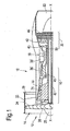
- a fan outlet guide vane 28 as shown in figure 2 , comprises an aerofoil shaped body 60 which has a leading edge 62, a trailing edge 64, a concave surface 66, a convex surface 68, a radially inner end 70 and a radially outer end 72.
- the fan outlet guide vane 28 has an internal cavity 74 and the internal cavity 74 may be hollow or may be filled with a vibration damping medium.
- the fan outlet guide vane 28 has been manufactured using the diffusion bonding and superplastic forming process according to the present invention.
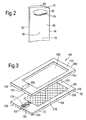
- two titanium alloy workpieces 100 and 102 are assembled into a stack 104.
- the titanium alloy workpiece 100 has a first surface 106 and a second surface 108 and the titanium alloy workpiece 102 has a third surface 110 and a fourth surface 112.
- the first surface 106 is a flat surface and the third surface 110 is a flat surface.
- the first surface 106 of the titanium alloy workpiece 100 is arranged to abut the third surface 110 of the titanium alloy workpiece 102.
- the titanium alloy workpieces 100 and 102 taper, increase in thickness, from end 116 to end 114.
- the titanium alloy workpieces 100 and 102 are produced by cutting an original parallelepiped block of titanium alloy long an inclined plane to form the two longitudinally tapering titanium alloy workpieces 100 and 102 as described more fully in our UK patent GB2306353B .
- the titanium alloy workpieces 100 and 102 may be separate blocks of titanium alloy.
- the titanium alloy workpiece 100 Prior to assembling the titanium alloy workpieces 100 and 102 into the stack 104, the titanium alloy workpiece 100 is machined in a region 118, centrally of the second surface 108 of the titanium alloy workpiece 100 and the titanium alloy workpiece 102 is machined in a region 120, centrally of the fourth surface 112 of the titanium alloy workpiece 102.
- the regions 118 and 120 are contoured to produce a variation in the mass distribution of the fan outlet guide vane 28 from leading edge 62 to trailing edge 64 and from radially inner end 70 to radially outer end 72 by varying the depth of machining.
- the machining of the regions 118 and 120 of the titanium alloy workpieces 100 and 102 respectively is by milling, electrochemical machining, chemical machining, electro-discharge machining or any other suitable machining process.
- the abutting surfaces, the first surface 106 and the third surface 110 of the titanium alloy workpieces 100 and 102 respectively are prepared for diffusion bonding by chemical cleaning.
- a stop off material 122 to prevent diffusion bonding is applied in a predetermined pattern on one of the abutting surfaces 106 and 110, in this example the first surface 106 of the titanium alloy workpiece 100, the predetermined pattern of stop off material 122 is spaced from the edges of the first surface 106 of the titanium alloy workpiece 100.
- a stop off material 124 to prevent diffusion bonding is applied in a predetermined position on one of the abutting surfaces 106 and 110, in this example the first surface 106 of the titanium alloy workpiece 100, the predetermined position extends from the predetermined pattern of stop of material 122 on the first surface 106 of the titanium alloy workpiece 100 towards one edge 128 of the first surface 106 of the titanium alloy workpiece 100.
- the edge 128 in this example is at the end 114.
- the stop off material 122 and 124 may comprise powdered yttria in a binder and solvent e.g. the stop off known as "Stopyt 62A".
- the predetermined pattern of stop off material 122 is provided to define the internal cavity 74 in the finished fan outlet guide vane 28.
- the stop off material 124 is provided to define a flow path, an inflation passage, for a fluid to flow to the predetermined pattern of stop off material 122 in order to allow the fluid to superplastically inflate the titanium alloy workpieces 100 and 102 away from each other.
- a first recess 130 is machined in a second predetermined position on the second surface 108 of the titanium alloy workpiece 100 and the recess 130 extends towards the edge 128 of the titanium alloy workpiece 100.
- a second recess 132 is machined in a third predetermined position on the fourth surface 112 of the titanium alloy workpiece 102 and the second recess extends towards a corresponding edge 134 of the third surface 110 of the titanium alloy workpiece 102.
- the edge 134 in this example is at the end 114.
- the first and second recesses 130 and 132 may be any suitable shape in cross-section, but it is preferred that they are a sector of a circle and that the depth of the first and second recesses 130 and 132 are the same such that an inflation passage with a lenticular cross-section is formed after diffusion bonding and superplastic forming, as shown in figure 9 .
- the titanium alloy workpiece 100 and the titanium alloy workpiece 102 are assembled into the stack 104 such that the first surface 106 of the titanium alloy workpiece 100 faces the third surface 110 of the titanium alloy workpiece 102 and such that the first recess 130 in the second predetermined position on the second surface 108 of the titanium alloy workpiece 100 and the second recess 132 in the third predetermined position on the fourth surface 112 of the titanium alloy workpiece 102 are aligned with the stop off material 124 arranged in the predetermined position on the first surface 106 of the titanium alloy workpiece 100.
- the stop off material 124, the first recess 130 and the second recess 132 are arranged in a plane P extending perpendicularly to the planes of the titanium alloy workpieces 100 and 102.
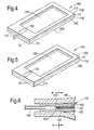
- the edges of the titanium alloy workpiece 100 and the edges of the titanium alloy workpiece 102 are sealed together to form a sealed assembly 140 as shown in figure 4 .
- the edges of the titanium alloy workpiece 100 and the edges of the titanium alloy workpiece 102 are welded together to form a sealed assembly 140 except for an evacuation pipe 143 which is connected to the sealed assembly 140 and the pipe 143 is welded around its periphery to the titanium alloy workpieces 100 and 102.
- the evacuation pipe 143 locates in part circular slots 131 in the edges 128 and 134 of the first and second titanium alloy workpieces 100 and 102 respectively.
- the pipe 143 interconnects with the stop off material 124 and 122 between the titanium alloy workpieces 100 and 102, in other words the stop off material 124 extends towards the edge 128 as far as the part circular slot 131.
- the pipe 143 is connected to the end 114 at what will be the radially outer end of the fan outlet guide vane 28.
- the pipe 143 is connected to a vacuum pump, which is used to evacuate the interior of the sealed assembly 140.
- inert gas for example argon
- inert gas for example argon
- the evacuating and supplying of inert gas to the interior of the sealed assembly 140 may be repeated several times to ensure that most, or substantially all, traces of oxygen are removed from the interior of the sealed assembly 140 and the sealed assembly 140 is finally evacuated.
- the evacuated sealed assembly 140 is then placed in an oven.
- the sealed assembly 140 is then heated at a temperature of 250°C to 350°C to evaporate the binder from the stop off material 122 and 124.
- the interior of the sealed assembly 140 is continuously evacuated to remove the binder from between the titanium alloy workpieces 100 and 102.
- the pipe 143 is sealed so that there is a vacuum in the sealed assembly 140.
- the sealed assembly 140 is transferred to an autoclave, or a HIP vessel, and the sealed assembly 140 is heated and externally pressurised to diffusion bond the titanium alloy workpieces 100 and 102 together in areas other than the predetermined areas, e.g. the stop off material 122 and 124 in the predetermined pattern and the predetermined position, to form a sealed integral structure 142 as shown in figure 5 .
- the sealed assembly 140 is heated to a temperature greater than 850°C and the pressure is greater than 20 atmospheres, 294lbs per square inch (20.26 x 10 5 Nm -2 ) and held at that temperature and pressure for a predetermined time.
- the temperature is between 900°C and 950°C and the pressure is between 294lbs per square inch (20.26 x 10 5 Nm -2 ) and 441lbs per square inch (30.39 x 10 5 Nm -2 ).
- the sealed integral structure 142 may then be placed in a hot creep forming die and hot creep formed, or twisted, to produce an aerofoil shape. During the hot creep forming process the sealed integral structure 142 is heated to a temperature of 740°C.
- the sealed integral structure 142 is placed in a superplastic forming die 146, as shown in figures 6 and 7 , and an inflation pipe 144 is connected to the stop off material 124 in the first predetermined position on the first surface 106 of the titanium alloy workpiece 100 of the sealed integral structure 142.
- the inflation pipe 144 may be positioned in an aperture drilled in the appropriate end of the sealed integral structure 142.
- the sealed integral structure 142 is heated and a fluid, an inert gas for example argon, is supplied through the inflation pipe 144 to internally pressurise the sealed integral structure 142 to cause the titanium alloy workpiece 100 and/or the titanium alloy workpiece 102, where the stop off material 124 was arranged in the predetermined pattern and the first recess 130 was arranged in the second predetermined position and the second recess 132 in the third predetermined position, to be hot formed onto, to abut, the surfaces of the superplastic forming die 146 to create an inflation passage 148 within the sealed integral structure 142 as shown in figures 8, 9 and 10 .
- a fluid an inert gas for example argon
- the sealed integral structure 142 is heated and internally pressurised to cause the titanium alloy workpiece 100 and/or the titanium alloy workpiece 102 where the stop off material 122 was arranged in the predetermined pattern to be superplastically formed onto the surfaces of the superplastic forming die 146 to create a hollow fan outlet guide vane 28 as shown in figure 2 .
- the sealed integral structure 142 is heated to a temperature greater than 850°C, preferably the temperature is between 900°C and 950°C.
- the inflation passage 148 is formed during the supply of high pressure inflation gas to the interior of the sealed integral structure 142.
- the fan outlet guide vane 28 instead of machining a first recess 130 in a second predetermined position on the second surface 108 of the titanium alloy workpiece 100 and the recess 130 extends towards the edge 128 of the titanium alloy workpiece 100 it is equally possible to machine the first recess 130 in a second predetermined position on the first surface 106 of the titanium alloy workpiece 100.
- the stop off material 124 in the first predetermined position is located on the first surface 106 in the first recess 130 or is located on the third surface 110 in the second recess 132.
- the titanium alloy workpiece 100 and the titanium alloy workpiece 102 in the region of the first and second recesses 130 and 132 are superplastically formed towards each other, but are prevented from diffusion bonding due to the stop off material 124, such that a first recess 130 and a second recess 132 are formed in the second surface 108 and fourth surface 112 of the titanium alloy workpieces 100 and 102 respectively during the diffusion bonding of the titanium alloy workpieces 100 and 102. Thereafter during superplastic forming the first recess 130 and the second recess 132 are reformed to form the inflation passage.
- the first recess 130 may be machined in a second predetermined position on the first surface 106 of the titanium alloy workpiece 100 and the second recess 132 may be machined in a third predetermined position on the fourth surface 112 of the titanium alloy workpiece 102.
- a fan blade 26, as shown in figure 11 comprises an aerofoil shaped body 80 which has a leading edge 82, a trailing edge 84, a concave surface 86, a convex surface 88, a root 90 at a radially inner end and a tip 92 at a radially outer end.
- the fan blade 26 has an internal cavity 94 and the internal cavity 94 may be hollow or may be filled with a vibration damping medium.
- the fan blade 26 has been manufactured using two titanium alloy workpieces and using the diffusion bonding and superplastic forming process according to the present invention as described with reference to figures 2 to 5 .
- the titanium alloy workpieces 100 and 102 taper, increase in thickness, from end 114 to end 116 and the pipe 143 is connected to the end 114 at what will be the radially outer end of the fan blade 26.
- a fan blade 26B as shown in figure 12 , comprises an aerofoil shaped body 80B which has a leading edge 82B, a trailing edge 84B, a concave surface 86B, a convex surface 88B, a root 90B at a radially inner end and a tip 92B at a radially outer end.
- the fan blade 26B has a warren girder structure 96B which defines a plurality of internal cavities 94B and the internal cavities 94B may be hollow or may be filled with a vibration damping medium.
- the fan blade 26B has been manufactured using three titanium alloy workpieces 100B, 101B and 102B, as shown in figure 13 , and using the diffusion bonding and superplastic forming process according to the present invention.
- three titanium alloy workpieces 100B, 101B and 102B it is necessary to provide stop off material 122B in a predetermined pattern between the facing surfaces of a first titanium alloy workpiece 100B and a second titanium alloy workpiece 101B and to provide stop off material in a further predetermined pattern between the facing surfaces of the second titanium alloy workpiece 101B and a third titanium alloy workpiece 102B.
- stop off material 124B in a predetermined position between the facing surfaces of the first titanium alloy workpiece 100B and the second titanium alloy workpiece 101 B and to provide a first recess 130B in a second predetermined position on the outer surface of the first titanium alloy workpiece 100B.
- stop off material 124B in a predetermined position between the facing surfaces of the first titanium alloy workpiece 100B and the second titanium alloy workpiece 101 B and to provide a first recess in a second predetermined position on the inner surface of the first titanium alloy workpiece 100B.
- stop off material in a predetermined position between the facing surfaces of the second titanium alloy workpiece 101B and the third titanium alloy workpiece 102B and to provide a second recess 132B in a third predetermined position on the outer surface of the third titanium alloy workpiece 102B.
- stop off material in a predetermined position between the facing surfaces of the second titanium alloy workpiece 101B and the third titanium alloy workpiece 102B and to provide a second recess in a third predetermined position on the inner surface of the third titanium alloy workpiece 102B.
- the titanium alloy workpieces 100B and 102B taper, increase in thickness, from end 114B to end 116B and the pipe is connected to the end 114B at what will be the radially outer end of the fan blade 26B.
- Figure 14 illustrates an alternative embodiment of the present invention after the diffusion bonding step, in which a first recess 130 is provided on the second surface of the first titanium alloy workpiece 100 but a second recess is not provided on the fourth surface of the second titanium alloy workpiece 102.
- Figure 15 illustrates this embodiment after the superplastic forming step and shows the resulting inflation passage 148.
- Figure 16 illustrates a further embodiment of the present invention before the diffusion bonding step, in which a first recess 130 is provided on the first surface 106 of the first titanium alloy workpiece 100 and a second recess 132 is provided on the third surface 110 of the second titanium alloy workpiece 102 and the stop off material 124 is provided on the surface of the first and/or the second recesses 130 and 132.
- Figure 17 illustrates this embodiment after the diffusion bonding step and shows that the first recess 130 has moved to the second surface 108 of the first titanium alloy workpiece 100 and the second recess 132 has moved to the fourth surface 112 of the second titanium alloy workpiece 102.
- Figure 18 illustrates this embodiment after the superplastic forming step and shows the resulting inflation passage 148.
- FIG 19 illustrates another embodiment of the present invention and shows two titanium alloy workpieces 100C and 102C are assembled into a stack 104C.
- the titanium alloy workpiece 100C has a first surface 106C and a second surface 108C and the titanium alloy workpiece 102C has a third surface 110C and a fourth surface 112C.
- the first surface 106C is a flat surface and the third surface 110C is a flat surface.
- the first surface 106C of the titanium alloy workpiece 100C is arranged to abut the third surface 110C of the titanium alloy workpiece 102C.
- the titanium alloy workpieces 100C and 102C taper, increase in thickness, from end 116C to end 114C.
- a stop off material 122C in a predetermined pattern between the facing surfaces of a first titanium alloy workpiece 100C and a second titanium alloy workpiece 102C It is also necessary to provide stop off material 124C in a predetermined position between the facing surfaces of the first titanium alloy workpiece 100C and the second titanium alloy workpiece 102C and to provide a first recess 130C in a second predetermined position on the second surface 108C of the first titanium alloy workpiece 100C.
- first recess 130C extends along the second surface 108C of the first titanium alloy workpiece 100C towards the edge at the end 114C of the first titanium alloy workpiece 100C from a position in the second surface 108C corresponding to a position on the first surface 106C of the first titanium alloy workpiece 100C having stop off material 122C.
- an inflation slot 131C extends along the third surface 110C of the second titanium alloy workpiece 102C towards the edge at the end 114C of the second titanium alloy workpiece 102C from a position in the third surface 110C corresponding to a position on the first surface 106C of the first titanium alloy workpiece 100C having stop off material 122C.
- the inflation slot 131C has a very small cross-sectional area and has a depth of about 1.5mm and a width of about 1.5mm.
- the first surface 106C of the first titanium alloy workpiece 100C and the third surface 110C of the second titanium alloy workpiece 102C are provided with part circular slots 132C and 133C respectively at the edges at the end 114C of the first titanium alloy workpieces 100C and 102C.
- the part circular slots 132C and 133C are arranged to receive an end of a pipe used to evacuate the sealed assembly 104C before diffusion bonding.
- the inflation slot 131C and the stop off material 124C extend along the third surface 110C of the second titanium alloy workpiece 102C and the first surface 106C of the first titanium alloy workpiece 100C respectively towards the edge at the end 114C of the first titanium alloy workpiece 100C to reach the part circular slots 133C and 132C respectively.
- Figure 20 shows a cross-sectional view through the sealed assembly 140C showing the arrangement of the first recess 130C, the inflation slot 131C and the stop off material 124C.
- Figure 21 shows a cross-sectional view through the sealed integral structure 142C after diffusion bonding and superplastic forming and shows the resulting inflation passage 148C.
- stop off material 124C in a predetermined position between the facing surfaces of the first titanium alloy workpiece 100C and the second titanium alloy workpiece 102C and to provide a first recess in a second predetermined position on the first surface 106C of the first titanium alloy workpiece 100C.
- the advantage of the present invention is that it provides an increased cross-sectional area inflation passage to supply inflation gas to the interior of the sealed integral assembly for superplastic forming of the sealed integral assembly.
- the present invention also has the advantage that it provides an increased cross-sectional area inflation passage to allow inflation gas to exit the interior of the sealed integral assembly after superplastic forming of the sealed integral assembly.
- the present invention also has the advantage that it provides an increased cross-sectional area inflation passage to allow gas to enter the interior of the sealed integral assembly during cooling after superplastic forming of the sealed integral assembly to prevent an under formed profile.
- the present invention reduces non-conformance of diffusion bonded and superplastically formed components, reduces the forming time of diffusion bonded and superplastically formed components, increases the process capability and minimises implementation costs.
- a further advantage of providing a recess on an internal surface of a titanium alloy workpiece is that it provides an increased cross-sectional area passage for removal of the binder during bake out of the binder from the stop off material.
- a disadvantage of providing a recess on an internal surface of the titanium alloy workpiece is that it increases the risk of damaging the surface of the titanium alloy workpiece that is to be diffusion bonded.
- a recess may be provided in a second predetermined position on the first surface of the first metal workpiece, the second surface of the first metal workpiece, the third surface of the second metal workpiece or the fourth surface of the second metal workpiece, the recess extending towards the same edge of the first metal workpiece or a corresponding edge of the second metal workpiece.
Claims (14)
- Procédé de fabrication d'un article (28) par soudage par diffusion et formage superplastique, comprenant les étapes consistant à :a) utiliser au moins une première pièce à usiner métallique (100) et une deuxième pièce à usiner métallique (102), la première pièce à usiner métallique (100) ayant une première surface (106) et une deuxième surface (108), la deuxième pièce à usiner métallique (102) ayant une troisième surface (110) et une quatrième surface (112),b) appliquer du stop-off (122) pour empêcher le soudage par diffusion dans un motif prédéterminé sur la première surface (106) de la première pièce à usiner métallique (100), le motif prédéterminé étant espacé des bords de la première surface (106) de la première pièce à usiner métallique (100),c) appliquer du stop-off (124) pour empêcher le soudage par diffusion dans une position prédéterminée sur la première surface (106) de la première pièce à usiner métallique (100) ou la troisième surface (110) de la deuxième pièce à usiner métallique (102), la position prédéterminée s'étendant du motif prédéterminé de stop-off (122) sur la première surface (106) de la première pièce à usiner métallique (100) vers un bord de la première surface (106) de la première pièce à usiner métallique (100),d) utiliser un évidement (130) dans une deuxième position prédéterminée sur la première surface (106) de la première pièce à usiner métallique (100), la deuxième surface (108) de la première pièce à usiner métallique (100), la troisième surface (110) de la deuxième pièce à usiner métallique (102) ou la quatrième surface (112) de la deuxième pièce à usiner métallique (102), l'évidement (130) s'étendant vers le même bord de la première pièce à usiner métallique (100) ou vers un bord correspondant de la deuxième pièce à usiner métallique (102),e) assembler au moins la première pièce à usiner métallique (100) et la deuxième pièce à usiner métallique (102) dans une pile (104) de sorte que la première surface (106) de la première pièce à usiner métallique (100) fasse face à la troisième surface (110) de la deuxième pièce à usiner métallique (102) et que l'évidement (130) dans la deuxième position prédéterminée sur la première surface (106) de la première pièce à usiner métallique (100), la deuxième surface (108) de la première pièce à usiner métallique (100), la troisième surface (110) de la deuxième pièce à usiner métallique (102) ou la quatrième surface (112) de la deuxième pièce à usiner métallique (102) soit aligné avec le stop-off (124) disposé dans la position prédéterminée sur la première surface (106) de la première pièce à usiner métallique (100) ou soit aligné avec le stop-off (124) disposé dans la position prédéterminée sur la troisième surface (110) de la deuxième pièce à usiner métallique (102),f) rendre étanche les bords de la première pièce à usiner métallique (100) sur les bords de la deuxième pièce à usiner métallique (102) pour former un ensemble étanche (140), excepté pour un tuyau d'évacuation (143) qui est relié à l'ensemble étanche (140),g) évacuer l'intérieur de l'ensemble étanche (140),h) chauffer et mettre sous pression externe l'ensemble étanche (140) pour souder par diffusion les première et deuxième pièces à usiner métalliques (100, 102) ensemble dans des zones autres que le motif prédéterminé (122) et la position prédéterminée (124) pour former une structure monobloc étanche (142),i) relier un tuyau de gonflage (144) au stop-off (124) dans la première position prédéterminée sur la première surface (106) de la première pièce à usiner métallique (100) ou la troisième surface (110) de la deuxième pièce à usiner métallique (102) de la structure monobloc étanche (142),j) chauffer et mettre sous pression interne la structure monobloc étanche (142) pour amener la première pièce à usiner métallique (100), ou la deuxième pièce à usiner métallique (102), où le stop-off (124) était disposé dans la position prédéterminée et l'évidement (130) était disposé dans la deuxième position prédéterminée, à être formée à chaud pour créer un passage de gonflage (148) à l'intérieur de la structure monobloc étanche (142), etk) chauffer et mettre sous pression interne la structure monobloc étanche (142) pour amener la première pièce à usiner métallique (100) et/ou la deuxième pièce à usiner métallique (102) où le stop-off (122) était disposé dans le motif prédéterminé à être formée de manière superplastique pour créer un article métallique creux (28).
- Procédé selon la revendication 1, dans lequel l'étape d) comprend l'étape consistant à utiliser un premier évidement (130) dans une deuxième position prédéterminée sur la deuxième surface (108) de la première pièce à usiner métallique (100) et un second évidement (132) dans une troisième position prédéterminée sur la quatrième surface (112) de la deuxième pièce à usiner métallique (102), le premier évidement (130) s'étendant vers le même bord de la première pièce à usiner métallique (100) et le second évidement (132) s'étendant vers un bord correspondant de la deuxième pièce à usiner métallique (102), l'étape e) comprend l'étape consistant à assembler au moins la première pièce à usiner métallique (100) et la deuxième pièce à usiner métallique (102) dans la pile (104) de sorte que le premier évidement (130) dans la deuxième position prédéterminée sur le deuxième surface (108) de la première pièce à usiner métallique (100) et le second évidement (132) dans la quatrième surface (112) de la deuxième pièce à usiner métallique (102) soient alignés avec le stop-off (124) disposé dans la position prédéterminée sur la première surface (106) de la première pièce à usiner métallique (100) et l'étape j) comprend l'étape consistant à chauffer et mettre sous pression interne la structure monobloc étanche (142) pour amener la première pièce à usiner métallique (100) et la deuxième pièce à usiner métallique (102), où le stop-off (124) était disposé dans la position prédéterminée, le premier évidement (130) était disposé dans la deuxième position prédéterminée et le second évidement (132) était disposé dans la troisième position prédéterminée, à être formée à chaud pour créer un passage de gonflage (148) à l'intérieur de la structure monobloc étanche (142).
- Procédé selon la revendication 1, dans lequel l'étape d) comprend l'étape consistant à utiliser un premier évidement (130) dans une deuxième position prédéterminée sur la première surface (106) de la première pièce à usiner métallique (100) et un second évidement (132) dans une troisième position prédéterminée sur la troisième surface (110) de la deuxième pièce à usiner métallique (102), le premier évidement (130) s'étendant vers le même bord de la première pièce à usiner métallique (100) et le second évidement (132) s'étendant vers un bord correspondant de la deuxième pièce à usiner métallique (102), l'étape e) comprend l'étape consistant à assembler au moins la première pièce à usiner métallique (100) et la deuxième pièce à usiner métallique (102) dans la pile (104) de sorte que le premier évidement (130) dans la deuxième position prédéterminée sur la première surface (106) de la première pièce à usiner métallique (100) et le second évidement (132) dans la troisième surface (110) de la deuxième pièce à usiner métallique (102) soient alignés avec le stop-off (124) disposé dans la position prédéterminée sur la première surface (106) de la première pièce à usiner métallique (100) et l'étape j) comprend l'étape consistant à chauffer et mettre sous pression interne la structure monobloc étanche (140) pour amener la première pièce à usiner métallique (100) et la deuxième pièce à usiner métallique (102), où le stop-off (124) était disposé dans la position prédéterminée, le premier évidement (130) était disposé dans la deuxième position prédéterminée et le second évidement (132) était disposé dans la troisième position prédéterminée, à être formée à chaud pour créer un passage de gonflage (148) à l'intérieur de la structure monobloc étanche (142).
- Procédé selon l'une quelconque des revendications 1 à 3, dans lequel l'étape a) comprend l'étape consistant à utiliser une troisième pièce à usiner métallique, la troisième pièce à usiner métallique ayant une cinquième surface et une sixième surface, l'étape b) comprend l'étape consistant à appliquer un stop-off pour empêcher le soudage par diffusion dans un motif prédéterminé sur la troisième surface de la deuxième pièce à usiner métallique, le motif prédéterminé étant espacé des bords de la troisième surface de la deuxième pièce à usiner métallique, l'étape e) comprend l'étape consistant à assembler la première pièce à usiner métallique, la deuxième pièce à usiner métallique et la troisième pièce de travail métallique dans une pile de sorte que la première surface de la première pièce à usiner métallique fasse face à la cinquième surface de la troisième pièce à usiner métallique, la sixième surface de la troisième pièce à usiner métallique fasse face à la troisième surface de la deuxième pièce à usiner métallique et l'évidement dans la deuxième position prédéterminée sur la première surface de la première pièce à usiner métallique, la deuxième surface de la première pièce à usiner métallique, la troisième surface de la deuxième pièce à usiner métallique ou la quatrième surface de la deuxième pièce à usiner métallique soit aligné avec le stop-off disposé dans la position prédéterminée sur la première surface de la première pièce à usiner métallique.
- Procédé selon l'une quelconque des revendications 1 à 4, dans lequel l'article (28) est une pale de soufflante ou un aubage directeur de sortie de soufflante.
- Procédé selon l'une quelconque des revendications 1 à 4, dans lequel l'article (28) est un échangeur de chaleur, une pale de compresseur ou une aube de compresseur.
- Procédé selon l'une quelconque des revendications 1 à 6, dans lequel la première pièce à usiner métallique (100), la deuxième pièce à usiner métallique (102) ou la troisième pièce à usiner métallique (101 B) comprend un alliage de titane.
- Procédé selon la revendication 7, dans lequel l'alliage de titane comprend 6 % en poids de vanadium, 4 % en poids d'aluminium et le reste en titane, ajouts élémentaires mineurs et impuretés accidentelles.
- Procédé selon la revendication 1, dans lequel l'étape d) comprend l'étape consistant à utiliser un évidement (130) dans une deuxième position prédéterminée sur la première surface (106) de la première pièce à usiner métallique (100), l'évidement (130) s'étendant vers le même bord de la première pièce à usiner métallique (100).
- Procédé selon la revendication 1, dans lequel l'étape d) comprend l'étape consistant à utiliser un évidement (130) dans une deuxième position prédéterminée sur la deuxième surface (108) de la première pièce à usiner métallique (100), l'évidement (130) s'étendant vers le même bord de la première pièce à usiner métallique (100).
- Procédé selon l'une quelconque des revendications 1 à 10, dans lequel l'étape h) comprend les étapes consistant à chauffer à une température supérieure à 850 °C et à appliquer une pression supérieure à 20,26 x 10⁵ Nm-2.
- Procédé selon la revendication 11, dans lequel l'étape h) comprend les étapes consistant à chauffer à une température comprise entre 900 et 950 °C et à appliquer une pression comprise entre 20,26 x 10⁵ Nm-2 et 30,39 x 10⁵ Nm-2.
- Procédé selon l'une quelconque des revendications 1 à 12, dans lequel l'étape j) et l'étape k) comprennent l'étape consistant à chauffer à une température supérieure à 850 °C.
- Procédé selon la revendication 13, dans lequel l'étape j) et l'étape k) comprennent l'étape consistant à chauffer à une température comprise entre 900 et 950 °C.
Applications Claiming Priority (1)
| Application Number | Priority Date | Filing Date | Title |
|---|---|---|---|
| GB1009299.7A GB2481000B (en) | 2010-06-03 | 2010-06-03 | A method of manufacturing an article by diffusion bonding and superplastic forming |
Publications (3)
| Publication Number | Publication Date |
|---|---|
| EP2392423A2 EP2392423A2 (fr) | 2011-12-07 |
| EP2392423A3 EP2392423A3 (fr) | 2013-06-12 |
| EP2392423B1 true EP2392423B1 (fr) | 2015-02-25 |
Family
ID=42471101
Family Applications (1)
| Application Number | Title | Priority Date | Filing Date |
|---|---|---|---|
| EP11165114.7A Not-in-force EP2392423B1 (fr) | 2010-06-03 | 2011-05-06 | Procédé de fabrication d'un article par soudage par diffusion et formage superplastique |
Country Status (4)
| Country | Link |
|---|---|
| US (1) | US8162202B2 (fr) |
| EP (1) | EP2392423B1 (fr) |
| GB (1) | GB2481000B (fr) |
| SG (1) | SG176412A1 (fr) |
Families Citing this family (8)
| Publication number | Priority date | Publication date | Assignee | Title |
|---|---|---|---|---|
| GB0412915D0 (en) * | 2004-06-10 | 2004-07-14 | Rolls Royce Plc | Method of making and joining an aerofoil and root |
| GB201414497D0 (en) * | 2014-08-15 | 2014-10-01 | Rolls Royce Plc | A method of forming an inflated aerofoil |
| CN107283008A (zh) | 2016-03-30 | 2017-10-24 | 通用电气公司 | 电火花加工装置及利用电极组件对工件进行加工的方法 |
| CN106078112B (zh) * | 2016-07-21 | 2018-07-20 | 滁州南钢盛达实业有限公司 | 一种h型钢的生产工艺 |
| US10480528B2 (en) * | 2016-08-10 | 2019-11-19 | Rolls-Royce Plc | Superplastic forming |
| GB201710651D0 (en) * | 2017-07-03 | 2017-08-16 | Rolls Royce Plc | Manufacturing assembly and method |
| DE102021213010B4 (de) * | 2021-11-18 | 2023-06-15 | Ipu Ingenieurgesellschaft Braunschweig Mbh | Verfahren zur formwerkzeugfreien Herstellung eines reliefierten Bauteils und reliefiertes Bauteil |
| CN114346396A (zh) * | 2021-12-28 | 2022-04-15 | 北京航星机器制造有限公司 | 一种双层口盖壁板超塑成形扩散连接模具和方法 |
Family Cites Families (9)
| Publication number | Priority date | Publication date | Assignee | Title |
|---|---|---|---|---|
| US4526312A (en) * | 1979-12-10 | 1985-07-02 | Rockwell International Corporation | Low cost method of making superplastically formed and diffusion bonded structures |
| US4304350A (en) * | 1980-01-07 | 1981-12-08 | Grumman Aerospace Corporation | Method of pressurization system for superplastic forming and diffusion bonding |
| US5479705A (en) * | 1992-05-01 | 1996-01-02 | Rolls-Royce Plc | Method of manufacturing an article by superplastic forming and diffusion bonding |
| US5275325A (en) * | 1992-12-10 | 1994-01-04 | Grumman Aerospace Corporation | Pressurization system inlet assembly for superplastic forming and diffusion bonding |
| GB2289429B (en) * | 1994-05-10 | 1997-01-22 | Rolls Royce Plc | Hollow component manufacture |
| GB2306353B (en) | 1995-10-28 | 1998-10-07 | Rolls Royce Plc | A method of manufacturing a blade |
| US5692406A (en) * | 1996-09-27 | 1997-12-02 | Mcdonnell Douglas Corporation | Gas inlet for a superplastic forming die and method of use |
| GB2360236B (en) | 2000-03-18 | 2003-05-14 | Rolls Royce Plc | A method of manufacturing an article by diffusion bonding and superplastic forming |
| GB0318937D0 (en) * | 2003-08-13 | 2003-09-17 | Rolls Royce Plc | A method of manufacturing an article by diffusion bonding and superplastic forming |
-
2010
- 2010-06-03 GB GB1009299.7A patent/GB2481000B/en not_active Expired - Fee Related
-
2011
- 2011-05-06 EP EP11165114.7A patent/EP2392423B1/fr not_active Not-in-force
- 2011-05-06 US US13/102,483 patent/US8162202B2/en active Active
- 2011-05-30 SG SG2011039062A patent/SG176412A1/en unknown
Also Published As
| Publication number | Publication date |
|---|---|
| US8162202B2 (en) | 2012-04-24 |
| GB2481000A (en) | 2011-12-14 |
| EP2392423A3 (fr) | 2013-06-12 |
| US20110297734A1 (en) | 2011-12-08 |
| EP2392423A2 (fr) | 2011-12-07 |
| SG176412A1 (en) | 2011-12-29 |
| GB201009299D0 (en) | 2010-07-21 |
| GB2481000B (en) | 2012-08-08 |
Similar Documents
| Publication | Publication Date | Title |
|---|---|---|
| EP2392423B1 (fr) | Procédé de fabrication d'un article par soudage par diffusion et formage superplastique | |
| EP1669144B1 (fr) | Procédé de production de pièces métalliques par métallurgie des poudres | |
| EP1508400B1 (fr) | Procédé de fabrication d'un objet par soudage par diffusion et formage superplastique | |
| US6467168B2 (en) | Method of manufacturing an article by diffusion bonding and superplastic forming | |
| US7025568B2 (en) | Turbomachine aerofoil | |
| EP1338353B1 (fr) | Procédé de fabrication d'un article pour soudage par diffusion et formage superplastique | |
| EP3164605B1 (fr) | Fabrication d'un rouet de turbomachine par assemblage d'une pluralité d'éléments tubulaires | |
| US7594325B2 (en) | Aerofoil and a method of manufacturing an aerofoil | |
| EP3058177B1 (fr) | Procédé de formation d'un composant d'un moteur à turbine à gaz | |
| US5323536A (en) | Method of manufacturing an article by superplastic forming and diffusion bonding | |
| EP3441573B1 (fr) | Pale de ventilateur creuse en titane soudée par faisceau d'énergie à l'arrière de la cavité | |
| US6802122B2 (en) | Method of manufacturing an article | |
| US6418619B1 (en) | Method of manufacturing an article by superplastic forming and diffusion bonding | |
| US6871398B2 (en) | Method of manufacturing an article by diffusion bonding | |
| US5581882A (en) | Method of manufacturing an article by superplastic forming and diffusion bonding | |
| EP2226134A2 (fr) | Procédé de fabrication d'une surface portante | |
| US5457884A (en) | Method of manufacturing an article by superplastic forming and diffusion bonding | |
| EP0908263B1 (fr) | Procédé de fabrication d'une pièce par soudage par diffusion |
Legal Events
| Date | Code | Title | Description |
|---|---|---|---|
| AK | Designated contracting states |
Kind code of ref document: A2 Designated state(s): AL AT BE BG CH CY CZ DE DK EE ES FI FR GB GR HR HU IE IS IT LI LT LU LV MC MK MT NL NO PL PT RO RS SE SI SK SM TR |
|
| AX | Request for extension of the european patent |
Extension state: BA ME |
|
| PUAI | Public reference made under article 153(3) epc to a published international application that has entered the european phase |
Free format text: ORIGINAL CODE: 0009012 |
|
| PUAL | Search report despatched |
Free format text: ORIGINAL CODE: 0009013 |
|
| AK | Designated contracting states |
Kind code of ref document: A3 Designated state(s): AL AT BE BG CH CY CZ DE DK EE ES FI FR GB GR HR HU IE IS IT LI LT LU LV MC MK MT NL NO PL PT RO RS SE SI SK SM TR |
|
| AX | Request for extension of the european patent |
Extension state: BA ME |
|
| RIC1 | Information provided on ipc code assigned before grant |
Ipc: B21D 26/055 20110101ALI20130506BHEP Ipc: B21D 26/059 20110101ALI20130506BHEP Ipc: B21D 53/78 20060101AFI20130506BHEP Ipc: B21D 26/021 20110101ALI20130506BHEP Ipc: B23P 15/04 20060101ALI20130506BHEP Ipc: B23K 20/00 20060101ALI20130506BHEP |
|
| 17P | Request for examination filed |
Effective date: 20131206 |
|
| RBV | Designated contracting states (corrected) |
Designated state(s): AL AT BE BG CH CY CZ DE DK EE ES FI FR GB GR HR HU IE IS IT LI LT LU LV MC MK MT NL NO PL PT RO RS SE SI SK SM TR |
|
| RBV | Designated contracting states (corrected) |
Designated state(s): AL AT BE BG CH CY CZ DE DK EE ES FI FR GR HR HU IE IS IT LI LT LU LV MC MK MT NL NO PL PT RO RS SE SI SK SM TR |
|
| 17Q | First examination report despatched |
Effective date: 20140115 |
|
| GRAP | Despatch of communication of intention to grant a patent |
Free format text: ORIGINAL CODE: EPIDOSNIGR1 |
|
| INTG | Intention to grant announced |
Effective date: 20141106 |
|
| GRAS | Grant fee paid |
Free format text: ORIGINAL CODE: EPIDOSNIGR3 |
|
| GRAA | (expected) grant |
Free format text: ORIGINAL CODE: 0009210 |
|
| AK | Designated contracting states |
Kind code of ref document: B1 Designated state(s): AL AT BE BG CH CY CZ DE DK EE ES FI FR GR HR HU IE IS IT LI LT LU LV MC MK MT NL NO PL PT RO RS SE SI SK SM TR |
|
| REG | Reference to a national code |
Ref country code: CH Ref legal event code: EP |
|
| REG | Reference to a national code |
Ref country code: IE Ref legal event code: FG4D |
|
| REG | Reference to a national code |
Ref country code: DE Ref legal event code: R096 Ref document number: 602011013886 Country of ref document: DE Effective date: 20150409 |
|
| REG | Reference to a national code |
Ref country code: AT Ref legal event code: REF Ref document number: 711480 Country of ref document: AT Kind code of ref document: T Effective date: 20150415 |
|
| REG | Reference to a national code |
Ref country code: NL Ref legal event code: VDEP Effective date: 20150225 |
|
| REG | Reference to a national code |
Ref country code: AT Ref legal event code: MK05 Ref document number: 711480 Country of ref document: AT Kind code of ref document: T Effective date: 20150225 |
|
| REG | Reference to a national code |
Ref country code: LT Ref legal event code: MG4D |
|
| RAP2 | Party data changed (patent owner data changed or rights of a patent transferred) |
Owner name: ROLLS-ROYCE PLC |
|
| PG25 | Lapsed in a contracting state [announced via postgrant information from national office to epo] |
Ref country code: FI Free format text: LAPSE BECAUSE OF FAILURE TO SUBMIT A TRANSLATION OF THE DESCRIPTION OR TO PAY THE FEE WITHIN THE PRESCRIBED TIME-LIMIT Effective date: 20150225 Ref country code: LT Free format text: LAPSE BECAUSE OF FAILURE TO SUBMIT A TRANSLATION OF THE DESCRIPTION OR TO PAY THE FEE WITHIN THE PRESCRIBED TIME-LIMIT Effective date: 20150225 Ref country code: NO Free format text: LAPSE BECAUSE OF FAILURE TO SUBMIT A TRANSLATION OF THE DESCRIPTION OR TO PAY THE FEE WITHIN THE PRESCRIBED TIME-LIMIT Effective date: 20150525 Ref country code: HR Free format text: LAPSE BECAUSE OF FAILURE TO SUBMIT A TRANSLATION OF THE DESCRIPTION OR TO PAY THE FEE WITHIN THE PRESCRIBED TIME-LIMIT Effective date: 20150225 Ref country code: ES Free format text: LAPSE BECAUSE OF FAILURE TO SUBMIT A TRANSLATION OF THE DESCRIPTION OR TO PAY THE FEE WITHIN THE PRESCRIBED TIME-LIMIT Effective date: 20150225 Ref country code: SE Free format text: LAPSE BECAUSE OF FAILURE TO SUBMIT A TRANSLATION OF THE DESCRIPTION OR TO PAY THE FEE WITHIN THE PRESCRIBED TIME-LIMIT Effective date: 20150225 |
|
| PG25 | Lapsed in a contracting state [announced via postgrant information from national office to epo] |
Ref country code: IS Free format text: LAPSE BECAUSE OF FAILURE TO SUBMIT A TRANSLATION OF THE DESCRIPTION OR TO PAY THE FEE WITHIN THE PRESCRIBED TIME-LIMIT Effective date: 20150625 Ref country code: LV Free format text: LAPSE BECAUSE OF FAILURE TO SUBMIT A TRANSLATION OF THE DESCRIPTION OR TO PAY THE FEE WITHIN THE PRESCRIBED TIME-LIMIT Effective date: 20150225 Ref country code: RS Free format text: LAPSE BECAUSE OF FAILURE TO SUBMIT A TRANSLATION OF THE DESCRIPTION OR TO PAY THE FEE WITHIN THE PRESCRIBED TIME-LIMIT Effective date: 20150225 Ref country code: GR Free format text: LAPSE BECAUSE OF FAILURE TO SUBMIT A TRANSLATION OF THE DESCRIPTION OR TO PAY THE FEE WITHIN THE PRESCRIBED TIME-LIMIT Effective date: 20150526 Ref country code: AT Free format text: LAPSE BECAUSE OF FAILURE TO SUBMIT A TRANSLATION OF THE DESCRIPTION OR TO PAY THE FEE WITHIN THE PRESCRIBED TIME-LIMIT Effective date: 20150225 |
|
| PG25 | Lapsed in a contracting state [announced via postgrant information from national office to epo] |
Ref country code: NL Free format text: LAPSE BECAUSE OF FAILURE TO SUBMIT A TRANSLATION OF THE DESCRIPTION OR TO PAY THE FEE WITHIN THE PRESCRIBED TIME-LIMIT Effective date: 20150225 |
|
| PG25 | Lapsed in a contracting state [announced via postgrant information from national office to epo] |
Ref country code: RO Free format text: LAPSE BECAUSE OF FAILURE TO SUBMIT A TRANSLATION OF THE DESCRIPTION OR TO PAY THE FEE WITHIN THE PRESCRIBED TIME-LIMIT Effective date: 20150225 Ref country code: DK Free format text: LAPSE BECAUSE OF FAILURE TO SUBMIT A TRANSLATION OF THE DESCRIPTION OR TO PAY THE FEE WITHIN THE PRESCRIBED TIME-LIMIT Effective date: 20150225 Ref country code: EE Free format text: LAPSE BECAUSE OF FAILURE TO SUBMIT A TRANSLATION OF THE DESCRIPTION OR TO PAY THE FEE WITHIN THE PRESCRIBED TIME-LIMIT Effective date: 20150225 Ref country code: SK Free format text: LAPSE BECAUSE OF FAILURE TO SUBMIT A TRANSLATION OF THE DESCRIPTION OR TO PAY THE FEE WITHIN THE PRESCRIBED TIME-LIMIT Effective date: 20150225 Ref country code: CZ Free format text: LAPSE BECAUSE OF FAILURE TO SUBMIT A TRANSLATION OF THE DESCRIPTION OR TO PAY THE FEE WITHIN THE PRESCRIBED TIME-LIMIT Effective date: 20150225 |
|
| REG | Reference to a national code |
Ref country code: DE Ref legal event code: R097 Ref document number: 602011013886 Country of ref document: DE |
|
| PG25 | Lapsed in a contracting state [announced via postgrant information from national office to epo] |
Ref country code: PL Free format text: LAPSE BECAUSE OF FAILURE TO SUBMIT A TRANSLATION OF THE DESCRIPTION OR TO PAY THE FEE WITHIN THE PRESCRIBED TIME-LIMIT Effective date: 20150225 |
|
| PG25 | Lapsed in a contracting state [announced via postgrant information from national office to epo] |
Ref country code: IT Free format text: LAPSE BECAUSE OF FAILURE TO SUBMIT A TRANSLATION OF THE DESCRIPTION OR TO PAY THE FEE WITHIN THE PRESCRIBED TIME-LIMIT Effective date: 20150225 |
|
| REG | Reference to a national code |
Ref country code: CH Ref legal event code: PL |
|
| PLBE | No opposition filed within time limit |
Free format text: ORIGINAL CODE: 0009261 |
|
| STAA | Information on the status of an ep patent application or granted ep patent |
Free format text: STATUS: NO OPPOSITION FILED WITHIN TIME LIMIT |
|
| PG25 | Lapsed in a contracting state [announced via postgrant information from national office to epo] |
Ref country code: LU Free format text: LAPSE BECAUSE OF FAILURE TO SUBMIT A TRANSLATION OF THE DESCRIPTION OR TO PAY THE FEE WITHIN THE PRESCRIBED TIME-LIMIT Effective date: 20150506 Ref country code: MC Free format text: LAPSE BECAUSE OF FAILURE TO SUBMIT A TRANSLATION OF THE DESCRIPTION OR TO PAY THE FEE WITHIN THE PRESCRIBED TIME-LIMIT Effective date: 20150225 Ref country code: LI Free format text: LAPSE BECAUSE OF NON-PAYMENT OF DUE FEES Effective date: 20150531 Ref country code: CH Free format text: LAPSE BECAUSE OF NON-PAYMENT OF DUE FEES Effective date: 20150531 |
|
| 26N | No opposition filed |
Effective date: 20151126 |
|
| REG | Reference to a national code |
Ref country code: IE Ref legal event code: MM4A |
|
| PG25 | Lapsed in a contracting state [announced via postgrant information from national office to epo] |
Ref country code: SI Free format text: LAPSE BECAUSE OF FAILURE TO SUBMIT A TRANSLATION OF THE DESCRIPTION OR TO PAY THE FEE WITHIN THE PRESCRIBED TIME-LIMIT Effective date: 20150225 |
|
| PG25 | Lapsed in a contracting state [announced via postgrant information from national office to epo] |
Ref country code: IE Free format text: LAPSE BECAUSE OF NON-PAYMENT OF DUE FEES Effective date: 20150506 |
|
| REG | Reference to a national code |
Ref country code: DE Ref legal event code: R082 Ref document number: 602011013886 Country of ref document: DE Representative=s name: HERNANDEZ, YORCK, DIPL.-ING., DE |
|
| REG | Reference to a national code |
Ref country code: FR Ref legal event code: PLFP Year of fee payment: 6 |
|
| PG25 | Lapsed in a contracting state [announced via postgrant information from national office to epo] |
Ref country code: BE Free format text: LAPSE BECAUSE OF FAILURE TO SUBMIT A TRANSLATION OF THE DESCRIPTION OR TO PAY THE FEE WITHIN THE PRESCRIBED TIME-LIMIT Effective date: 20150225 |
|
| PG25 | Lapsed in a contracting state [announced via postgrant information from national office to epo] |
Ref country code: MT Free format text: LAPSE BECAUSE OF FAILURE TO SUBMIT A TRANSLATION OF THE DESCRIPTION OR TO PAY THE FEE WITHIN THE PRESCRIBED TIME-LIMIT Effective date: 20150225 |
|
| REG | Reference to a national code |
Ref country code: FR Ref legal event code: PLFP Year of fee payment: 7 |
|
| PG25 | Lapsed in a contracting state [announced via postgrant information from national office to epo] |
Ref country code: HU Free format text: LAPSE BECAUSE OF FAILURE TO SUBMIT A TRANSLATION OF THE DESCRIPTION OR TO PAY THE FEE WITHIN THE PRESCRIBED TIME-LIMIT; INVALID AB INITIO Effective date: 20110506 Ref country code: BG Free format text: LAPSE BECAUSE OF FAILURE TO SUBMIT A TRANSLATION OF THE DESCRIPTION OR TO PAY THE FEE WITHIN THE PRESCRIBED TIME-LIMIT Effective date: 20150225 Ref country code: SM Free format text: LAPSE BECAUSE OF FAILURE TO SUBMIT A TRANSLATION OF THE DESCRIPTION OR TO PAY THE FEE WITHIN THE PRESCRIBED TIME-LIMIT Effective date: 20150225 |
|
| PG25 | Lapsed in a contracting state [announced via postgrant information from national office to epo] |
Ref country code: CY Free format text: LAPSE BECAUSE OF FAILURE TO SUBMIT A TRANSLATION OF THE DESCRIPTION OR TO PAY THE FEE WITHIN THE PRESCRIBED TIME-LIMIT Effective date: 20150225 |
|
| PG25 | Lapsed in a contracting state [announced via postgrant information from national office to epo] |
Ref country code: PT Free format text: LAPSE BECAUSE OF FAILURE TO SUBMIT A TRANSLATION OF THE DESCRIPTION OR TO PAY THE FEE WITHIN THE PRESCRIBED TIME-LIMIT Effective date: 20150625 |
|
| PG25 | Lapsed in a contracting state [announced via postgrant information from national office to epo] |
Ref country code: TR Free format text: LAPSE BECAUSE OF FAILURE TO SUBMIT A TRANSLATION OF THE DESCRIPTION OR TO PAY THE FEE WITHIN THE PRESCRIBED TIME-LIMIT Effective date: 20150225 |
|
| REG | Reference to a national code |
Ref country code: FR Ref legal event code: PLFP Year of fee payment: 8 |
|
| PG25 | Lapsed in a contracting state [announced via postgrant information from national office to epo] |
Ref country code: MK Free format text: LAPSE BECAUSE OF FAILURE TO SUBMIT A TRANSLATION OF THE DESCRIPTION OR TO PAY THE FEE WITHIN THE PRESCRIBED TIME-LIMIT Effective date: 20150225 |
|
| PG25 | Lapsed in a contracting state [announced via postgrant information from national office to epo] |
Ref country code: AL Free format text: LAPSE BECAUSE OF FAILURE TO SUBMIT A TRANSLATION OF THE DESCRIPTION OR TO PAY THE FEE WITHIN THE PRESCRIBED TIME-LIMIT Effective date: 20150225 |
|
| PGFP | Annual fee paid to national office [announced via postgrant information from national office to epo] |
Ref country code: DE Payment date: 20190530 Year of fee payment: 9 |
|
| PGFP | Annual fee paid to national office [announced via postgrant information from national office to epo] |
Ref country code: FR Payment date: 20190527 Year of fee payment: 9 |
|
| REG | Reference to a national code |
Ref country code: DE Ref legal event code: R119 Ref document number: 602011013886 Country of ref document: DE |
|
| PG25 | Lapsed in a contracting state [announced via postgrant information from national office to epo] |
Ref country code: FR Free format text: LAPSE BECAUSE OF NON-PAYMENT OF DUE FEES Effective date: 20200531 |
|
| PG25 | Lapsed in a contracting state [announced via postgrant information from national office to epo] |
Ref country code: DE Free format text: LAPSE BECAUSE OF NON-PAYMENT OF DUE FEES Effective date: 20201201 |