EP2392372A2 - Improvements in and relating to drive mechanisms suitable for use in drug delivery devices - Google Patents
Improvements in and relating to drive mechanisms suitable for use in drug delivery devices Download PDFInfo
- Publication number
- EP2392372A2 EP2392372A2 EP20110179652 EP11179652A EP2392372A2 EP 2392372 A2 EP2392372 A2 EP 2392372A2 EP 20110179652 EP20110179652 EP 20110179652 EP 11179652 A EP11179652 A EP 11179652A EP 2392372 A2 EP2392372 A2 EP 2392372A2
- Authority
- EP
- European Patent Office
- Prior art keywords
- piston rod
- drive member
- housing
- drug delivery
- lever
- Prior art date
- Legal status (The legal status is an assumption and is not a legal conclusion. Google has not performed a legal analysis and makes no representation as to the accuracy of the status listed.)
- Withdrawn
Links
Images


Classifications
-
- A—HUMAN NECESSITIES
- A61—MEDICAL OR VETERINARY SCIENCE; HYGIENE
- A61M—DEVICES FOR INTRODUCING MEDIA INTO, OR ONTO, THE BODY; DEVICES FOR TRANSDUCING BODY MEDIA OR FOR TAKING MEDIA FROM THE BODY; DEVICES FOR PRODUCING OR ENDING SLEEP OR STUPOR
- A61M5/00—Devices for bringing media into the body in a subcutaneous, intra-vascular or intramuscular way; Accessories therefor, e.g. filling or cleaning devices, arm-rests
- A61M5/178—Syringes
- A61M5/31—Details
- A61M5/315—Pistons; Piston-rods; Guiding, blocking or restricting the movement of the rod or piston; Appliances on the rod for facilitating dosing ; Dosing mechanisms
- A61M5/31565—Administration mechanisms, i.e. constructional features, modes of administering a dose
- A61M5/31576—Constructional features or modes of drive mechanisms for piston rods
- A61M5/31578—Constructional features or modes of drive mechanisms for piston rods based on axial translation, i.e. components directly operatively associated and axially moved with plunger rod
-
- A—HUMAN NECESSITIES
- A61—MEDICAL OR VETERINARY SCIENCE; HYGIENE
- A61M—DEVICES FOR INTRODUCING MEDIA INTO, OR ONTO, THE BODY; DEVICES FOR TRANSDUCING BODY MEDIA OR FOR TAKING MEDIA FROM THE BODY; DEVICES FOR PRODUCING OR ENDING SLEEP OR STUPOR
- A61M5/00—Devices for bringing media into the body in a subcutaneous, intra-vascular or intramuscular way; Accessories therefor, e.g. filling or cleaning devices, arm-rests
- A61M5/178—Syringes
- A61M5/31—Details
- A61M5/315—Pistons; Piston-rods; Guiding, blocking or restricting the movement of the rod or piston; Appliances on the rod for facilitating dosing ; Dosing mechanisms
- A61M5/31533—Dosing mechanisms, i.e. setting a dose
- A61M5/31545—Setting modes for dosing
- A61M5/31548—Mechanically operated dose setting member
- A61M5/31555—Mechanically operated dose setting member by purely axial movement of dose setting member, e.g. during setting or filling of a syringe
-
- A—HUMAN NECESSITIES
- A61—MEDICAL OR VETERINARY SCIENCE; HYGIENE
- A61M—DEVICES FOR INTRODUCING MEDIA INTO, OR ONTO, THE BODY; DEVICES FOR TRANSDUCING BODY MEDIA OR FOR TAKING MEDIA FROM THE BODY; DEVICES FOR PRODUCING OR ENDING SLEEP OR STUPOR
- A61M5/00—Devices for bringing media into the body in a subcutaneous, intra-vascular or intramuscular way; Accessories therefor, e.g. filling or cleaning devices, arm-rests
- A61M5/178—Syringes
- A61M5/24—Ampoule syringes, i.e. syringes with needle for use in combination with replaceable ampoules or carpules, e.g. automatic
- A61M2005/2403—Ampoule inserted into the ampoule holder
- A61M2005/2407—Ampoule inserted into the ampoule holder from the rear
-
- A—HUMAN NECESSITIES
- A61—MEDICAL OR VETERINARY SCIENCE; HYGIENE
- A61M—DEVICES FOR INTRODUCING MEDIA INTO, OR ONTO, THE BODY; DEVICES FOR TRANSDUCING BODY MEDIA OR FOR TAKING MEDIA FROM THE BODY; DEVICES FOR PRODUCING OR ENDING SLEEP OR STUPOR
- A61M5/00—Devices for bringing media into the body in a subcutaneous, intra-vascular or intramuscular way; Accessories therefor, e.g. filling or cleaning devices, arm-rests
- A61M5/178—Syringes
- A61M5/31—Details
- A61M2005/3103—Leak prevention means for distal end of syringes, i.e. syringe end for mounting a needle
- A61M2005/3104—Caps for syringes without needle
-
- A—HUMAN NECESSITIES
- A61—MEDICAL OR VETERINARY SCIENCE; HYGIENE
- A61M—DEVICES FOR INTRODUCING MEDIA INTO, OR ONTO, THE BODY; DEVICES FOR TRANSDUCING BODY MEDIA OR FOR TAKING MEDIA FROM THE BODY; DEVICES FOR PRODUCING OR ENDING SLEEP OR STUPOR
- A61M5/00—Devices for bringing media into the body in a subcutaneous, intra-vascular or intramuscular way; Accessories therefor, e.g. filling or cleaning devices, arm-rests
- A61M5/178—Syringes
- A61M5/31—Details
- A61M5/315—Pistons; Piston-rods; Guiding, blocking or restricting the movement of the rod or piston; Appliances on the rod for facilitating dosing ; Dosing mechanisms
- A61M5/31511—Piston or piston-rod constructions, e.g. connection of piston with piston-rod
- A61M2005/3152—Piston or piston-rod constructions, e.g. connection of piston with piston-rod including gearings to multiply or attenuate the piston displacing force
-
- A—HUMAN NECESSITIES
- A61—MEDICAL OR VETERINARY SCIENCE; HYGIENE
- A61M—DEVICES FOR INTRODUCING MEDIA INTO, OR ONTO, THE BODY; DEVICES FOR TRANSDUCING BODY MEDIA OR FOR TAKING MEDIA FROM THE BODY; DEVICES FOR PRODUCING OR ENDING SLEEP OR STUPOR
- A61M2205/00—General characteristics of the apparatus
- A61M2205/58—Means for facilitating use, e.g. by people with impaired vision
- A61M2205/581—Means for facilitating use, e.g. by people with impaired vision by audible feedback
-
- A—HUMAN NECESSITIES
- A61—MEDICAL OR VETERINARY SCIENCE; HYGIENE
- A61M—DEVICES FOR INTRODUCING MEDIA INTO, OR ONTO, THE BODY; DEVICES FOR TRANSDUCING BODY MEDIA OR FOR TAKING MEDIA FROM THE BODY; DEVICES FOR PRODUCING OR ENDING SLEEP OR STUPOR
- A61M2205/00—General characteristics of the apparatus
- A61M2205/58—Means for facilitating use, e.g. by people with impaired vision
- A61M2205/582—Means for facilitating use, e.g. by people with impaired vision by tactile feedback
-
- A—HUMAN NECESSITIES
- A61—MEDICAL OR VETERINARY SCIENCE; HYGIENE
- A61M—DEVICES FOR INTRODUCING MEDIA INTO, OR ONTO, THE BODY; DEVICES FOR TRANSDUCING BODY MEDIA OR FOR TAKING MEDIA FROM THE BODY; DEVICES FOR PRODUCING OR ENDING SLEEP OR STUPOR
- A61M5/00—Devices for bringing media into the body in a subcutaneous, intra-vascular or intramuscular way; Accessories therefor, e.g. filling or cleaning devices, arm-rests
- A61M5/178—Syringes
- A61M5/24—Ampoule syringes, i.e. syringes with needle for use in combination with replaceable ampoules or carpules, e.g. automatic
-
- A—HUMAN NECESSITIES
- A61—MEDICAL OR VETERINARY SCIENCE; HYGIENE
- A61M—DEVICES FOR INTRODUCING MEDIA INTO, OR ONTO, THE BODY; DEVICES FOR TRANSDUCING BODY MEDIA OR FOR TAKING MEDIA FROM THE BODY; DEVICES FOR PRODUCING OR ENDING SLEEP OR STUPOR
- A61M5/00—Devices for bringing media into the body in a subcutaneous, intra-vascular or intramuscular way; Accessories therefor, e.g. filling or cleaning devices, arm-rests
- A61M5/178—Syringes
- A61M5/30—Syringes for injection by jet action, without needle, e.g. for use with replaceable ampoules or carpules
-
- A—HUMAN NECESSITIES
- A61—MEDICAL OR VETERINARY SCIENCE; HYGIENE
- A61M—DEVICES FOR INTRODUCING MEDIA INTO, OR ONTO, THE BODY; DEVICES FOR TRANSDUCING BODY MEDIA OR FOR TAKING MEDIA FROM THE BODY; DEVICES FOR PRODUCING OR ENDING SLEEP OR STUPOR
- A61M5/00—Devices for bringing media into the body in a subcutaneous, intra-vascular or intramuscular way; Accessories therefor, e.g. filling or cleaning devices, arm-rests
- A61M5/178—Syringes
- A61M5/31—Details
- A61M5/315—Pistons; Piston-rods; Guiding, blocking or restricting the movement of the rod or piston; Appliances on the rod for facilitating dosing ; Dosing mechanisms
- A61M5/31533—Dosing mechanisms, i.e. setting a dose
- A61M5/31535—Means improving security or handling thereof, e.g. blocking means, means preventing insufficient dosing, means allowing correction of overset dose
- A61M5/31541—Means preventing setting of a dose beyond the amount remaining in the cartridge
-
- A—HUMAN NECESSITIES
- A61—MEDICAL OR VETERINARY SCIENCE; HYGIENE
- A61M—DEVICES FOR INTRODUCING MEDIA INTO, OR ONTO, THE BODY; DEVICES FOR TRANSDUCING BODY MEDIA OR FOR TAKING MEDIA FROM THE BODY; DEVICES FOR PRODUCING OR ENDING SLEEP OR STUPOR
- A61M5/00—Devices for bringing media into the body in a subcutaneous, intra-vascular or intramuscular way; Accessories therefor, e.g. filling or cleaning devices, arm-rests
- A61M5/178—Syringes
- A61M5/31—Details
- A61M5/315—Pistons; Piston-rods; Guiding, blocking or restricting the movement of the rod or piston; Appliances on the rod for facilitating dosing ; Dosing mechanisms
- A61M5/31533—Dosing mechanisms, i.e. setting a dose
- A61M5/31545—Setting modes for dosing
- A61M5/31548—Mechanically operated dose setting member
- A61M5/3156—Mechanically operated dose setting member using volume steps only adjustable in discrete intervals, i.e. individually distinct intervals
-
- A—HUMAN NECESSITIES
- A61—MEDICAL OR VETERINARY SCIENCE; HYGIENE
- A61M—DEVICES FOR INTRODUCING MEDIA INTO, OR ONTO, THE BODY; DEVICES FOR TRANSDUCING BODY MEDIA OR FOR TAKING MEDIA FROM THE BODY; DEVICES FOR PRODUCING OR ENDING SLEEP OR STUPOR
- A61M5/00—Devices for bringing media into the body in a subcutaneous, intra-vascular or intramuscular way; Accessories therefor, e.g. filling or cleaning devices, arm-rests
- A61M5/178—Syringes
- A61M5/31—Details
- A61M5/315—Pistons; Piston-rods; Guiding, blocking or restricting the movement of the rod or piston; Appliances on the rod for facilitating dosing ; Dosing mechanisms
- A61M5/31565—Administration mechanisms, i.e. constructional features, modes of administering a dose
- A61M5/31576—Constructional features or modes of drive mechanisms for piston rods
- A61M5/31583—Constructional features or modes of drive mechanisms for piston rods based on rotational translation, i.e. movement of piston rod is caused by relative rotation between the user activated actuator and the piston rod
- A61M5/31585—Constructional features or modes of drive mechanisms for piston rods based on rotational translation, i.e. movement of piston rod is caused by relative rotation between the user activated actuator and the piston rod performed by axially moving actuator, e.g. an injection button
-
- A—HUMAN NECESSITIES
- A61—MEDICAL OR VETERINARY SCIENCE; HYGIENE
- A61M—DEVICES FOR INTRODUCING MEDIA INTO, OR ONTO, THE BODY; DEVICES FOR TRANSDUCING BODY MEDIA OR FOR TAKING MEDIA FROM THE BODY; DEVICES FOR PRODUCING OR ENDING SLEEP OR STUPOR
- A61M5/00—Devices for bringing media into the body in a subcutaneous, intra-vascular or intramuscular way; Accessories therefor, e.g. filling or cleaning devices, arm-rests
- A61M5/178—Syringes
- A61M5/31—Details
- A61M5/315—Pistons; Piston-rods; Guiding, blocking or restricting the movement of the rod or piston; Appliances on the rod for facilitating dosing ; Dosing mechanisms
- A61M5/31565—Administration mechanisms, i.e. constructional features, modes of administering a dose
- A61M5/3159—Dose expelling manners
- A61M5/31593—Multi-dose, i.e. individually set dose repeatedly administered from the same medicament reservoir
-
- Y—GENERAL TAGGING OF NEW TECHNOLOGICAL DEVELOPMENTS; GENERAL TAGGING OF CROSS-SECTIONAL TECHNOLOGIES SPANNING OVER SEVERAL SECTIONS OF THE IPC; TECHNICAL SUBJECTS COVERED BY FORMER USPC CROSS-REFERENCE ART COLLECTIONS [XRACs] AND DIGESTS
- Y10—TECHNICAL SUBJECTS COVERED BY FORMER USPC
- Y10T—TECHNICAL SUBJECTS COVERED BY FORMER US CLASSIFICATION
- Y10T29/00—Metal working
- Y10T29/49—Method of mechanical manufacture
- Y10T29/49826—Assembling or joining
Definitions
- the present invention relates to drive mechanisms suitable for use in drug delivery devices, in particular pen-type injectors, wherein a number of pre-set doses of medicinal product can be administered.
- the present invention relates to such drug delivery devices where a user may activate the drug delivery device.
- Such drug delivery devices have application where persons without formal medical training, i.e., patients, need to administer an accurate and predefined dose of a medicinal product, such as heparin or insulin.
- a medicinal product such as heparin or insulin.
- such devices have application where medicinal product is administered on an irregular basis over a short-term or long-term period.
- the device must be robust in construction, yet easy to use in terms of the manipulation of the parts, understanding by a user of its operation and the delivery of the required dose of medicament. Dose setting must be easy and unambiguous. Where the device is to be disposable rather than reusable, the device should be cheap to manufacture and easy to dispose of (preferably being suitable for recycling). To meet these requirements the number of parts required to assemble the device and the number of material types the device is made from need to be kept to a minimum.
- WO 9626754 A2 teaches a mechanism for accurate dispensing of pre-set quantities of medicament from a syringe wherein a rotatable plunger has a number of parallel racks on its internal surface each of which comes into engagement with a first tooth wheel as the plunger rotates when a dose is set.
- the device has a second tooth wheel that rotates with the first tooth wheel thus driving a thrust rod into the syringe when the selected dose is delivered. Whilst this device provides a useful embodiment for administering a pre-set dose the intuitiveness of setting a dose remains unsolved as parts need to be rotated during dose setting.
- An injection device is disclosed in WO 01/95959 A1 having a gearbox in which a dose is set by rotating a dose setting member and the gearbox, and by which an injection button elevates from an end of the syringe a distance proportional to the set dose and wherein the set dose can be injected by pressing home the injection button to its not elevated position. Whilst this device provides a useful embodiment for administering a pre-set dose once again the intuitiveness of setting a dose remains unsolved as parts need to be rotated during dose setting.
- US 5,782,633 teaches an applicator for a dental compound having an elongated implement body and a gearwheel/pinion pair connected to two moving racks, one rack located on a pusher rod and another rack located on a ram.
- a medication dispensing apparatus having a gear set wherein the gear set consists of a first pinion in meshed engagement with a rack of a plunger and a second pinion in meshed engagement with a rack of a drive member of the apparatus to provide the apparatus with a mechanical advantage.
- the first pinion and the second pinion are both independent components having a unidirectional coupling set between.
- the drive mechanism according to instant invention without having two pinions provides a valuable technical alternative for push-pull drive mechanisms, wherein reduced force is needed to actuate the mechanism. This is achieved by the introduction of a piston rod and rotating means as defined by instant invention. Further the drive mechanism according to instant invention further provides the advantage of intuitive and easy to use dose setting.
- a drive mechanism for use in a drug delivery device comprising:
- the said drive member is non-rotatable with respect to the said housing.
- the said piston rod is non-rotatable with respect to the said housing.
- the rotating means is a gear.
- the gear is free to translate relative to the said piston rod.
- the gear is designed to be engaged with a rack located on the drive member and a rack located on the housing.
- the rotating means is a lever.
- the rotating means is a pulley.
- the rotating means is a lever assembly.
- the invention further relates to a drive mechanism for a drug delivery device with a lever assembly which comprises a lever which is designed to pivot with respect to a carrier around a rotational axis.
- the carrier is movable in a proximal direction with respect to the piston rod.
- the lever is provided with a first pivot and a second pivot.
- the first pivot interacts with the housing and the second pivot interacts with the drive member such that the lever is pivoted when the drive member is moved axially with respect to the housing.
- the distance Y between the rotational axis of the lever and the second pivot is different than the distance X between the rotational axis of the lever and the first pivot which results in a mechanical advantage different than 2:1.
- drug delivery device shall mean a single-dose or multi-dose or pre-set dose or pre-defined, disposable or re-useable device designed to dispense a user selectable or pre-defined dose of a medicinal product, preferably multiple pre-defined doses, e.g. insulin, growth hormones, low molecular weight heparins, and their analogues and/or derivatives etc.
- Said device may be of any shape, e.g. compact or pen-type.
- Dose delivery may be provided through a mechanical (optionally manual) or electrical drive mechanism or stored energy mechanism, such as a spring, etc.
- Dose selection may be provided through a manual mechanism or electronic mechanism.
- said device may contain components designed to monitor physiological properties such as blood glucose levels, etc.
- said device may comprise a needle or may be needle-free.
- drug delivery device shall mean a disposable needle-based pen-type device providing multiple pre-defined doses having mechanical and manual dose delivery and dose selection mechanisms, which is designed for use by persons without formal medical training such as patients.
- the drug delivery device is of the injector-type.
- housing shall preferably mean any exterior housing ("main housing”, “body”, “shell”) or interior housing ("insert”, “inner body”) having a unidirectional axial coupling to prevent proximal movement of specific components.
- the housing may be designed to enable the safe, correct, and comfortable handling of the drug delivery device or any of its mechanism. Usually, it is designed to house, fix, protect, guide, and/or engage with any of the inner components of the drug delivery device (e.g., the drive mechanism, cartridge, plunger, piston rod) by limiting the exposure to contaminants, such as liquid, dust, dirt etc.
- the housing may be unitary or a multipart component of tubular or non-tubular shape.
- the exterior housing serves to house a cartridge from which a number of doses of a medicinal product may by dispensed.
- the exterior housing is provided with a plurality of maximum dose stops adapted to be abutted by an axial stop provided on the drive member.
- engaged shall particularly mean the interlocking of two or more components of the drive mechanism/drug delivery device, e.g. a spline, thread, or meshed teeth connection, preferably the interlocking of meshed teeth of components.
- drive member shall mean any component adapted to operate through/within the housing, designed to translate axial movement through/within the drug delivery device, preferably from an actuation means to the piston rod.
- the drive member is further releasably engaged with the piston rod.
- the drive member may be of unitary or multipart construction.
- releasably engaged shall preferably mean that two components of instant mechanism or device are joined for translation of force or movement in one direction only, preferably during dispense.
- piston rod shall mean a component adapted to operate through/within the housing, designed to translate axial movement through/within the drug delivery device, preferably from the drive member to the piston, for the purpose of discharging/dispensing an injectable product.
- Said piston rod may be flexible or not. It may be a simple rod, a lead-screw, a rack and pinion system, a worm gear system, or the like.
- the "piston rod” shall further mean a component having a circular or non-circular cross-section. It may be made of any suitable material known by a person skilled in the art and may be of unitary or multipart construction.
- the piston rod comprises a series of one or more sets of longitudinally spaced ribs and/or indentations.
- rotating means shall mean any rotating component that transfers force and/or movement from the drive member to the piston rod. It may be made of any suitable material known by a person skilled in the art and may be of unitary or multipart construction. In a preferred embodiment the rotating means may be a gear component, more preferably a spur gear. In another preferred embodiment the rotating means may be a lever. In yet another preferred embodiment the rotating means may be a pulley. In yet a further preferred embodiment the rotating means may be a lever assembly.
- gear shall mean a toothed wheel used in conjunction with a rack and/or another gear, preferably a rack, to transmit force and/or motion.
- gear may be a spur gear.
- gear means a gear wheel mounted within a carrier.
- lever shall mean any beam component pivoted about a fulcrum to transmit force and/or motion.
- the fulcrum point is located on the housing and load is applied through the drive member.
- the term “lever” shall mean any beam component that moves essentially proximally with respect to the piston rod during dose setting and that moves essentially distally with respect to the piston rod during dose delivery.
- pulley shall mean any wheel and/or belt component that is designed to transmit force and/or motion.
- the pulley comprises a wheel and belt.
- the belt of the pulley is attached to the housing and the drive member and the wheel of the pulley engages with the piston rod and the belt of the pulley.
- the wheel of the pulley is releasably engaged with the piston rod.
- lever assembly shall mean any component consisting of a lever and a carrier designed to transmit force and/or motion.
- rack shall mean any component having a linear array of ribs and/or indentations and/or gear-form teeth.
- a rack is located in the housing and a further rack is located in the drive member.
- one and/or both, more preferably one, of the racks located on the housing or on the drive member is flexible and/or pivoted and/or movable in one or more axis, more preferably one.
- graphical status indicator shall preferably mean any markings, symbols, numerals, etc., e.g. printed on the external surface of a component of the device, for example the drive sleeve or an odometer or a dose dial sleeve, or the like, preferably the drive sleeve, for indicating to the user when the device has been activated and/or is in operation and/or direction of operation and/or a dose of medicament has been delivered.
- distal end of the device or a component of the device shall mean the end, which is closest to the dispensing end of the device.
- proximal end of the device or a component of the device shall mean the end, which is furthest away from the dispensing end of the device.
- a second aspect of instant invention provides an assembly for use in a drug delivery device comprising the drive mechanism according to instant invention.
- a third aspect of the present invention provides a drug delivery device comprising the drive mechanism or the assembly according to instant invention.
- a fourth aspect of the present invention provides a method of assembling a drug delivery device comprising the step of providing a drive mechanism or an assembly according to instant invention.
- a fifth aspect of instant invention is the use of a drug delivery device according to instant invention for dispensing a medicinal product preferably dispensing a pharmaceutical formulation (e.g. solution, suspension etc.) comprising an active compound selected from the group consisting of insulin, growth hormone, low molecular weight heparin, their analogues and their derivatives.
- a pharmaceutical formulation e.g. solution, suspension etc.
- an active compound selected from the group consisting of insulin, growth hormone, low molecular weight heparin, their analogues and their derivatives.
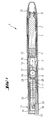
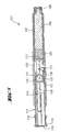
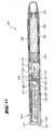
- FIG. 1 there is shown a drug delivery device in accordance with the present invention.
- the drug delivery device (1) comprises a cartridge retaining part (2), and a main (exterior) housing part (3).
- the proximal end of the cartridge retaining part (2) and the distal end of the main housing (3) are secured together by any suitable means known to the person skilled in the art.
- the cartridge retaining part (2) is secured within the distal end of the main housing part (3).
- a cartridge (4) from which a number of doses of a medicinal product may be dispensed is provided in the cartridge retaining part (2).
- a piston (5) is retained in the proximal end of the cartridge (4).
- a removable cap (22) is releasably retained over the distal end of the cartridge retaining part (2).
- the removable cap (22) may be optionally provided with one or more window apertures through which the position of the piston (5) within the cartridge (4) can be viewed.
- the distal end of the cartridge retaining part (2) in the illustrated embodiment is provided with a distal threaded region (6) designed for the attachment of a suitable needle assembly to enable medicament to be dispensed from the cartridge (4).
- the main housing part (3) is provided with an internal housing (7).
- the internal housing (7) is secured against rotational and/or axial movement with respect to the main housing part (3).
- the internal housing (7) is provided with a rack (8) extending along the main axis of the internal housing (7).
- the internal housing (7) may be formed integrally with the main housing part (3).
- the internal housing (7) is provided with a plurality of guide lugs (not shown) and pawl means (not shown).
- the pawl means may be an integrated part of the internal housing (7) or may be a separate component as illustrated.
- a piston rod (10) extending through the main housing (3) has a first set of indentations (not shown) extending longitudinally along external surfaces of the piston rod (10).
- a second set of indentations (11) extend longitudinally along internal surfaces of the piston rod (10).
- the first set of indentations of the piston rod (10) extend through and are engaged with the pawl means of the internal housing (7) to prevent movement of the piston rod (10) in the proximal direction during setting of the device.
- a bearing surface (12) located at the distal end of the piston rod (10) is disposed to abut the proximal face of the piston (5).
- the longitudinal spacing of the first set of indentations and the second set of indentations (11) is essentially equal.
- Pawl arms (29) located on the carrier (28) are releasably engaged with the second set of indentations (11) of the piston rod (10).
- the pawl arms (29) of the carrier (28) are designed to transmit force to the piston rod (10) in the distal direction during dispense and to allow relative movement between the gear (13) and the piston rod (10) in the proximal direction during setting.
- the teeth of the gear wheel (27) are permanently engaged with the teeth of the rack (8) of the internal housing (7).
- a drive member (14) extends about the piston rod (10).
- the drive member (14) comprises a rack part (15) and an activation part (16).
- the rack part (15) and the activation part (16) are secured to each other to prevent rotational and/or axial movement there between.
- the drive member (14) may be a unitary component consisting of an integrated rack part (15) and activation part (16).
- the rack part (15) is provided with a rack (17) extending along the main axis of the rack part (15).
- the teeth of the rack (17) of the rack part (15) are permanently engaged with the teeth of the gear wheel (27).
- the drive member (14) has a plurality of guide slots (not shown) in which the guide lugs (not shown) of the internal housing (7) are located. These guide slots define the extent of permissible axial movement of the drive member (14) with respect to the housing part (3). In the illustrated embodiment the guide slots also prevent rotational movement of the drive member (14) relative to the main housing part (3).
- the activation part (16) of the drive member (14) has a plurality of grip surfaces (18) and a dispensing face (19).
- the main housing part (3) may optionally be provided with a window aperture through which graphical status indicators provided on the drive member (14), can be viewed.
- a user grips the grip surfaces (18) of the drive member (14). The user then pulls the drive member (14) in a proximal direction away from the main housing part (3) thereby moving the rack part (15) in a proximal direction.
- the proximal movement of the rack part (15) causes the gear wheel (27) to rotate and move proximally by virtue of the engagement of the teeth of the gear wheel (27) of the gear (13) with the teeth of the rack (17) of the rack part (15) and the teeth of the rack (8) of the internal housing (7) thus moving the gear (13) in the proximal direction.
- the piston rod (10) is prevented from moving proximally by interaction of pawl means of the internal housing (7) with a first set of indentations on the piston rod (10).
- the pawl arms (29) of the carrier (28) are displaced inwardly by interaction with the second set of indentations (11) of the piston rod (10).
- the proximal travel of the drive member (14) is limited by the guide slots of the rack part (15).
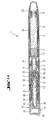
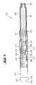
- the pawl arms (29) of the carrier (28) engage with the next sequential indentation of the second set of indentations (11) of the piston rod (10) as indicated in Figure 2 .
- the action of the pawl arms (29) of the carrier (28) positively engaging the second set of indentations (11) of the piston rod (10) creates an audible and tactile feedback to the user to indicate that the dose has been set.
- visual feedback regarding dose setting may optionally be indicated by a graphical status indicator provided on the drive member (14), which can be viewed through an optional window aperture in the main housing part (3).
- the user may then dispense this dose by depressing the dispensing face (19) of the activation part (16) of the drive member (14).
- the drive member (14) and the rack part (15) are moved axially in the distal direction relative to the main housing part (3).
- the gear wheel (27) of the gear (13) is engaged with the teeth of the rack (17) of the rack part (15) and the teeth of the rack (8) of the internal housing (7)
- the gear wheel (27) of the gear (13) is caused to rotate and move in the distal direction thus moving the gear (13) longitudinally in the distal direction.
- the pawl arms (29) of the carrier (28) of the gear (13) are engaged with the second set of indentations (11) of the piston rod (10), the piston rod (10) is caused to move longitudinally in the distal direction with respect to the internal housing (7).
- the distal axial movement of the piston rod (10) causes the bearing surface (12) of the piston rod (10) to bear against the piston (5) of the cartridge (4) causing a dose of medicament to be dispensed through the attached needle (not shown).
- the distal travel of the drive member (14) is limited by the guide slots (not shown) of the rack part (15).
- Audible and tactile feedback to indicate that the dose has been dispensed is provided by the interaction of the pawl means (not shown) of the internal housing (7) with the first set of indentations (not shown) of the piston rod (10).
- visual feedback regarding dose dispensing may optionally be indicated by a graphical status indicator, provided on the drive member (14), which can be viewed through an optional window aperture in the main housing part (3).
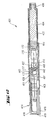
- FIG. 3 shows the drug delivery device of instant invention in a condition where the maximum number of doses has been delivered. In this condition the proximal face (32) of the carrier (28) abuts an internal distal face (33) of the piston rod (10) to prevent further axial movement of the gear (13) and thus the drive member (14) in proximal direction.
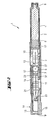
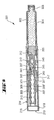
- the drug delivery device (101) comprises a cartridge retaining part (102), and a main (exterior) housing part (103).
- the proximal end of the cartridge retaining part (102) and the distal end of the main housing (103) are secured together by any suitable means known to the person skilled in the art.
- the cartridge retaining part (102) is secured within the distal end of the main housing part (103).
- a cartridge (104) from which a number of doses of a medicinal product may be dispensed is provided in the cartridge retaining part (102).
- a piston (105) is retained in the proximal end of the cartridge (104).
- the distal end of the cartridge retaining part (102) in the illustrated embodiment, is provided with a distal threaded region (106) designed for the attachment of a suitable needle assembly (not shown) to enable medicament to be dispensed from the cartridge (104).
- the main housing part (103) is provided with an internal housing (107).
- the internal housing (107) is secured against rotational and/or axial movement with respect to the main housing part (103).
- the internal housing (107) is provided with a flexible rack (108) extending along the main axis of the internal housing (107).
- the internal housing (107) may be formed integrally with the main housing part (103).
- the internal housing (107) is provided with a plurality of guide slots (not shown) and pawl means (121).
- a piston rod (110) extending through the main housing (103) has a set of teeth (109) extending longitudinally along a surface of the piston rod (110).
- the set of teeth (109) of the piston rod (110) extend through and are engaged with the pawl means (121) of the internal housing (107) to prevent movement of the piston rod (110) in the proximal direction during setting of the device.
- a bearing surface (112) located at the distal end of the piston rod (110) is disposed to abut the proximal face of the piston (105).
- a gear (113) is located within a channel within the piston rod (110).
- An axle (128) of the gear (113) is releasably engaged with the set of teeth (109) of the piston rod (110).
- the set of teeth (109) are designed to allow force transmission to the piston rod (110) in the distal direction during dispense and to allow relative movement between the gear (113) and the piston rod (110) in the proximal direction during setting.
- the teeth of the gear (113) are permanently engaged with the teeth of the flexible rack (108) of the internal housing (107).
- a drive member (114) extends about the piston rod (110).
- the drive member (114) comprises a rack (115) and an activation part (116).
- the rack (115) and the activation part (116) are secured to each other to prevent rotational and/or axial movement there between.
- the drive member (114) may be a unitary component consisting of an integrated rack (115) and activation part (116).
- the teeth of the rack (115) are permanently engaged with the teeth of the gear (113).
- the drive member (114) has a plurality of guide lugs (not shown) which are located in the guide slots (not shown) of the internal housing (107). This defines the extent of permissible axial movement of the drive member (114) with respect to the housing part (103). In the illustrated embodiment the guide slots also prevent rotational movement of the drive member (114) relative to the main housing part (103).
- the activation part (116) of the drive member (114) has a grip surface (118) and a dispensing face (119).
- the main housing part (103) may optionally be provided with a window aperture through which optional graphical status indicators, provided on the drive member (114), can be viewed.
- a user grips the grip surfaces (118) of the drive member (114). The user then pulls the drive member (114) in a proximal direction away from the main housing part (103) thereby moving the rack (115) in a proximal direction.
- the proximal movement of the rack (115) causes the gear (113) to rotate and move proximally by virtue of the engagement of the teeth of the gear (113) with the teeth of rack (115) and the teeth of the flexible rack (108) of the internal housing (107).
- the piston rod (110) is prevented from moving proximally by interaction of pawl means (121) of the internal housing (107) with set of teeth (109) of the piston rod (110).
- the axle (128) of the gear (113) is displaced transversely by interaction with the set of teeth (109) of the piston rod (110) thus deflecting the flexible rack (108) of the internal housing (107).
- the proximal travel of the drive member (114) is limited by the guide slots (not shown) of the internal housing (107).
- the axle (128) of the gear (113) engages with the next sequential tooth of the set of teeth (109) of the piston rod (110) as indicated in Figure 5 .
- the action of the axle (128) of the gear (113) positively engaging the set of teeth (109) of the piston rod (110) under the force provided by the flexible rack (108) of the internal housing (107) creates an audible and tactile feedback to the user to indicate that the dose has been set.
- visual feedback regarding dose setting may optionally be indicated by a graphical status indicator, provided on the drive member (114), which can be viewed through an optional window aperture in the main housing part (103).
- the user may then dispense this dose by depressing the dispensing face (119) of the activation part (116) of the drive member (114).
- the drive member (114) and the rack (115) are moved axially in the distal direction relative to the main housing part (103).
- the gear (113) is rotated and moved in the distal direction.
- the axle (128) of the gear (113) is engaged with the set of teeth (109) of the piston rod (110), thereby causing the piston rod (110) to move longitudinally in the distal direction with respect to the internal housing (107).
- the distal axial movement of the piston rod (110) causes the bearing surface (112) of the piston rod (110) to bear against the piston (105) of the cartridge (104) causing a dose of medicament to be dispensed through the attached needle (not shown).
- the distal travel of the drive member (114) is limited by the guide slots (not shown) of the internal housing (107).
- Audible and tactile feedback to indicate that the dose has been dispensed is provided by the interaction of the pawl means (121) of the internal housing (107) with the set of teeth (109) of the piston rod (110).
- visual feedback regarding dose dispensing may optionally be indicated by a graphical status indicator, provided on the drive member (114), which can be viewed through an optional window aperture in the main housing part (103).
- Further doses may be delivered as required up to a pre-determined maximum number of doses.
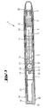
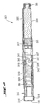
- the drug delivery device (201) comprises a cartridge retaining part (202), and a main (exterior) housing part (203).
- the proximal end of the cartridge retaining part (202) and the distal end of the main housing (203) are secured together by any suitable means known to the person skilled in the art.
- the cartridge retaining part (202) is secured within the distal end of the main housing part (203).
- a cartridge (204) from which a number of doses of a medicinal product may be dispensed is provided in the cartridge retaining part (202).
- a piston (205) is retained in the proximal end of the cartridge (204).
- the distal end of the cartridge retaining part (202) in the illustrated embodiment, is provided with a distal threaded region (206) designed for the attachment of a suitable needle assembly to enable medicament to be dispensed from the cartridge (204).
- the main housing part (203) is provided with an internal housing (207).
- the internal housing (207) is secured against rotational and/or axial movement with respect to the main housing part (203).
- the internal housing (207) is provided with a fixing point (208) for attaching a pulley (240).
- the internal housing (207) may be formed integrally with the main housing part (203).
- the internal housing (207) is provided with a guide slot (not shown) and pawl means (not shown).
- a piston rod (210) extending through the main housing (203) has a first set of teeth (209) and a second set of teeth (211) extending longitudinally along surfaces of the piston rod (210).
- the second set of teeth (211) of the piston rod (210) extends through and is engaged with the pawl means (not shown) of the internal housing (207) to prevent movement of the piston rod (210) in the proximal direction during setting of the device.
- a bearing surface (212) located at the distal end of the piston rod (210) is disposed to abut the proximal face of the piston (205).
- a pulley (240), comprising a belt (241) and a wheel (242) is located within a channel within the piston rod (210).
- An axle (228) of the wheel (242) is releasably engaged with the first set of teeth (209) of the piston rod (210).
- the first set of teeth (209) are designed to allow force transmission to the piston rod (210) in the distal direction during dispense and to allow relative movement between the pulley (240) and the piston rod (210) in the proximal direction during setting.
- the teeth of the wheel (242) are permanently engaged with the teeth of the belt (241) of pulley (240).
- a drive member (214) extends about the piston rod (210).
- the drive member (214) comprises a fixing point (215) and an activation part (216).
- the fixing point (215) and the activation part (216) are secured to each other to prevent rotational and/or axial movement there between.
- the drive member (214) may be a unitary component consisting of an integrated fixing point (215) and activation part (216).
- the belt (241) of the pulley (240) is attached to the drive member (214) at the fixing point (215).
- the drive member (214) has a guide lug (not shown) which is located in the guide slot (not shown) of the internal housing (207). This defines the extent of permissible axial movement of the drive member (214) with respect to the housing part (203). In the illustrated embodiment the guide slot also prevents rotational movement of the drive member (214) relative to the main housing part (203).
- the activation part (216) of the drive member (214) has a grip surface (218) and a dispensing face (219).
- the main housing part (203) may be provided with an optional window aperture through which optional graphical status indicators, provided on the drive member (214), can be viewed.
- a user grips the grip surfaces (218) of the drive member (214). The user then pulls the drive member (214) in a proximal direction away from the main housing part (203) thereby moving the fixing point (215) in a proximal direction.
- the proximal movement of the drive member (214) causes the wheel (242) of the pulley (240) to rotate and move proximally by virtue of the attachment of the belt (241) of the pulley (240) to both the fixing point (215) of the drive member (214) and the fixing point (208) of the internal housing (207).
- the piston rod (210) is prevented from moving proximally by the interaction of pawl means (not shown) of the internal housing (207) with the second set of teeth (211) of the piston rod (210).
- the axle (228) of the wheel (242) is displaced transversely by interaction with the first set of teeth (209) of the piston rod (210) thus deflecting the belt (241) of the pulley (240).
- the proximal travel of the drive member (214) is limited by the guide slot (not shown) of the internal housing (207).
- the axle (228) of the wheel (242) engages with the next sequential tooth of the first set of teeth (209) of the piston rod (210) as indicated in Figure 7 .
- the action of the axle (228) of the wheel (242) positively engaging the first set of teeth (209) of the piston rod (210) under the force provided by the belt (241) of the pulley (240) creates an audible and tactile feedback to the user to indicate that the dose has been set.
- visual feedback regarding dose setting may optionally be indicated by a graphical status indicator, provided on the drive member (214), which can be viewed through an optional window aperture in the main housing part (203).
- the user may then dispense this dose by depressing the dispensing face (219) of the activation part (216) of the drive member (214).
- the drive member (214) and the fixing point (215) are moved axially in the distal direction relative to the main housing part (203).
- the belt (241) of the pulley (240) is attached to the fixing point (215) of the drive member (214) and the belt (241) of the pulley (240) is also attached to the fixing point (208) of the internal housing (207) the wheel (242) of the pulley (240) is rotated and moved in the distal direction by the engagement of the teeth of the belt (241) with the teeth of the wheel (242).
- the axle (228) of the wheel (242) of the pulley (240) is engaged with the first set of teeth (209) of the piston rod (210), thereby causing the piston rod (210) to move axially in the distal direction with respect to the internal housing (207).
- the distal axial movement of the piston rod (210) causes the bearing surface (212) of the piston rod (210) to bear against the piston (205) of the cartridge (204) causing a dose of medicament to be dispensed through the attached needle (not shown).
- the distal travel of the drive member (214) is limited by the guide slot (not shown) of the internal housing (207).
- Audible and tactile feedback to indicate that the dose has been dispensed is provided by the interaction of the pawl means (not shown) of the internal housing (207) with the second set of teeth (211) of the piston rod (210).
- visual feedback regarding dose dispensing may optionally be indicated by a graphical status indicator, provided on the drive member (214), which can be viewed through an optional window aperture in the main housing part (203).
- Further doses may be delivered as required up to a pre-determined maximum number of doses.
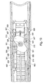
- the drug delivery device (301) comprises a cartridge retaining part (302), and a main (exterior) housing part (303).
- the proximal end of the cartridge retaining part (302) and the distal end of the main housing (303) are secured together by any suitable means known to the person skilled in the art.
- the cartridge retaining part (302) is secured within the distal end of the main housing part (303).
- a cartridge (304) from which a number of doses of a medicinal product may be dispensed is provided in the cartridge retaining part (302).
- a piston (305) is retained in the proximal end of the cartridge (304).
- the distal end of the cartridge retaining part (302) in the illustrated embodiment, is provided with a distal threaded region (306) designed for the attachment of a suitable needle assembly (not shown) to enable medicament to be dispensed from the cartridge (304).
- the main housing part (303) is provided with an internal housing (307).
- the internal housing (307) is secured against rotational and/or axial movement with respect to the main housing part (303).
- the internal housing (307) is provided with a fulcrum point (308) for attaching a lever (340).
- the internal housing (307) may be formed integrally with the main housing part (303).
- the internal housing (307) is provided with a guide slots (not shown) and pawl means (345).
- a piston rod (310) extending through the main housing (303) has a first set of indentations (309 and 309') and a second set of indentations (311 and 311') extending longitudinally along surfaces of the piston rod (310).
- the second set of indentations (311 and 311') of the piston rod (310) extends through and is engaged with the pawl means (345) of the internal housing (307) to prevent movement of the piston rod (310) in the proximal direction during setting of the device.
- a bearing surface (312) located at the distal end of the piston rod (310) is disposed to abut the proximal face of the piston (305).
- the lugs (341) of the lever (340) are releasably engaged with the first set of indentations (309 and 309') of the piston rod (310).
- the first set of indentations (309 and 309') are designed to allow force transmission to the piston rod (310) in the distal direction during dispense and to allow relative movement between the lever (340) and the piston rod (310) in the proximal direction during setting.
- the first pivot (342) of the lever (340) is attached to the fulcrum (308) of the internal housing (307) for pivotable movement there between.
- a drive member (314) extends about the piston rod (310).
- the drive member (314) comprises a slot (315) and an activation part (316).
- the slot (315) and the activation part (316) are secured to each other to prevent rotational and/or axial movement there between.
- the drive member (314) may be a unitary component consisting of an integrated slot (315) and activation part (316).
- the second pivot (343) of the lever (340) is located within the slot (315) of the drive member (314).
- the slot (315) of the drive member (314) is designed to allow transverse movement, but not longitudinal movement, of the second pivot (343) of the lever (340) relative to the drive member (314).
- the drive member (314) has guide lugs (346) which are located in the guide slots (not shown) of the internal housing (307). This defines the extent of permissible axial movement of the drive member (314) with respect to the housing part (303). In the illustrated embodiment the guide slots also prevent rotational movement of the drive member (314) relative to the main housing part (303).
- the activation part (316) of the drive member (314) has a grip surface (318) and a dispensing face (319).
- the main housing part (303) may be provided with an optional window aperture through which optional graphical status indicators, provided on the drive member (314), can be viewed.
- a user grips the grip surfaces (318) of the drive member (314). The user then pulls the drive member (314) in a proximal direction away from the main housing part (303) thereby moving the fixing point (315) in a proximal direction.
- the proximal movement of the drive member (314) causes the lever (340) to rotate about the fulcrum (308) of the internal housing (307) in a proximal direction by virtue of the location of the second pivot (343) of the lever (340) within the slot (315) of the drive member (314).
- the piston rod (310) is prevented from moving proximally by interaction of pawl means (345) of the internal housing (307) with the second set of indentations (311 and 311') of the piston rod (310).
- the lugs (341) of the lever (340) are displaced transversely by interaction with the first set of indentations (309 and 309') of the piston rod (310).
- the proximal travel of the drive member (314) is limited by the guide slots (not shown) of the internal housing (307).
- the lugs (341) of the lever (340) engage with the next sequential indentation of the first set of indentations (309 and 309') of the piston rod (310) as indicated in Figure 10 .
- the action of the lugs (341) of the lever (340) positively engaging the first set of indentations (309 and 309') of the piston rod (310) under a force provided by the transverse deflection of the lever (340) creates an audible and tactile feedback to the user to indicate that the dose has been set.
- visual feedback regarding dose setting may optionally be indicated by a graphical status indicator, provided on the drive member (314), which can be viewed through an optional window aperture in the main housing part (303).
- the user may then dispense this dose by depressing the dispensing face (319) of the activation part (316) of the drive member (314).
- the drive member (314) and the slot (315) are moved axially in the distal direction relative to the main housing part (303).
- the lever (340) is rotated about the fulcrum (308) of the internal housing (307) in the distal direction.
- the lugs (341) of the lever (340) are engaged with the first set of indentations (309 and 309') of the piston rod (310), thereby causing the piston rod (310) to move axially in the distal direction with respect to the internal housing (307).
- the distal axial movement of the piston rod (310) causes the bearing surface (312) of the piston rod (310) to bear against the piston (305) of the cartridge (304) causing a dose of medicament to be dispensed through the attached needle (not shown).
- the distal travel of the drive member (314) is limited by the guide slots (not shown) of the internal housing (307).
- Audible and tactile feedback to indicate that the dose has been dispensed is provided by the interaction of the pawl means (345) of the internal housing (307) with the second set of indentations (311 and 311') of the piston rod (310).
- visual feedback regarding dose dispensing may optionally be indicated by a graphical status indicator, provided on the drive member (314), which can be viewed through an optional window aperture in the main housing part (303).
- Further doses may be delivered as required up to a pre-determined maximum number of doses.
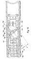
- the drug delivery device (401) comprises a cartridge retaining part (402), and a main (exterior) housing part (403).
- the proximal end of the cartridge retaining part (402) and the distal end of the main housing (403) are secured together by any suitable means known to the person skilled in the art.
- the cartridge retaining part (402) is secured within the distal end of the main housing part (403).
- a cartridge (404) from which a number of doses of a medicinal product may be dispensed is provided in the cartridge retaining part (402).
- a piston (405) is retained in the proximal end of the cartridge (404).
- a removable cap (422) is releasably retained over the distal end of the cartridge retaining part (402).
- the removable cap (422) is optionally provided with one or more window apertures through which the position of the piston (405) within the cartridge (404) can be viewed.
- the distal end of the cartridge retaining part (402) in the illustrated embodiment, is provided with a distal threaded region (406) designed for the attachment of a suitable needle assembly (not shown) to enable medicament to be dispensed from the cartridge (404).
- the main housing part (403) is provided with an internal housing (407).
- the internal housing (407) is secured against rotational and/or axial movement with respect to the main housing part (403).
- the internal housing (407) is provided with a fulcrum (408).
- the internal housing (407) may be formed integrally with the main housing part (403).
- the internal housing (407) is provided with a plurality of guide lugs (not shown) and pawl means (not shown).
- the pawl means may be an integrated part of the internal housing (407) or may be a separate component as illustrated.
- a piston rod (410) extending through the main housing (403) has a first set of indentations (not shown) extending longitudinally along external surfaces of the piston rod (410).
- a second set of indentations (411) extend longitudinally along internal surfaces of the piston rod (410).
- the first set of indentations of the piston rod (410) extend through and are engaged with the pawl means of the internal housing (407) to prevent movement of the piston rod (410) in the proximal direction during setting of the device.
- a bearing surface (412) located at the distal end of the piston rod (410) is disposed to abut the proximal face of the piston (405).
- the longitudinal spacing of the first set of indentations and the second set of indentations (411) is essentially equal.
- the lever (427) is provided with a first pivot (442) and a second pivot (443).
- Pawl arms (429) located on the carrier (428) are releasably engaged with the second set of indentations (411) of the piston rod (410).
- the pawl arms (429) of the carrier (428) are designed to transmit force to the piston rod (410) in the distal direction during dispense and to allow relative movement between the lever assembly (413) and the piston rod (410) in the proximal direction during setting.
- the first pivot (442) of the lever (427) is attached to the fulcrum (408) of the internal housing (407) for pivotable movement there between.
- a drive member (414) extends about the piston rod (410).
- the drive member (414) comprises a slotted part (415) and an activation part (416).
- the slotted part (415) and the activation part (416) are secured to each other to prevent rotational and/or axial movement there between.
- the drive member (414) may be a unitary component consisting of an integrated slotted part (415) and activation part (416).
- the slotted part (415) is provided with a slot (417) that is essentially perpendicular to the main axis of the drive member (414).
- the second pivot (443) of the lever (427) is located within the slot (417) of the internal housing (407).
- the slot (415) of the drive member (414) is designed to allow transverse movement, but not longitudinal movement, of the second pivot (443) of the lever (427) relative to the drive member (414).
- the drive member (414) has a plurality of guide slots (not shown) in which the guide lugs (not shown) of the internal housing (407) are located. These guide slots define the extent of permissible axial movement of the drive member (414) with respect to the housing part (403). In the illustrated embodiment the guide slots also prevent rotational movement of the drive member (414) relative to the main housing part (403).
- the activation part (416) of the drive member (414) has a plurality of grip surfaces (418) and a dispensing face (419).
- the main housing part (403) may be provided with an optional window aperture through which optional graphical status indicators, provided on the drive member (414), can be viewed.
- a user grips the grip surfaces (418) of the drive member (414). The user then pulls the drive member (414) in a proximal direction away from the main housing part (403) thereby moving the slotted part (415) in a proximal direction.
- the proximal movement of the drive member (414) causes the lever (427) to rotate about the fulcrum (408) of the internal housing (407) in a proximal direction by virtue of the location of the second pivot (443) of the lever (427) within the slot (417) of the drive member (414).
- the piston rod (410) is prevented from moving proximally by interaction of pawl means (not shown) of the internal housing (407) with the first set of indentations (not shown) of the piston rod (410).
- the pawl arms (429) of the carrier (428) are displaced inwardly by interaction with the second set of indentations (411) of the piston rod (410).
- the proximal travel of the drive member (414) is limited by the guide slots (not shown) of the slotted part (415).
- the pawl arms (429) of the carrier (428) engage with the next sequential indentation of the second set of indentations (411) of the piston rod (410) as indicated in Figure 12 .
- the action of the pawl arms (429) of the carrier (428) positively engaging the second set of indentations (411) of the piston rod (410) creates an audible and tactile feedback to the user to indicate that the dose has been set.
- visual feedback regarding dose setting may optionally be indicated by a graphical status indicator, provided on the drive member (414), which can be viewed through an optional window aperture in the main housing part (403).
- the user may then dispense this dose by depressing the dispensing face (419) of the activation part (416) of the drive member (414).
- the drive member (414) and the slotted part (415) are moved axially in the distal direction relative to the main housing part (403).
- the lever (427) is rotated about the fulcrum (408) of the internal housing (407) in the distal direction.
- the piston rod (410) is caused to move longitudinally in the distal direction with respect to the internal housing (407).
- the distal axial movement of the piston rod (410) causes the bearing surface (412) of the piston rod (410) to bear against the piston (405) of the cartridge (404) causing a dose of medicament to be dispensed through the attached needle.
- the distal travel of the drive member (414) is limited by the guide slots (not shown) of the slotted part (415).
- Audible and tactile feedback to indicate that the dose has been dispensed is provided by the interaction of the pawl means (not shown) of the internal housing (407) with the first set of indentations (not shown) of the piston rod (410).
- visual feedback regarding dose dispensing may optionally be indicated by a graphical status indicator, provided on the drive member (414), which can be viewed through an optional window aperture in the main housing part (403).
- Further doses may be delivered as required up to a pre-determined maximum number of doses.
- the examples 6A to 6C refer to alternative embodiments of drive mechanisms according to the present invention comprising a rotating means which is a lever assembly.
- the lever assembly 513 works essentially similarly to the lever assembly which has been described with reference to figures 11 and 12 . It comprises a carrier 528 and a lever 527 which is designed to rotate with respect to the carrier 528 around a rotational axis 555.
- the carrier 528 is located within a channel within a piston rod 510.
- the lever 527 is provided with a first pivot 542 and a second pivot 543.
- Pawl arms 529 located on the carrier 528 are releasably engaged with a second set of indentations 511 which extend longitudinally along internal surfaces of the piston rod 510.
- the pawl arms 529 of the carrier 528 are designed to transmit force to the piston rod 510 in the distal direction during dispense and to allow a movement of the lever assembly 513 with respect to the piston rod 510 in the proximal direction during dose setting.
- the first pivot 542 of the lever 527 is located within a slot 508 of an internal housing 507 for pivotable movement there between.
- the second pivot 543 of the lever 527 is located within another slot 517 of a slotted part 515 of a drive member 514, the drive member 514 moving axially with respect to a main housing part 503 during dose setting and dose delivery.
- the lever 527 has an essentially mirror-symmetrical form. It comprises two opposing flat sides 551 which lie essentially parallel with the longitudinal axis of the drug delivery device before a dose to be dispensed is set and two further opposing flat sides 550 which lie essentially parallel with the longitudinal axis of the drug delivery device when the dose has been set and before it is dispensed.
- This design of the lever 527 has the advantage of aiding the initial assembly of the drive mechanism.
- the (except for the flat sides 550 and 551) nearly round form of the lever 527 which provides an area of contact with the internal surfaces of the drive member 514 and the internal housing 507, thereby providing guidance for the axial movement of the carrier 528.
- the lever assembly 613 works essentially similarly to the lever assemblies which have been described with reference to figures 11 to 13 . It comprises a carrier 628 and a lever 627 which is designed to rotate with respect to the carrier 628 around a rotational axis 655.
- the carrier 628 is located within a channel within a piston rod 610.
- the lever 627 is provided with a first pivot 642 and a second pivot 643.
- Pawl arms 629 located on the carrier 628 are releasably engaged with a second set of indentations 611 which extend longitudinally along internal surfaces of the piston rod 610.
- the pawl arms 629 of the carrier 628 are designed to transmit force to the piston rod 610 in the distal direction during dispense and to allow a movement of the lever assembly 613 with respect to the piston rod 610 in the proximal direction during dose setting.
- the first pivot 642 of the lever 627 is located within a slot 608 of an internal housing 607 for pivotable movement there between.
- the second pivot 643 of the lever 627 is located within a slot 617 of a slotted part 615 of a drive member 614, the drive member 614 moving axially with respect to a main housing part 603 during dose setting and dose delivery.
- this lever assembly 613 is designed to have a mechanical advantage different to the 2:1 advantage e.g. of a gear assembly.
- the mechanical advantage of the shown lever assembly 613 is equal to (X+Y) divided by X.
- the lever assembly 713 works essentially similarly to the lever assemblies which have been described with reference to figures 11 to 14 . It comprises a carrier 728 and a lever 727 which is designed to rotate with respect to the carrier 728 around a rotational axis 755.
- the carrier 728 is located within a channel within a piston rod 710.
- the lever 727 is provided with a first pivot 742 and a second pivot 743.
- Pawl arms 729 located on the carrier 728 are releasably engaged with a second set of indentations 711 which extend longitudinally along internal surfaces of the piston rod 710.
- the pawl arms 729 of the carrier 728 are designed to transmit force to the piston rod 710 in the distal direction during dispense and to allow a movement of the lever assembly 713 with respect to the piston rod 710 in the proximal direction during dose setting.
- the first pivot 742 of the lever 727 is located in a slot 708 of an internal housing 707 for pivotable movement there between.
- the second pivot 743 of the lever 727 is located within a slot 717 of a slotted part 715 of a drive member 714, the drive member 714 moving axially with respect to a main housing part 703 during dose setting and dose delivery.
- this lever assembly 713 is designed to have a mechanical advantage different to the 2:1 advantage e.g. of a gear assembly.
- the mechanical advantage of the shown lever assembly 713 is equal to (X+Y) divided by X.
- the lever 727 has a symmetrical design such that it carries features which can be used as first and second pivots 742, 743 on both sides, even though the drive mechanism only makes use of one of these features on each side.
- the fulcrum 708 of the internal housing 707 interacts with a first pivot 742 which is a feature located at the distance X from the rotational axis 755 of the lever 727 on one side.
- the slotted part 715 of the drive member 714 interacts with a second pivot 743 which is a feature located at the distance Y from the rotational axis 755 of the lever 727 on the other side.
- the two remaining features 760 are not used in the assembled drive mechanism.
- This symmetrical design has the advantage of reducing the costs and the complexity of assembling the drive mechanism because the feeding of the lever to an assembly line in the correct orientation is simplified.
Abstract
a housing;
a drive member located within the housing such that the drive member is movable longitudinally and is non-rotatable with respect to the housing;
a piston rod that is non-rotatable with respect to the housing and is adapted to operate through the housing and transfer a force in the longitudinal direction to the distal end of the drug delivery device;
a rotating means releasably engaged with the piston rod and engaged to the drive member and engaged to the housing.
When the said drive member moves proximally with respect to the said housing the said rotating means moves proximally with respect to the said piston rod; and
when the said drive member moves distally the rotating means moves distally displacing the piston rod towards the distal end of the device.
Description
- The present invention relates to drive mechanisms suitable for use in drug delivery devices, in particular pen-type injectors, wherein a number of pre-set doses of medicinal product can be administered. In particular, the present invention relates to such drug delivery devices where a user may activate the drug delivery device.
- Such drug delivery devices have application where persons without formal medical training, i.e., patients, need to administer an accurate and predefined dose of a medicinal product, such as heparin or insulin. In particular, such devices have application where medicinal product is administered on an irregular basis over a short-term or long-term period.
- These circumstances set a number of requirements for drug delivery devices of this kind. The device must be robust in construction, yet easy to use in terms of the manipulation of the parts, understanding by a user of its operation and the delivery of the required dose of medicament. Dose setting must be easy and unambiguous. Where the device is to be disposable rather than reusable, the device should be cheap to manufacture and easy to dispose of (preferably being suitable for recycling). To meet these requirements the number of parts required to assemble the device and the number of material types the device is made from need to be kept to a minimum.
- User operated drug delivery devices are well known within the medical field.
-
WO 9626754 A2 - An injection device is disclosed in
WO 01/95959 A1 -
US 5,782,633 teaches an applicator for a dental compound having an elongated implement body and a gearwheel/pinion pair connected to two moving racks, one rack located on a pusher rod and another rack located on a ram. - In
WO 03/080160 A1 - Surprisingly it was found that the drive mechanism according to instant invention without having two pinions provides a valuable technical alternative for push-pull drive mechanisms, wherein reduced force is needed to actuate the mechanism. This is achieved by the introduction of a piston rod and rotating means as defined by instant invention. Further the drive mechanism according to instant invention further provides the advantage of intuitive and easy to use dose setting.
- According to a first aspect of the present invention, a drive mechanism for use in a drug delivery device is provided comprising:
- a housing having a proximal and a distal end;
- a drive member located within the said housing such that the said drive member is movable longitudinally;
- a piston rod adapted to operate through the housing and transfer a force in the longitudinal direction to the distal end of the drug delivery device;
- a rotating means releasably engaged with the said piston rod and engaged to the said drive member and engaged to the said housing;
- characterized in that,
- a) when the said drive member moves proximally with respect to the said housing the said rotating means moves proximally with respect to the said piston rod;
- b) when the said drive member moves distally the said rotating means moves distally displacing the said piston rod towards the distal end of the device.
- In a preferred embodiment of the drive mechanism of instant invention the said drive member is non-rotatable with respect to the said housing.
- In another preferred embodiment of the drive mechanism of instant invention the said piston rod is non-rotatable with respect to the said housing.
- In a further preferred embodiment of the drive mechanism of instant invention the rotating means is a gear.
- In yet a further preferred embodiment of the drive mechanism of instant invention the gear is free to translate relative to the said piston rod.
- In another further preferred embodiment of the drive mechanism of instant invention the engagement between the piston rod and the gear acts through the axle of the said gear.
- In yet another further preferred embodiment of the drive mechanism of instant invention the gear is designed to be engaged with a rack located on the drive member and a rack located on the housing.
- In a further embodiment of the drive mechanism of instant invention the rotating means is a lever.
- In yet another embodiment of the drive mechanism of instant invention the rotating means is a pulley.
- In yet a further embodiment of the drive mechanism of instant invention the rotating means is a lever assembly.
- The invention further relates to a drive mechanism for a drug delivery device with a lever assembly which comprises a lever which is designed to pivot with respect to a carrier around a rotational axis. The carrier is movable in a proximal direction with respect to the piston rod. The lever is provided with a first pivot and a second pivot. The first pivot interacts with the housing and the second pivot interacts with the drive member such that the lever is pivoted when the drive member is moved axially with respect to the housing. The distance Y between the rotational axis of the lever and the second pivot is different than the distance X between the rotational axis of the lever and the first pivot which results in a mechanical advantage different than 2:1..
- The term "drug delivery device" according to instant invention shall mean a single-dose or multi-dose or pre-set dose or pre-defined, disposable or re-useable device designed to dispense a user selectable or pre-defined dose of a medicinal product, preferably multiple pre-defined doses, e.g. insulin, growth hormones, low molecular weight heparins, and their analogues and/or derivatives etc. Said device may be of any shape, e.g. compact or pen-type. Dose delivery may be provided through a mechanical (optionally manual) or electrical drive mechanism or stored energy mechanism, such as a spring, etc. Dose selection may be provided through a manual mechanism or electronic mechanism. Additionally, said device may contain components designed to monitor physiological properties such as blood glucose levels, etc. Furthermore, the said device may comprise a needle or may be needle-free. In particular, the term "drug delivery device" shall mean a disposable needle-based pen-type device providing multiple pre-defined doses having mechanical and manual dose delivery and dose selection mechanisms, which is designed for use by persons without formal medical training such as patients. Preferably, the drug delivery device is of the injector-type.
- The term "housing" according to instant invention shall preferably mean any exterior housing ("main housing", "body", "shell") or interior housing ("insert", "inner body") having a unidirectional axial coupling to prevent proximal movement of specific components. The housing may be designed to enable the safe, correct, and comfortable handling of the drug delivery device or any of its mechanism. Usually, it is designed to house, fix, protect, guide, and/or engage with any of the inner components of the drug delivery device (e.g., the drive mechanism, cartridge, plunger, piston rod) by limiting the exposure to contaminants, such as liquid, dust, dirt etc. In general, the housing may be unitary or a multipart component of tubular or non-tubular shape. Usually, the exterior housing serves to house a cartridge from which a number of doses of a medicinal product may by dispensed.
In a more specific embodiment of instant invention, the exterior housing is provided with a plurality of maximum dose stops adapted to be abutted by an axial stop provided on the drive member. - The term "engaged" according to instant invention shall particularly mean the interlocking of two or more components of the drive mechanism/drug delivery device, e.g. a spline, thread, or meshed teeth connection, preferably the interlocking of meshed teeth of components.
- The term "drive member" according to instant invention shall mean any component adapted to operate through/within the housing, designed to translate axial movement through/within the drug delivery device, preferably from an actuation means to the piston rod. In a preferred embodiment the drive member is further releasably engaged with the piston rod. The drive member may be of unitary or multipart construction.
- The term "releasably engaged" according to instant invention shall preferably mean that two components of instant mechanism or device are joined for translation of force or movement in one direction only, preferably during dispense.
- The term "piston rod" according to instant invention shall mean a component adapted to operate through/within the housing, designed to translate axial movement through/within the drug delivery device, preferably from the drive member to the piston, for the purpose of discharging/dispensing an injectable product. Said piston rod may be flexible or not. It may be a simple rod, a lead-screw, a rack and pinion system, a worm gear system, or the like. The "piston rod" shall further mean a component having a circular or non-circular cross-section. It may be made of any suitable material known by a person skilled in the art and may be of unitary or multipart construction. In a preferred embodiment, the piston rod comprises a series of one or more sets of longitudinally spaced ribs and/or indentations.
- The term "rotating means" according to instant invention shall mean any rotating component that transfers force and/or movement from the drive member to the piston rod. It may be made of any suitable material known by a person skilled in the art and may be of unitary or multipart construction. In a preferred embodiment the rotating means may be a gear component, more preferably a spur gear. In another preferred embodiment the rotating means may be a lever. In yet another preferred embodiment the rotating means may be a pulley. In yet a further preferred embodiment the rotating means may be a lever assembly.
- The term "gear" according to instant invention shall mean a toothed wheel used in conjunction with a rack and/or another gear, preferably a rack, to transmit force and/or motion. In a preferred embodiment the gear may be a spur gear. In yet another preferred embodiment the term "gear" means a gear wheel mounted within a carrier.
- The term "lever" according to instant invention shall mean any beam component pivoted about a fulcrum to transmit force and/or motion. In a preferred embodiment the fulcrum point is located on the housing and load is applied through the drive member. In yet another preferred embodiment the term "lever" shall mean any beam component that moves essentially proximally with respect to the piston rod during dose setting and that moves essentially distally with respect to the piston rod during dose delivery.
- The term "pulley" according to instant invention shall mean any wheel and/or belt component that is designed to transmit force and/or motion. In a preferred embodiment the pulley comprises a wheel and belt. In a more preferred embodiment the belt of the pulley is attached to the housing and the drive member and the wheel of the pulley engages with the piston rod and the belt of the pulley. In yet another preferred embodiment the wheel of the pulley is releasably engaged with the piston rod.
- The term "lever assembly" according to instant invention shall mean any component consisting of a lever and a carrier designed to transmit force and/or motion.
- The term "rack" according to instant invention shall mean any component having a linear array of ribs and/or indentations and/or gear-form teeth. In a preferred embodiment a rack is located in the housing and a further rack is located in the drive member. In a further preferred embodiment one and/or both, more preferably one, of the racks located on the housing or on the drive member is flexible and/or pivoted and/or movable in one or more axis, more preferably one.
- The term "graphical status indicator" according to instant invention shall preferably mean any markings, symbols, numerals, etc., e.g. printed on the external surface of a component of the device, for example the drive sleeve or an odometer or a dose dial sleeve, or the like, preferably the drive sleeve, for indicating to the user when the device has been activated and/or is in operation and/or direction of operation and/or a dose of medicament has been delivered.
- The "distal end" of the device or a component of the device shall mean the end, which is closest to the dispensing end of the device.
- The "proximal end" of the device or a component of the device shall mean the end, which is furthest away from the dispensing end of the device.
- A second aspect of instant invention provides an assembly for use in a drug delivery device comprising the drive mechanism according to instant invention.
- A third aspect of the present invention provides a drug delivery device comprising the drive mechanism or the assembly according to instant invention.
- A fourth aspect of the present invention provides a method of assembling a drug delivery device comprising the step of providing a drive mechanism or an assembly according to instant invention.
- A fifth aspect of instant invention is the use of a drug delivery device according to instant invention for dispensing a medicinal product preferably dispensing a pharmaceutical formulation (e.g. solution, suspension etc.) comprising an active compound selected from the group consisting of insulin, growth hormone, low molecular weight heparin, their analogues and their derivatives.
- Without any limitation, the instant invention will be explained in greater detail below in connection with a preferred embodiment and with reference to the drawings in which:
-
Figure 1 shows a sectional view of a first embodiment of the drug delivery device in accordance with the present invention in a first, cartridge full, position; -
Figure 1A shows a further sectional view of a first embodiment of the drug delivery device in accordance with the present invention in a first, cartridge full, position; -
Figure 2 shows a sectional view of a first embodiment of the drug delivery device in accordance with the present invention in a second, first dose set, position; -
Figure 3 shows a sectional view of a first embodiment of the drug delivery device in accordance with the present invention in a third, final dose dispensed, position; -
Figure 4 shows a sectional view of a second embodiment of the drug delivery device in accordance with the present invention in a first, cartridge full, position; -
Figure 5 shows a sectional view of a second embodiment of the drug delivery device in accordance with the present invention in a second, first dose set, position; -
Figure 6 shows a sectional view of a third embodiment of the drug delivery device in accordance with the present invention in a first, cartridge full, position; -
Figure 7 shows a sectional view of a third embodiment of the drug delivery device in accordance with the present invention in a second, first dose set, position; -
Figure 8 shows a sectional view of a fourth embodiment of the drug delivery device in accordance with the present invention in a first, cartridge full, position; -
Figure 9 shows a further sectional view of a fourth embodiment of the drug delivery device in accordance with the present invention in a first, cartridge full, position; -
Figure 10 shows a sectional view of a fourth embodiment of the drug delivery device in accordance with the present invention in a second, first dose set, position. -
Figure 11 shows a sectional view of a fifth embodiment of the drug delivery device in accordance with the present invention in a first, cartridge full, position; -
Figure 12 shows a sectional view of a fifth embodiment of the drug delivery device in accordance with the present invention in a second, first dose set, position. -
Figures 13 to 15 show a sectional view of three further embodiments of a drive mechanism for a drug delivery device according to the present invention comprising a lever assembly. - Referring first to
Figures 1 to 3 , there is shown a drug delivery device in accordance with the present invention. - The drug delivery device (1) comprises a cartridge retaining part (2), and a main (exterior) housing part (3). The proximal end of the cartridge retaining part (2) and the distal end of the main housing (3) are secured together by any suitable means known to the person skilled in the art. In the illustrated embodiment, the cartridge retaining part (2) is secured within the distal end of the main housing part (3).
- A cartridge (4) from which a number of doses of a medicinal product may be dispensed is provided in the cartridge retaining part (2). A piston (5) is retained in the proximal end of the cartridge (4).
- A removable cap (22) is releasably retained over the distal end of the cartridge retaining part (2). The removable cap (22) may be optionally provided with one or more window apertures through which the position of the piston (5) within the cartridge (4) can be viewed.
- The distal end of the cartridge retaining part (2) in the illustrated embodiment, is provided with a distal threaded region (6) designed for the attachment of a suitable needle assembly to enable medicament to be dispensed from the cartridge (4).
- In the illustrated embodiment, the main housing part (3) is provided with an internal housing (7). The internal housing (7) is secured against rotational and/or axial movement with respect to the main housing part (3). The internal housing (7) is provided with a rack (8) extending along the main axis of the internal housing (7). Alternatively, the internal housing (7) may be formed integrally with the main housing part (3). Additionally, the internal housing (7) is provided with a plurality of guide lugs (not shown) and pawl means (not shown). The pawl means may be an integrated part of the internal housing (7) or may be a separate component as illustrated.
- A piston rod (10) extending through the main housing (3) has a first set of indentations (not shown) extending longitudinally along external surfaces of the piston rod (10). A second set of indentations (11) extend longitudinally along internal surfaces of the piston rod (10). The first set of indentations of the piston rod (10) extend through and are engaged with the pawl means of the internal housing (7) to prevent movement of the piston rod (10) in the proximal direction during setting of the device. A bearing surface (12) located at the distal end of the piston rod (10) is disposed to abut the proximal face of the piston (5). In the illustrated embodiment the longitudinal spacing of the first set of indentations and the second set of indentations (11) is essentially equal.
- A gear (13), consisting of a carrier (28) and a gear wheel (27), free to rotate within the carrier (28), is located within a channel within the piston rod (10). Pawl arms (29) located on the carrier (28) are releasably engaged with the second set of indentations (11) of the piston rod (10). The pawl arms (29) of the carrier (28) are designed to transmit force to the piston rod (10) in the distal direction during dispense and to allow relative movement between the gear (13) and the piston rod (10) in the proximal direction during setting. The teeth of the gear wheel (27) are permanently engaged with the teeth of the rack (8) of the internal housing (7).
- A drive member (14) extends about the piston rod (10). The drive member (14) comprises a rack part (15) and an activation part (16). The rack part (15) and the activation part (16) are secured to each other to prevent rotational and/or axial movement there between. Alternatively, the drive member (14) may be a unitary component consisting of an integrated rack part (15) and activation part (16).
- The rack part (15) is provided with a rack (17) extending along the main axis of the rack part (15). The teeth of the rack (17) of the rack part (15) are permanently engaged with the teeth of the gear wheel (27).
- The drive member (14) has a plurality of guide slots (not shown) in which the guide lugs (not shown) of the internal housing (7) are located. These guide slots define the extent of permissible axial movement of the drive member (14) with respect to the housing part (3). In the illustrated embodiment the guide slots also prevent rotational movement of the drive member (14) relative to the main housing part (3).
- The activation part (16) of the drive member (14) has a plurality of grip surfaces (18) and a dispensing face (19).
- To increase intuitiveness of the operation of the device, the main housing part (3) may optionally be provided with a window aperture through which graphical status indicators provided on the drive member (14), can be viewed.
- Operation of the drug delivery device in accordance with the present invention will now be described.
- To set a dose a user grips the grip surfaces (18) of the drive member (14). The user then pulls the drive member (14) in a proximal direction away from the main housing part (3) thereby moving the rack part (15) in a proximal direction.
- The proximal movement of the rack part (15) causes the gear wheel (27) to rotate and move proximally by virtue of the engagement of the teeth of the gear wheel (27) of the gear (13) with the teeth of the rack (17) of the rack part (15) and the teeth of the rack (8) of the internal housing (7) thus moving the gear (13) in the proximal direction.
- The piston rod (10) is prevented from moving proximally by interaction of pawl means of the internal housing (7) with a first set of indentations on the piston rod (10). As the drive member (14) travels in the proximal direction relative to the piston rod (10), the pawl arms (29) of the carrier (28) are displaced inwardly by interaction with the second set of indentations (11) of the piston rod (10).
- The proximal travel of the drive member (14) is limited by the guide slots of the rack part (15). At the end of the travel of the drive member (14), the pawl arms (29) of the carrier (28) engage with the next sequential indentation of the second set of indentations (11) of the piston rod (10) as indicated in
Figure 2 . The action of the pawl arms (29) of the carrier (28) positively engaging the second set of indentations (11) of the piston rod (10) creates an audible and tactile feedback to the user to indicate that the dose has been set. Additionally, visual feedback regarding dose setting may optionally be indicated by a graphical status indicator provided on the drive member (14), which can be viewed through an optional window aperture in the main housing part (3). - When the dose has been set, the user may then dispense this dose by depressing the dispensing face (19) of the activation part (16) of the drive member (14). By this action the drive member (14) and the rack part (15) are moved axially in the distal direction relative to the main housing part (3). As the teeth of the gear wheel (27) of the gear (13) are engaged with the teeth of the rack (17) of the rack part (15) and the teeth of the rack (8) of the internal housing (7), the gear wheel (27) of the gear (13) is caused to rotate and move in the distal direction thus moving the gear (13) longitudinally in the distal direction. As the pawl arms (29) of the carrier (28) of the gear (13) are engaged with the second set of indentations (11) of the piston rod (10), the piston rod (10) is caused to move longitudinally in the distal direction with respect to the internal housing (7).
- The distal axial movement of the piston rod (10) causes the bearing surface (12) of the piston rod (10) to bear against the piston (5) of the cartridge (4) causing a dose of medicament to be dispensed through the attached needle (not shown).
- The distal travel of the drive member (14) is limited by the guide slots (not shown) of the rack part (15). Audible and tactile feedback to indicate that the dose has been dispensed is provided by the interaction of the pawl means (not shown) of the internal housing (7) with the first set of indentations (not shown) of the piston rod (10). Additionally, visual feedback regarding dose dispensing may optionally be indicated by a graphical status indicator, provided on the drive member (14), which can be viewed through an optional window aperture in the main housing part (3).
- Further doses may be delivered as required up to a pre-determined maximum number of doses.
Figure 3 shows the drug delivery device of instant invention in a condition where the maximum number of doses has been delivered. In this condition the proximal face (32) of the carrier (28) abuts an internal distal face (33) of the piston rod (10) to prevent further axial movement of the gear (13) and thus the drive member (14) in proximal direction. - Referring to
Figures 4 to 5 , there is shown an alternative embodiment of the drug delivery device in accordance with the present invention. - The drug delivery device (101) comprises a cartridge retaining part (102), and a main (exterior) housing part (103). The proximal end of the cartridge retaining part (102) and the distal end of the main housing (103) are secured together by any suitable means known to the person skilled in the art. In the illustrated embodiment, the cartridge retaining part (102) is secured within the distal end of the main housing part (103).
- A cartridge (104) from which a number of doses of a medicinal product may be dispensed is provided in the cartridge retaining part (102). A piston (105) is retained in the proximal end of the cartridge (104).
- The distal end of the cartridge retaining part (102) in the illustrated embodiment, is provided with a distal threaded region (106) designed for the attachment of a suitable needle assembly (not shown) to enable medicament to be dispensed from the cartridge (104).
- In the illustrated embodiment, the main housing part (103) is provided with an internal housing (107). The internal housing (107) is secured against rotational and/or axial movement with respect to the main housing part (103). The internal housing (107) is provided with a flexible rack (108) extending along the main axis of the internal housing (107). Alternatively, the internal housing (107) may be formed integrally with the main housing part (103). Additionally, the internal housing (107) is provided with a plurality of guide slots (not shown) and pawl means (121).
- A piston rod (110) extending through the main housing (103) has a set of teeth (109) extending longitudinally along a surface of the piston rod (110). The set of teeth (109) of the piston rod (110) extend through and are engaged with the pawl means (121) of the internal housing (107) to prevent movement of the piston rod (110) in the proximal direction during setting of the device. A bearing surface (112) located at the distal end of the piston rod (110) is disposed to abut the proximal face of the piston (105).
- A gear (113) is located within a channel within the piston rod (110). An axle (128) of the gear (113) is releasably engaged with the set of teeth (109) of the piston rod (110). The set of teeth (109) are designed to allow force transmission to the piston rod (110) in the distal direction during dispense and to allow relative movement between the gear (113) and the piston rod (110) in the proximal direction during setting. The teeth of the gear (113) are permanently engaged with the teeth of the flexible rack (108) of the internal housing (107).
- A drive member (114) extends about the piston rod (110). The drive member (114) comprises a rack (115) and an activation part (116). The rack (115) and the activation part (116) are secured to each other to prevent rotational and/or axial movement there between. Alternatively, the drive member (114) may be a unitary component consisting of an integrated rack (115) and activation part (116).
The teeth of the rack (115) are permanently engaged with the teeth of the gear (113). - The drive member (114) has a plurality of guide lugs (not shown) which are located in the guide slots (not shown) of the internal housing (107). This defines the extent of permissible axial movement of the drive member (114) with respect to the housing part (103). In the illustrated embodiment the guide slots also prevent rotational movement of the drive member (114) relative to the main housing part (103).
- The activation part (116) of the drive member (114) has a grip surface (118) and a dispensing face (119).
- To increase intuitiveness of the operation of the device, the main housing part (103) may optionally be provided with a window aperture through which optional graphical status indicators, provided on the drive member (114), can be viewed.
- Operation of the drug delivery device in accordance with the present invention will now be described.
- To set a dose a user grips the grip surfaces (118) of the drive member (114). The user then pulls the drive member (114) in a proximal direction away from the main housing part (103) thereby moving the rack (115) in a proximal direction.
- The proximal movement of the rack (115) causes the gear (113) to rotate and move proximally by virtue of the engagement of the teeth of the gear (113) with the teeth of rack (115) and the teeth of the flexible rack (108) of the internal housing (107).
- The piston rod (110) is prevented from moving proximally by interaction of pawl means (121) of the internal housing (107) with set of teeth (109) of the piston rod (110). As the drive member (114) travels in the proximal direction relative to the piston rod (110), the axle (128) of the gear (113) is displaced transversely by interaction with the set of teeth (109) of the piston rod (110) thus deflecting the flexible rack (108) of the internal housing (107).
- The proximal travel of the drive member (114) is limited by the guide slots (not shown) of the internal housing (107). At the end of the travel of the drive member (114), the axle (128) of the gear (113) engages with the next sequential tooth of the set of teeth (109) of the piston rod (110) as indicated in
Figure 5 . The action of the axle (128) of the gear (113) positively engaging the set of teeth (109) of the piston rod (110) under the force provided by the flexible rack (108) of the internal housing (107) creates an audible and tactile feedback to the user to indicate that the dose has been set. Additionally, visual feedback regarding dose setting may optionally be indicated by a graphical status indicator, provided on the drive member (114), which can be viewed through an optional window aperture in the main housing part (103). - When the dose has been set, the user may then dispense this dose by depressing the dispensing face (119) of the activation part (116) of the drive member (114). By this action the drive member (114) and the rack (115) are moved axially in the distal direction relative to the main housing part (103). As the teeth of the gear (113) are engaged with the teeth of the rack (115) and the teeth of the flexible rack (108) of the internal housing (107) the gear (113) is rotated and moved in the distal direction. The axle (128) of the gear (113) is engaged with the set of teeth (109) of the piston rod (110), thereby causing the piston rod (110) to move longitudinally in the distal direction with respect to the internal housing (107).
- The distal axial movement of the piston rod (110) causes the bearing surface (112) of the piston rod (110) to bear against the piston (105) of the cartridge (104) causing a dose of medicament to be dispensed through the attached needle (not shown).
- The distal travel of the drive member (114) is limited by the guide slots (not shown) of the internal housing (107). Audible and tactile feedback to indicate that the dose has been dispensed is provided by the interaction of the pawl means (121) of the internal housing (107) with the set of teeth (109) of the piston rod (110). Additionally, visual feedback regarding dose dispensing may optionally be indicated by a graphical status indicator, provided on the drive member (114), which can be viewed through an optional window aperture in the main housing part (103).
- Further doses may be delivered as required up to a pre-determined maximum number of doses.
- Referring to
Figures 6 to 7 , there is shown a further alternative embodiment of the drug delivery device in accordance with the present invention. - The drug delivery device (201) comprises a cartridge retaining part (202), and a main (exterior) housing part (203). The proximal end of the cartridge retaining part (202) and the distal end of the main housing (203) are secured together by any suitable means known to the person skilled in the art. In the illustrated embodiment, the cartridge retaining part (202) is secured within the distal end of the main housing part (203).
- A cartridge (204) from which a number of doses of a medicinal product may be dispensed is provided in the cartridge retaining part (202). A piston (205) is retained in the proximal end of the cartridge (204).
- The distal end of the cartridge retaining part (202) in the illustrated embodiment, is provided with a distal threaded region (206) designed for the attachment of a suitable needle assembly to enable medicament to be dispensed from the cartridge (204).
- In the illustrated embodiment, the main housing part (203) is provided with an internal housing (207). The internal housing (207) is secured against rotational and/or axial movement with respect to the main housing part (203). The internal housing (207) is provided with a fixing point (208) for attaching a pulley (240). Alternatively, the internal housing (207) may be formed integrally with the main housing part (203). Additionally, the internal housing (207) is provided with a guide slot (not shown) and pawl means (not shown).
- A piston rod (210) extending through the main housing (203) has a first set of teeth (209) and a second set of teeth (211) extending longitudinally along surfaces of the piston rod (210). The second set of teeth (211) of the piston rod (210) extends through and is engaged with the pawl means (not shown) of the internal housing (207) to prevent movement of the piston rod (210) in the proximal direction during setting of the device. A bearing surface (212) located at the distal end of the piston rod (210) is disposed to abut the proximal face of the piston (205).
- A pulley (240), comprising a belt (241) and a wheel (242) is located within a channel within the piston rod (210). An axle (228) of the wheel (242) is releasably engaged with the first set of teeth (209) of the piston rod (210). The first set of teeth (209) are designed to allow force transmission to the piston rod (210) in the distal direction during dispense and to allow relative movement between the pulley (240) and the piston rod (210) in the proximal direction during setting. The teeth of the wheel (242) are permanently engaged with the teeth of the belt (241) of pulley (240).
- A drive member (214) extends about the piston rod (210). The drive member (214) comprises a fixing point (215) and an activation part (216). The fixing point (215) and the activation part (216) are secured to each other to prevent rotational and/or axial movement there between. Alternatively, the drive member (214) may be a unitary component consisting of an integrated fixing point (215) and activation part (216).
- The belt (241) of the pulley (240) is attached to the drive member (214) at the fixing point (215).
- The drive member (214) has a guide lug (not shown) which is located in the guide slot (not shown) of the internal housing (207). This defines the extent of permissible axial movement of the drive member (214) with respect to the housing part (203). In the illustrated embodiment the guide slot also prevents rotational movement of the drive member (214) relative to the main housing part (203).
- The activation part (216) of the drive member (214) has a grip surface (218) and a dispensing face (219).
- To increase intuitiveness of the operation of the device, the main housing part (203) may be provided with an optional window aperture through which optional graphical status indicators, provided on the drive member (214), can be viewed.
- Operation of the drug delivery device in accordance with the present invention will now be described.
- To set a dose a user grips the grip surfaces (218) of the drive member (214). The user then pulls the drive member (214) in a proximal direction away from the main housing part (203) thereby moving the fixing point (215) in a proximal direction.
- The proximal movement of the drive member (214) causes the wheel (242) of the pulley (240) to rotate and move proximally by virtue of the attachment of the belt (241) of the pulley (240) to both the fixing point (215) of the drive member (214) and the fixing point (208) of the internal housing (207).
- The piston rod (210) is prevented from moving proximally by the interaction of pawl means (not shown) of the internal housing (207) with the second set of teeth (211) of the piston rod (210). As the drive member (214) travels in the proximal direction relative to the piston rod (210), the axle (228) of the wheel (242) is displaced transversely by interaction with the first set of teeth (209) of the piston rod (210) thus deflecting the belt (241) of the pulley (240).
- The proximal travel of the drive member (214) is limited by the guide slot (not shown) of the internal housing (207). At the end of the travel of the drive member (214), the axle (228) of the wheel (242) engages with the next sequential tooth of the first set of teeth (209) of the piston rod (210) as indicated in
Figure 7 . The action of the axle (228) of the wheel (242) positively engaging the first set of teeth (209) of the piston rod (210) under the force provided by the belt (241) of the pulley (240) creates an audible and tactile feedback to the user to indicate that the dose has been set. Additionally, visual feedback regarding dose setting may optionally be indicated by a graphical status indicator, provided on the drive member (214), which can be viewed through an optional window aperture in the main housing part (203). - When the dose has been set, the user may then dispense this dose by depressing the dispensing face (219) of the activation part (216) of the drive member (214). By this action the drive member (214) and the fixing point (215) are moved axially in the distal direction relative to the main housing part (203). As the belt (241) of the pulley (240) is attached to the fixing point (215) of the drive member (214) and the belt (241) of the pulley (240) is also attached to the fixing point (208) of the internal housing (207) the wheel (242) of the pulley (240) is rotated and moved in the distal direction by the engagement of the teeth of the belt (241) with the teeth of the wheel (242). The axle (228) of the wheel (242) of the pulley (240) is engaged with the first set of teeth (209) of the piston rod (210), thereby causing the piston rod (210) to move axially in the distal direction with respect to the internal housing (207).
- The distal axial movement of the piston rod (210) causes the bearing surface (212) of the piston rod (210) to bear against the piston (205) of the cartridge (204) causing a dose of medicament to be dispensed through the attached needle (not shown).
- The distal travel of the drive member (214) is limited by the guide slot (not shown) of the internal housing (207). Audible and tactile feedback to indicate that the dose has been dispensed is provided by the interaction of the pawl means (not shown) of the internal housing (207) with the second set of teeth (211) of the piston rod (210). Additionally, visual feedback regarding dose dispensing may optionally be indicated by a graphical status indicator, provided on the drive member (214), which can be viewed through an optional window aperture in the main housing part (203).
- Further doses may be delivered as required up to a pre-determined maximum number of doses.
- Referring to
Figures 8 to 10 , there is shown a further alternative embodiment of the drug delivery device in accordance with the present invention. - The drug delivery device (301) comprises a cartridge retaining part (302), and a main (exterior) housing part (303). The proximal end of the cartridge retaining part (302) and the distal end of the main housing (303) are secured together by any suitable means known to the person skilled in the art. In the illustrated embodiment, the cartridge retaining part (302) is secured within the distal end of the main housing part (303).
- A cartridge (304) from which a number of doses of a medicinal product may be dispensed is provided in the cartridge retaining part (302). A piston (305) is retained in the proximal end of the cartridge (304).
- The distal end of the cartridge retaining part (302) in the illustrated embodiment, is provided with a distal threaded region (306) designed for the attachment of a suitable needle assembly (not shown) to enable medicament to be dispensed from the cartridge (304).
- In the illustrated embodiment, the main housing part (303) is provided with an internal housing (307). The internal housing (307) is secured against rotational and/or axial movement with respect to the main housing part (303). The internal housing (307) is provided with a fulcrum point (308) for attaching a lever (340). Alternatively, the internal housing (307) may be formed integrally with the main housing part (303). Additionally, the internal housing (307) is provided with a guide slots (not shown) and pawl means (345).
- A piston rod (310) extending through the main housing (303) has a first set of indentations (309 and 309') and a second set of indentations (311 and 311') extending longitudinally along surfaces of the piston rod (310). The second set of indentations (311 and 311') of the piston rod (310) extends through and is engaged with the pawl means (345) of the internal housing (307) to prevent movement of the piston rod (310) in the proximal direction during setting of the device. A bearing surface (312) located at the distal end of the piston rod (310) is disposed to abut the proximal face of the piston (305).
- A lever (340), comprising a plurality of lugs (341) and a first pivot (342) and a second pivot (343), is located within a channel within the piston rod (310). The lugs (341) of the lever (340) are releasably engaged with the first set of indentations (309 and 309') of the piston rod (310). The first set of indentations (309 and 309') are designed to allow force transmission to the piston rod (310) in the distal direction during dispense and to allow relative movement between the lever (340) and the piston rod (310) in the proximal direction during setting. The first pivot (342) of the lever (340) is attached to the fulcrum (308) of the internal housing (307) for pivotable movement there between.
- A drive member (314) extends about the piston rod (310). The drive member (314) comprises a slot (315) and an activation part (316). The slot (315) and the activation part (316) are secured to each other to prevent rotational and/or axial movement there between. Alternatively, the drive member (314) may be a unitary component consisting of an integrated slot (315) and activation part (316).
- The second pivot (343) of the lever (340) is located within the slot (315) of the drive member (314). The slot (315) of the drive member (314) is designed to allow transverse movement, but not longitudinal movement, of the second pivot (343) of the lever (340) relative to the drive member (314).
- The drive member (314) has guide lugs (346) which are located in the guide slots (not shown) of the internal housing (307). This defines the extent of permissible axial movement of the drive member (314) with respect to the housing part (303). In the illustrated embodiment the guide slots also prevent rotational movement of the drive member (314) relative to the main housing part (303).
- The activation part (316) of the drive member (314) has a grip surface (318) and a dispensing face (319).
- To increase intuitiveness of the operation of the device, the main housing part (303) may be provided with an optional window aperture through which optional graphical status indicators, provided on the drive member (314), can be viewed.
- Operation of the drug delivery device in accordance with the present invention will now be described.
- To set a dose a user grips the grip surfaces (318) of the drive member (314). The user then pulls the drive member (314) in a proximal direction away from the main housing part (303) thereby moving the fixing point (315) in a proximal direction.
- The proximal movement of the drive member (314) causes the lever (340) to rotate about the fulcrum (308) of the internal housing (307) in a proximal direction by virtue of the location of the second pivot (343) of the lever (340) within the slot (315) of the drive member (314).
- The piston rod (310) is prevented from moving proximally by interaction of pawl means (345) of the internal housing (307) with the second set of indentations (311 and 311') of the piston rod (310). As the drive member (314) travels in the proximal direction relative to the piston rod (310), the lugs (341) of the lever (340) are displaced transversely by interaction with the first set of indentations (309 and 309') of the piston rod (310).
- The proximal travel of the drive member (314) is limited by the guide slots (not shown) of the internal housing (307). At the end of the travel of the drive member (314), the lugs (341) of the lever (340) engage with the next sequential indentation of the first set of indentations (309 and 309') of the piston rod (310) as indicated in
Figure 10 . The action of the lugs (341) of the lever (340) positively engaging the first set of indentations (309 and 309') of the piston rod (310) under a force provided by the transverse deflection of the lever (340) creates an audible and tactile feedback to the user to indicate that the dose has been set. Additionally, visual feedback regarding dose setting may optionally be indicated by a graphical status indicator, provided on the drive member (314), which can be viewed through an optional window aperture in the main housing part (303). - When the dose has been set, the user may then dispense this dose by depressing the dispensing face (319) of the activation part (316) of the drive member (314). By this action the drive member (314) and the slot (315) are moved axially in the distal direction relative to the main housing part (303). As the second pivot (343) of the lever (340) is located within the slot (315) of the drive member (314), the lever (340) is rotated about the fulcrum (308) of the internal housing (307) in the distal direction. The lugs (341) of the lever (340) are engaged with the first set of indentations (309 and 309') of the piston rod (310), thereby causing the piston rod (310) to move axially in the distal direction with respect to the internal housing (307).
- The distal axial movement of the piston rod (310) causes the bearing surface (312) of the piston rod (310) to bear against the piston (305) of the cartridge (304) causing a dose of medicament to be dispensed through the attached needle (not shown).
- The distal travel of the drive member (314) is limited by the guide slots (not shown) of the internal housing (307). Audible and tactile feedback to indicate that the dose has been dispensed is provided by the interaction of the pawl means (345) of the internal housing (307) with the second set of indentations (311 and 311') of the piston rod (310). Additionally, visual feedback regarding dose dispensing may optionally be indicated by a graphical status indicator, provided on the drive member (314), which can be viewed through an optional window aperture in the main housing part (303).
- Further doses may be delivered as required up to a pre-determined maximum number of doses.
- Referring to
Figures 11 to 12 , there is shown a further alternative embodiment of the drug delivery device in accordance with the present invention. - The drug delivery device (401) comprises a cartridge retaining part (402), and a main (exterior) housing part (403). The proximal end of the cartridge retaining part (402) and the distal end of the main housing (403) are secured together by any suitable means known to the person skilled in the art. In the illustrated embodiment, the cartridge retaining part (402) is secured within the distal end of the main housing part (403).
- A cartridge (404) from which a number of doses of a medicinal product may be dispensed is provided in the cartridge retaining part (402). A piston (405) is retained in the proximal end of the cartridge (404).
- A removable cap (422) is releasably retained over the distal end of the cartridge retaining part (402). The removable cap (422) is optionally provided with one or more window apertures through which the position of the piston (405) within the cartridge (404) can be viewed.
- The distal end of the cartridge retaining part (402) in the illustrated embodiment, is provided with a distal threaded region (406) designed for the attachment of a suitable needle assembly (not shown) to enable medicament to be dispensed from the cartridge (404).
- In the illustrated embodiment, the main housing part (403) is provided with an internal housing (407). The internal housing (407) is secured against rotational and/or axial movement with respect to the main housing part (403). The internal housing (407) is provided with a fulcrum (408). Alternatively, the internal housing (407) may be formed integrally with the main housing part (403). Additionally, the internal housing (407) is provided with a plurality of guide lugs (not shown) and pawl means (not shown). The pawl means may be an integrated part of the internal housing (407) or may be a separate component as illustrated.
- A piston rod (410) extending through the main housing (403) has a first set of indentations (not shown) extending longitudinally along external surfaces of the piston rod (410). A second set of indentations (411) extend longitudinally along internal surfaces of the piston rod (410). The first set of indentations of the piston rod (410) extend through and are engaged with the pawl means of the internal housing (407) to prevent movement of the piston rod (410) in the proximal direction during setting of the device. A bearing surface (412) located at the distal end of the piston rod (410) is disposed to abut the proximal face of the piston (405). In the illustrated embodiment the longitudinal spacing of the first set of indentations and the second set of indentations (411) is essentially equal.
- A lever assembly (413), consisting of a carrier (428) and a lever (427), free to rotate within the carrier (428), is located within a channel within the piston rod (410). The lever (427) is provided with a first pivot (442) and a second pivot (443). Pawl arms (429) located on the carrier (428) are releasably engaged with the second set of indentations (411) of the piston rod (410). The pawl arms (429) of the carrier (428) are designed to transmit force to the piston rod (410) in the distal direction during dispense and to allow relative movement between the lever assembly (413) and the piston rod (410) in the proximal direction during setting. The first pivot (442) of the lever (427) is attached to the fulcrum (408) of the internal housing (407) for pivotable movement there between.
- A drive member (414) extends about the piston rod (410). The drive member (414) comprises a slotted part (415) and an activation part (416). The slotted part (415) and the activation part (416) are secured to each other to prevent rotational and/or axial movement there between. Alternatively, the drive member (414) may be a unitary component consisting of an integrated slotted part (415) and activation part (416).
- The slotted part (415) is provided with a slot (417) that is essentially perpendicular to the main axis of the drive member (414). The second pivot (443) of the lever (427) is located within the slot (417) of the internal housing (407). The slot (415) of the drive member (414) is designed to allow transverse movement, but not longitudinal movement, of the second pivot (443) of the lever (427) relative to the drive member (414).
- The drive member (414) has a plurality of guide slots (not shown) in which the guide lugs (not shown) of the internal housing (407) are located. These guide slots define the extent of permissible axial movement of the drive member (414) with respect to the housing part (403). In the illustrated embodiment the guide slots also prevent rotational movement of the drive member (414) relative to the main housing part (403).
- The activation part (416) of the drive member (414) has a plurality of grip surfaces (418) and a dispensing face (419).
- To increase intuitiveness of the operation of the device, the main housing part (403) may be provided with an optional window aperture through which optional graphical status indicators, provided on the drive member (414), can be viewed.
- Operation of the drug delivery device in accordance with the present invention will now be described.
- To set a dose a user grips the grip surfaces (418) of the drive member (414). The user then pulls the drive member (414) in a proximal direction away from the main housing part (403) thereby moving the slotted part (415) in a proximal direction.
- The proximal movement of the drive member (414) causes the lever (427) to rotate about the fulcrum (408) of the internal housing (407) in a proximal direction by virtue of the location of the second pivot (443) of the lever (427) within the slot (417) of the drive member (414).
- The piston rod (410) is prevented from moving proximally by interaction of pawl means (not shown) of the internal housing (407) with the first set of indentations (not shown) of the piston rod (410). As the drive member (414) travels in the proximal direction relative to the piston rod (410), the pawl arms (429) of the carrier (428) are displaced inwardly by interaction with the second set of indentations (411) of the piston rod (410).
- The proximal travel of the drive member (414) is limited by the guide slots (not shown) of the slotted part (415). At the end of the travel of the drive member (414), the pawl arms (429) of the carrier (428) engage with the next sequential indentation of the second set of indentations (411) of the piston rod (410) as indicated in
Figure 12 . The action of the pawl arms (429) of the carrier (428) positively engaging the second set of indentations (411) of the piston rod (410) creates an audible and tactile feedback to the user to indicate that the dose has been set. Additionally, visual feedback regarding dose setting may optionally be indicated by a graphical status indicator, provided on the drive member (414), which can be viewed through an optional window aperture in the main housing part (403). - When the dose has been set, the user may then dispense this dose by depressing the dispensing face (419) of the activation part (416) of the drive member (414). By this action the drive member (414) and the slotted part (415) are moved axially in the distal direction relative to the main housing part (403). As the second pivot (443) of the lever (427) is located within the slot (417) of the drive member (414), the lever (427) is rotated about the fulcrum (408) of the internal housing (407) in the distal direction. As the pawl arms (429) of the carrier (428) of the lever assembly (413) are engaged with the second set of indentations (411) of the piston rod (410), the piston rod (410) is caused to move longitudinally in the distal direction with respect to the internal housing (407).
- The distal axial movement of the piston rod (410) causes the bearing surface (412) of the piston rod (410) to bear against the piston (405) of the cartridge (404) causing a dose of medicament to be dispensed through the attached needle.
- The distal travel of the drive member (414) is limited by the guide slots (not shown) of the slotted part (415). Audible and tactile feedback to indicate that the dose has been dispensed is provided by the interaction of the pawl means (not shown) of the internal housing (407) with the first set of indentations (not shown) of the piston rod (410). Additionally, visual feedback regarding dose dispensing may optionally be indicated by a graphical status indicator, provided on the drive member (414), which can be viewed through an optional window aperture in the main housing part (403).
- Further doses may be delivered as required up to a pre-determined maximum number of doses.
- The examples 6A to 6C refer to alternative embodiments of drive mechanisms according to the present invention comprising a rotating means which is a lever assembly.
- The
lever assembly 513 according tofigure 13 (example 6A) works essentially similarly to the lever assembly which has been described with reference tofigures 11 and12 . It comprises acarrier 528 and alever 527 which is designed to rotate with respect to thecarrier 528 around arotational axis 555. Thecarrier 528 is located within a channel within apiston rod 510. Thelever 527 is provided with afirst pivot 542 and asecond pivot 543.Pawl arms 529 located on thecarrier 528 are releasably engaged with a second set ofindentations 511 which extend longitudinally along internal surfaces of thepiston rod 510. Thepawl arms 529 of thecarrier 528 are designed to transmit force to thepiston rod 510 in the distal direction during dispense and to allow a movement of thelever assembly 513 with respect to thepiston rod 510 in the proximal direction during dose setting. - The
first pivot 542 of thelever 527 is located within aslot 508 of aninternal housing 507 for pivotable movement there between. Thesecond pivot 543 of thelever 527 is located within anotherslot 517 of a slottedpart 515 of adrive member 514, thedrive member 514 moving axially with respect to amain housing part 503 during dose setting and dose delivery. - The
lever 527 has an essentially mirror-symmetrical form. It comprises two opposingflat sides 551 which lie essentially parallel with the longitudinal axis of the drug delivery device before a dose to be dispensed is set and two further opposingflat sides 550 which lie essentially parallel with the longitudinal axis of the drug delivery device when the dose has been set and before it is dispensed. This design of thelever 527 has the advantage of aiding the initial assembly of the drive mechanism. Furthermore, the (except for theflat sides 550 and 551) nearly round form of thelever 527 which provides an area of contact with the internal surfaces of thedrive member 514 and theinternal housing 507, thereby providing guidance for the axial movement of thecarrier 528. - The
lever assembly 613 according tofigure 14 (example 6B) works essentially similarly to the lever assemblies which have been described with reference tofigures 11 to 13 . It comprises acarrier 628 and alever 627 which is designed to rotate with respect to thecarrier 628 around arotational axis 655. Thecarrier 628 is located within a channel within apiston rod 610. Thelever 627 is provided with afirst pivot 642 and asecond pivot 643.Pawl arms 629 located on thecarrier 628 are releasably engaged with a second set ofindentations 611 which extend longitudinally along internal surfaces of thepiston rod 610. Thepawl arms 629 of thecarrier 628 are designed to transmit force to thepiston rod 610 in the distal direction during dispense and to allow a movement of thelever assembly 613 with respect to thepiston rod 610 in the proximal direction during dose setting. - The
first pivot 642 of thelever 627 is located within aslot 608 of aninternal housing 607 for pivotable movement there between. Thesecond pivot 643 of thelever 627 is located within aslot 617 of a slottedpart 615 of adrive member 614, thedrive member 614 moving axially with respect to amain housing part 603 during dose setting and dose delivery. - The distance Y between the
rotational axis 655 of thelever 627 and thesecond pivot 643 is different than the distance X between therotational axis 655 of thelever 627 and thefirst pivot 642. Therefore thislever assembly 613 is designed to have a mechanical advantage different to the 2:1 advantage e.g. of a gear assembly. The mechanical advantage of the shownlever assembly 613 is equal to (X+Y) divided by X. - The
lever assembly 713 according tofigure 15 (example 6C) works essentially similarly to the lever assemblies which have been described with reference tofigures 11 to 14 . It comprises acarrier 728 and alever 727 which is designed to rotate with respect to thecarrier 728 around arotational axis 755. Thecarrier 728 is located within a channel within apiston rod 710. Thelever 727 is provided with afirst pivot 742 and asecond pivot 743.Pawl arms 729 located on thecarrier 728 are releasably engaged with a second set ofindentations 711 which extend longitudinally along internal surfaces of thepiston rod 710. Thepawl arms 729 of thecarrier 728 are designed to transmit force to thepiston rod 710 in the distal direction during dispense and to allow a movement of thelever assembly 713 with respect to thepiston rod 710 in the proximal direction during dose setting. - The
first pivot 742 of thelever 727 is located in aslot 708 of aninternal housing 707 for pivotable movement there between. Thesecond pivot 743 of thelever 727 is located within aslot 717 of a slotted part 715 of adrive member 714, thedrive member 714 moving axially with respect to amain housing part 703 during dose setting and dose delivery. - The distance Y between the
rotational axis 755 of thelever 727 and thesecond pivot 743 is different than the distance X between therotational axis 755 of thelever 727 and thefirst pivot 742. Therefore thislever assembly 713 is designed to have a mechanical advantage different to the 2:1 advantage e.g. of a gear assembly. The mechanical advantage of the shownlever assembly 713 is equal to (X+Y) divided by X. - The
lever 727 according to this embodiment has a symmetrical design such that it carries features which can be used as first andsecond pivots fulcrum 708 of theinternal housing 707 interacts with afirst pivot 742 which is a feature located at the distance X from therotational axis 755 of thelever 727 on one side. The slotted part 715 of thedrive member 714 interacts with asecond pivot 743 which is a feature located at the distance Y from therotational axis 755 of thelever 727 on the other side. The two remainingfeatures 760 are not used in the assembled drive mechanism. This symmetrical design has the advantage of reducing the costs and the complexity of assembling the drive mechanism because the feeding of the lever to an assembly line in the correct orientation is simplified.
Claims (14)
- A drive mechanism for use in a drug delivery device is provided comprising:a housing having a proximal and a distal end;a drive member located within the said housing such that the said drive member is movable longitudinally and is non-rotatable with respect to the said housing;a piston rod that is non-rotatable with respect to the said housing and is adapted to operate through the housing and transfer a force in the longitudinal direction to the distal end of the drug delivery device;a rotating means releasably engaged with the said piston rod and engaged to the said drive member and engaged to the said housing wherein the rotating means is selected from the group of (i) to (iii),(i) a carrier plate having pawl arms and a gear,(ii) a carrier plate having pawl arms and a lever,(iii) a lever assembly;characterized in that,a) when the said drive member moves proximally with respect to the said housing the said rotating means moves proximally with respect to the said piston rod;b) when the said drive member moves distally the said rotating means moves distally displacing the said piston rod towards the distal end of the device.
- The drive mechanism according to claim 1, wherein the engagement between the said piston rod and the said gear acts through the axle of the said gear.
- The drive mechanism according to claim 2, wherein the said gear is designed to be engaged with a rack located on the said drive member and a rack located on the said housing.
- The drive mechanism according to claim 1, wherein the said lever assembly comprises a lever with lugs.
- The drive mechanism according to claim 1, wherein the lever assembly comprises a lever which is designed to pivot with respect to a carrier around a rotational axis, the carrier being movable in a proximal direction with respect to the piston rod, the lever being provided with a first pivot and a second pivot, wherein the first pivot interacts with the housing and the second pivot interacts with the drive member such that the lever is pivoted when the drive member is moved axially with respect to the housing, wherein the distance Y between the rotational axis of the lever and the second pivot is different than the distance X between the rotational axis of the lever and the first pivot.
- An assembly for use in a drug delivery device comprising the drive mechanism as defined in any of claims 1 to 5.
- A drug delivery device comprising the drive mechanism as defined in any of claims 1 to 5 or the assembly of claim 6.
- The drug delivery device according to claim 7, which is a pen-type device.
- The drug delivery device according to any of claim 7 to 8, which is an injector-type device.
- The drug delivery device according to any of claim 7 to 9, which comprises a needle.
- The drug delivery device according to any of claim 7 to 9, which is a needle-free device.
- The use of a drug delivery device as defined in any of claims 7 to 11 for dispensing a medicinal product.
- The use of a drug delivery device according to claim 12 for dispensing a pharmaceutical formulation comprising an active compound selected from the group consisting of insulin, growth hormone, low molecular weight heparin, their analogues, and their derivatives.
- The method of manufacturing or assembling a drug delivery device, comprising the step of providing a drive mechanism as defined in any of claims 1 to 5 or an assembly as defined in claim 6.
Priority Applications (1)
| Application Number | Priority Date | Filing Date | Title |
|---|---|---|---|
| EP20110179652 EP2392372A3 (en) | 2006-11-17 | 2007-11-08 | Improvements in and relating to drive mechanisms suitable for use in drug delivery devices |
Applications Claiming Priority (3)
| Application Number | Priority Date | Filing Date | Title |
|---|---|---|---|
| EP20060023951 EP1923083A1 (en) | 2006-11-17 | 2006-11-17 | Drive mechanisms for use in drug delivery devices |
| EP20070819683 EP2091599B1 (en) | 2006-11-17 | 2007-11-08 | Improvements in and relating to drive mechanisms suitable for use in drug delivery devices |
| EP20110179652 EP2392372A3 (en) | 2006-11-17 | 2007-11-08 | Improvements in and relating to drive mechanisms suitable for use in drug delivery devices |
Related Parent Applications (1)
| Application Number | Title | Priority Date | Filing Date |
|---|---|---|---|
| EP07819683.9 Division | 2007-11-08 |
Publications (2)
| Publication Number | Publication Date |
|---|---|
| EP2392372A2 true EP2392372A2 (en) | 2011-12-07 |
| EP2392372A3 EP2392372A3 (en) | 2012-03-07 |
Family
ID=37845160
Family Applications (4)
| Application Number | Title | Priority Date | Filing Date |
|---|---|---|---|
| EP20060023951 Ceased EP1923083A1 (en) | 2006-11-17 | 2006-11-17 | Drive mechanisms for use in drug delivery devices |
| EP20070819683 Active EP2091599B1 (en) | 2006-11-17 | 2007-11-08 | Improvements in and relating to drive mechanisms suitable for use in drug delivery devices |
| EP20110179652 Withdrawn EP2392372A3 (en) | 2006-11-17 | 2007-11-08 | Improvements in and relating to drive mechanisms suitable for use in drug delivery devices |
| EP07819685.4A Active EP2081622B1 (en) | 2006-11-17 | 2007-11-08 | Improvements in and relating to drive mechanisms suitable for use in drug delivery devices |
Family Applications Before (2)
| Application Number | Title | Priority Date | Filing Date |
|---|---|---|---|
| EP20060023951 Ceased EP1923083A1 (en) | 2006-11-17 | 2006-11-17 | Drive mechanisms for use in drug delivery devices |
| EP20070819683 Active EP2091599B1 (en) | 2006-11-17 | 2007-11-08 | Improvements in and relating to drive mechanisms suitable for use in drug delivery devices |
Family Applications After (1)
| Application Number | Title | Priority Date | Filing Date |
|---|---|---|---|
| EP07819685.4A Active EP2081622B1 (en) | 2006-11-17 | 2007-11-08 | Improvements in and relating to drive mechanisms suitable for use in drug delivery devices |
Country Status (40)
| Country | Link |
|---|---|
| US (4) | US7993301B2 (en) |
| EP (4) | EP1923083A1 (en) |
| JP (2) | JP5286275B2 (en) |
| KR (2) | KR101422056B1 (en) |
| CN (2) | CN101622023B (en) |
| AR (2) | AR063836A1 (en) |
| AU (2) | AU2007321447B9 (en) |
| BR (2) | BRPI0719069A2 (en) |
| CA (2) | CA2669374C (en) |
| CL (2) | CL2007003301A1 (en) |
| CO (2) | CO6210736A2 (en) |
| CR (2) | CR10769A (en) |
| CY (1) | CY1113800T1 (en) |
| DK (2) | DK2081622T3 (en) |
| EC (2) | ECSP099333A (en) |
| EG (1) | EG25189A (en) |
| ES (1) | ES2401354T3 (en) |
| GT (2) | GT200900132A (en) |
| HK (2) | HK1140154A1 (en) |
| HN (2) | HN2009001000A (en) |
| IL (2) | IL198750A (en) |
| MA (2) | MA30885B1 (en) |
| ME (1) | ME00589A (en) |
| MX (2) | MX2009005007A (en) |
| MY (2) | MY148971A (en) |
| NI (2) | NI200900087A (en) |
| NO (2) | NO20092322L (en) |
| NZ (2) | NZ577007A (en) |
| PE (2) | PE20081203A1 (en) |
| PL (1) | PL2091599T3 (en) |
| PT (1) | PT2091599E (en) |
| RU (2) | RU2452521C2 (en) |
| SI (1) | SI2091599T1 (en) |
| SV (2) | SV2009003263A (en) |
| TN (2) | TN2009000192A1 (en) |
| TW (2) | TW200833387A (en) |
| UA (2) | UA97260C2 (en) |
| UY (2) | UY30722A1 (en) |
| WO (2) | WO2008058668A1 (en) |
| ZA (2) | ZA200903077B (en) |
Cited By (1)
| Publication number | Priority date | Publication date | Assignee | Title |
|---|---|---|---|---|
| KR101368867B1 (en) * | 2012-04-12 | 2014-02-28 | 방시열 | An injection device |
Families Citing this family (160)
| Publication number | Priority date | Publication date | Assignee | Title |
|---|---|---|---|---|
| CA2475573C (en) | 2002-02-11 | 2013-03-26 | Antares Pharma, Inc. | Intradermal injector |
| US11590286B2 (en) | 2004-11-22 | 2023-02-28 | Kaleo, Inc. | Devices, systems and methods for medicament delivery |
| US10737028B2 (en) | 2004-11-22 | 2020-08-11 | Kaleo, Inc. | Devices, systems and methods for medicament delivery |
| GB2453069B (en) | 2004-11-22 | 2009-12-09 | Intelliject Llc | Devices,systems and methods for medicament delivery |
| US7648483B2 (en) | 2004-11-22 | 2010-01-19 | Intelliject, Inc. | Devices, systems and methods for medicament delivery |
| US7947017B2 (en) | 2004-11-22 | 2011-05-24 | Intelliject, Inc. | Devices, systems and methods for medicament delivery |
| BRPI0614025A2 (en) | 2005-01-24 | 2012-12-25 | Antares Pharma Inc | jet injectors |
| EP1843812A4 (en) | 2005-02-01 | 2008-12-03 | Intelliject Llc | Devices, systems, and methods for medicament delivery |
| WO2007131025A1 (en) | 2006-05-03 | 2007-11-15 | Antares Pharma, Inc. | Injector with adjustable dosing |
| WO2007131013A1 (en) | 2006-05-03 | 2007-11-15 | Antares Pharma, Inc. | Two-stage reconstituting injector |
| ATE458517T1 (en) | 2006-05-16 | 2010-03-15 | Novo Nordisk As | TRANSMISSION MECHANISM FOR AN INJECTION DEVICE |
| EP1923083A1 (en) * | 2006-11-17 | 2008-05-21 | Sanofi-Aventis Deutschland GmbH | Drive mechanisms for use in drug delivery devices |
| US10420880B2 (en) | 2007-10-02 | 2019-09-24 | West Pharma. Services IL, Ltd. | Key for securing components of a drug delivery system during assembly and/or transport and methods of using same |
| US9656019B2 (en) | 2007-10-02 | 2017-05-23 | Medimop Medical Projects Ltd. | Apparatuses for securing components of a drug delivery system during transport and methods of using same |
| WO2009044401A2 (en) | 2007-10-02 | 2009-04-09 | Yossi Gross | External drug pump |
| US9345836B2 (en) | 2007-10-02 | 2016-05-24 | Medimop Medical Projects Ltd. | Disengagement resistant telescoping assembly and unidirectional method of assembly for such |
| US7967795B1 (en) | 2010-01-19 | 2011-06-28 | Lamodel Ltd. | Cartridge interface assembly with driving plunger |
| CA2718053C (en) | 2008-03-10 | 2016-09-27 | Antares Pharma, Inc. | Injector safety device |
| CA2719313A1 (en) * | 2008-03-24 | 2009-10-01 | Showa Denko K.K. | Catalyst and manufacturing method and use therefor |
| CA3070644C (en) | 2008-05-20 | 2022-09-13 | Avant Medical Corp. | Autoinjector system |
| US8052645B2 (en) | 2008-07-23 | 2011-11-08 | Avant Medical Corp. | System and method for an injection using a syringe needle |
| US20090308895A1 (en) * | 2008-06-13 | 2009-12-17 | Reynolds David L | Rack and pinon drive for by-pass cartridge |
| JP5611208B2 (en) | 2008-08-05 | 2014-10-22 | アンタレス・ファーマ・インコーポレーテッド | Multiple dose injection device |
| US9393369B2 (en) | 2008-09-15 | 2016-07-19 | Medimop Medical Projects Ltd. | Stabilized pen injector |
| ES2766253T3 (en) | 2008-09-18 | 2020-06-12 | Becton Dickinson Co | Medical Plunger Injector with Ratchet Function |
| TWI555546B (en) * | 2008-12-02 | 2016-11-01 | 賽諾菲阿凡提斯德意志有限公司 | Medication delivery device and method for operating a medication delivery device |
| EP2193816A1 (en) * | 2008-12-02 | 2010-06-09 | Sanofi-Aventis Deutschland GmbH | Medication delivery device |
| EP2193817A1 (en) * | 2008-12-02 | 2010-06-09 | Sanofi-Aventis Deutschland GmbH | Drive assembly suitable for use in a medication delivery device and medication delivery device |
| US8366680B2 (en) | 2008-12-12 | 2013-02-05 | Sanofi-Aventis Deutschland Gmbh | Resettable drive mechanism for a medication delivery device and medication delivery device |
| EP2198904A1 (en) * | 2008-12-19 | 2010-06-23 | Sanofi-Aventis Deutschland GmbH | Interlock mechanism for a drug delivery device and drug delivery device |
| EP2201974A1 (en) | 2008-12-23 | 2010-06-30 | Sanofi-Aventis Deutschland GmbH | Medication delivery device |
| EP2201971A1 (en) * | 2008-12-23 | 2010-06-30 | Sanofi-Aventis Deutschland GmbH | Drug delivery device |
| EP2403562B1 (en) | 2009-03-05 | 2020-11-25 | Sanofi-Aventis Deutschland GmbH | Drug delivery device indicating usage related information |
| KR101597672B1 (en) | 2009-03-20 | 2016-02-25 | 앤태어스 파머, 인코퍼레이티드 | Hazardous agent injection system |
| WO2010115818A1 (en) | 2009-03-31 | 2010-10-14 | Sanofi-Aventis Deutschland Gmbh | Drug delivery device |
| EP2413993B1 (en) | 2009-03-31 | 2020-07-15 | Sanofi-Aventis Deutschland GmbH | Drug delivery device body |
| CN102448522B (en) | 2009-03-31 | 2014-06-04 | 赛诺菲-安万特德国有限公司 | Drug delivery device |
| US9339607B2 (en) * | 2009-03-31 | 2016-05-17 | Sanofi-Aventis Deutschland Gmbh | Medicament delivery devices |
| CA2756972A1 (en) | 2009-03-31 | 2010-10-07 | Sanofi-Aventis Deutschland Gmbh | Medical device having a mechanism and use of a low-friction synthetic material within a medical device |
| EP2415041B1 (en) | 2009-03-31 | 2018-11-21 | Sanofi-Aventis Deutschland GmbH | Method for manufacturing a drug delivery device body using an adhesive and drug delivery device body |
| CN102438680B (en) | 2009-04-01 | 2013-11-27 | Shl集团有限责任公司 | Medicament delivery device |
| DK2432524T3 (en) | 2009-05-20 | 2017-07-24 | Sanofi Aventis Deutschland | PHARMACEUTICAL SUPPLY AND USE OF A ROTABLE ROLL IN A PHARMACEUTICAL SUPPLY |
| EP2292286A1 (en) * | 2009-09-07 | 2011-03-09 | Sanofi-Aventis Deutschland GmbH | Drive mechanism for a medication delivery device and medication delivery device |
| WO2011026931A1 (en) * | 2009-09-07 | 2011-03-10 | Sanofi-Aventis Deutschland Gmbh | Drive mechanism for drug delivery device |
| US8157769B2 (en) | 2009-09-15 | 2012-04-17 | Medimop Medical Projects Ltd. | Cartridge insertion assembly for drug delivery system |
| US10071196B2 (en) | 2012-05-15 | 2018-09-11 | West Pharma. Services IL, Ltd. | Method for selectively powering a battery-operated drug-delivery device and device therefor |
| US10071198B2 (en) | 2012-11-02 | 2018-09-11 | West Pharma. Servicees IL, Ltd. | Adhesive structure for medical device |
| AR079286A1 (en) * | 2009-09-29 | 2012-01-18 | Sanofi Aventis Deutschland | ASSEMBLY FOR A FARMACO ADMINISTRATION DEVICE |
| WO2011039228A1 (en) | 2009-09-30 | 2011-04-07 | Sanofi-Aventis Deutschland Gmbh | Method and assembly for a drug delivery device |
| CA2774586A1 (en) | 2009-09-30 | 2011-04-07 | Sanofi-Aventis Deutschland Gmbh | Method and assembly for a drug delivery device |
| CA2774565A1 (en) * | 2009-09-30 | 2011-04-07 | Sanofi-Aventis Deutschland Gmbh | Assembly and piston rod for a drug delivery device |
| EP2482882A2 (en) * | 2009-09-30 | 2012-08-08 | Sanofi-Aventis Deutschland GmbH | Drive mechanism for a drug delivery device and resilient element for a drive mechanism |
| WO2011039210A1 (en) * | 2009-09-30 | 2011-04-07 | Sanofi-Aventis Deutschland Gmbh | Assembly for a drug delivery device |
| TW201121602A (en) | 2009-09-30 | 2011-07-01 | Sanofi Aventis Deutschland | Drive assembly, piston rod, drug delivery device, and use of a spring |
| TW201127435A (en) * | 2009-09-30 | 2011-08-16 | Sanofi Aventis Deutschland | Drive mechanism for a drug delivery device |
| CN102648013B (en) | 2009-09-30 | 2015-12-16 | 赛诺菲-安万特德国有限公司 | Resettable drug delivery device |
| JP5752692B2 (en) * | 2009-09-30 | 2015-07-22 | サノフィ−アベンティス・ドイチュラント・ゲゼルシャフト・ミット・ベシュレンクテル・ハフツング | Use of drive mechanism for drug delivery device and reset member for drive mechanism |
| TW201127434A (en) | 2009-09-30 | 2011-08-16 | Sanofi Aventis Deutschland | Drug delivery device |
| WO2011039236A1 (en) | 2009-09-30 | 2011-04-07 | Sanofi-Aventis Deutschland Gmbh | Resettable drive assembly and drug delivery device |
| WO2011039233A1 (en) | 2009-09-30 | 2011-04-07 | Sanofi-Aventis Deutschland Gmbh | Injection device |
| AU2010303049B2 (en) | 2009-09-30 | 2014-11-20 | Sanofi-Aventis Deutschland Gmbh | Drug delivery device and drive member for a drug delivery device |
| AR078458A1 (en) * | 2009-09-30 | 2011-11-09 | Sanofi Aventis Deutschland | DRIVE ASSEMBLY, PISTON VASTAGO, DRUG DELIVERY DEVICE, AND USE OF A SPRING |
| GB0918145D0 (en) | 2009-10-16 | 2009-12-02 | Owen Mumford Ltd | Injector apparatus |
| EP2496290B1 (en) | 2009-11-03 | 2017-01-04 | Sanofi-Aventis Deutschland GmbH | Assembly for a drug delivery device and drug delivery device |
| US8348898B2 (en) | 2010-01-19 | 2013-01-08 | Medimop Medical Projects Ltd. | Automatic needle for drug pump |
| US8986259B2 (en) | 2010-03-31 | 2015-03-24 | Sanofi-Aventis Deutschland Gmbh | Piston rod assembly for a drug delivery device |
| CA2794816A1 (en) | 2010-03-31 | 2011-10-06 | Sanofi-Aventis Deutschland Gmbh | Set of drug delivery devices with tactile or visual enhancements |
| CN103143082B (en) | 2010-03-31 | 2015-03-25 | Shl集团有限责任公司 | Medicament delivery device |
| EP2569031B1 (en) | 2010-05-10 | 2017-10-11 | Medimop Medical Projects Ltd. | Low volume accurate injector |
| WO2012017035A1 (en) | 2010-08-06 | 2012-02-09 | Sanofi-Aventis Deutschland Gmbh | Cartridge holder and method for assembling a cartridge unit for a drug delivery device |
| WO2012017036A1 (en) | 2010-08-06 | 2012-02-09 | Sanofi-Aventis Deutschland Gmbh | Assembly for a drug delivery device, piston rod and drug delivery device |
| EP2452710A1 (en) | 2010-11-12 | 2012-05-16 | Sanofi-Aventis Deutschland GmbH | Assembly for a drug delivery device and piston rod |
| EP2637717B1 (en) | 2010-11-12 | 2019-07-24 | Sanofi-Aventis Deutschland GmbH | Drug delivery device and method for a drug delivery device |
| WO2012065965A1 (en) | 2010-11-19 | 2012-05-24 | Sanofi-Aventis Deutschland Gmbh | Cap for a drug delivery device and method for manufacturing a cap for a drug delivery device |
| EP2460551B1 (en) | 2010-12-06 | 2016-04-27 | Sanofi-Aventis Deutschland GmbH | Drug delivery device with locking arrangement for dose button |
| EP2460552A1 (en) | 2010-12-06 | 2012-06-06 | Sanofi-Aventis Deutschland GmbH | Drug delivery device with locking arrangement for dose button |
| US8939943B2 (en) | 2011-01-26 | 2015-01-27 | Kaleo, Inc. | Medicament delivery device for administration of opioid antagonists including formulations for naloxone |
| US8627816B2 (en) | 2011-02-28 | 2014-01-14 | Intelliject, Inc. | Medicament delivery device for administration of opioid antagonists including formulations for naloxone |
| US9173999B2 (en) | 2011-01-26 | 2015-11-03 | Kaleo, Inc. | Devices and methods for delivering medicaments from a multi-chamber container |
| CN103501835B (en) * | 2011-03-17 | 2016-08-17 | 贝克顿·迪金森公司 | There is the medical injector of ratchet-type plunger |
| USD702834S1 (en) * | 2011-03-22 | 2014-04-15 | Medimop Medical Projects Ltd. | Cartridge for use in injection device |
| PT2699293T (en) | 2011-04-20 | 2019-05-21 | Amgen Inc | Autoinjector apparatus |
| AR086255A1 (en) * | 2011-05-06 | 2013-11-27 | Sanofi Aventis Deutschland | ASSEMBLY FOR A DRUG ADMINISTRATION DEVICE AND DRUG ADMINISTRATION DEVICE |
| TWI538707B (en) | 2011-05-06 | 2016-06-21 | 賽諾菲阿凡提斯德意志有限公司 | Drug delivery device and cartridge holder for a drug delivery device |
| JP6021896B2 (en) * | 2011-05-13 | 2016-11-09 | サノフィ−アベンティス・ドイチュラント・ゲゼルシャフト・ミット・ベシュレンクテル・ハフツング | Drug delivery device assembly |
| AU2012269060B2 (en) * | 2011-06-17 | 2016-07-14 | Sanofi-Aventis Deutschland Gmbh | Cartridge holder assembly for drug delivery devices |
| US8496619B2 (en) | 2011-07-15 | 2013-07-30 | Antares Pharma, Inc. | Injection device with cammed ram assembly |
| US9220660B2 (en) | 2011-07-15 | 2015-12-29 | Antares Pharma, Inc. | Liquid-transfer adapter beveled spike |
| AR088084A1 (en) | 2011-09-29 | 2014-05-07 | Sanofi Aventis Deutschland | APPARATUS FOR ADMINISTRATION OF MEDICINES AND ASSEMBLY PROCEDURE OF AN APPARATUS FOR ADMINISTRATION OF MEDICINES |
| US9687614B2 (en) | 2011-10-14 | 2017-06-27 | Sanofi-Aventis Deutschland Gmbh | Assembly for a drug delivery device |
| EP2583707A1 (en) * | 2011-10-21 | 2013-04-24 | Sanofi-Aventis Deutschland GmbH | Auto-injector |
| US20150013827A1 (en) | 2011-12-15 | 2015-01-15 | Sanofi Sa | Reservoir or medicated module for a drug delivery system and method of and assembly for filling the same |
| US9751056B2 (en) | 2012-01-23 | 2017-09-05 | Merit Medical Systems, Inc. | Mixing syringe |
| US8834449B2 (en) | 2012-01-23 | 2014-09-16 | Ikomed Technologies, Inc. | Mixing syringe |
| PT2822618T (en) | 2012-03-06 | 2024-03-04 | Antares Pharma Inc | Prefilled syringe with breakaway force feature |
| EP2822621B1 (en) | 2012-03-07 | 2016-09-21 | West Pharmaceutical Services, Inc. | Low radial profile needle safety device |
| US10004854B2 (en) | 2012-03-07 | 2018-06-26 | West Pharmaceutical Services, Inc. | Low radial profile needle safety device |
| US9072827B2 (en) | 2012-03-26 | 2015-07-07 | Medimop Medical Projects Ltd. | Fail safe point protector for needle safety flap |
| CA2868500C (en) | 2012-04-06 | 2020-04-21 | Antares Pharma, Inc. | Needle assisted jet injection administration of testosterone compositions |
| CN104203316A (en) | 2012-04-19 | 2014-12-10 | 赛诺菲-安万特德国有限公司 | Assembly for a drug delivery device and drug delivery device |
| KR101368920B1 (en) * | 2012-04-30 | 2014-02-28 | 방시열 | An injetion device |
| WO2013169804A1 (en) | 2012-05-07 | 2013-11-14 | Antares Pharma, Inc. | Needle assisted jet injection device having reduced trigger force |
| US9522235B2 (en) | 2012-05-22 | 2016-12-20 | Kaleo, Inc. | Devices and methods for delivering medicaments from a multi-chamber container |
| EP2682142A1 (en) * | 2012-07-06 | 2014-01-08 | Sanofi-Aventis Deutschland GmbH | Autoinjector |
| JP6298056B2 (en) | 2012-08-20 | 2018-03-20 | サノフィ−アベンティス・ドイチュラント・ゲゼルシャフト・ミット・ベシュレンクテル・ハフツング | Cap for drug delivery device and drug delivery device |
| EP2719420A1 (en) * | 2012-10-12 | 2014-04-16 | Becton Dickinson France | Adaptor for a drug delivery device and method for mounting said adaptor thereon |
| EP2911722B1 (en) * | 2012-10-23 | 2021-06-02 | Sanofi-Aventis Deutschland GmbH | Counter system for use in a drug delivery device |
| US9421323B2 (en) | 2013-01-03 | 2016-08-23 | Medimop Medical Projects Ltd. | Door and doorstop for portable one use drug delivery apparatus |
| EP4349383A2 (en) | 2013-02-11 | 2024-04-10 | Antares Pharma, Inc. | Needle assisted jet injection device having reduced trigger force |
| WO2014164786A1 (en) | 2013-03-11 | 2014-10-09 | Madsen Patrick | Dosage injector with pinion system |
| WO2014165136A1 (en) | 2013-03-12 | 2014-10-09 | Antares Pharma, Inc. | Constant volume prefilled syringes and kits thereof |
| JP6393284B2 (en) * | 2013-03-13 | 2018-09-19 | サノフィ−アベンティス・ドイチュラント・ゲゼルシャフト・ミット・ベシュレンクテル・ハフツング | Assembly for drug delivery device including feedback function |
| JP6109352B2 (en) | 2013-03-14 | 2017-04-05 | ノートン・ヘルスケア・リミテッド | Dosing mechanism for medical devices |
| US10314980B2 (en) | 2013-03-14 | 2019-06-11 | Norton Healthcare Limited | Dispensing mechanism for a medical device |
| GB2511806A (en) * | 2013-03-14 | 2014-09-17 | Norton Healthcare Ltd | Dispensing mechanism for a medical device |
| CA2906253C (en) * | 2013-03-14 | 2018-04-24 | Norton Healthcare Limited | Dispensing mechanism for a medical device |
| TWI580452B (en) | 2013-03-15 | 2017-05-01 | 安美基公司 | Cassette for an injector, injector, and method of using an apparatus comprising an autoinjector and a cassette |
| US9011164B2 (en) | 2013-04-30 | 2015-04-21 | Medimop Medical Projects Ltd. | Clip contact for easy installation of printed circuit board PCB |
| HUE052236T2 (en) | 2013-09-23 | 2021-04-28 | Sanofi Aventis Deutschland | Assembly for a drug delivery device and drug delivery device |
| EP3057517B1 (en) | 2013-10-15 | 2020-04-08 | Stryker Corporation | Device for creating a void space in a living tissue, the device including a handle with a control knob that can be set regardless of the orientation of the handle |
| US10617825B2 (en) | 2014-06-27 | 2020-04-14 | Sanofi-Aventis Deutschland Gmbh | Drug delivery device |
| US9517307B2 (en) | 2014-07-18 | 2016-12-13 | Kaleo, Inc. | Devices and methods for delivering opioid antagonists including formulations for naloxone |
| MA41101A (en) | 2014-12-03 | 2017-10-10 | Lilly Co Eli | AUTOMATIC DRUG INJECTION DEVICE WITH AUDIBLE INDICATION OF INJECTION PROGRESS |
| JP2017536936A (en) | 2014-12-10 | 2017-12-14 | サノフイ | Assembly for drug delivery device and drug delivery device |
| CN107635527B (en) | 2015-03-10 | 2021-04-23 | 里珍纳龙药品有限公司 | Sterile piercing systems and methods |
| EP3274021B1 (en) | 2015-03-24 | 2024-02-14 | Kaleo, Inc. | Devices and methods for delivering a lyophilized medicament |
| US10293120B2 (en) | 2015-04-10 | 2019-05-21 | West Pharma. Services IL, Ltd. | Redundant injection device status indication |
| US10149943B2 (en) | 2015-05-29 | 2018-12-11 | West Pharma. Services IL, Ltd. | Linear rotation stabilizer for a telescoping syringe stopper driverdriving assembly |
| WO2016196934A1 (en) | 2015-06-04 | 2016-12-08 | Medimop Medical Projects Ltd. | Cartridge insertion for drug delivery device |
| WO2017004345A1 (en) | 2015-06-30 | 2017-01-05 | Kaleo, Inc. | Auto-injectors for administration of a medicament within a prefilled syringe |
| US9987432B2 (en) | 2015-09-22 | 2018-06-05 | West Pharma. Services IL, Ltd. | Rotation resistant friction adapter for plunger driver of drug delivery device |
| US10576207B2 (en) | 2015-10-09 | 2020-03-03 | West Pharma. Services IL, Ltd. | Angled syringe patch injector |
| EP3147034A1 (en) * | 2015-09-25 | 2017-03-29 | Sulzer Mixpac AG | Applicator for ejecting doses of a flowable component |
| JP7017512B2 (en) | 2015-10-09 | 2022-02-08 | ウェスト ファーマ サービシーズ イスラエル リミテッド | Bending fluid path type accessories for filled fluid containers |
| WO2017089288A1 (en) | 2015-11-27 | 2017-06-01 | Sanofi-Aventis Deutschland Gmbh | Medicament injection device |
| EP3187217A1 (en) | 2015-12-29 | 2017-07-05 | Galderma S.A. | Syringe with click mechanism |
| EP3187213A1 (en) | 2015-12-29 | 2017-07-05 | Galderma S.A. | Syringe with click mechanism |
| US11311674B2 (en) | 2016-01-21 | 2022-04-26 | West Pharma. Services IL, Ltd. | Medicament delivery device comprising a visual indicator |
| CN109219456B (en) | 2016-01-21 | 2020-05-15 | 西医药服务以色列有限公司 | Force containment in autoinjectors |
| EP3405229A1 (en) | 2016-01-21 | 2018-11-28 | West Pharma. Services Il, Ltd. | Needle insertion and retraction mechanism |
| US11389597B2 (en) | 2016-03-16 | 2022-07-19 | West Pharma. Services IL, Ltd. | Staged telescopic screw assembly having different visual indicators |
| EP3834868A1 (en) | 2016-04-15 | 2021-06-16 | Santen Pharmaceutical Co., Ltd. | Accurate, precise microliter dosing syringe |
| US11103652B2 (en) | 2016-06-02 | 2021-08-31 | West Pharma. Services IL, Ltd. | Three position needle retraction |
| EP3978047B1 (en) | 2016-08-01 | 2023-08-23 | West Pharma Services IL, Ltd | Partial door closure prevention spring |
| CN109562229B (en) | 2016-08-01 | 2021-07-13 | 西医药服务以色列有限公司 | Anti-rotation medicine barrel pin |
| US10688244B2 (en) | 2016-12-23 | 2020-06-23 | Kaleo, Inc. | Medicament delivery device and methods for delivering drugs to infants and children |
| EP3338838A1 (en) * | 2016-12-23 | 2018-06-27 | Sanofi-Aventis Deutschland GmbH | Medicament delivery device |
| BR112019020705A2 (en) | 2017-05-05 | 2020-05-12 | Regeneron Pharmaceuticals, Inc. | AUTOINJECTOR |
| WO2018213579A1 (en) | 2017-05-17 | 2018-11-22 | Massachusetts Institute Of Technology | Self-actuating articles |
| US11541015B2 (en) | 2017-05-17 | 2023-01-03 | Massachusetts Institute Of Technology | Self-righting systems, methods, and related components |
| JP6921997B2 (en) | 2017-05-30 | 2021-08-18 | ウェスト ファーマ サービシーズ イスラエル リミテッド | Modular drive train for wearable syringes |
| CN117138171A (en) | 2017-12-13 | 2023-12-01 | 里珍纳龙药品有限公司 | Device and method for accurate dose delivery |
| CN114470420A (en) | 2017-12-22 | 2022-05-13 | 西氏医药包装(以色列)有限公司 | Syringe adapted for cartridges of different sizes |
| US11202903B2 (en) | 2018-05-17 | 2021-12-21 | Massachusetts Institute Of Technology | Systems for electrical stimulation |
| CN113993560A (en) | 2019-02-01 | 2022-01-28 | 麻省理工学院 | System and method for liquid injection |
| WO2020219392A2 (en) | 2019-04-24 | 2020-10-29 | Stryker Corporation | Systems and methods for off-axis augmentation of a vertebral body |
| EP3886946A1 (en) | 2019-06-05 | 2021-10-06 | Regeneron Pharmaceuticals, Inc. | Devices and methods for precision dose delivery |
| WO2021030210A1 (en) | 2019-08-09 | 2021-02-18 | Kaleo, Inc. | Devices and methods for delivery of substances within a prefilled syringe |
| CN114901399A (en) * | 2019-11-21 | 2022-08-12 | 卡特创新有限公司 | Liquid delivery device and method |
| USD1007676S1 (en) | 2021-11-16 | 2023-12-12 | Regeneron Pharmaceuticals, Inc. | Wearable autoinjector |
Citations (4)
| Publication number | Priority date | Publication date | Assignee | Title |
|---|---|---|---|---|
| WO1996026754A2 (en) | 1995-02-28 | 1996-09-06 | Bernard Sams | Incrementing mechanism in particular for use with a membral syringe |
| US5782633A (en) | 1996-04-10 | 1998-07-21 | Muehlbauer; Ernst | Applicator for a dental compound |
| WO2001095959A1 (en) | 2000-06-16 | 2001-12-20 | Novo Nordisk A/S | An injection device with a gearbox |
| WO2003080160A1 (en) | 2002-03-18 | 2003-10-02 | Eli Lilly And Company | Medication dispensing apparatus with gear set for mechanical advantage |
Family Cites Families (21)
| Publication number | Priority date | Publication date | Assignee | Title |
|---|---|---|---|---|
| US2725877A (en) * | 1950-12-22 | 1955-12-06 | Reiter David | Hypodermic syringe with feed control |
| US4465478A (en) * | 1982-10-14 | 1984-08-14 | Collagen Corporation | Syringe force amplification device |
| SU1745103A3 (en) * | 1986-01-20 | 1992-06-30 | Мицубиси Пенсл Ко., Лтд (Фирма) | Medical syringe |
| DK166948B1 (en) * | 1988-02-10 | 1993-08-09 | Dcp Af 1988 As | DOSING UNIT FOR DOSING A NUMBER OF MEASURED QUANTITIES OF A FLUID, SUCH AS INSULIN, FROM A GLASS STUBLE |
| GB9007113D0 (en) * | 1990-03-29 | 1990-05-30 | Sams Bernard | Dispensing device |
| US6074372A (en) * | 1997-06-09 | 2000-06-13 | Novo Nordisk A/S | Dose setting mechanism and an injection syringe having such a dose setting mechanism |
| US6003736A (en) * | 1997-06-09 | 1999-12-21 | Novo Nordisk A/S | Device for controlled dispensing of a dose of a liquid contained in a cartridge |
| US6796970B1 (en) * | 1997-06-17 | 2004-09-28 | Novo Nordisk A/S | Dose setting device |
| FR2767479B1 (en) * | 1997-08-22 | 1999-10-22 | Aguettant Lab | DRUG INJECTION DEVICE |
| US6245046B1 (en) * | 1999-05-03 | 2001-06-12 | University Of New Mexico | Reciprocating syringes |
| US7458956B1 (en) * | 1999-11-12 | 2008-12-02 | Boston Scientific Scimed, Inc. | Apparatus for delivery of controlled doses of therapeutic drugs in endoluminal procedures |
| US20050277887A1 (en) * | 2000-05-08 | 2005-12-15 | Joel Douglas | Micro infusion drug delivery device |
| SE0001893D0 (en) * | 2000-05-22 | 2000-05-22 | Pharmacia & Upjohn Ab | Medical arrangement |
| GB0026647D0 (en) * | 2000-10-31 | 2000-12-13 | Glaxo Group Ltd | Medicament dispenser |
| WO2004007003A1 (en) * | 2002-07-10 | 2004-01-22 | Novo Nordisk A/S | An injection device with a dose setting limiter |
| US6945961B2 (en) * | 2002-07-10 | 2005-09-20 | Novo Nordisk A/S | Injection device |
| RU2234882C1 (en) * | 2003-01-30 | 2004-08-27 | Рисованная Ольга Николаевна | Injection device |
| GB0304823D0 (en) * | 2003-03-03 | 2003-04-09 | Dca Internat Ltd | Improvements in and relating to a pen-type injector |
| US7857791B2 (en) * | 2004-03-30 | 2010-12-28 | Eli Lilly And Company | Medication dispensing apparatus with gear set having drive member accommodating opening |
| ES2728788T3 (en) * | 2004-03-30 | 2019-10-28 | Lilly Co Eli | Medication dispensing device with spring-activated locking activated by the administration of the final dose |
| EP1923083A1 (en) * | 2006-11-17 | 2008-05-21 | Sanofi-Aventis Deutschland GmbH | Drive mechanisms for use in drug delivery devices |
-
2006
- 2006-11-17 EP EP20060023951 patent/EP1923083A1/en not_active Ceased
-
2007
- 2007-11-08 ME MEP2909 patent/ME00589A/en unknown
- 2007-11-08 CN CN2007800498439A patent/CN101622023B/en not_active Expired - Fee Related
- 2007-11-08 DK DK07819685.4T patent/DK2081622T3/en active
- 2007-11-08 RU RU2009123008/14A patent/RU2452521C2/en not_active IP Right Cessation
- 2007-11-08 WO PCT/EP2007/009676 patent/WO2008058668A1/en active Application Filing
- 2007-11-08 AU AU2007321447A patent/AU2007321447B9/en not_active Ceased
- 2007-11-08 KR KR1020097012438A patent/KR101422056B1/en not_active IP Right Cessation
- 2007-11-08 PT PT07819683T patent/PT2091599E/en unknown
- 2007-11-08 AU AU2007321449A patent/AU2007321449B2/en not_active Ceased
- 2007-11-08 KR KR1020097012440A patent/KR101422459B1/en not_active IP Right Cessation
- 2007-11-08 MX MX2009005007A patent/MX2009005007A/en active IP Right Grant
- 2007-11-08 JP JP2009536638A patent/JP5286275B2/en not_active Expired - Fee Related
- 2007-11-08 EP EP20070819683 patent/EP2091599B1/en active Active
- 2007-11-08 EP EP20110179652 patent/EP2392372A3/en not_active Withdrawn
- 2007-11-08 CN CN2007800498265A patent/CN101610804B/en not_active Expired - Fee Related
- 2007-11-08 MX MX2009005093A patent/MX2009005093A/en active IP Right Grant
- 2007-11-08 WO PCT/EP2007/009674 patent/WO2008058666A1/en active Application Filing
- 2007-11-08 EP EP07819685.4A patent/EP2081622B1/en active Active
- 2007-11-08 RU RU2009122952/14A patent/RU2460546C2/en not_active IP Right Cessation
- 2007-11-08 NZ NZ577007A patent/NZ577007A/en not_active IP Right Cessation
- 2007-11-08 BR BRPI0719069-7A2A patent/BRPI0719069A2/en not_active IP Right Cessation
- 2007-11-08 MY MYPI20091858 patent/MY148971A/en unknown
- 2007-11-08 ES ES07819683T patent/ES2401354T3/en active Active
- 2007-11-08 UA UAA200906275A patent/UA97260C2/en unknown
- 2007-11-08 CA CA 2669374 patent/CA2669374C/en not_active Expired - Fee Related
- 2007-11-08 DK DK07819683T patent/DK2091599T3/en active
- 2007-11-08 MY MYPI20091839 patent/MY149575A/en unknown
- 2007-11-08 PL PL07819683T patent/PL2091599T3/en unknown
- 2007-11-08 NZ NZ576964A patent/NZ576964A/en not_active IP Right Cessation
- 2007-11-08 UA UAA200906276A patent/UA96167C2/en unknown
- 2007-11-08 BR BRPI0719070-0A2A patent/BRPI0719070A2/en not_active IP Right Cessation
- 2007-11-08 CA CA 2669379 patent/CA2669379C/en not_active Expired - Fee Related
- 2007-11-08 JP JP2009536636A patent/JP5427607B2/en not_active Expired - Fee Related
- 2007-11-08 SI SI200731179T patent/SI2091599T1/en unknown
- 2007-11-15 UY UY30722A patent/UY30722A1/en unknown
- 2007-11-15 AR ARP070105080 patent/AR063836A1/en unknown
- 2007-11-15 TW TW96143136A patent/TW200833387A/en unknown
- 2007-11-15 PE PE2007001590A patent/PE20081203A1/en not_active Application Discontinuation
- 2007-11-15 AR ARP070105079 patent/AR063830A1/en unknown
- 2007-11-15 UY UY30721A patent/UY30721A1/en unknown
- 2007-11-15 PE PE2007001591A patent/PE20081204A1/en not_active Application Discontinuation
- 2007-11-15 TW TW096143140A patent/TWI487544B/en not_active IP Right Cessation
- 2007-11-16 CL CL2007003301A patent/CL2007003301A1/en unknown
- 2007-11-16 CL CL2007003300A patent/CL2007003300A1/en unknown
-
2009
- 2009-05-05 ZA ZA200903077A patent/ZA200903077B/en unknown
- 2009-05-06 CR CR10769A patent/CR10769A/en unknown
- 2009-05-06 ZA ZA200903129A patent/ZA200903129B/en unknown
- 2009-05-06 CR CR10770A patent/CR10770A/en not_active Application Discontinuation
- 2009-05-12 MA MA31866A patent/MA30885B1/en unknown
- 2009-05-12 MA MA31865A patent/MA30884B1/en unknown
- 2009-05-13 CO CO09048548A patent/CO6210736A2/en active IP Right Grant
- 2009-05-13 CO CO09048547A patent/CO6210737A2/en active IP Right Grant
- 2009-05-14 IL IL198750A patent/IL198750A/en not_active IP Right Cessation
- 2009-05-14 EG EG2009050713A patent/EG25189A/en active
- 2009-05-14 NI NI200900087A patent/NI200900087A/en unknown
- 2009-05-14 IL IL198747A patent/IL198747A/en not_active IP Right Cessation
- 2009-05-15 GT GT200900132A patent/GT200900132A/en unknown
- 2009-05-15 HN HN2009001000A patent/HN2009001000A/en unknown
- 2009-05-15 US US12/466,596 patent/US7993301B2/en active Active
- 2009-05-15 TN TNP2009000192A patent/TN2009000192A1/en unknown
- 2009-05-15 HN HN2009000998A patent/HN2009000998A/en unknown
- 2009-05-15 TN TNP2009000188A patent/TN2009000188A1/en unknown
- 2009-05-15 GT GT200900131A patent/GT200900131A/en unknown
- 2009-05-15 EC ECSP099333 patent/ECSP099333A/en unknown
- 2009-05-15 SV SV2009003263A patent/SV2009003263A/en unknown
- 2009-05-15 EC ECSP099334 patent/ECSP099334A/en unknown
- 2009-05-15 US US12/466,586 patent/US8167849B2/en active Active
- 2009-05-15 SV SV2009003264A patent/SV2009003264A/en unknown
- 2009-05-28 NI NI200900105A patent/NI200900105A/en unknown
- 2009-06-16 NO NO20092322A patent/NO20092322L/en not_active Application Discontinuation
- 2009-06-16 NO NO20092324A patent/NO20092324L/en not_active Application Discontinuation
-
2010
- 2010-06-22 HK HK10106147A patent/HK1140154A1/en not_active IP Right Cessation
- 2010-07-02 HK HK10106453A patent/HK1140436A1/en not_active IP Right Cessation
-
2011
- 2011-06-30 US US13/173,445 patent/US8771239B2/en active Active
-
2012
- 2012-01-10 US US13/347,399 patent/US9078976B2/en active Active
-
2013
- 2013-03-13 CY CY20131100219T patent/CY1113800T1/en unknown
Patent Citations (4)
| Publication number | Priority date | Publication date | Assignee | Title |
|---|---|---|---|---|
| WO1996026754A2 (en) | 1995-02-28 | 1996-09-06 | Bernard Sams | Incrementing mechanism in particular for use with a membral syringe |
| US5782633A (en) | 1996-04-10 | 1998-07-21 | Muehlbauer; Ernst | Applicator for a dental compound |
| WO2001095959A1 (en) | 2000-06-16 | 2001-12-20 | Novo Nordisk A/S | An injection device with a gearbox |
| WO2003080160A1 (en) | 2002-03-18 | 2003-10-02 | Eli Lilly And Company | Medication dispensing apparatus with gear set for mechanical advantage |
Cited By (1)
| Publication number | Priority date | Publication date | Assignee | Title |
|---|---|---|---|---|
| KR101368867B1 (en) * | 2012-04-12 | 2014-02-28 | 방시열 | An injection device |
Also Published As
Similar Documents
| Publication | Publication Date | Title |
|---|---|---|
| US9078976B2 (en) | Drive mechanisms suitable for use in drug delivery devices | |
| US8226631B2 (en) | Drive mechanisms suitable for use in drug delivery devices | |
| CA2669363C (en) | Dosing and drive mechanism for drug delivery device |
Legal Events
| Date | Code | Title | Description |
|---|---|---|---|
| AC | Divisional application: reference to earlier application |
Ref document number: 2091599 Country of ref document: EP Kind code of ref document: P |
|
| AK | Designated contracting states |
Kind code of ref document: A2 Designated state(s): AT BE BG CH CY CZ DE DK EE ES FI FR GB GR HU IE IS IT LI LT LU LV MC MT NL PL PT RO SE SI SK TR |
|
| AX | Request for extension of the european patent |
Extension state: AL BA HR MK RS |
|
| PUAI | Public reference made under article 153(3) epc to a published international application that has entered the european phase |
Free format text: ORIGINAL CODE: 0009012 |
|
| PUAL | Search report despatched |
Free format text: ORIGINAL CODE: 0009013 |
|
| AK | Designated contracting states |
Kind code of ref document: A3 Designated state(s): AT BE BG CH CY CZ DE DK EE ES FI FR GB GR HU IE IS IT LI LT LU LV MC MT NL PL PT RO SE SI SK TR |
|
| AX | Request for extension of the european patent |
Extension state: AL BA HR MK RS |
|
| RIC1 | Information provided on ipc code assigned before grant |
Ipc: A61M 5/315 20060101AFI20120203BHEP |
|
| 17P | Request for examination filed |
Effective date: 20120907 |
|
| 17Q | First examination report despatched |
Effective date: 20131209 |
|
| GRAP | Despatch of communication of intention to grant a patent |
Free format text: ORIGINAL CODE: EPIDOSNIGR1 |
|
| STAA | Information on the status of an ep patent application or granted ep patent |
Free format text: STATUS: GRANT OF PATENT IS INTENDED |
|
| INTG | Intention to grant announced |
Effective date: 20170626 |
|
| GRAS | Grant fee paid |
Free format text: ORIGINAL CODE: EPIDOSNIGR3 |
|
| STAA | Information on the status of an ep patent application or granted ep patent |
Free format text: STATUS: THE APPLICATION IS DEEMED TO BE WITHDRAWN |
|
| 18D | Application deemed to be withdrawn |
Effective date: 20171107 |