EP2391792B1 - Method and device for preventing contamination from a door which opens vertically - Google Patents
Method and device for preventing contamination from a door which opens vertically Download PDFInfo
- Publication number
- EP2391792B1 EP2391792B1 EP10736395.4A EP10736395A EP2391792B1 EP 2391792 B1 EP2391792 B1 EP 2391792B1 EP 10736395 A EP10736395 A EP 10736395A EP 2391792 B1 EP2391792 B1 EP 2391792B1
- Authority
- EP
- European Patent Office
- Prior art keywords
- door
- protective body
- debris
- door assembly
- protective
- Prior art date
- Legal status (The legal status is an assumption and is not a legal conclusion. Google has not performed a legal analysis and makes no representation as to the accuracy of the status listed.)
- Active
Links
Images



Classifications
-
- A—HUMAN NECESSITIES
- A61—MEDICAL OR VETERINARY SCIENCE; HYGIENE
- A61L—METHODS OR APPARATUS FOR STERILISING MATERIALS OR OBJECTS IN GENERAL; DISINFECTION, STERILISATION OR DEODORISATION OF AIR; CHEMICAL ASPECTS OF BANDAGES, DRESSINGS, ABSORBENT PADS OR SURGICAL ARTICLES; MATERIALS FOR BANDAGES, DRESSINGS, ABSORBENT PADS OR SURGICAL ARTICLES
- A61L2/00—Disinfection or sterilisation of materials or objects, in general; Accessories therefor
- A61L2/02—Disinfection or sterilisation of materials or objects, in general; Accessories therefor using physical processes
- A61L2/08—Radiation
- A61L2/10—Ultraviolet [UV] radiation
-
- E—FIXED CONSTRUCTIONS
- E05—LOCKS; KEYS; WINDOW OR DOOR FITTINGS; SAFES
- E05F—DEVICES FOR MOVING WINGS INTO OPEN OR CLOSED POSITION; CHECKS FOR WINGS; WING FITTINGS NOT OTHERWISE PROVIDED FOR, CONCERNED WITH THE FUNCTIONING OF THE WING
- E05F15/00—Power-operated mechanisms for wings
- E05F15/50—Power-operated mechanisms for wings using fluid-pressure actuators
- E05F15/57—Power-operated mechanisms for wings using fluid-pressure actuators for vertically-sliding wings
- E05F15/59—Power-operated mechanisms for wings using fluid-pressure actuators for vertically-sliding wings for overhead wings
-
- E—FIXED CONSTRUCTIONS
- E05—LOCKS; KEYS; WINDOW OR DOOR FITTINGS; SAFES
- E05F—DEVICES FOR MOVING WINGS INTO OPEN OR CLOSED POSITION; CHECKS FOR WINGS; WING FITTINGS NOT OTHERWISE PROVIDED FOR, CONCERNED WITH THE FUNCTIONING OF THE WING
- E05F15/00—Power-operated mechanisms for wings
- E05F15/60—Power-operated mechanisms for wings using electrical actuators
-
- E—FIXED CONSTRUCTIONS
- E06—DOORS, WINDOWS, SHUTTERS, OR ROLLER BLINDS IN GENERAL; LADDERS
- E06B—FIXED OR MOVABLE CLOSURES FOR OPENINGS IN BUILDINGS, VEHICLES, FENCES OR LIKE ENCLOSURES IN GENERAL, e.g. DOORS, WINDOWS, BLINDS, GATES
- E06B7/00—Special arrangements or measures in connection with doors or windows
- E06B7/14—Measures for draining-off condensed water or water leaking-in frame members for draining off condensation water, throats at the bottom of a sash
-
- E—FIXED CONSTRUCTIONS
- E06—DOORS, WINDOWS, SHUTTERS, OR ROLLER BLINDS IN GENERAL; LADDERS
- E06B—FIXED OR MOVABLE CLOSURES FOR OPENINGS IN BUILDINGS, VEHICLES, FENCES OR LIKE ENCLOSURES IN GENERAL, e.g. DOORS, WINDOWS, BLINDS, GATES
- E06B7/00—Special arrangements or measures in connection with doors or windows
- E06B7/16—Sealing arrangements on wings or parts co-operating with the wings
-
- E—FIXED CONSTRUCTIONS
- E06—DOORS, WINDOWS, SHUTTERS, OR ROLLER BLINDS IN GENERAL; LADDERS
- E06B—FIXED OR MOVABLE CLOSURES FOR OPENINGS IN BUILDINGS, VEHICLES, FENCES OR LIKE ENCLOSURES IN GENERAL, e.g. DOORS, WINDOWS, BLINDS, GATES
- E06B9/00—Screening or protective devices for wall or similar openings, with or without operating or securing mechanisms; Closures of similar construction
- E06B9/02—Shutters, movable grilles, or other safety closing devices, e.g. against burglary
- E06B9/08—Roll-type closures
- E06B9/11—Roller shutters
- E06B9/13—Roller shutters with closing members of one piece, e.g. of corrugated sheet metal
-
- E—FIXED CONSTRUCTIONS
- E06—DOORS, WINDOWS, SHUTTERS, OR ROLLER BLINDS IN GENERAL; LADDERS
- E06B—FIXED OR MOVABLE CLOSURES FOR OPENINGS IN BUILDINGS, VEHICLES, FENCES OR LIKE ENCLOSURES IN GENERAL, e.g. DOORS, WINDOWS, BLINDS, GATES
- E06B9/00—Screening or protective devices for wall or similar openings, with or without operating or securing mechanisms; Closures of similar construction
- E06B9/02—Shutters, movable grilles, or other safety closing devices, e.g. against burglary
- E06B9/08—Roll-type closures
- E06B9/11—Roller shutters
- E06B9/17—Parts or details of roller shutters, e.g. suspension devices, shutter boxes, wicket doors, ventilation openings
- E06B9/17046—Bottom bars
Definitions
- the present invention relates to a door assembly which opens and closes vertically, and more specifically, to means for preventing debris falling from a lower portion of the door when the door is in an at least partially open position.
- Overhead-doors are typically sealed by contacting a lower portion, typically the bottom edge portion of the door, and perhaps a seal, with the floor.
- a lower portion typically the bottom edge portion of the door, and perhaps a seal
- this can pose a problem where debris is located on the floor beneath the door because, when the door is closed against the floor, the bottom of the door and/or seal can come into contact with the debris.
- debris in many forms including condensed moisture can contaminate the lower portion of the door by various means. Accordingly, when the door is opened, there is the potential for this debris to fall from the bottom portions or leading edge of the door and/or seal onto objects (e.g. food) and/or people passing through the doorway.
- the Applicant of this invention has previously provided a protective body consisting of essentially a collection surface connected to a pneumatic cylinder.
- the protective body When the door is fully opened, the protective body substantially spans the width of the door and collects debris that falls while the door is fully open.
- the protective body As the door begins to close, the protective body is rotated from a position where the collection surface is substantially horizontal to the floor to a position that is substantially perpendicular to the floor. This leads to a situation where debris collected on the protective body will drop onto objects and/or people or the floor below when the guard is moved out of the path of the door. So while protection of contamination by debris dropping is provided during the fully open time of the door, during opening and closing, where traffic may still be in the door opening, contamination may occur.
- EP 1 233 140 A1 discloses a roll-up overhead door for sanitary applications according to the preamble of claim 1.
- a drainage trough is attached to a bottom portion of the door panel.
- the trough collects moisture falling from the door.
- the drainage trough is configured such that drainage flows towards at least one end of the trough.
- the present invention is directed towards structures and methods to solve these deficiencies and to provide new advantages in prevention of contaminating cargo or persons traversing the opening or passage while the door is still overhead.
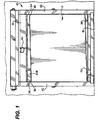
- Fig 1 discloses a high-speed door assembly 10 of the present invention. It will be appreciated by those of skill in the art that the present invention will also provide benefits for vertically moving doors which are neither high speed nor operated by motors or automated open/close circuitry.
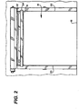
- assembly 10 includes a vertically moving door, having a door body 12, that permits and prohibits access through a door opening 14. Opening 14 is defined by a top 16, a bottom defined by a floor 18, and at least two sides 20, 22. Assembly 10 also includes a protective body 24.
- the door body 12 has an upper end 26 and a lower end 28.
- the lower end 28 When the door body 12 is in a closed position, the lower end 28 is located proximate the floor 18. In this position the lower end 28 of the door body 12 may contact and pick up debris in the form of solid or liquid. In applications where door body 12 separates areas of differing temperature and or humidity, the lower portion 28 may also have frost or sweat from the atmosphere as "debris.” Consequently, when in the door body 12 is in a partially open position this debris may fall onto objects and/or people passing through the opening 14 below.
- the door assembly 12 includes a protective body 24.
- the protective body 24 may be located proximate the top of the opening 14, as shown, in Figs. 1 and 2 , or attached proximate the lower end 28 of the door body 12, as shown in Figs. 3A-3C , or anywhere in between.
- the protective body 24 comprises at least one debris collecting surface 30 and opposing ends 32, 34 and is configured so as to be moveable between a first position under at least a portion of the door body lower end 28, when the door body 12 is in at least a partially open position as disclosed in Fig. 2 , and a second storage position as disclosed in Fig. 1 .
- the debris collecting surface 30 is in the first position, it is positioned such that any debris falling from the door body 12 is "caught" or collected by the surface and therefore prevented from falling onto the ground, or any people and/or objects below.
- the protective body 24 is configured such that debris in the form of liquid or solid collected on the debris collecting surface 30 will be urged toward one side 20 or 22 of the opening 14.
- the urging of fallen debris once collected on the protective body 24 towards one side can be accomplished by canting a portion of the protective body 24, as shown in Fig. 1 . Canting a portion the protective body allows gravity to facilitate the movement of debris from one end of the protective body 24 towards the other end of the protective body 24 when in the second position.
- a container may be provided under the lower end of protective body 24 allowing debris to enter the container.
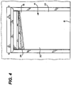
- gravity can facilitate the movement of debris when the protective body 24 is in the first position as well, as shown in Fig. 4 .
- the canting portion of the protective body 24 can be provided by dividing the debris collecting surface 30 into various portions creating an angled surface such as surface 30B. As shown, e.g. in Figs. 5A-C and 6 , the canting of the protective body 24 can be accomplished by dividing the debris collecting surface 30 into three separate portions 30A, 30B, and 30C. As shown, in Figs. 5A-C and 6 , the canted portion 30B of the debris collecting surface 24 is substantially horizontal to the ground in the first position, as shown e.g. in Fig. 2 where surface 30B is on the opposite side of 30C. and is thus only canted towards one end when the protective body is in the second position, shown in, for e.g., Figs, 1 , 5A-C , and 6 .
- the protective body 24 can be cither rotationally (shown e.g. Figs. 1 , 2 , 3A-C ) or translationally (shown in Figs. 7A and 7B ) moved from the first to the second position.
- the protective body 24 is translationally moved from the first to second position in a substantially horizontal fashion, as shown in Figs. 7A and 7B , it should be appreciated by those in the art that there is no need to provide a canted a portion of the protective body 24.
- the debris collecting surface 30 remains substantially horizontal to the floor and therefore does not allow debris to fall in either the first or second position.
- canting a portion of the protective body 24 to prevent debris from falling when in the second position is superfluous as the second position in such an embodiment does not facilitate the movement of debris towards the floor.
- an actuator is used.
- the actuator may be a hydraulic cylinder 40 rotating the protective body 24.
- the actuator can also be a solenoid, a linear variable differential transformer, or any similar devices which can facilitate the movement of the protective body 24.
- an electronic controller can be used to control the electronic device moving the protective body 24 between the first and second positions and that such a controller can be logistically coordinated with an automated door control system.
- the combination of a mechanical arm 42 attached to the protective body 24 and gravity can provide suitable actuation.
- the protective body 24 is attached proximate the lower end 28 of the door body 12 via swing arm 44 pivotable around a pivot point 46.
- attaching protective body 24 in such a manner allows protective body to remain in the first position underneath the lower end 28 of door body 12 during substantially the entire opening/fully open/closing cycle.
- Fig. 7A attaching protective body 24 in such a manner allows protective body to remain in the first position underneath the lower end 28 of door body 12 during substantially the entire opening/fully open/closing cycle.
- a surface 48 is attached proximate the lower end 28 of door body 12. As door body 12 approaches the top 16 of opening 14, the surface 50 engages portion 52 of the debris collecting surface 30.
- the surface 48 attached to the lower end 28 is positioned such that when door body 12 is in the fully open position, the surface 48 remains engaged with protective body 12, thereby holding the protective body 24 in the first position underneath door body 12. In such an embodiment, as the door body 12 is lowered, the surface 48 disengages, releasing the protective body 24, allowing it to return to the second position, out of the path of the door body 12.
- the high-speed door assembly 10 may further be provided with means for reducing bacterial or viral growth.
- One such means is disclosed as ultra-violet light source 60 shown in Fig. 9 .
- the ultra-violet light source 60 can be attached directly to the protective body 24 or a light attachment surface 62 may be attached to the protective body 24. Using either attachment method, the ultra-violet light source 60 should be attached in a manner that allows the emitted ultra-violet light 64 to impinge on at least a portion of collected debris on the debris collecting surface 30.
- the ultra-violet light source 60 may take the form of light-emitting diodes, which can be operated using either direct-current or alternating-current.
- the high-speed door assembly 10 may further include a second protective body 70 for collecting liquid run-off from condensation on the door body 12.
- the second protective body 70 is preferably attached proximate the lower end 28, as shown in Fig. 1 .
- the second protective body 70 is canted from one end towards its other end so gravity facilitates the movement of liquid debris towards the lower end.
- the canted end of the second protective body 70 in embodiments without a container to collect fluids or other debris, it can be advantageous for the canted end of the second protective body 70 to be located on the same side of opening 14 as protective body 24. This allows for easier clean up, as debris will all collect on one side of opening 14.
Landscapes
- Engineering & Computer Science (AREA)
- Structural Engineering (AREA)
- Civil Engineering (AREA)
- Health & Medical Sciences (AREA)
- Architecture (AREA)
- Life Sciences & Earth Sciences (AREA)
- Epidemiology (AREA)
- Animal Behavior & Ethology (AREA)
- General Health & Medical Sciences (AREA)
- Public Health (AREA)
- Veterinary Medicine (AREA)
- Specific Sealing Or Ventilating Devices For Doors And Windows (AREA)
- Power-Operated Mechanisms For Wings (AREA)
Description
- The present invention relates to a door assembly which opens and closes vertically, and more specifically, to means for preventing debris falling from a lower portion of the door when the door is in an at least partially open position.
- Overhead-doors are typically sealed by contacting a lower portion, typically the bottom edge portion of the door, and perhaps a seal, with the floor. However in many applications this can pose a problem where debris is located on the floor beneath the door because, when the door is closed against the floor, the bottom of the door and/or seal can come into contact with the debris. Also, debris in many forms including condensed moisture can contaminate the lower portion of the door by various means. Accordingly, when the door is opened, there is the potential for this debris to fall from the bottom portions or leading edge of the door and/or seal onto objects (e.g. food) and/or people passing through the doorway.
- In order to prevent such debris from falling onto objects and/or people passing beneath the door, the Applicant of this invention has previously provided a protective body consisting of essentially a collection surface connected to a pneumatic cylinder. When the door is fully opened, the protective body substantially spans the width of the door and collects debris that falls while the door is fully open. When using this protective body however, as the door begins to close, the protective body is rotated from a position where the collection surface is substantially horizontal to the floor to a position that is substantially perpendicular to the floor. This leads to a situation where debris collected on the protective body will drop onto objects and/or people or the floor below when the guard is moved out of the path of the door. So while protection of contamination by debris dropping is provided during the fully open time of the door, during opening and closing, where traffic may still be in the door opening, contamination may occur.
-
EP 1 233 140 A1 discloses a roll-up overhead door for sanitary applications according to the preamble of claim 1. In this overhead door a drainage trough is attached to a bottom portion of the door panel. The trough collects moisture falling from the door. The drainage trough is configured such that drainage flows towards at least one end of the trough. - The present invention is directed towards structures and methods to solve these deficiencies and to provide new advantages in prevention of contaminating cargo or persons traversing the opening or passage while the door is still overhead.
- This problem is solved by a door assembly according to claim 1 and a method according to
claim 16. -
-
Fig. 1 is a front plan view exemplifying an embodiment of the present invention when the door is in a fully closed position; -
Fig. 2 is a front plan view exemplifying the embodiment ofFig. 1 when the door is in the fully open position; -
Figs. 3A-3C partial side plan views of the door ofFig. 1 exemplifying the progression of movement of a protective body according to the invention; -
Fig. 4 is a front plan view of a door having an embodiment similar toFig. 1 but with a steeper angle employed on a protective body according to the invention; -
Fig. 5A-5C show various views of an embodiment of a protective body according to the present invention; -
Fig. 6 is a partial plan view of an embodiment of the present invention; -
Figs. 7A-7B are schematic side views showing a door according to the invention in relatively opened and closed positions; -
Figs. 8A-8D are partial side plan views exemplifying a progression of movement for an embodiment of the present invention; and, -
Fig. 9 is a schematic side in partial of another embodiment of the present invention. - While the present invention is susceptible of embodiment in many different forms, there is shown in the drawings and will herein be described in detail preferred embodiments of the invention with the understanding that the present disclosure is to be considered as an exemplification of the principles of the invention and is not intended to limit the broad aspect of the invention to the embodiments illustrated.
-
Fig 1 discloses a high-speed door assembly 10 of the present invention. It will be appreciated by those of skill in the art that the present invention will also provide benefits for vertically moving doors which are neither high speed nor operated by motors or automated open/close circuitry. - As disclosed in
Fig. 2 assembly 10 includes a vertically moving door, having adoor body 12, that permits and prohibits access through a door opening 14.Opening 14 is defined by atop 16, a bottom defined by afloor 18, and at least twosides Assembly 10 also includes aprotective body 24. - As disclosed in
Fig. 1 , thedoor body 12 has anupper end 26 and alower end 28. When thedoor body 12 is in a closed position, thelower end 28 is located proximate thefloor 18. In this position thelower end 28 of thedoor body 12 may contact and pick up debris in the form of solid or liquid. In applications wheredoor body 12 separates areas of differing temperature and or humidity, thelower portion 28 may also have frost or sweat from the atmosphere as "debris." Consequently, when in thedoor body 12 is in a partially open position this debris may fall onto objects and/or people passing through theopening 14 below. - In order to prevent the debris from falling on objects and/or people as they pass through the
opening 14, thedoor assembly 12 includes aprotective body 24. Theprotective body 24 may be located proximate the top of theopening 14, as shown, inFigs. 1 and2 , or attached proximate thelower end 28 of thedoor body 12, as shown inFigs. 3A-3C , or anywhere in between. - The
protective body 24 comprises at least onedebris collecting surface 30 and opposingends lower end 28, when thedoor body 12 is in at least a partially open position as disclosed inFig. 2 , and a second storage position as disclosed inFig. 1 . Stated another way, when thedebris collecting surface 30 is in the first position, it is positioned such that any debris falling from thedoor body 12 is "caught" or collected by the surface and therefore prevented from falling onto the ground, or any people and/or objects below. As seen inFig. 1 , theprotective body 24 is configured such that debris in the form of liquid or solid collected on thedebris collecting surface 30 will be urged toward oneside opening 14. - The urging of fallen debris once collected on the
protective body 24 towards one side can be accomplished by canting a portion of theprotective body 24, as shown inFig. 1 . Canting a portion the protective body allows gravity to facilitate the movement of debris from one end of theprotective body 24 towards the other end of theprotective body 24 when in the second position. In an alternative embodiment, a container may be provided under the lower end ofprotective body 24 allowing debris to enter the container. In any embodiment, it should be appreciated that by canting different portions of theprotective body 24, gravity can facilitate the movement of debris when theprotective body 24 is in the first position as well, as shown inFig. 4 . - The canting portion of the
protective body 24 can be provided by dividing thedebris collecting surface 30 into various portions creating an angled surface such assurface 30B. As shown, e.g. inFigs. 5A-C and 6 , the canting of theprotective body 24 can be accomplished by dividing thedebris collecting surface 30 into threeseparate portions Figs. 5A-C and 6 , the cantedportion 30B of thedebris collecting surface 24 is substantially horizontal to the ground in the first position, as shown e.g. inFig. 2 wheresurface 30B is on the opposite side of 30C. and is thus only canted towards one end when the protective body is in the second position, shown in, for e.g.,Figs, 1 ,5A-C , and6 . - The
protective body 24 can be cither rotationally (shown e.g.Figs. 1 ,2 ,3A-C ) or translationally (shown inFigs. 7A and 7B ) moved from the first to the second position. In embodiments where theprotective body 24 is translationally moved from the first to second position in a substantially horizontal fashion, as shown inFigs. 7A and 7B , it should be appreciated by those in the art that there is no need to provide a canted a portion of theprotective body 24. When using a translation movement, thedebris collecting surface 30 remains substantially horizontal to the floor and therefore does not allow debris to fall in either the first or second position. As such, canting a portion of theprotective body 24 to prevent debris from falling when in the second position is superfluous as the second position in such an embodiment does not facilitate the movement of debris towards the floor. - In order to facilitate the movement of the protective body, an actuator is used. As shown in
Figs. 1 and6 , the actuator may be ahydraulic cylinder 40 rotating theprotective body 24. However it should be appreciated that the actuator can also be a solenoid, a linear variable differential transformer, or any similar devices which can facilitate the movement of theprotective body 24. When using an electronic actuator, it should be appreciated by those in the art that an electronic controller can be used to control the electronic device moving theprotective body 24 between the first and second positions and that such a controller can be logistically coordinated with an automated door control system. - In an alternative embodiment, shown in
Figs. 3A-C , the combination of amechanical arm 42 attached to theprotective body 24 and gravity can provide suitable actuation. In this alternative embodiment, theprotective body 24 is attached proximate thelower end 28 of thedoor body 12 viaswing arm 44 pivotable around apivot point 46. As shown inFig. 7A , attachingprotective body 24 in such a manner allows protective body to remain in the first position underneath thelower end 28 ofdoor body 12 during substantially the entire opening/fully open/closing cycle. As shown inFig. 7B , as thelower end 28 of thedoor body 12 approaches the bottom of the opening defined by thefloor 18,mechanical arm 42 contacts thefloor 18 causing the protective body24 to lift and rotate out of the way ofdoor body 12 so as to permit the door body edge portions to seal against thefloor 18. It should be appreciated by those of skill in the art that other mechanical means, e.g. wheels, additional pivot points, etc., can be used either alone or in conjunction with themechanical arm 42 to moveprotective body 24 asdoor body 12 closes. When thedoor body 12 is in the fully closed position, shown inFig. 3C , theprotective body 12 is substantially held off thefloor 18 bymechanical arm 42. This embodiment has the added advantage of not only protecting objects and/or people as they pass through the opening, it also has the advantage of preventing any debris from falling to the floor in the opening as the door opens and closes creating a safer passageway. - In yet another embodiment of the present invention, shown in
Figs. 8A-D , the combination of asurface 48, gravity, andpivot point 50 can provide suitable actuation to move theprotective body 24. As shown inFigs. 8A-D , asurface 50 is attached proximate thelower end 28 ofdoor body 12. Asdoor body 12 approaches the top 16 ofopening 14, thesurface 50 engagesportion 52 of thedebris collecting surface 30. Thesurface 48 attached to thelower end 28 is positioned such that whendoor body 12 is in the fully open position, thesurface 48 remains engaged withprotective body 12, thereby holding theprotective body 24 in the first position underneathdoor body 12. In such an embodiment, as thedoor body 12 is lowered, thesurface 48 disengages, releasing theprotective body 24, allowing it to return to the second position, out of the path of thedoor body 12. - Since some environments and applications of vertically moving doors, require higher standards of cleanliness, it may be desirable to treat collected debris that may not be removed by a canting of a collection surface. To meet this requirement, the high-
speed door assembly 10 may further be provided with means for reducing bacterial or viral growth. One such means is disclosed as ultra-violetlight source 60 shown inFig. 9 . The ultra-violetlight source 60 can be attached directly to theprotective body 24 or alight attachment surface 62 may be attached to theprotective body 24. Using either attachment method, the ultra-violetlight source 60 should be attached in a manner that allows the emitted ultra-violet light 64 to impinge on at least a portion of collected debris on thedebris collecting surface 30. The ultra-violetlight source 60 may take the form of light-emitting diodes, which can be operated using either direct-current or alternating-current. - The high-
speed door assembly 10 may further include a secondprotective body 70 for collecting liquid run-off from condensation on thedoor body 12. The secondprotective body 70 is preferably attached proximate thelower end 28, as shown inFig. 1 . As shown inFig. 1 , the secondprotective body 70 is canted from one end towards its other end so gravity facilitates the movement of liquid debris towards the lower end. As shown inFig. 1 , in embodiments without a container to collect fluids or other debris, it can be advantageous for the canted end of the secondprotective body 70 to be located on the same side of opening 14 asprotective body 24. This allows for easier clean up, as debris will all collect on one side ofopening 14.
Claims (16)
- A door assembly (10) including a vertically moving door to permit and prohibit access through an opening (14) which has a top (16), a bottom defined by a floor (18), and at least two sides (20, 22), the door assembly comprising:a door body (12) having upper (26) and lower portions (28), and being mounted proximate the opening such that the lower portion is proximate the floor when the door body (12) is in a closed position;a protective body (24) configured in connection with the door body (12), the protective body (24) having at least one debris collecting surface (30) and opposing ends (32,34), the protective body being configured such that debris collected on the debris collecting surface will be urged toward one of the opposing ends,characterized in thatthe protective body (24) is moveable between a first position under at least a portion of the door body lower portion when the door body (12) is in at least a partially open position and a second storage position; and in thatthe door assembly further comprises an actuator (40, 42, 48) for moving the protective body (24) between the first position and the second position.
- The door assembly of Claim 1 wherein the protective body (24) is located proximate the top (16) of the opening (14).
- The door assembly of Claim 1 wherein the protective body (24) is attached to the lower end of the door panel.
- The door assembly of Claims 1-3 wherein at least a portion (30B) of the protective body (24) is canted from one of its ends towards the other so gravity facilitates the movement of debris towards one side of the opening when the protective body is in a second position.
- The door assembly of Claims 1-4 wherein at least a portion (30B) of the debris collecting surface (30) is substantially horizontal to the floor in the first position and said portion of the debris collecting surface is canted towards one of its ends when the protective body is in the second position.
- The door assembly of Claims 1-5 wherein the protective body moves rotationally between the first and second positions.
- The door assembly of Claim 1-5 wherein the protective body moves translationally between the first and second positions.
- The door assembly of Claim 1 wherein the actuator for moving the protective body (24) is at least one from the group of: a hydraulic cylinder, a solenoid, and a linear variable differential transformer, an arm attached to the protective body, a body attached proximate 1he lower end of the door body.
- The door assembly of Claims 1-8, wherein the actuator for moving the protective body is controlled by an electronic controller.
- The door assembly of Claim 1-9 further comprising a container located such that when the protective body (24) is in the second position, debris may enter the container.
- The door assembly of Claim 1-10 further comprising an ultra-violet light source (60) situated such that ultra-violet light therefrom impinges on at least a portion of collected debris.
- The door assembly of Claim 11 wherein the ultra-violet light source is at least one light-emitting diode.
- The door assembly of Claims 1-12 further comprising a second protective body (70) having opposing ends and being non-moveably attached proximate the lower end of the door body.
- The door assembly of Claim 13 wherein the second protective (70) body is canted from one end towards its other end so gravity facilitates the movement of liquid debris towards the lower end.
- The door assembly of Claim 14 wherein the protective body (24) and the second protective body (70) are canted in such a manner as to facilitate the movement of debris in the same direction.
- A method for preventing substances from falling from a vertically moving door in an at least a partially open position, the method comprising the steps of:attaching a protective body (24) proximate the overhead door;characterized byattaching an actuator (40, 42, 48) for moving the protective body (24) between a first position under at least a portion of the door body (12) when the door is in at least partially open position and a second storage position;urging debris toward one end of the protective body (24).
Applications Claiming Priority (2)
| Application Number | Priority Date | Filing Date | Title |
|---|---|---|---|
| US20634209P | 2009-01-28 | 2009-01-28 | |
| PCT/US2010/022391 WO2010088376A1 (en) | 2009-01-28 | 2010-01-28 | Method and device for preventing contamination from a door which opens vertically |
Publications (3)
| Publication Number | Publication Date |
|---|---|
| EP2391792A1 EP2391792A1 (en) | 2011-12-07 |
| EP2391792A4 EP2391792A4 (en) | 2013-12-04 |
| EP2391792B1 true EP2391792B1 (en) | 2020-01-01 |
Family
ID=42395997
Family Applications (1)
| Application Number | Title | Priority Date | Filing Date |
|---|---|---|---|
| EP10736395.4A Active EP2391792B1 (en) | 2009-01-28 | 2010-01-28 | Method and device for preventing contamination from a door which opens vertically |
Country Status (7)
| Country | Link |
|---|---|
| US (2) | US8627605B2 (en) |
| EP (1) | EP2391792B1 (en) |
| CN (1) | CN102301085A (en) |
| BR (1) | BRPI1005325A2 (en) |
| CA (1) | CA2750568C (en) |
| MX (2) | MX339204B (en) |
| WO (1) | WO2010088376A1 (en) |
Families Citing this family (11)
| Publication number | Priority date | Publication date | Assignee | Title |
|---|---|---|---|---|
| BRPI1005325A2 (en) * | 2009-01-28 | 2016-02-10 | Rytec Corp | method and device for preventing contamination from a door which opens vertically |
| DE102012104039A1 (en) * | 2012-05-08 | 2013-11-14 | Efaflex Inzeniring D.O.O. Ljubljana | Hubtoranordnung and Torsturz-sealing device for this purpose |
| US9303448B2 (en) * | 2013-10-23 | 2016-04-05 | Zachary Dax Olkin | Flood shield systems and methods |
| US9121218B1 (en) * | 2014-11-26 | 2015-09-01 | Riaz Ladha | Garage door drip guard |
| US10180248B2 (en) | 2015-09-02 | 2019-01-15 | ProPhotonix Limited | LED lamp with sensing capabilities |
| US10526838B2 (en) | 2016-08-05 | 2020-01-07 | Osi Industries, Llc | Drainage assembly for an automatic door |
| EP4582665A3 (en) | 2018-11-30 | 2025-12-17 | Rytec Corporation | Door assembly having a soft bottomed door panel |
| US12144903B2 (en) * | 2020-04-27 | 2024-11-19 | Mechoshade Systems, Llc | Sanitizing window shade system |
| US11939039B2 (en) * | 2020-06-12 | 2024-03-26 | Federal Express Corporation | Aircraft door drainage system |
| IT202100029690A1 (en) * | 2021-11-24 | 2023-05-24 | Bmpeurope S R L | IMPROVEMENTS OF AN AIR SEAL DEVICE FOR A LIFTING CLOSURE |
| IT202100030011A1 (en) * | 2021-11-26 | 2023-05-26 | Bmpeurope S R L | CONDENSATION WATER DISPOSAL DEVICE OF A QUICK SLIDING ROLLER DOOR PLACED BETWEEN TWO ROOMS WITH DIFFERENT TEMPERATURES |
Family Cites Families (21)
| Publication number | Priority date | Publication date | Assignee | Title |
|---|---|---|---|---|
| US782468A (en) * | 1904-03-18 | 1905-02-14 | Frank C Roberts | Fireproof shutter. |
| US3115324A (en) * | 1961-10-09 | 1963-12-24 | Frank R Chapman | Gutter mounting |
| IT1053958B (en) * | 1975-02-14 | 1981-10-10 | Hattori Tadashi | IMPROVEMENT IN FIRE CUTTER AND FLAME CUTTER SYSTEMS FOR FIRE CONTAINMENT |
| SE459873B (en) * | 1986-10-09 | 1989-08-14 | Nomafa Ab | SAFETY DEVICE, IN PARTICULAR, FOR S ROLLPORTS |
| US4726151A (en) * | 1987-01-06 | 1988-02-23 | Vitale Benedetto A | Rain water leader/gutter adaptor |
| US5630459A (en) | 1995-03-09 | 1997-05-20 | Martin Door Manufacturing, Inc. | Shield apparatus and method for sectional door hinge |
| ES2194831T3 (en) * | 1997-07-25 | 2003-12-01 | Rytec Corp | DOOR-ELEVATED CURTAIN COIL FOR SANITARY APPLICATIONS. |
| EP1233140A1 (en) * | 1997-07-25 | 2002-08-21 | Rytec Corporation | Roll-up overhead door for sanitary applications |
| US6082046A (en) * | 1998-02-25 | 2000-07-04 | Simmons; Kevin A. | Overhead door sensor mounting bracket |
| US6176039B1 (en) * | 1999-11-22 | 2001-01-23 | Terry A. Craig | Garage door mounted object sensor system |
| US7204291B2 (en) * | 2001-04-10 | 2007-04-17 | Last Harry J | Modular lid and actuator for underwater pool cover drum enclosure |
| US6779581B2 (en) * | 2002-07-25 | 2004-08-24 | Louis Towley | Secondary physical/visual barrier |
| US20050247411A1 (en) * | 2004-05-04 | 2005-11-10 | Youngtak Shim | Door cover systems and methods |
| US7544291B2 (en) * | 2004-12-21 | 2009-06-09 | Ranco Incorporated Of Delaware | Water purification system utilizing a plurality of ultraviolet light emitting diodes |
| US7299848B2 (en) * | 2005-04-12 | 2007-11-27 | Smoke Guard, Inc. | Closure member control systems, including door control systems for barrier housings, and associated methods |
| US20070131872A1 (en) * | 2005-12-09 | 2007-06-14 | Shearer Jon D | Water-purification device for a potable water system |
| US7735539B2 (en) * | 2007-12-28 | 2010-06-15 | Nohara Guard System Co. Ltd. | Fire-resistant smoke-suppressant device |
| BRPI1005325A2 (en) * | 2009-01-28 | 2016-02-10 | Rytec Corp | method and device for preventing contamination from a door which opens vertically |
| US8113265B2 (en) * | 2009-03-02 | 2012-02-14 | Rite-Hite Holding Corporation | Washdown door |
| US20100314551A1 (en) * | 2009-06-11 | 2010-12-16 | Bettles Timothy J | In-line Fluid Treatment by UV Radiation |
| US9199864B2 (en) * | 2011-04-14 | 2015-12-01 | Empire Technology Development Llc | Ultraviolet water sterilization |
-
2010
- 2010-01-28 BR BRPI1005325A patent/BRPI1005325A2/en not_active IP Right Cessation
- 2010-01-28 CA CA2750568A patent/CA2750568C/en active Active
- 2010-01-28 WO PCT/US2010/022391 patent/WO2010088376A1/en not_active Ceased
- 2010-01-28 MX MX2014002372A patent/MX339204B/en unknown
- 2010-01-28 US US13/146,874 patent/US8627605B2/en active Active
- 2010-01-28 MX MX2011007906A patent/MX2011007906A/en active IP Right Grant
- 2010-01-28 EP EP10736395.4A patent/EP2391792B1/en active Active
- 2010-01-28 CN CN2010800056740A patent/CN102301085A/en active Pending
-
2013
- 2013-12-23 US US14/138,488 patent/US9186427B2/en active Active
Non-Patent Citations (1)
| Title |
|---|
| None * |
Also Published As
| Publication number | Publication date |
|---|---|
| CN102301085A (en) | 2011-12-28 |
| US20110283620A1 (en) | 2011-11-24 |
| US20140102004A1 (en) | 2014-04-17 |
| BRPI1005325A2 (en) | 2016-02-10 |
| MX339204B (en) | 2016-05-16 |
| US9186427B2 (en) | 2015-11-17 |
| WO2010088376A1 (en) | 2010-08-05 |
| MX2011007906A (en) | 2011-08-17 |
| US8627605B2 (en) | 2014-01-14 |
| CA2750568A1 (en) | 2010-08-05 |
| EP2391792A4 (en) | 2013-12-04 |
| EP2391792A1 (en) | 2011-12-07 |
| CA2750568C (en) | 2017-11-28 |
Similar Documents
| Publication | Publication Date | Title |
|---|---|---|
| CA2750568C (en) | Method and device for preventing contamination from a door which opens vertically | |
| US20040206004A1 (en) | Seal for a bi-parting door | |
| EP1935311A1 (en) | Floor cleaning device | |
| CN201329362Y (en) | Moving top-draft soot collector travelling on vertical railway | |
| US6736353B1 (en) | Grooved profile for diverting liquid | |
| CN101832090A (en) | Warehouse and automatic ventilation control system thereof | |
| US20080163799A1 (en) | Safety workbench having easy-to-clean front pane | |
| CA2546344A1 (en) | Conveyor oven with energy saving baffle mechanism and method | |
| CN109250338B (en) | Electric garbage bucket-turning window with lifting function | |
| KR101649875B1 (en) | Automatic drainage system for paddy field | |
| CN117462360B (en) | An intelligent double-layer box-type dissection table capable of interchangeable positions | |
| US7077618B2 (en) | Device for lifting and removing oven doors of a cooking oven | |
| CN206265920U (en) | Switching grain Intelligent mobile dust arrester | |
| US4851114A (en) | Cleaning apparatus for bar screen | |
| CN207177635U (en) | A kind of novel high speed industrial lift door | |
| EP1292796A1 (en) | Extractor hood device | |
| CN208875208U (en) | A kind of efficient mousetrap | |
| CN210508972U (en) | Automatic gate of lathe with monitor function | |
| CN219585007U (en) | Higher rubbish of security is put in door | |
| CN208962158U (en) | Blower accessory automatic punch | |
| CN116174425B (en) | Powder cleaning device for inner wall of powder material transport vehicle tank | |
| CN223888680U (en) | A side-suction and top-suction zinc fume collection device | |
| RU2280728C1 (en) | All-purpose pneumatic railway cleansing vehicle | |
| CN217043922U (en) | Novel zinc smoke collecting door cover | |
| CN1942556A (en) | Coke oven manipulating machine |
Legal Events
| Date | Code | Title | Description |
|---|---|---|---|
| PUAI | Public reference made under article 153(3) epc to a published international application that has entered the european phase |
Free format text: ORIGINAL CODE: 0009012 |
|
| 17P | Request for examination filed |
Effective date: 20110818 |
|
| AK | Designated contracting states |
Kind code of ref document: A1 Designated state(s): AT BE BG CH CY CZ DE DK EE ES FI FR GB GR HR HU IE IS IT LI LT LU LV MC MK MT NL NO PL PT RO SE SI SK SM TR |
|
| DAX | Request for extension of the european patent (deleted) | ||
| A4 | Supplementary search report drawn up and despatched |
Effective date: 20131104 |
|
| RIC1 | Information provided on ipc code assigned before grant |
Ipc: E06B 9/17 20060101AFI20131028BHEP Ipc: E06B 9/13 20060101ALI20131028BHEP |
|
| 17Q | First examination report despatched |
Effective date: 20140724 |
|
| STAA | Information on the status of an ep patent application or granted ep patent |
Free format text: STATUS: EXAMINATION IS IN PROGRESS |
|
| GRAP | Despatch of communication of intention to grant a patent |
Free format text: ORIGINAL CODE: EPIDOSNIGR1 |
|
| STAA | Information on the status of an ep patent application or granted ep patent |
Free format text: STATUS: GRANT OF PATENT IS INTENDED |
|
| RIN1 | Information on inventor provided before grant (corrected) |
Inventor name: DRIFKA, BRIAN NORBERT |
|
| INTG | Intention to grant announced |
Effective date: 20190619 |
|
| GRAJ | Information related to disapproval of communication of intention to grant by the applicant or resumption of examination proceedings by the epo deleted |
Free format text: ORIGINAL CODE: EPIDOSDIGR1 |
|
| STAA | Information on the status of an ep patent application or granted ep patent |
Free format text: STATUS: EXAMINATION IS IN PROGRESS |
|
| INTC | Intention to grant announced (deleted) | ||
| GRAR | Information related to intention to grant a patent recorded |
Free format text: ORIGINAL CODE: EPIDOSNIGR71 |
|
| GRAS | Grant fee paid |
Free format text: ORIGINAL CODE: EPIDOSNIGR3 |
|
| STAA | Information on the status of an ep patent application or granted ep patent |
Free format text: STATUS: GRANT OF PATENT IS INTENDED |
|
| GRAA | (expected) grant |
Free format text: ORIGINAL CODE: 0009210 |
|
| STAA | Information on the status of an ep patent application or granted ep patent |
Free format text: STATUS: THE PATENT HAS BEEN GRANTED |
|
| INTG | Intention to grant announced |
Effective date: 20191120 |
|
| AK | Designated contracting states |
Kind code of ref document: B1 Designated state(s): AT BE BG CH CY CZ DE DK EE ES FI FR GB GR HR HU IE IS IT LI LT LU LV MC MK MT NL NO PL PT RO SE SI SK SM TR |
|
| REG | Reference to a national code |
Ref country code: GB Ref legal event code: FG4D |
|
| REG | Reference to a national code |
Ref country code: CH Ref legal event code: EP Ref country code: AT Ref legal event code: REF Ref document number: 1219970 Country of ref document: AT Kind code of ref document: T Effective date: 20200115 |
|
| REG | Reference to a national code |
Ref country code: DE Ref legal event code: R096 Ref document number: 602010062611 Country of ref document: DE |
|
| REG | Reference to a national code |
Ref country code: IE Ref legal event code: FG4D |
|
| REG | Reference to a national code |
Ref country code: SE Ref legal event code: TRGR |
|
| REG | Reference to a national code |
Ref country code: NL Ref legal event code: FP |
|
| REG | Reference to a national code |
Ref country code: LT Ref legal event code: MG4D |
|
| PG25 | Lapsed in a contracting state [announced via postgrant information from national office to epo] |
Ref country code: LT Free format text: LAPSE BECAUSE OF FAILURE TO SUBMIT A TRANSLATION OF THE DESCRIPTION OR TO PAY THE FEE WITHIN THE PRESCRIBED TIME-LIMIT Effective date: 20200101 Ref country code: FI Free format text: LAPSE BECAUSE OF FAILURE TO SUBMIT A TRANSLATION OF THE DESCRIPTION OR TO PAY THE FEE WITHIN THE PRESCRIBED TIME-LIMIT Effective date: 20200101 Ref country code: NO Free format text: LAPSE BECAUSE OF FAILURE TO SUBMIT A TRANSLATION OF THE DESCRIPTION OR TO PAY THE FEE WITHIN THE PRESCRIBED TIME-LIMIT Effective date: 20200401 Ref country code: PT Free format text: LAPSE BECAUSE OF FAILURE TO SUBMIT A TRANSLATION OF THE DESCRIPTION OR TO PAY THE FEE WITHIN THE PRESCRIBED TIME-LIMIT Effective date: 20200527 |
|
| PG25 | Lapsed in a contracting state [announced via postgrant information from national office to epo] |
Ref country code: HR Free format text: LAPSE BECAUSE OF FAILURE TO SUBMIT A TRANSLATION OF THE DESCRIPTION OR TO PAY THE FEE WITHIN THE PRESCRIBED TIME-LIMIT Effective date: 20200101 Ref country code: GR Free format text: LAPSE BECAUSE OF FAILURE TO SUBMIT A TRANSLATION OF THE DESCRIPTION OR TO PAY THE FEE WITHIN THE PRESCRIBED TIME-LIMIT Effective date: 20200402 Ref country code: LV Free format text: LAPSE BECAUSE OF FAILURE TO SUBMIT A TRANSLATION OF THE DESCRIPTION OR TO PAY THE FEE WITHIN THE PRESCRIBED TIME-LIMIT Effective date: 20200101 Ref country code: IS Free format text: LAPSE BECAUSE OF FAILURE TO SUBMIT A TRANSLATION OF THE DESCRIPTION OR TO PAY THE FEE WITHIN THE PRESCRIBED TIME-LIMIT Effective date: 20200501 Ref country code: BG Free format text: LAPSE BECAUSE OF FAILURE TO SUBMIT A TRANSLATION OF THE DESCRIPTION OR TO PAY THE FEE WITHIN THE PRESCRIBED TIME-LIMIT Effective date: 20200401 |
|
| REG | Reference to a national code |
Ref country code: CH Ref legal event code: PL |
|
| REG | Reference to a national code |
Ref country code: DE Ref legal event code: R097 Ref document number: 602010062611 Country of ref document: DE |
|
| PG25 | Lapsed in a contracting state [announced via postgrant information from national office to epo] |
Ref country code: RO Free format text: LAPSE BECAUSE OF FAILURE TO SUBMIT A TRANSLATION OF THE DESCRIPTION OR TO PAY THE FEE WITHIN THE PRESCRIBED TIME-LIMIT Effective date: 20200101 Ref country code: SK Free format text: LAPSE BECAUSE OF FAILURE TO SUBMIT A TRANSLATION OF THE DESCRIPTION OR TO PAY THE FEE WITHIN THE PRESCRIBED TIME-LIMIT Effective date: 20200101 Ref country code: ES Free format text: LAPSE BECAUSE OF FAILURE TO SUBMIT A TRANSLATION OF THE DESCRIPTION OR TO PAY THE FEE WITHIN THE PRESCRIBED TIME-LIMIT Effective date: 20200101 Ref country code: MC Free format text: LAPSE BECAUSE OF FAILURE TO SUBMIT A TRANSLATION OF THE DESCRIPTION OR TO PAY THE FEE WITHIN THE PRESCRIBED TIME-LIMIT Effective date: 20200101 Ref country code: SM Free format text: LAPSE BECAUSE OF FAILURE TO SUBMIT A TRANSLATION OF THE DESCRIPTION OR TO PAY THE FEE WITHIN THE PRESCRIBED TIME-LIMIT Effective date: 20200101 Ref country code: LU Free format text: LAPSE BECAUSE OF NON-PAYMENT OF DUE FEES Effective date: 20200128 Ref country code: EE Free format text: LAPSE BECAUSE OF FAILURE TO SUBMIT A TRANSLATION OF THE DESCRIPTION OR TO PAY THE FEE WITHIN THE PRESCRIBED TIME-LIMIT Effective date: 20200101 Ref country code: DK Free format text: LAPSE BECAUSE OF FAILURE TO SUBMIT A TRANSLATION OF THE DESCRIPTION OR TO PAY THE FEE WITHIN THE PRESCRIBED TIME-LIMIT Effective date: 20200101 |
|
| PLBE | No opposition filed within time limit |
Free format text: ORIGINAL CODE: 0009261 |
|
| STAA | Information on the status of an ep patent application or granted ep patent |
Free format text: STATUS: NO OPPOSITION FILED WITHIN TIME LIMIT |
|
| REG | Reference to a national code |
Ref country code: AT Ref legal event code: MK05 Ref document number: 1219970 Country of ref document: AT Kind code of ref document: T Effective date: 20200101 |
|
| PG25 | Lapsed in a contracting state [announced via postgrant information from national office to epo] |
Ref country code: LI Free format text: LAPSE BECAUSE OF NON-PAYMENT OF DUE FEES Effective date: 20200131 Ref country code: CH Free format text: LAPSE BECAUSE OF NON-PAYMENT OF DUE FEES Effective date: 20200131 |
|
| 26N | No opposition filed |
Effective date: 20201002 |
|
| PG25 | Lapsed in a contracting state [announced via postgrant information from national office to epo] |
Ref country code: AT Free format text: LAPSE BECAUSE OF FAILURE TO SUBMIT A TRANSLATION OF THE DESCRIPTION OR TO PAY THE FEE WITHIN THE PRESCRIBED TIME-LIMIT Effective date: 20200101 Ref country code: IE Free format text: LAPSE BECAUSE OF NON-PAYMENT OF DUE FEES Effective date: 20200128 Ref country code: IT Free format text: LAPSE BECAUSE OF FAILURE TO SUBMIT A TRANSLATION OF THE DESCRIPTION OR TO PAY THE FEE WITHIN THE PRESCRIBED TIME-LIMIT Effective date: 20200101 |
|
| PG25 | Lapsed in a contracting state [announced via postgrant information from national office to epo] |
Ref country code: SI Free format text: LAPSE BECAUSE OF FAILURE TO SUBMIT A TRANSLATION OF THE DESCRIPTION OR TO PAY THE FEE WITHIN THE PRESCRIBED TIME-LIMIT Effective date: 20200101 Ref country code: PL Free format text: LAPSE BECAUSE OF FAILURE TO SUBMIT A TRANSLATION OF THE DESCRIPTION OR TO PAY THE FEE WITHIN THE PRESCRIBED TIME-LIMIT Effective date: 20200101 |
|
| GBPC | Gb: european patent ceased through non-payment of renewal fee |
Effective date: 20200401 |
|
| PG25 | Lapsed in a contracting state [announced via postgrant information from national office to epo] |
Ref country code: GB Free format text: LAPSE BECAUSE OF NON-PAYMENT OF DUE FEES Effective date: 20200401 |
|
| PG25 | Lapsed in a contracting state [announced via postgrant information from national office to epo] |
Ref country code: TR Free format text: LAPSE BECAUSE OF FAILURE TO SUBMIT A TRANSLATION OF THE DESCRIPTION OR TO PAY THE FEE WITHIN THE PRESCRIBED TIME-LIMIT Effective date: 20200101 Ref country code: MT Free format text: LAPSE BECAUSE OF FAILURE TO SUBMIT A TRANSLATION OF THE DESCRIPTION OR TO PAY THE FEE WITHIN THE PRESCRIBED TIME-LIMIT Effective date: 20200101 Ref country code: CY Free format text: LAPSE BECAUSE OF FAILURE TO SUBMIT A TRANSLATION OF THE DESCRIPTION OR TO PAY THE FEE WITHIN THE PRESCRIBED TIME-LIMIT Effective date: 20200101 |
|
| PG25 | Lapsed in a contracting state [announced via postgrant information from national office to epo] |
Ref country code: MK Free format text: LAPSE BECAUSE OF FAILURE TO SUBMIT A TRANSLATION OF THE DESCRIPTION OR TO PAY THE FEE WITHIN THE PRESCRIBED TIME-LIMIT Effective date: 20200101 |
|
| PGFP | Annual fee paid to national office [announced via postgrant information from national office to epo] |
Ref country code: NL Payment date: 20260121 Year of fee payment: 17 |
|
| PGFP | Annual fee paid to national office [announced via postgrant information from national office to epo] |
Ref country code: SE Payment date: 20260121 Year of fee payment: 17 |
|
| PGFP | Annual fee paid to national office [announced via postgrant information from national office to epo] |
Ref country code: DE Payment date: 20260121 Year of fee payment: 17 |
|
| PGFP | Annual fee paid to national office [announced via postgrant information from national office to epo] |
Ref country code: BE Payment date: 20260121 Year of fee payment: 17 |
|
| PGFP | Annual fee paid to national office [announced via postgrant information from national office to epo] |
Ref country code: FR Payment date: 20260121 Year of fee payment: 17 |
|
| PGFP | Annual fee paid to national office [announced via postgrant information from national office to epo] |
Ref country code: CZ Payment date: 20260115 Year of fee payment: 17 |