EP2391744B1 - Beschichtung mit thermischen und nicht-thermischen beschichtungsverfahren - Google Patents
Beschichtung mit thermischen und nicht-thermischen beschichtungsverfahren Download PDFInfo
- Publication number
- EP2391744B1 EP2391744B1 EP10700522.5A EP10700522A EP2391744B1 EP 2391744 B1 EP2391744 B1 EP 2391744B1 EP 10700522 A EP10700522 A EP 10700522A EP 2391744 B1 EP2391744 B1 EP 2391744B1
- Authority
- EP
- European Patent Office
- Prior art keywords
- coating
- coating method
- thermal
- spraying
- layer
- Prior art date
- Legal status (The legal status is an assumption and is not a legal conclusion. Google has not performed a legal analysis and makes no representation as to the accuracy of the status listed.)
- Not-in-force
Links
- 238000000576 coating method Methods 0.000 title claims description 59
- 239000011248 coating agent Substances 0.000 title claims description 19
- 238000000034 method Methods 0.000 claims description 26
- 239000000463 material Substances 0.000 claims description 14
- 238000005507 spraying Methods 0.000 claims description 8
- 239000002002 slurry Substances 0.000 claims description 7
- 239000000758 substrate Substances 0.000 claims description 7
- 239000000919 ceramic Substances 0.000 claims description 6
- 238000007750 plasma spraying Methods 0.000 claims description 5
- 239000011230 binding agent Substances 0.000 claims description 4
- 238000007751 thermal spraying Methods 0.000 claims description 4
- 238000007749 high velocity oxygen fuel spraying Methods 0.000 claims description 3
- 239000010410 layer Substances 0.000 description 18
- 238000002485 combustion reaction Methods 0.000 description 16
- PXHVJJICTQNCMI-UHFFFAOYSA-N Nickel Chemical compound [Ni] PXHVJJICTQNCMI-UHFFFAOYSA-N 0.000 description 8
- 239000012720 thermal barrier coating Substances 0.000 description 8
- 229910017052 cobalt Inorganic materials 0.000 description 5
- 239000010941 cobalt Substances 0.000 description 5
- GUTLYIVDDKVIGB-UHFFFAOYSA-N cobalt atom Chemical compound [Co] GUTLYIVDDKVIGB-UHFFFAOYSA-N 0.000 description 5
- 239000013078 crystal Substances 0.000 description 5
- 229910000601 superalloy Inorganic materials 0.000 description 5
- 239000000203 mixture Substances 0.000 description 4
- 239000011241 protective layer Substances 0.000 description 4
- 229910045601 alloy Inorganic materials 0.000 description 3
- 239000000956 alloy Substances 0.000 description 3
- 238000001816 cooling Methods 0.000 description 3
- 230000007797 corrosion Effects 0.000 description 3
- 238000005260 corrosion Methods 0.000 description 3
- 229910052759 nickel Inorganic materials 0.000 description 3
- 230000003647 oxidation Effects 0.000 description 3
- 238000007254 oxidation reaction Methods 0.000 description 3
- 239000002245 particle Substances 0.000 description 3
- 239000007787 solid Substances 0.000 description 3
- 238000007711 solidification Methods 0.000 description 3
- 230000008023 solidification Effects 0.000 description 3
- XEEYBQQBJWHFJM-UHFFFAOYSA-N Iron Chemical compound [Fe] XEEYBQQBJWHFJM-UHFFFAOYSA-N 0.000 description 2
- 230000001680 brushing effect Effects 0.000 description 2
- BRPQOXSCLDDYGP-UHFFFAOYSA-N calcium oxide Chemical compound [O-2].[Ca+2] BRPQOXSCLDDYGP-UHFFFAOYSA-N 0.000 description 2
- 239000000292 calcium oxide Substances 0.000 description 2
- ODINCKMPIJJUCX-UHFFFAOYSA-N calcium oxide Inorganic materials [Ca]=O ODINCKMPIJJUCX-UHFFFAOYSA-N 0.000 description 2
- 238000005266 casting Methods 0.000 description 2
- 238000009826 distribution Methods 0.000 description 2
- 238000005566 electron beam evaporation Methods 0.000 description 2
- 229910052735 hafnium Inorganic materials 0.000 description 2
- VBJZVLUMGGDVMO-UHFFFAOYSA-N hafnium atom Chemical compound [Hf] VBJZVLUMGGDVMO-UHFFFAOYSA-N 0.000 description 2
- 239000007788 liquid Substances 0.000 description 2
- 239000000395 magnesium oxide Substances 0.000 description 2
- CPLXHLVBOLITMK-UHFFFAOYSA-N magnesium oxide Inorganic materials [Mg]=O CPLXHLVBOLITMK-UHFFFAOYSA-N 0.000 description 2
- AXZKOIWUVFPNLO-UHFFFAOYSA-N magnesium;oxygen(2-) Chemical compound [O-2].[Mg+2] AXZKOIWUVFPNLO-UHFFFAOYSA-N 0.000 description 2
- 239000000843 powder Substances 0.000 description 2
- 239000011253 protective coating Substances 0.000 description 2
- 230000035939 shock Effects 0.000 description 2
- 229910052710 silicon Inorganic materials 0.000 description 2
- 239000010703 silicon Substances 0.000 description 2
- 239000000126 substance Substances 0.000 description 2
- 229910052727 yttrium Inorganic materials 0.000 description 2
- VWQVUPCCIRVNHF-UHFFFAOYSA-N yttrium atom Chemical compound [Y] VWQVUPCCIRVNHF-UHFFFAOYSA-N 0.000 description 2
- RUDFQVOCFDJEEF-UHFFFAOYSA-N yttrium(III) oxide Inorganic materials [O-2].[O-2].[O-2].[Y+3].[Y+3] RUDFQVOCFDJEEF-UHFFFAOYSA-N 0.000 description 2
- YPFNIPKMNMDDDB-UHFFFAOYSA-K 2-[2-[bis(carboxylatomethyl)amino]ethyl-(2-hydroxyethyl)amino]acetate;iron(3+) Chemical compound [Fe+3].OCCN(CC([O-])=O)CCN(CC([O-])=O)CC([O-])=O YPFNIPKMNMDDDB-UHFFFAOYSA-K 0.000 description 1
- 241000191291 Abies alba Species 0.000 description 1
- 241000196324 Embryophyta Species 0.000 description 1
- 239000008186 active pharmaceutical agent Substances 0.000 description 1
- 238000005524 ceramic coating Methods 0.000 description 1
- 239000002826 coolant Substances 0.000 description 1
- 238000005242 forging Methods 0.000 description 1
- 239000000446 fuel Substances 0.000 description 1
- 238000009499 grossing Methods 0.000 description 1
- 238000004519 manufacturing process Methods 0.000 description 1
- 239000000155 melt Substances 0.000 description 1
- 229910001092 metal group alloy Inorganic materials 0.000 description 1
- 239000007769 metal material Substances 0.000 description 1
- 238000003801 milling Methods 0.000 description 1
- TWNQGVIAIRXVLR-UHFFFAOYSA-N oxo(oxoalumanyloxy)alumane Chemical compound O=[Al]O[Al]=O TWNQGVIAIRXVLR-UHFFFAOYSA-N 0.000 description 1
- 238000010248 power generation Methods 0.000 description 1
- 230000001681 protective effect Effects 0.000 description 1
- 238000009419 refurbishment Methods 0.000 description 1
- 238000005488 sandblasting Methods 0.000 description 1
- 238000005245 sintering Methods 0.000 description 1
- 239000002904 solvent Substances 0.000 description 1
- 230000035882 stress Effects 0.000 description 1
- 230000008646 thermal stress Effects 0.000 description 1
- 230000007704 transition Effects 0.000 description 1
Images


Classifications
-
- F—MECHANICAL ENGINEERING; LIGHTING; HEATING; WEAPONS; BLASTING
- F01—MACHINES OR ENGINES IN GENERAL; ENGINE PLANTS IN GENERAL; STEAM ENGINES
- F01D—NON-POSITIVE DISPLACEMENT MACHINES OR ENGINES, e.g. STEAM TURBINES
- F01D5/00—Blades; Blade-carrying members; Heating, heat-insulating, cooling or antivibration means on the blades or the members
- F01D5/12—Blades
- F01D5/28—Selecting particular materials; Particular measures relating thereto; Measures against erosion or corrosion
- F01D5/288—Protective coatings for blades
-
- C—CHEMISTRY; METALLURGY
- C23—COATING METALLIC MATERIAL; COATING MATERIAL WITH METALLIC MATERIAL; CHEMICAL SURFACE TREATMENT; DIFFUSION TREATMENT OF METALLIC MATERIAL; COATING BY VACUUM EVAPORATION, BY SPUTTERING, BY ION IMPLANTATION OR BY CHEMICAL VAPOUR DEPOSITION, IN GENERAL; INHIBITING CORROSION OF METALLIC MATERIAL OR INCRUSTATION IN GENERAL
- C23C—COATING METALLIC MATERIAL; COATING MATERIAL WITH METALLIC MATERIAL; SURFACE TREATMENT OF METALLIC MATERIAL BY DIFFUSION INTO THE SURFACE, BY CHEMICAL CONVERSION OR SUBSTITUTION; COATING BY VACUUM EVAPORATION, BY SPUTTERING, BY ION IMPLANTATION OR BY CHEMICAL VAPOUR DEPOSITION, IN GENERAL
- C23C24/00—Coating starting from inorganic powder
- C23C24/02—Coating starting from inorganic powder by application of pressure only
- C23C24/04—Impact or kinetic deposition of particles
-
- C—CHEMISTRY; METALLURGY
- C23—COATING METALLIC MATERIAL; COATING MATERIAL WITH METALLIC MATERIAL; CHEMICAL SURFACE TREATMENT; DIFFUSION TREATMENT OF METALLIC MATERIAL; COATING BY VACUUM EVAPORATION, BY SPUTTERING, BY ION IMPLANTATION OR BY CHEMICAL VAPOUR DEPOSITION, IN GENERAL; INHIBITING CORROSION OF METALLIC MATERIAL OR INCRUSTATION IN GENERAL
- C23C—COATING METALLIC MATERIAL; COATING MATERIAL WITH METALLIC MATERIAL; SURFACE TREATMENT OF METALLIC MATERIAL BY DIFFUSION INTO THE SURFACE, BY CHEMICAL CONVERSION OR SUBSTITUTION; COATING BY VACUUM EVAPORATION, BY SPUTTERING, BY ION IMPLANTATION OR BY CHEMICAL VAPOUR DEPOSITION, IN GENERAL
- C23C4/00—Coating by spraying the coating material in the molten state, e.g. by flame, plasma or electric discharge
- C23C4/04—Coating by spraying the coating material in the molten state, e.g. by flame, plasma or electric discharge characterised by the coating material
- C23C4/06—Metallic material
- C23C4/073—Metallic material containing MCrAl or MCrAlY alloys, where M is nickel, cobalt or iron, with or without non-metal elements
-
- C—CHEMISTRY; METALLURGY
- C23—COATING METALLIC MATERIAL; COATING MATERIAL WITH METALLIC MATERIAL; CHEMICAL SURFACE TREATMENT; DIFFUSION TREATMENT OF METALLIC MATERIAL; COATING BY VACUUM EVAPORATION, BY SPUTTERING, BY ION IMPLANTATION OR BY CHEMICAL VAPOUR DEPOSITION, IN GENERAL; INHIBITING CORROSION OF METALLIC MATERIAL OR INCRUSTATION IN GENERAL
- C23C—COATING METALLIC MATERIAL; COATING MATERIAL WITH METALLIC MATERIAL; SURFACE TREATMENT OF METALLIC MATERIAL BY DIFFUSION INTO THE SURFACE, BY CHEMICAL CONVERSION OR SUBSTITUTION; COATING BY VACUUM EVAPORATION, BY SPUTTERING, BY ION IMPLANTATION OR BY CHEMICAL VAPOUR DEPOSITION, IN GENERAL
- C23C4/00—Coating by spraying the coating material in the molten state, e.g. by flame, plasma or electric discharge
- C23C4/04—Coating by spraying the coating material in the molten state, e.g. by flame, plasma or electric discharge characterised by the coating material
- C23C4/10—Oxides, borides, carbides, nitrides or silicides; Mixtures thereof
- C23C4/11—Oxides
-
- C—CHEMISTRY; METALLURGY
- C23—COATING METALLIC MATERIAL; COATING MATERIAL WITH METALLIC MATERIAL; CHEMICAL SURFACE TREATMENT; DIFFUSION TREATMENT OF METALLIC MATERIAL; COATING BY VACUUM EVAPORATION, BY SPUTTERING, BY ION IMPLANTATION OR BY CHEMICAL VAPOUR DEPOSITION, IN GENERAL; INHIBITING CORROSION OF METALLIC MATERIAL OR INCRUSTATION IN GENERAL
- C23C—COATING METALLIC MATERIAL; COATING MATERIAL WITH METALLIC MATERIAL; SURFACE TREATMENT OF METALLIC MATERIAL BY DIFFUSION INTO THE SURFACE, BY CHEMICAL CONVERSION OR SUBSTITUTION; COATING BY VACUUM EVAPORATION, BY SPUTTERING, BY ION IMPLANTATION OR BY CHEMICAL VAPOUR DEPOSITION, IN GENERAL
- C23C4/00—Coating by spraying the coating material in the molten state, e.g. by flame, plasma or electric discharge
- C23C4/18—After-treatment
-
- Y—GENERAL TAGGING OF NEW TECHNOLOGICAL DEVELOPMENTS; GENERAL TAGGING OF CROSS-SECTIONAL TECHNOLOGIES SPANNING OVER SEVERAL SECTIONS OF THE IPC; TECHNICAL SUBJECTS COVERED BY FORMER USPC CROSS-REFERENCE ART COLLECTIONS [XRACs] AND DIGESTS
- Y02—TECHNOLOGIES OR APPLICATIONS FOR MITIGATION OR ADAPTATION AGAINST CLIMATE CHANGE
- Y02T—CLIMATE CHANGE MITIGATION TECHNOLOGIES RELATED TO TRANSPORTATION
- Y02T50/00—Aeronautics or air transport
- Y02T50/60—Efficient propulsion technologies, e.g. for aircraft
Definitions
- the invention relates to the coating of a component, in which a first and a second coating method is used successively.
- Components are often coated to protect the underlying substrate from corrosion, oxidation or heat.
- the European application EP 1 088 908 A2 discloses a method of smoothing the surface of a protective layer by means of a slurry layer.
- the object is achieved by a coating method in which, after the first, in particular thermal, coating method, a second, in particular a non-thermal, coating method is used, in order to apply coating material to a location which is difficult to access or easy to repair.
- FIG. 1 on the left a component 1, 120, 130, 155 is shown.
- the component 1 has a substrate 4, which consists in particular of turbine blades 120, 130 of a nickel- or cobalt-based superalloy.
- one or more coatings 7 are applied. These may be metallic protective coatings 7 (MCrAlX) and / or ceramic layers 7.
- the coating 7, which in particular represents the outermost layer of the layer system, has at one point a local irregularity 10 or a location 20 which is difficult to access. This may preferably be an unobtainable required layer thickness or preferably places where no coating is present.
- the layer 7 has been applied in the first step by a first coating method, in particular a thermal spraying method such as preferably plasma spraying, HVOF or cold gas spraying.
- the first coating process preferably constitutes an automated or semi-automated coating process in a plant in which the substrate 4 is installed in a coating operation and then coated according to a selected program.
- material 13 is additionally applied to the local location 10 by means of a second coating method, which eliminates the local irregularity 10.
- the location 10 is never the area that was coated by the first coating process.
- the second coating method unlike the first coating method, is a local coating method for repair.
- ceramic is applied locally to ceramic, so coating material in the second Coating process applied to a layer that has already been produced by the first coating process.
- the material 13 is applied by a second, different from the first, in particular non-thermal coating method.
- the second method is no plasma spraying, no CVD, no PVD, no HVOF and no cold gas spraying.
- the second coating process is a slurry application or slurry spraying.
- the slurry preferably has the same chemical composition for the powder (coating material) as the material which was also used in the first coating.
- the same particle size distribution is used as in the first coating.
- Most preferably, a somewhat smaller particle size distribution is used (ie the mean particle size is measurably smaller).
- non-thermal refers to the temperature of applying material to a substrate, i. whether the material is heated during the application ( ⁇ 100 ° C, in particular> 300 ° C) and not on subsequent steps after the application such. a debinding step or sintering.
- the second coating method is preferably a manual coating method (brushing, pouring, brushing, spraying, etc.).
- a slip is a mixture of a powder and at least one liquid (solvent) and possibly a binder.
- the existing binder is debinded and / or compacted in use and offsets or eliminates the unevenness.
- the FIG. 2 shows by way of example a gas turbine 100 in a longitudinal partial section.
- the gas turbine 100 has inside a rotatably mounted about a rotation axis 102 rotor 103 with a shaft, which is also referred to as a turbine runner.
- a compressor 105 for example, a toroidal combustion chamber 110, in particular annular combustion chamber, with a plurality of coaxially arranged burners 107, a turbine 108 and the exhaust housing 109th
- the annular combustion chamber 110 communicates with an annular annular hot gas channel 111, for example.
- Each turbine stage 112 is formed, for example, from two blade rings. As seen in the direction of flow of a working medium 113, in the hot gas channel 111 of a row of guide vanes 115, a series 125 formed of rotor blades 120 follows.
- the guide vanes 130 are fastened to an inner housing 138 of a stator 143, whereas the moving blades 120 of a row 125 are attached to the rotor 103 by means of a turbine disk 133, for example. Coupled to the rotor 103 is a generator or work machine (not shown).
- air 105 is sucked in and compressed by the compressor 105 through the intake housing 104.
- the compressed air provided at the turbine-side end of the compressor 105 is supplied to the burners 107 where it is mixed with a fuel.
- the mixture is then burned to form the working medium 113 in the combustion chamber 110.
- the working medium 113 flows along the hot gas channel 111 past the guide vanes 130 and the rotor blades 120.
- the working medium 113 expands in a pulse-transmitting manner, so that the rotor blades 120 drive the rotor 103 and this drives the machine coupled to it.
- the components exposed to the hot working medium 113 are subject to thermal loads during operation of the gas turbine 100.
- the guide vanes 130 and rotor blades 120 of the first turbine stage 112, viewed in the flow direction of the working medium 113, are subjected to the greatest thermal stress in addition to the heat shield elements lining the annular combustion chamber 110. To withstand the prevailing temperatures, they can be cooled by means of a coolant.
- substrates of the components can have a directional structure, ie they are monocrystalline (SX structure) or have only longitudinal grains (DS structure).
- As the material for the components, in particular for the turbine blade 120, 130 and components of the combustion chamber 110 for example, iron-, nickel- or cobalt-based superalloys are used. Such superalloys are for example from EP 1 204 776 B1 .
- EP 1 306 454 EP 1 319 729 A1 .
- the vane 130 has a guide vane foot (not shown here) facing the inner casing 138 of the turbine 108 and a vane head opposite the vane root.
- the vane head faces the rotor 103 and fixed to a mounting ring 140 of the stator 143.
- FIG. 3 shows a perspective view of a blade 120 or guide vane 130 of a turbomachine, which extends along a longitudinal axis 121.
- the turbomachine may be a gas turbine of an aircraft or a power plant for power generation, a steam turbine or a compressor.
- the blade 120, 130 has along the longitudinal axis 121 consecutively a fastening region 400, a blade platform 403 adjacent thereto and an airfoil 406 and a blade tip 415.
- the blade 130 may have at its blade tip 415 another platform (not shown).
- a blade root 183 is formed, which serves for attachment of the blades 120, 130 to a shaft or a disc (not shown).
- the blade root 183 is designed, for example, as a hammer head. Other designs as Christmas tree or Schwalbenschwanzfuß are possible.
- the blade 120, 130 has a leading edge 409 and a trailing edge 412 for a medium flowing past the airfoil 406.
- blades 120, 130 for example, solid metallic materials, in particular superalloys, are used in all regions 400, 403, 406 of the blade 120, 130.
- Such superalloys are for example from EP 1 204 776 B1 .
- EP 1 306 454 .
- the blade 120, 130 can be made by a casting process, also by directional solidification, by a forging process, by a milling process or combinations thereof.
- the blades 120, 130 may have coatings against corrosion or oxidation, e.g. M is at least one element of the group iron (Fe), cobalt (Co), nickel (Ni), X is an active element and stands for yttrium (Y) and / or silicon and / or at least one element of the rare ones Earth, or hafnium (Hf)).
- M is at least one element of the group iron (Fe), cobalt (Co), nickel (Ni)
- X is an active element and stands for yttrium (Y) and / or silicon and / or at least one element of the rare ones Earth, or hafnium (Hf)).
- Such alloys are known from the EP 0 486 489 B1 .
- EP 0 412 397 B1 or EP 1 306 454 A1 The density is preferably 95% of the theoretical density.
- the layer composition comprises Co-30Ni-28Cr-8A1-0.6Y-0.7Si or Co-28Ni-24Cr-10Al-0.6Y.
- nickel-based protective layers such as Ni-10Cr-12Al-0.6Y-3Re or Ni-12Co-21Cr-11Al-0.4Y-2Re or Ni-25Co-17Cr-10Al-0.4Y-1 are also preferably used , 5RE.
- thermal barrier coating which is preferably the outermost layer, and consists for example of ZrO 2 , Y 2 O 3 -ZrO 2 , ie it is not, partially or completely stabilized by yttria and / or calcium oxide and / or magnesium oxide.
- the thermal barrier coating covers the entire MCrAlX layer.
- suitable coating processes such as electron beam evaporation (EB-PVD)
- stalk-shaped grains are produced in the thermal barrier coating.
- Other coating methods are conceivable, for example atmospheric plasma spraying (APS), LPPS, VPS or CVD.
- the thermal barrier coating may have porous, micro- or macro-cracked grains for better thermal shock resistance.
- the thermal barrier coating is therefore preferably more porous than the MCrAlX layer.
- the blade 120, 130 may be hollow or solid. If the blade 120, 130 is to be cooled, it is hollow and may still film cooling holes 418 (indicated by dashed lines) on.
- the FIG. 4 shows a combustion chamber 110 of the gas turbine 100.
- the combustion chamber 110 is configured, for example, as a so-called annular combustion chamber, in which a plurality of circumferentially arranged around a rotation axis 102 around burners 107 open into a common combustion chamber space 154, the flames 156 produce.
- the combustion chamber 110 is configured in its entirety as an annular structure, which is positioned around the axis of rotation 102 around.
- the combustion chamber 110 is designed for a comparatively high temperature of the working medium M of about 1000 ° C to 1600 ° C.
- the combustion chamber wall 153 is provided on its side facing the working medium M side with an inner lining formed from heat shield elements 155.
- the heat shield elements 155 are then, for example, hollow and possibly still have cooling holes (not shown) which open into the combustion chamber space 154.
- Each heat shield element 155 made of an alloy is equipped on the working medium side with a particularly heat-resistant protective layer (MCrAlX layer and / or ceramic coating) or is made of high-temperature-resistant material (solid ceramic blocks).
- M is at least one element of the group iron (Fe), cobalt (Co), nickel (Ni), X is an active element and stands for yttrium (Y) and / or silicon and / or at least one element of the rare earths, or hafnium (Hf).
- MCrAlX means: M is at least one element of the group iron (Fe), cobalt (Co), nickel (Ni), X is an active element and stands for yttrium (Y) and / or silicon and / or at least one element of the rare earths, or hafnium (Hf).
- Such alloys are known from the EP 0 486 489 B1 .
- a ceramic thermal barrier coating consists for example of ZrO 2 , Y 2 O 3 -ZrO 2 , ie it is not, partially or completely stabilized by yttria and / or calcium oxide and / or magnesium oxide, etc ..
- suitable coating processes such as electron beam evaporation (EB-PVD)
- stalk-shaped grains are produced in the thermal barrier coating.
- APS atmospheric plasma spraying
- LPPS LPPS
- VPS vacuum plasma spraying
- CVD chemical vaporation
- the thermal barrier coating may have porous, micro- or macro-cracked grains for better thermal shock resistance.
- Refurbishment means that turbine blades 120, 130, heat shield elements, and other hot gas components 155 may need to be deprotected (e.g., by sandblasting) after use. This is followed by removal of the corrosion and / or oxidation layers or products. Optionally, cracks in the turbine blade 120, 130 or the heat shield element 155 are also repaired. This is followed by a re-coating of the turbine blades 120, 130, heat shield elements 155 and a renewed use of the turbine blades 120, 130 or the heat shield elements 155.
Landscapes
- Chemical & Material Sciences (AREA)
- Engineering & Computer Science (AREA)
- Mechanical Engineering (AREA)
- Materials Engineering (AREA)
- Chemical Kinetics & Catalysis (AREA)
- Metallurgy (AREA)
- Organic Chemistry (AREA)
- Plasma & Fusion (AREA)
- Physics & Mathematics (AREA)
- General Engineering & Computer Science (AREA)
- Turbine Rotor Nozzle Sealing (AREA)
- Coating By Spraying Or Casting (AREA)
- Materials For Medical Uses (AREA)
Description
- Die Erfindung betrifft die Beschichtung eines Bauteils, bei dem nacheinander ein erstes und ein zweites Beschichtungsverfahren verwendet wird.
- Bauteile werden oft beschichtet, um das darunterliegende Substrat vor Korrosion, Oxidation oder Wärme zu schützen.
- Dabei kann es durch Auftreten von Unregelmäßigkeiten beim Beschichtungsprozess oder in schwer zugänglichen Bereichen zu Unregelmäßigkeiten in der Beschichtung sowie beim Handling der Bauteile kommen. Die europäische Anmeldung
EP 1 088 908 A2 offenbart ein Verfahren zur Glättung der Oberfläche einer Schutzschicht mittels einer Slickerschicht. - Bisher mussten Beschichtungsroboter für die Korrektur der Unregelmäßigkeit sehr aufwändig programmiert werden.
- Es ist daher Aufgabe der Erfindung ein Verfahren aufzuzeigen, das oben genanntes Problem löst, indem es vereinfacht und flexibel die Unregelmäßigkeiten korrigiert.
- Die Aufgabe wird gelöst durch ein Beschichtungsverfahren, bei dem nach dem ersten, insbesondere thermischen, Beschichtungsverfahren ein zweites, von dem ersten verschiedenen, insbesondere ein nicht-thermisches, Beschichtungsverfahren verwendet wird, um auf einer schwer zugänglichen oder einfach zu reparierenden Stelle Beschichtungsmaterial aufzutragen.
- Es zeigen
- Figur 1
- den Ablauf des Verfahrens,
- Figur 2
- eine Gasturbine,
- Figur 3
- eine Turbinenschaufel,
- Figur 4
- eine Brennkammer.
- Die Figuren und die Beschreibung stellen nur ein Ausführungsbeispiel der Erfindung dar.
- In
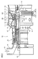
Figur 1 links ist ein Bauteil 1, 120, 130, 155 dargestellt.
Das Bauteil 1 weist ein Substrat 4 auf, das insbesondere bei Turbinenschaufeln 120, 130 aus einer nickel- oder kobaltbasierten Superlegierung besteht. - Auf das Substrat 4 werden ein oder mehrere Beschichtungen 7 aufgebracht. Dies können metallische Schutzbeschichtungen 7 (MCrAlX) und/oder keramische Schichten 7 sein.
- Die Beschichtung 7, die insbesondere die äußerste Schicht des Schichtsystems darstellt, weist an einer Stelle eine lokale Unregelmäßigkeit 10 oder eine schwer zugängliche Stelle 10 auf. Dies kann vorzugsweise eine nicht erreichte erforderliche Schichtdicke oder vorzugsweise Stellen an deren keine Beschichtung vorhanden ist.
- Die Schicht 7 ist im ersten Schritt durch ein erstes Beschichtungsverfahren, insbesondere ein thermisches Spritzverfahren wie vorzugsweise Plasmaspritzen, HVOF oder Kaltgasspritzen aufgebracht worden.
Das erste Beschichtungsverfahren stellt vorzugsweise ein automatisiertes oder halbautomatisiertes Beschichtungsverfahren in einer Anlage dar, bei dem das Substrat 4 in einer Beschichtungsapperation eingebaut wird und dann nach einem ausgewählten Programm beschichtet wird. - In einem zweiten Verfahrensschritt wird mittels eines zweiten Beschichtungsverfahrens auf die lokale Stelle 10 zusätzlich Material 13 aufgebracht, das die lokale Unregelmäßigkeit 10 beseitigt.
- Die Stelle 10 ist nie die Fläche, die durch das erste Beschichtungsverfahren beschichtet wurde. Das zweite Beschichtungsverfahren ist im Gegensatz zum ersten Beschichtungsverfahren ein lokales Beschichtungsverfahren zur Reparatur. Vorzugsweise wird lokal Keramik auf Keramik aufgebracht, also wird Beschichtungsmaterial im zweiten Beschichtungsverfahren auf eine Schicht aufgebracht, die bereits durch das erste Beschichtungsverfahren erzeugt wurde.
- Das Material 13 wird durch ein zweites von dem ersten verschiedenen, insbesondere nicht-thermischen Beschichtungsverfahren aufgebracht. Das zweite Verfahren ist kein Plasmaspritzen, kein CVD, kein PVD, kein HVOF und kein Kaltgasspritzen.
- Das zweite Beschichtungsverfahren stellt ein Schlickerauftrag oder Schlickeraufspritzen dar.
Der Schlicker weist für das Pulver (Beschichtungsmaterial) vorzugsweise die gleiche chemische Zusammensetzung auf wie das Material, das auch beim ersten Beschichten verwendet wurde. Insbesondere wird auch die gleiche Korngrößenverteilung verwendet wie beim ersten Beschichten. Ganz vorzugsweise wird eine etwas kleinere Korngrößenverteilung verwendet (d.h. die mittlere Korngröße ist messbar kleiner). - Der Begriff "nicht-thermisch" bezieht sich auf die Temperatur beim Auftragen von Material auf ein Substrat, d.h. ob das Material während des Aufbringens erwärmt wird (≥ 100°C, insbesondere > 300°C) und nicht auf nachfolgende Schritte nach dem Auftrag wie z.B. ein Entbinderungsschritt oder ein Sintern.
- Das zweite Beschichtungsverfahren ist vorzugsweise ein manuelles Beschichtungsverfahren (Pinseln, Gießen, Aufstreichen, Aufspritzen, ...) .
Ein Schlicker ist ein Gemisch aus einem Pulver und zumindest einer Flüssigkeit (Lösungsmittel) und ggf. eines Binders. - Der vorhandene Binder wird im Einsatz entbindert und/oder verdichtet und gleicht die Ungleichmäßigkeit 10 aus oder beseitigt sie vollständig.
- Die Beseitigung der Unregelmäßigkeit 10 erfolgt durch das Verfahren sehr schnell und einfach gegenüber dem aufwändigen lokalen Beschichten in einer Beschichtungsapparatur. Sie kann daher auch angewandt werden, wenn Fehler nach Auslieferung auffällig werden, insbesondere auch vor Ort beim Kunden.
- Die
Figur 2 zeigt beispielhaft eine Gasturbine 100 in einem Längsteilschnitt.
Die Gasturbine 100 weist im Inneren einen um eine Rotationsachse 102 drehgelagerten Rotor 103 mit einer Welle auf, der auch als Turbinenläufer bezeichnet wird.
Entlang des Rotors 103 folgen aufeinander ein Ansauggehäuse 104, ein Verdichter 105, eine beispielsweise torusartige Brennkammer 110, insbesondere Ringbrennkammer, mit mehreren koaxial angeordneten Brennern 107, eine Turbine 108 und das Abgasgehäuse 109.
Die Ringbrennkammer 110 kommuniziert mit einem beispielsweise ringförmigen Heißgaskanal 111. Dort bilden beispielsweise vier hintereinander geschaltete Turbinenstufen 112 die Turbine 108.
Jede Turbinenstufe 112 ist beispielsweise aus zwei Schaufelringen gebildet. In Strömungsrichtung eines Arbeitsmediums 113 gesehen folgt im Heißgaskanal 111 einer Leitschaufelreihe 115 eine aus Laufschaufeln 120 gebildete Reihe 125. - Die Leitschaufeln 130 sind dabei an einem Innengehäuse 138 eines Stators 143 befestigt, wohingegen die Laufschaufeln 120 einer Reihe 125 beispielsweise mittels einer Turbinenscheibe 133 am Rotor 103 angebracht sind.
An dem Rotor 103 angekoppelt ist ein Generator oder eine Arbeitsmaschine (nicht dargestellt). - Während des Betriebes der Gasturbine 100 wird vom Verdichter 105 durch das Ansauggehäuse 104 Luft 135 angesaugt und verdichtet. Die am turbinenseitigen Ende des Verdichters 105 bereitgestellte verdichtete Luft wird zu den Brennern 107 geführt und dort mit einem Brennmittel vermischt. Das Gemisch wird dann unter Bildung des Arbeitsmediums 113 in der Brennkammer 110 verbrannt. Von dort aus strömt das Arbeitsmedium 113 entlang des Heißgaskanals 111 vorbei an den Leitschaufeln 130 und den Laufschaufeln 120. An den Laufschaufeln 120 entspannt sich das Arbeitsmedium 113 impulsübertragend, so dass die Laufschaufeln 120 den Rotor 103 antreiben und dieser die an ihn angekoppelte Arbeitsmaschine.
- Die dem heißen Arbeitsmedium 113 ausgesetzten Bauteile unterliegen während des Betriebes der Gasturbine 100 thermischen Belastungen. Die Leitschaufeln 130 und Laufschaufeln 120 der in Strömungsrichtung des Arbeitsmediums 113 gesehen ersten Turbinenstufe 112 werden neben den die Ringbrennkammer 110 auskleidenden Hitzeschildelementen am meisten thermisch belastet.
Um den dort herrschenden Temperaturen standzuhalten, können diese mittels eines Kühlmittels gekühlt werden.
Ebenso können Substrate der Bauteile eine gerichtete Struktur aufweisen, d.h. sie sind einkristallin (SX-Struktur) oder weisen nur längsgerichtete Körner auf (DS-Struktur).
Als Material für die Bauteile, insbesondere für die Turbinenschaufel 120, 130 und Bauteile der Brennkammer 110 werden beispielsweise eisen-, nickel- oder kobaltbasierte Superlegierungen verwendet.
Solche Superlegierungen sind beispielsweise aus derEP 1 204 776 B1 ,EP 1 306 454 ,EP 1 319 729 A1 ,WO 99/67435 WO 00/44949 - Die Leitschaufel 130 weist einen dem Innengehäuse 138 der Turbine 108 zugewandten Leitschaufelfuß (hier nicht dargestellt) und einen dem Leitschaufelfuß gegenüberliegenden Leitschaufelkopf auf. Der Leitschaufelkopf ist dem Rotor 103 zugewandt und an einem Befestigungsring 140 des Stators 143 festgelegt.
- Die
Figur 3 zeigt in perspektivischer Ansicht eine Laufschaufel 120 oder Leitschaufel 130 einer Strömungsmaschine, die sich entlang einer Längsachse 121 erstreckt. - Die Strömungsmaschine kann eine Gasturbine eines Flugzeugs oder eines Kraftwerks zur Elektrizitätserzeugung, eine Dampfturbine oder ein Kompressor sein.
- Die Schaufel 120, 130 weist entlang der Längsachse 121 aufeinander folgend einen Befestigungsbereich 400, eine daran angrenzende Schaufelplattform 403 sowie ein Schaufelblatt 406 und eine Schaufelspitze 415 auf.
Als Leitschaufel 130 kann die Schaufel 130 an ihrer Schaufelspitze 415 eine weitere Plattform aufweisen (nicht dargestellt). - Im Befestigungsbereich 400 ist ein Schaufelfuß 183 gebildet, der zur Befestigung der Laufschaufeln 120, 130 an einer Welle oder einer Scheibe dient (nicht dargestellt).
Der Schaufelfuß 183 ist beispielsweise als Hammerkopf ausgestaltet. Andere Ausgestaltungen als Tannenbaum- oder Schwalbenschwanzfuß sind möglich.
Die Schaufel 120, 130 weist für ein Medium, das an dem Schaufelblatt 406 vorbeiströmt, eine Anströmkante 409 und eine Abströmkante 412 auf. - Bei herkömmlichen Schaufeln 120, 130 werden in allen Bereichen 400, 403, 406 der Schaufel 120, 130 beispielsweise massive metallische Werkstoffe, insbesondere Superlegierungen verwendet.
Solche Superlegierungen sind beispielsweise aus derEP 1 204 776 B1 ,EP 1 306 454 ,EP 1 319 729 A1 ,WO 99/67435 WO 00/44949
Die Schaufel 120, 130 kann hierbei durch ein Gussverfahren, auch mittels gerichteter Erstarrung, durch ein Schmiedeverfahren, durch ein Fräsverfahren oder Kombinationen daraus gefertigt sein. - Werkstücke mit einkristalliner Struktur oder Strukturen werden als Bauteile für Maschinen eingesetzt, die im Betrieb hohen mechanischen, thermischen und/oder chemischen Belastungen ausgesetzt sind.
Die Fertigung von derartigen einkristallinen Werkstücken erfolgt z.B. durch gerichtetes Erstarren aus der Schmelze. Es handelt sich dabei um Gießverfahren, bei denen die flüssige metallische Legierung zur einkristallinen Struktur, d.h. zum einkristallinen Werkstück, oder gerichtet erstarrt.
Dabei werden dendritische Kristalle entlang dem Wärmefluss ausgerichtet und bilden entweder eine stängelkristalline Kornstruktur (kolumnar, d.h. Körner, die über die ganze Länge des Werkstückes verlaufen und hier, dem allgemeinen Sprachgebrauch nach, als gerichtet erstarrt bezeichnet werden) oder eine einkristalline Struktur, d.h. das ganze Werkstück besteht aus einem einzigen Kristall. In diesen Verfahren muss man den Übergang zur globulitischen (polykristallinen) Erstarrung meiden, da sich durch ungerichtetes Wachstum notwendigerweise transversale und longitudinale Korngrenzen ausbilden, welche die guten Eigenschaften des gerichtet erstarrten oder einkristallinen Bauteiles zunichte machen.
Ist allgemein von gerichtet erstarrten Gefügen die Rede, so sind damit sowohl Einkristalle gemeint, die keine Korngrenzen oder höchstens Kleinwinkelkorngrenzen aufweisen, als auch Stängelkristallstrukturen, die wohl in longitudinaler Richtung verlaufende Korngrenzen, aber keine transversalen Korngrenzen aufweisen. Bei diesen zweitgenannten kristallinen Strukturen spricht man auch von gerichtet erstarrten Gefügen (directionally solidified structures).
Solche Verfahren sind aus derUS-PS 6,024,792 und derEP 0 892 090 A1 bekannt. - Ebenso können die Schaufeln 120, 130 Beschichtungen gegen Korrosion oder Oxidation aufweisen, z. B. (MCrAlX; M ist zumindest ein Element der Gruppe Eisen (Fe), Kobalt (Co), Nickel (Ni), X ist ein Aktivelement und steht für Yttrium (Y) und/oder Silizium und/oder zumindest ein Element der Seltenen Erden, bzw. Hafnium (Hf)). Solche Legierungen sind bekannt aus der
EP 0 486 489 B1 ,EP 0 786 017 B1 ,EP 0 412 397 B1 oderEP 1 306 454 A1 .
Die Dichte liegt vorzugsweise bei 95% der theoretischen Dichte.
Auf der MCrAlX-Schicht (als Zwischenschicht oder als äußerste Schicht) bildet sich eine schützende Aluminiumoxidschicht (TGO = thermal grown oxide layer). - Vorzugsweise weist die Schichtzusammensetzung Co-30Ni-28Cr-8A1-0,6Y-0,7Si oder Co-28Ni-24Cr-10Al-0,6Y auf. Neben diesen kobaltbasierten Schutzbeschichtungen werden auch vorzugsweise nickelbasierte Schutzschichten verwendet wie Ni-10Cr-12Al-0,6Y-3Re oder Ni-12Co-21Cr-11Al-0,4Y-2Re oder Ni-25Co-17Cr-10Al-0,4Y-1,5Re.
- Auf der MCrAlX kann noch eine Wärmedämmschicht vorhanden sein, die vorzugsweise die äußerste Schicht ist, und besteht beispielsweise aus ZrO2, Y2O3-ZrO2, d.h. sie ist nicht, teilweise oder vollständig stabilisiert durch Yttriumoxid und/oder Kalziumoxid und/oder Magnesiumoxid.
Die Wärmedämmschicht bedeckt die gesamte MCrAlX-Schicht. Durch geeignete Beschichtungsverfahren wie z.B. Elektronenstrahlverdampfen (EB-PVD) werden stängelförmige Körner in der Wärmedämmschicht erzeugt.
Andere Beschichtungsverfahren sind denkbar, z.B. atmosphärisches Plasmaspritzen (APS), LPPS, VPS oder CVD. Die Wärmedämmschicht kann poröse, mikro- oder makrorissbehaftete Körner zur besseren Thermoschockbeständigkeit aufweisen. Die Wärmedämmschicht ist also vorzugsweise poröser als die MCrAlX-Schicht. - Die Schaufel 120, 130 kann hohl oder massiv ausgeführt sein. Wenn die Schaufel 120, 130 gekühlt werden soll, ist sie hohl und weist ggf. noch Filmkühllöcher 418 (gestrichelt angedeutet) auf.
- Die
Figur 4 zeigt eine Brennkammer 110 der Gasturbine 100. Die Brennkammer 110 ist beispielsweise als so genannte Ringbrennkammer ausgestaltet, bei der eine Vielzahl von in Umfangsrichtung um eine Rotationsachse 102 herum angeordneten Brennern 107 in einen gemeinsamen Brennkammerraum 154 münden, die Flammen 156 erzeugen. Dazu ist die Brennkammer 110 in ihrer Gesamtheit als ringförmige Struktur ausgestaltet, die um die Rotationsachse 102 herum positioniert ist. - Zur Erzielung eines vergleichsweise hohen Wirkungsgrades ist die Brennkammer 110 für eine vergleichsweise hohe Temperatur des Arbeitsmediums M von etwa 1000°C bis 1600°C ausgelegt. Um auch bei diesen, für die Materialien ungünstigen Betriebsparametern eine vergleichsweise lange Betriebsdauer zu ermöglichen, ist die Brennkammerwand 153 auf ihrer dem Arbeitsmedium M zugewandten Seite mit einer aus Hitzeschildelementen 155 gebildeten Innenauskleidung versehen.
- Aufgrund der hohen Temperaturen im Inneren der Brennkammer 110 kann zudem für die Hitzeschildelemente 155 bzw. für deren Halteelemente ein Kühlsystem vorgesehen sein. Die Hitzeschildelemente 155 sind dann beispielsweise hohl und weisen ggf. noch in den Brennkammerraum 154 mündende Kühllöcher (nicht dargestellt) auf.
- Jedes Hitzeschildelement 155 aus einer Legierung ist arbeitsmediumsseitig mit einer besonders hitzebeständigen Schutzschicht (MCrAlX-Schicht und/oder keramische Beschichtung) ausgestattet oder ist aus hochtemperaturbeständigem Material (massive keramische Steine) gefertigt.
Diese Schutzschichten können ähnlich der Turbinenschaufeln sein, also bedeutet beispielsweise MCrAlX: M ist zumindest ein Element der Gruppe Eisen (Fe), Kobalt (Co), Nickel (Ni), X ist ein Aktivelement und steht für Yttrium (Y) und/oder Silizium und/oder zumindest ein Element der Seltenen Erden, bzw. Hafnium (Hf). Solche Legierungen sind bekannt aus derEP 0 486 489 B1 ,EP 0 786 017 B1 ,EP 0 412 397 B1 oderEP 1 306 454 A1 . - Auf der MCrAlX kann noch eine beispielsweise keramische Wärmedämmschicht vorhanden sein und besteht beispielsweise aus ZrO2, Y2O3-ZrO2, d.h. sie ist nicht, teilweise oder vollständig stabilisiert durch Yttriumoxid und/oder Kalziumoxid und/oder Magnesiumoxid etc..
Durch geeignete Beschichtungsverfahren wie z.B. Elektronenstrahlverdampfen (EB-PVD) werden stängelförmige Körner in der Wärmedämmschicht erzeugt.
Andere Beschichtungsverfahren sind denkbar, z.B. atmosphärisches Plasmaspritzen (APS), LPPS, VPS oder CVD. Die Wärmedämmschicht kann poröse, mikro- oder makrorissbehaftete Körner zur besseren Thermoschockbeständigkeit aufweisen. - Wiederaufarbeitung (Refurbishment) bedeutet, dass Turbinenschaufeln 120, 130, Hitzeschildelemente und andere Heißgaskomponenten 155 nach ihrem Einsatz gegebenenfalls von Schutzschichten befreit werden müssen (z.B. durch Sandstrahlen). Danach erfolgt eine Entfernung der Korrosions- und/oder Oxidationsschichten bzw. -produkte. Gegebenenfalls werden auch noch Risse in der Turbinenschaufel 120, 130 oder dem Hitzeschildelement 155 repariert. Danach erfolgt eine Wiederbeschichtung der Turbinenschaufeln 120, 130, Hitzeschildelemente 155 und ein erneuter Einsatz der Turbinenschaufeln 120, 130 oder der Hitzeschildelemente 155.
Claims (10)
- Verfahren zum Beschichten eines Substrats (4) eines Bauteils (1, 120, 130, 155),
insbesondere zur Reparatur
bei dem im ersten Schritt
ein erstes Beschichtungsverfahren angewendet wird, insbesondere ein Spritzverfahren,
ganz insbesondere ein thermisches Spritzverfahren,
um eine Schicht (7) zu erzeugen,
die (7) jedoch mindestens eine lokale Unregelmäßigkeit (10) aufweist,
dadurch gekennzeichnet, dass
die zumindest eine lokale Unregelmäßigkeit (10) durch ein zweites von dem ersten Beschichtungsverfahren verschiedenen Beschichtungsverfahren beseitigt wird,
bei dem das zweite Beschichtungsverfahren oder das nichtthermische Spritzverfahren ein Schlickerauftrag oder Schlickeraufspritzen darstellt,
bei dem ein Binder im Schlicker verwendet wird,
wobei der vorhandene Binder im Einsatz entbindert und/oder verdichtet wird. - Verfahren nach Anspruch 1,
bei dem das erste Beschichtungsverfahren ein thermisches Spritzverfahren darstellt. - Verfahren nach Anspruch 1,
bei dem das zweite Beschichtungsverfahren ein nicht-thermisches Beschichtungsverfahren darstellt. - Verfahren nach Anspruch 1, 2, 3 oder 4,
bei dem die Schicht (7) eine keramische Schicht darstellt. - Verfahren nach Anspruch 1 oder 2,
bei dem das erste Beschichtungsverfahren ein automatisches oder halbautomatisches Beschichtungsverfahren darstellt. - Verfahren nach Anspruch 1, 3, 4 oder 6,
bei dem das zweite Beschichtungsverfahren ein manuelles Verfahren darstellt. - Verfahren nach Anspruch 1, 2 oder 6,
bei dem das erste Beschichtungsverfahren oder das thermische Spritzverfahren ausgewählt wird aus Plasmaspritzen, HVOF oder Kaltgasspritzen. - Verfahren nach Anspruch 1, 2, 3 oder 4,
bei dem beim ersten und zweiten Verfahren das gleiche Beschichtungsmaterial verwendet wird. - Verfahren nach einem oder mehreren der vorherigen Ansprüche,
bei dem durch das zweite Beschichtungsverfahren Beschichtungsmaterial auf eine Schicht, die durch das erste Beschichtungsverfahren hergestellt wurde,
aufgebracht wird. - Verfahren nach Anspruch 6, 7, 8 oder 9,
bei dem beim zweiten Beschichtungsverfahren Beschichtungsmaterial aufgesprüht wird.
Priority Applications (1)
| Application Number | Priority Date | Filing Date | Title |
|---|---|---|---|
| EP10700522.5A EP2391744B1 (de) | 2009-01-28 | 2010-01-08 | Beschichtung mit thermischen und nicht-thermischen beschichtungsverfahren |
Applications Claiming Priority (3)
| Application Number | Priority Date | Filing Date | Title |
|---|---|---|---|
| EP09001190A EP2224039A1 (de) | 2009-01-28 | 2009-01-28 | Beschichtung mit thermischen und nicht-thermischen Beschichtungsverfahren |
| PCT/EP2010/050126 WO2010086202A2 (de) | 2009-01-28 | 2010-01-08 | Beschichtung mit thermischen und nicht-thermischen beschichtungsverfahren |
| EP10700522.5A EP2391744B1 (de) | 2009-01-28 | 2010-01-08 | Beschichtung mit thermischen und nicht-thermischen beschichtungsverfahren |
Publications (2)
| Publication Number | Publication Date |
|---|---|
| EP2391744A2 EP2391744A2 (de) | 2011-12-07 |
| EP2391744B1 true EP2391744B1 (de) | 2014-10-01 |
Family
ID=40651298
Family Applications (2)
| Application Number | Title | Priority Date | Filing Date |
|---|---|---|---|
| EP09001190A Ceased EP2224039A1 (de) | 2009-01-28 | 2009-01-28 | Beschichtung mit thermischen und nicht-thermischen Beschichtungsverfahren |
| EP10700522.5A Not-in-force EP2391744B1 (de) | 2009-01-28 | 2010-01-08 | Beschichtung mit thermischen und nicht-thermischen beschichtungsverfahren |
Family Applications Before (1)
| Application Number | Title | Priority Date | Filing Date |
|---|---|---|---|
| EP09001190A Ceased EP2224039A1 (de) | 2009-01-28 | 2009-01-28 | Beschichtung mit thermischen und nicht-thermischen Beschichtungsverfahren |
Country Status (3)
| Country | Link |
|---|---|
| US (1) | US20120027931A1 (de) |
| EP (2) | EP2224039A1 (de) |
| WO (1) | WO2010086202A2 (de) |
Cited By (2)
| Publication number | Priority date | Publication date | Assignee | Title |
|---|---|---|---|---|
| DE102014222686A1 (de) * | 2014-11-06 | 2016-05-12 | Siemens Aktiengesellschaft | Doppellagige Wärmedämmschicht durch unterschiedliche Beschichtungsverfahren |
| WO2018024759A1 (de) | 2016-08-02 | 2018-02-08 | Siemens Aktiengesellschaft | Verfahren zur herstellung einer kanalstruktur und komponente |
Families Citing this family (4)
| Publication number | Priority date | Publication date | Assignee | Title |
|---|---|---|---|---|
| EP2492443A1 (de) * | 2011-02-22 | 2012-08-29 | Siemens Aktiengesellschaft | Verfahren zur Herstellung einer Schutzschicht für eine Laufschaufel |
| EP2644824A1 (de) * | 2012-03-28 | 2013-10-02 | Siemens Aktiengesellschaft | Verfahren zur Herstellung und Wiederherstellung von keramischen Wärmedämmschichten in Gasturbinen sowie dazugehörige Gasturbine |
| KR20150060960A (ko) * | 2012-10-05 | 2015-06-03 | 지멘스 악티엔게젤샤프트 | 가스 터빈 블레이드 처리 방법 및 상기 블레이드를 포함한 가스 터빈 |
| CN105239060B (zh) * | 2015-11-06 | 2018-08-07 | 武汉理工大学 | 一种适用于太阳能选择性吸收的热喷涂涂层减反层及其制备方法 |
Family Cites Families (12)
| Publication number | Priority date | Publication date | Assignee | Title |
|---|---|---|---|---|
| DE58908611D1 (de) | 1989-08-10 | 1994-12-08 | Siemens Ag | Hochtemperaturfeste korrosionsschutzbeschichtung, insbesondere für gasturbinenbauteile. |
| DE3926479A1 (de) | 1989-08-10 | 1991-02-14 | Siemens Ag | Rheniumhaltige schutzbeschichtung, mit grosser korrosions- und/oder oxidationsbestaendigkeit |
| WO1996012049A1 (de) | 1994-10-14 | 1996-04-25 | Siemens Aktiengesellschaft | Schutzschicht zum schutz eines bauteils gegen korrosion, oxidation und thermische überbeanspruchung sowie verfahren zu ihrer herstellung |
| EP0861927A1 (de) | 1997-02-24 | 1998-09-02 | Sulzer Innotec Ag | Verfahren zum Herstellen von einkristallinen Strukturen |
| EP0892090B1 (de) | 1997-02-24 | 2008-04-23 | Sulzer Innotec Ag | Verfahren zum Herstellen von einkristallinen Strukturen |
| EP1306454B1 (de) | 2001-10-24 | 2004-10-06 | Siemens Aktiengesellschaft | Rhenium enthaltende Schutzschicht zum Schutz eines Bauteils gegen Korrosion und Oxidation bei hohen Temperaturen |
| WO1999067435A1 (en) | 1998-06-23 | 1999-12-29 | Siemens Aktiengesellschaft | Directionally solidified casting with improved transverse stress rupture strength |
| US6231692B1 (en) | 1999-01-28 | 2001-05-15 | Howmet Research Corporation | Nickel base superalloy with improved machinability and method of making thereof |
| DE50006694D1 (de) | 1999-07-29 | 2004-07-08 | Siemens Ag | Hochtemperaturbeständiges bauteil und verfahren zur herstellung des hochtemperaturbeständigen bauteils |
| US6294261B1 (en) * | 1999-10-01 | 2001-09-25 | General Electric Company | Method for smoothing the surface of a protective coating |
| DE50112339D1 (de) | 2001-12-13 | 2007-05-24 | Siemens Ag | Hochtemperaturbeständiges Bauteil aus einkristalliner oder polykristalliner Nickel-Basis-Superlegierung |
| US7368164B2 (en) * | 2004-06-18 | 2008-05-06 | General Electric Company | Smooth outer coating for combustor components and coating method therefor |
-
2009
- 2009-01-28 EP EP09001190A patent/EP2224039A1/de not_active Ceased
-
2010
- 2010-01-08 WO PCT/EP2010/050126 patent/WO2010086202A2/de not_active Ceased
- 2010-01-08 US US13/146,737 patent/US20120027931A1/en not_active Abandoned
- 2010-01-08 EP EP10700522.5A patent/EP2391744B1/de not_active Not-in-force
Cited By (4)
| Publication number | Priority date | Publication date | Assignee | Title |
|---|---|---|---|---|
| DE102014222686A1 (de) * | 2014-11-06 | 2016-05-12 | Siemens Aktiengesellschaft | Doppellagige Wärmedämmschicht durch unterschiedliche Beschichtungsverfahren |
| WO2018024759A1 (de) | 2016-08-02 | 2018-02-08 | Siemens Aktiengesellschaft | Verfahren zur herstellung einer kanalstruktur und komponente |
| DE102016214208A1 (de) | 2016-08-02 | 2018-02-08 | Siemens Aktiengesellschaft | Verfahren zur Herstellung einer Kanalstruktur und Komponente |
| DE102016214208B4 (de) | 2016-08-02 | 2018-03-29 | Siemens Aktiengesellschaft | Verfahren zur Herstellung einer Kanalstruktur und Komponente |
Also Published As
| Publication number | Publication date |
|---|---|
| EP2391744A2 (de) | 2011-12-07 |
| US20120027931A1 (en) | 2012-02-02 |
| WO2010086202A3 (de) | 2011-12-01 |
| WO2010086202A2 (de) | 2010-08-05 |
| EP2224039A1 (de) | 2010-09-01 |
Similar Documents
| Publication | Publication Date | Title |
|---|---|---|
| EP2436798B1 (de) | Maskierungsmaterial, Maskierungsschicht und Verfahren zum Maskieren eines Substrats | |
| WO2010112553A2 (de) | Verfahren beim schweissen und bauteil | |
| EP2547488B1 (de) | Verfahren zum wiederaufarbeiten einer turbinenschaufel mit wenigstens einer plattform | |
| EP1952931A1 (de) | Mechtrode mit Pulverzufuhr und Verfahren zur Benutzung dieser Mechtrode | |
| EP2407579A1 (de) | Poröses keramisches Schichtsystem | |
| EP2907888A1 (de) | Verdichterschaufel mit erosionsbeständiger Hartstoffbeschichtung | |
| EP2373824B1 (de) | Verfahren zum beschichten eines bauteils mit filmkühllöchern, und bauteil | |
| WO2010089183A1 (de) | Turbinenbauteil mit leicht entfernbarer schutzschicht, satz von turbinenbauteilen, eine turbine und ein verfahren zum schützen eines turbinenbauteils | |
| EP2312267A1 (de) | Verfahren zur Schichtdickenmessung mittels Lasertriangulation und Vorrichtung | |
| EP2186594A1 (de) | Verfahren und Vorrichtung zur Vorwärmung beim Schweißen unter Verwendung eines zweiten Laserstrahles | |
| EP2224039A1 (de) | Beschichtung mit thermischen und nicht-thermischen Beschichtungsverfahren | |
| WO2009065753A1 (de) | Verfahren zum löten weiter spalte | |
| WO2009118313A2 (de) | Bauteil mit sich überlappenden schweissnähten und ein verfahren zur herstellung | |
| EP2226149A1 (de) | Zweischritt-Schweissverfahren | |
| WO2011107167A1 (de) | Keramisches wärmedämmschichtsystem mit modifizierter anbindungsschicht | |
| EP2353725A1 (de) | Spritzdüse und Verfahren zum atmosphärischen Spritzen, Vorrichtung zum Beschichten und beschichtetes Bauteil | |
| EP2241397A1 (de) | Belotung von Löchern, Verfahren zum Beschichten und Lötgutstäbchen | |
| EP2584067A1 (de) | Bauteil mit Graphen und Verfahren zur Herstellung von Bauteilen mit Graphen | |
| EP2583784A1 (de) | Vorbereitung einer Schweißstelle vor dem Schweißen und Bauteil | |
| EP2631321A1 (de) | Keramisches Wärmedämmschichtsystem mit äußerer aluminiumreicher Schicht und Verfahren | |
| WO2009053154A1 (de) | Verfahren zur entfernung einer metallischen schicht mittels fic in einem zwischenschritt | |
| EP2597259A1 (de) | Modifizierte Oberfläche um ein Loch | |
| WO2018114766A1 (de) | Verfahren zur fügung von heissgaskomponenten-segmenten durch löten und entsprechende heissgaskomponente | |
| EP2196555A1 (de) | Pulvermischung aus Keramik und Glas, Bauteil mit Maskierung und Verfahren zur Anwendung | |
| EP1797985A1 (de) | Schweissverfahren und Schweissvorrichtung |
Legal Events
| Date | Code | Title | Description |
|---|---|---|---|
| PUAI | Public reference made under article 153(3) epc to a published international application that has entered the european phase |
Free format text: ORIGINAL CODE: 0009012 |
|
| 17P | Request for examination filed |
Effective date: 20110629 |
|
| AK | Designated contracting states |
Kind code of ref document: A2 Designated state(s): AT BE BG CH CY CZ DE DK EE ES FI FR GB GR HR HU IE IS IT LI LT LU LV MC MK MT NL NO PL PT RO SE SI SK SM TR |
|
| R17D | Deferred search report published (corrected) |
Effective date: 20111201 |
|
| DAX | Request for extension of the european patent (deleted) | ||
| 17Q | First examination report despatched |
Effective date: 20130215 |
|
| RAP1 | Party data changed (applicant data changed or rights of an application transferred) |
Owner name: SIEMENS AKTIENGESELLSCHAFT |
|
| GRAP | Despatch of communication of intention to grant a patent |
Free format text: ORIGINAL CODE: EPIDOSNIGR1 |
|
| INTG | Intention to grant announced |
Effective date: 20140422 |
|
| GRAS | Grant fee paid |
Free format text: ORIGINAL CODE: EPIDOSNIGR3 |
|
| GRAA | (expected) grant |
Free format text: ORIGINAL CODE: 0009210 |
|
| AK | Designated contracting states |
Kind code of ref document: B1 Designated state(s): AT BE BG CH CY CZ DE DK EE ES FI FR GB GR HR HU IE IS IT LI LT LU LV MC MK MT NL NO PL PT RO SE SI SK SM TR |
|
| REG | Reference to a national code |
Ref country code: GB Ref legal event code: FG4D Free format text: NOT ENGLISH |
|
| REG | Reference to a national code |
Ref country code: AT Ref legal event code: REF Ref document number: 689608 Country of ref document: AT Kind code of ref document: T Effective date: 20141015 Ref country code: CH Ref legal event code: EP |
|
| REG | Reference to a national code |
Ref country code: IE Ref legal event code: FG4D Free format text: LANGUAGE OF EP DOCUMENT: GERMAN |
|
| REG | Reference to a national code |
Ref country code: DE Ref legal event code: R096 Ref document number: 502010007979 Country of ref document: DE Effective date: 20141113 |
|
| REG | Reference to a national code |
Ref country code: NL Ref legal event code: T3 |
|
| REG | Reference to a national code |
Ref country code: LT Ref legal event code: MG4D |
|
| PG25 | Lapsed in a contracting state [announced via postgrant information from national office to epo] |
Ref country code: PT Free format text: LAPSE BECAUSE OF FAILURE TO SUBMIT A TRANSLATION OF THE DESCRIPTION OR TO PAY THE FEE WITHIN THE PRESCRIBED TIME-LIMIT Effective date: 20150202 Ref country code: LT Free format text: LAPSE BECAUSE OF FAILURE TO SUBMIT A TRANSLATION OF THE DESCRIPTION OR TO PAY THE FEE WITHIN THE PRESCRIBED TIME-LIMIT Effective date: 20141001 Ref country code: NO Free format text: LAPSE BECAUSE OF FAILURE TO SUBMIT A TRANSLATION OF THE DESCRIPTION OR TO PAY THE FEE WITHIN THE PRESCRIBED TIME-LIMIT Effective date: 20150101 Ref country code: IS Free format text: LAPSE BECAUSE OF FAILURE TO SUBMIT A TRANSLATION OF THE DESCRIPTION OR TO PAY THE FEE WITHIN THE PRESCRIBED TIME-LIMIT Effective date: 20150201 Ref country code: CZ Free format text: LAPSE BECAUSE OF FAILURE TO SUBMIT A TRANSLATION OF THE DESCRIPTION OR TO PAY THE FEE WITHIN THE PRESCRIBED TIME-LIMIT Effective date: 20141001 Ref country code: ES Free format text: LAPSE BECAUSE OF FAILURE TO SUBMIT A TRANSLATION OF THE DESCRIPTION OR TO PAY THE FEE WITHIN THE PRESCRIBED TIME-LIMIT Effective date: 20141001 Ref country code: FI Free format text: LAPSE BECAUSE OF FAILURE TO SUBMIT A TRANSLATION OF THE DESCRIPTION OR TO PAY THE FEE WITHIN THE PRESCRIBED TIME-LIMIT Effective date: 20141001 |
|
| PG25 | Lapsed in a contracting state [announced via postgrant information from national office to epo] |
Ref country code: CY Free format text: LAPSE BECAUSE OF FAILURE TO SUBMIT A TRANSLATION OF THE DESCRIPTION OR TO PAY THE FEE WITHIN THE PRESCRIBED TIME-LIMIT Effective date: 20141001 Ref country code: HR Free format text: LAPSE BECAUSE OF FAILURE TO SUBMIT A TRANSLATION OF THE DESCRIPTION OR TO PAY THE FEE WITHIN THE PRESCRIBED TIME-LIMIT Effective date: 20141001 Ref country code: GR Free format text: LAPSE BECAUSE OF FAILURE TO SUBMIT A TRANSLATION OF THE DESCRIPTION OR TO PAY THE FEE WITHIN THE PRESCRIBED TIME-LIMIT Effective date: 20150102 Ref country code: SE Free format text: LAPSE BECAUSE OF FAILURE TO SUBMIT A TRANSLATION OF THE DESCRIPTION OR TO PAY THE FEE WITHIN THE PRESCRIBED TIME-LIMIT Effective date: 20141001 Ref country code: LV Free format text: LAPSE BECAUSE OF FAILURE TO SUBMIT A TRANSLATION OF THE DESCRIPTION OR TO PAY THE FEE WITHIN THE PRESCRIBED TIME-LIMIT Effective date: 20141001 Ref country code: PL Free format text: LAPSE BECAUSE OF FAILURE TO SUBMIT A TRANSLATION OF THE DESCRIPTION OR TO PAY THE FEE WITHIN THE PRESCRIBED TIME-LIMIT Effective date: 20141001 |
|
| PG25 | Lapsed in a contracting state [announced via postgrant information from national office to epo] |
Ref country code: BE Free format text: LAPSE BECAUSE OF NON-PAYMENT OF DUE FEES Effective date: 20150131 |
|
| REG | Reference to a national code |
Ref country code: DE Ref legal event code: R097 Ref document number: 502010007979 Country of ref document: DE |
|
| PG25 | Lapsed in a contracting state [announced via postgrant information from national office to epo] |
Ref country code: EE Free format text: LAPSE BECAUSE OF FAILURE TO SUBMIT A TRANSLATION OF THE DESCRIPTION OR TO PAY THE FEE WITHIN THE PRESCRIBED TIME-LIMIT Effective date: 20141001 Ref country code: SK Free format text: LAPSE BECAUSE OF FAILURE TO SUBMIT A TRANSLATION OF THE DESCRIPTION OR TO PAY THE FEE WITHIN THE PRESCRIBED TIME-LIMIT Effective date: 20141001 Ref country code: RO Free format text: LAPSE BECAUSE OF FAILURE TO SUBMIT A TRANSLATION OF THE DESCRIPTION OR TO PAY THE FEE WITHIN THE PRESCRIBED TIME-LIMIT Effective date: 20141001 Ref country code: DK Free format text: LAPSE BECAUSE OF FAILURE TO SUBMIT A TRANSLATION OF THE DESCRIPTION OR TO PAY THE FEE WITHIN THE PRESCRIBED TIME-LIMIT Effective date: 20141001 |
|
| PLBE | No opposition filed within time limit |
Free format text: ORIGINAL CODE: 0009261 |
|
| STAA | Information on the status of an ep patent application or granted ep patent |
Free format text: STATUS: NO OPPOSITION FILED WITHIN TIME LIMIT |
|
| REG | Reference to a national code |
Ref country code: CH Ref legal event code: PL |
|
| PG25 | Lapsed in a contracting state [announced via postgrant information from national office to epo] |
Ref country code: LU Free format text: LAPSE BECAUSE OF FAILURE TO SUBMIT A TRANSLATION OF THE DESCRIPTION OR TO PAY THE FEE WITHIN THE PRESCRIBED TIME-LIMIT Effective date: 20150108 |
|
| 26N | No opposition filed |
Effective date: 20150702 |
|
| PG25 | Lapsed in a contracting state [announced via postgrant information from national office to epo] |
Ref country code: MC Free format text: LAPSE BECAUSE OF FAILURE TO SUBMIT A TRANSLATION OF THE DESCRIPTION OR TO PAY THE FEE WITHIN THE PRESCRIBED TIME-LIMIT Effective date: 20141001 |
|
| PG25 | Lapsed in a contracting state [announced via postgrant information from national office to epo] |
Ref country code: CH Free format text: LAPSE BECAUSE OF NON-PAYMENT OF DUE FEES Effective date: 20150131 Ref country code: LI Free format text: LAPSE BECAUSE OF NON-PAYMENT OF DUE FEES Effective date: 20150131 |
|
| REG | Reference to a national code |
Ref country code: FR Ref legal event code: ST Effective date: 20150930 |
|
| REG | Reference to a national code |
Ref country code: IE Ref legal event code: MM4A |
|
| PG25 | Lapsed in a contracting state [announced via postgrant information from national office to epo] |
Ref country code: FR Free format text: LAPSE BECAUSE OF NON-PAYMENT OF DUE FEES Effective date: 20150202 |
|
| PG25 | Lapsed in a contracting state [announced via postgrant information from national office to epo] |
Ref country code: IE Free format text: LAPSE BECAUSE OF NON-PAYMENT OF DUE FEES Effective date: 20150108 |
|
| PG25 | Lapsed in a contracting state [announced via postgrant information from national office to epo] |
Ref country code: SI Free format text: LAPSE BECAUSE OF FAILURE TO SUBMIT A TRANSLATION OF THE DESCRIPTION OR TO PAY THE FEE WITHIN THE PRESCRIBED TIME-LIMIT Effective date: 20141001 |
|
| REG | Reference to a national code |
Ref country code: AT Ref legal event code: MM01 Ref document number: 689608 Country of ref document: AT Kind code of ref document: T Effective date: 20150108 |
|
| PGFP | Annual fee paid to national office [announced via postgrant information from national office to epo] |
Ref country code: NL Payment date: 20160120 Year of fee payment: 7 |
|
| PGFP | Annual fee paid to national office [announced via postgrant information from national office to epo] |
Ref country code: DE Payment date: 20160321 Year of fee payment: 7 Ref country code: IT Payment date: 20160127 Year of fee payment: 7 |
|
| PG25 | Lapsed in a contracting state [announced via postgrant information from national office to epo] |
Ref country code: AT Free format text: LAPSE BECAUSE OF NON-PAYMENT OF DUE FEES Effective date: 20150108 |
|
| PGFP | Annual fee paid to national office [announced via postgrant information from national office to epo] |
Ref country code: GB Payment date: 20160111 Year of fee payment: 7 |
|
| PG25 | Lapsed in a contracting state [announced via postgrant information from national office to epo] |
Ref country code: MT Free format text: LAPSE BECAUSE OF FAILURE TO SUBMIT A TRANSLATION OF THE DESCRIPTION OR TO PAY THE FEE WITHIN THE PRESCRIBED TIME-LIMIT Effective date: 20141001 |
|
| PG25 | Lapsed in a contracting state [announced via postgrant information from national office to epo] |
Ref country code: HU Free format text: LAPSE BECAUSE OF FAILURE TO SUBMIT A TRANSLATION OF THE DESCRIPTION OR TO PAY THE FEE WITHIN THE PRESCRIBED TIME-LIMIT; INVALID AB INITIO Effective date: 20100108 Ref country code: SM Free format text: LAPSE BECAUSE OF FAILURE TO SUBMIT A TRANSLATION OF THE DESCRIPTION OR TO PAY THE FEE WITHIN THE PRESCRIBED TIME-LIMIT Effective date: 20141001 Ref country code: BG Free format text: LAPSE BECAUSE OF FAILURE TO SUBMIT A TRANSLATION OF THE DESCRIPTION OR TO PAY THE FEE WITHIN THE PRESCRIBED TIME-LIMIT Effective date: 20141001 |
|
| REG | Reference to a national code |
Ref country code: DE Ref legal event code: R119 Ref document number: 502010007979 Country of ref document: DE |
|
| PG25 | Lapsed in a contracting state [announced via postgrant information from national office to epo] |
Ref country code: TR Free format text: LAPSE BECAUSE OF FAILURE TO SUBMIT A TRANSLATION OF THE DESCRIPTION OR TO PAY THE FEE WITHIN THE PRESCRIBED TIME-LIMIT Effective date: 20141001 |
|
| REG | Reference to a national code |
Ref country code: NL Ref legal event code: MM Effective date: 20170201 |
|
| GBPC | Gb: european patent ceased through non-payment of renewal fee |
Effective date: 20170108 |
|
| PG25 | Lapsed in a contracting state [announced via postgrant information from national office to epo] |
Ref country code: NL Free format text: LAPSE BECAUSE OF NON-PAYMENT OF DUE FEES Effective date: 20170201 Ref country code: GB Free format text: LAPSE BECAUSE OF NON-PAYMENT OF DUE FEES Effective date: 20170108 Ref country code: DE Free format text: LAPSE BECAUSE OF NON-PAYMENT OF DUE FEES Effective date: 20170801 |
|
| PG25 | Lapsed in a contracting state [announced via postgrant information from national office to epo] |
Ref country code: IT Free format text: LAPSE BECAUSE OF NON-PAYMENT OF DUE FEES Effective date: 20170108 |
|
| PG25 | Lapsed in a contracting state [announced via postgrant information from national office to epo] |
Ref country code: MK Free format text: LAPSE BECAUSE OF FAILURE TO SUBMIT A TRANSLATION OF THE DESCRIPTION OR TO PAY THE FEE WITHIN THE PRESCRIBED TIME-LIMIT Effective date: 20141001 |