EP2391487B1 - Paper roll dispenser with sensor attached to manual actuator - Google Patents
Paper roll dispenser with sensor attached to manual actuator Download PDFInfo
- Publication number
- EP2391487B1 EP2391487B1 EP10732129.1A EP10732129A EP2391487B1 EP 2391487 B1 EP2391487 B1 EP 2391487B1 EP 10732129 A EP10732129 A EP 10732129A EP 2391487 B1 EP2391487 B1 EP 2391487B1
- Authority
- EP
- European Patent Office
- Prior art keywords
- sensor
- product
- recited
- drive roller
- advance assembly
- Prior art date
- Legal status (The legal status is an assumption and is not a legal conclusion. Google has not performed a legal analysis and makes no representation as to the accuracy of the status listed.)
- Not-in-force
Links
Images






Classifications
-
- A—HUMAN NECESSITIES
- A47—FURNITURE; DOMESTIC ARTICLES OR APPLIANCES; COFFEE MILLS; SPICE MILLS; SUCTION CLEANERS IN GENERAL
- A47K—SANITARY EQUIPMENT; ACCESSORIES THEREFOR, e.g. TOILET ACCESSORIES
- A47K10/00—Body-drying implements; Toilet paper; Holders therefor
- A47K10/24—Towel dispensers; Toilet paper dispensers
- A47K10/32—Dispensers for paper towels or toilet paper
- A47K10/34—Dispensers for paper towels or toilet paper dispensing from a web, e.g. with mechanical dispensing means
- A47K10/36—Dispensers for paper towels or toilet paper dispensing from a web, e.g. with mechanical dispensing means with mechanical dispensing, roll switching or cutting devices
- A47K10/3606—The cutting devices being motor driven
- A47K10/3625—The cutting devices being motor driven with electronic control means
-
- A—HUMAN NECESSITIES
- A47—FURNITURE; DOMESTIC ARTICLES OR APPLIANCES; COFFEE MILLS; SPICE MILLS; SUCTION CLEANERS IN GENERAL
- A47K—SANITARY EQUIPMENT; ACCESSORIES THEREFOR, e.g. TOILET ACCESSORIES
- A47K10/00—Body-drying implements; Toilet paper; Holders therefor
- A47K10/24—Towel dispensers; Toilet paper dispensers
- A47K10/32—Dispensers for paper towels or toilet paper
- A47K10/34—Dispensers for paper towels or toilet paper dispensing from a web, e.g. with mechanical dispensing means
- A47K10/36—Dispensers for paper towels or toilet paper dispensing from a web, e.g. with mechanical dispensing means with mechanical dispensing, roll switching or cutting devices
- A47K10/3606—The cutting devices being motor driven
- A47K10/3612—The cutting devices being motor driven with drive and pinch rollers
-
- A—HUMAN NECESSITIES
- A47—FURNITURE; DOMESTIC ARTICLES OR APPLIANCES; COFFEE MILLS; SPICE MILLS; SUCTION CLEANERS IN GENERAL
- A47K—SANITARY EQUIPMENT; ACCESSORIES THEREFOR, e.g. TOILET ACCESSORIES
- A47K10/00—Body-drying implements; Toilet paper; Holders therefor
- A47K10/24—Towel dispensers; Toilet paper dispensers
- A47K10/32—Dispensers for paper towels or toilet paper
- A47K10/34—Dispensers for paper towels or toilet paper dispensing from a web, e.g. with mechanical dispensing means
- A47K10/36—Dispensers for paper towels or toilet paper dispensing from a web, e.g. with mechanical dispensing means with mechanical dispensing, roll switching or cutting devices
- A47K10/3631—The cutting devices being driven manually
- A47K10/3637—The cutting devices being driven manually using a crank or handle
-
- A—HUMAN NECESSITIES
- A47—FURNITURE; DOMESTIC ARTICLES OR APPLIANCES; COFFEE MILLS; SPICE MILLS; SUCTION CLEANERS IN GENERAL
- A47K—SANITARY EQUIPMENT; ACCESSORIES THEREFOR, e.g. TOILET ACCESSORIES
- A47K10/00—Body-drying implements; Toilet paper; Holders therefor
- A47K10/24—Towel dispensers; Toilet paper dispensers
- A47K10/32—Dispensers for paper towels or toilet paper
- A47K10/34—Dispensers for paper towels or toilet paper dispensing from a web, e.g. with mechanical dispensing means
- A47K10/36—Dispensers for paper towels or toilet paper dispensing from a web, e.g. with mechanical dispensing means with mechanical dispensing, roll switching or cutting devices
- A47K2010/3668—Detection of the presence of a user
Definitions
- This disclosure relates generally to sheet product dispensers and particularly to away-from-home type paper towel dispensers with an automatic advance assembly and an interoperating manual advance assembly.
- folded paper towel dispensers contain a stack of folded individual paper towel segments that are dispensed through a slot.
- Other dispensers dispense paper towel segments from a tightly wound paper roll.
- Such dispensers can dispense paper towel segments from perforated or continuous paper rolls.
- Perforated roll dispensers contain a continuous paper roll with longitudinally spaced, transversely extending perforations that define individual paper towel segments. In continuous roll dispensers, a continuous paper roll may be cut into individual segments by a cutting device located in the dispenser.
- continuous roll dispensers which require a user to manually sever a paper segment from the continuous roll by pulling the paper against a serrated cutting blade. Such dispensers cannot control the length of the paper segment dispensed, and are thus susceptible to paper wastage.
- a portion control dispenser which automatically cuts the paper roll into paper towel segments as the paper is being dispensed from the dispenser.
- the paper roll is rotatably mounted inside the dispenser and a leading edge of the paper is fed through a cutting roller and out of the dispenser through a slot. The paper is advanced manually by a user operating a paper advance mechanism or pulling on the leading edge of the paper roll.
- the cutting roller rotates and a knife in the cutting roller extends radially outwards and punctures the paper, thereby severing a paper towel segment from the roll.
- the dispenser is designed to cut the paper into segments of defined length and only one at a time, thereby reducing paper wastage.
- the continuous roll dispenser can be a "hands-free" (touchless) type, i.e., designed to dispense paper towel segments without requiring the user to touch any part of the dispenser other than the leading edge of the paper roll. Such a design may be particularly desirable as the user is not exposed to germs or contaminants on other parts of the dispenser.
- Motorized hands-free dispensers typically have a proximity or motion sensor within the body of the cabinet that detects a user's hand or hand movement. When the sensor detects a user, a motor inside the dispenser is activated. The motor is coupled to the paper roll and advances a paper segment out of the dispenser. Examples of such motorized hands-free dispensers are disclosed in U.S. Pat. Nos. 5,772,291 , 6,412,679 , 6,695,246 , 6,892,620 , and 6,903,654 .
- US 2007-079684 A1 discloses a hybrid towel dispenser that is operable in an automatic dispensing mode and a manual dispensing mode.
- the dispenser comprises all of the features of the preamble of claim 1.
- the disclosed paper product dispenser provides an improved hands-free towel dispenser with the sensor positioned in a very intuitive location on the dispenser.
- a further objective of the disclosure is to provide a paper towel dispenser that can operate in both an automated dispensing mode and in a manual dispensing mode.
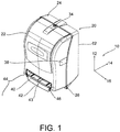
- axis system 10 is shown in Fig. 1 comprising a vertical axis 12, a transverse axis 14, and a lateral axis 16.
- a vertical axis 12 comprising a vertical axis 12, a transverse axis 14, and a lateral axis 16.
- a hands-free/manual hybrid dispenser 20 comprising a front cover 22 and a back cover 24.
- the front cover 22 in one embodiment is coupled to the back cover 24 at a lower vertical position by way of a hinge 26.
- a front cover 28 and a backside 30 are coupled by way of a hinge 32 along one lateral side.
- the upper vertical portion of the front cover 22 is secured to the back cover 24 by way of a latch 34.
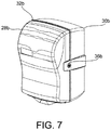
- the embodiment shown in Fig. 7 is coupled by way of a latch 36 on one lateral side.
- a view window 38 may be provided in one lateral side.
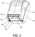
- a product outlet 40 is shown in the lowermost portion adjacent a manual actuator 42. When one of the dispensing systems disclosed herein is activated, a portion of the sheet product will exit through this product outlet 40 such that a user can grasp it and remove it.
- the novel feature of this design is the hybrid actuating mechanism comprising both an automatic dispensing system and a manual dispensing system.
- the dispenser is configured such that a user reaching toward the manual actuator 42 will activate an object sensor 43 having a field of view 44 projecting through the user engagement surface 46 of the manual actuator 42. In this way, before the user contacts the user engagement surface 46, the sensor should detect the proximity of the user and automatically dispense a portion of product, given that the automatic dispensing system is functioning properly. If the automatic dispensing system is not actuating properly, the user will continue to reach toward the manual actuator 42, contacting the user engagement surface 46 and thus putting pressure upon the manual actuator 40 to manually dispense a portion of product.
- the manual actuator 42 comprises a cover plate 48 which is attached to the user engagement surface 46, such that when the manual actuator 42 is engaged and pressed toward the back cover 24, the cover plate 48 repositions to an interior portion of the cabinet.
- the cover plate 48 repositions above a bottom plate 50 which is rigidly affixed, to or formed as a unitary structure with, the back cover 24.
- the object sensor 43 is disposed transversely behind the user engagement surface 46 such that the field of view 44 of the object sensor 43 projects through the user engagement surface 46.
- an indicator light 134 positioned behind the orifice 52 illuminates when the sensor 43 detects a user.
- the indicator light may comprise a colored light, for example green, which will blink when a user is detected.
- the indicator light may be used to indicate other conditions, such as a steady green light when the dispenser is ready to dispense more product or a red light which may blink to indicate a low battery condition.
- the object sensor 43 will tend to reposition relative to the casing along with the manual actuator 42 when the manual actuator 42 is engaged.
- a plurality of wires may be disposed vertically above the cover plate 48 within the dispenser 20 to protect them from wear and tear, and also to protect them from a negligent user.
- Figs. 1 and 2 The embodiment shown in Figs. 1 and 2 is also shown in Fig. 3 with the front cover 22 removed to more clearly show the internal workings thereof. Additionally, a sheet product holder, commonly known in the art, will be disposed in the upper portion 54 of the back cover 24. This sheet product holder is not shown to allow an easier understanding of the other workings of this dispenser. In one form, the sheet product holder is coupled via a plurality of extrusions 56 and 58 within the back cover 24. Also shown is a plurality of attachment openings 60 provided in the backside 62 of back cover 24, such that the towel dispenser 20 can be attached to a wall, door, or other surface.
- a power supply is utilized to provide power to the sensor 43, the motor 108, and any control or indicator circuitry.
- a battery tray 64 containing a plurality of batteries 66 may be included.
- a battery tray cover 68 is configured to be positioned adjacent the batteries 66 to complete the enclosure formed by the battery tray 64.
- the battery tray 64, batteries 66, and battery tray cover 68 interoperate as a DC power supply 70.
- This DC power supply 70 in one form is physically coupled to the product guide assembly 72.
- the product guide assembly 72 substantially functions to direct the product from the product roll, past a drive roller 74 and to exit through the product outlet 40, where it can be utilized.
- the product guide assembly 72 in one form removably couples to the back cover 24 and also serves as a mounting location for a power board 76.
- This power board 76 is shown in more detail in Fig. 9 and will be discussed in more detail herein.
- On one or both sides of the product guide assembly 72 is a drive mechanism 78.
- the drive mechanism 78 substantially comprises a plurality of gears, including a driver gear 80, an idler gear 82, and a driven gear 84. These gears 80, 82 and 84 generally comprise a gear assembly 86 which is mounted to a drive mechanism plate 88.
- the driver gear 80 further comprises a one-way bearing, such that manual activation of the dispenser will not harm the motor and associated mechanism and/or automatic activation will not engage the manual assembly.
- the drive mechanism plate 88 couples to the product guide assembly 72 and also forms an attachment for a roller assembly 90, including a pinch roller 136.
- the roller assembly 90 comprises a drive roller 74 having a right drive roller cap 92 and a left drive roller cap 94 removably affixed to either lateral end of the drive roller 74.
- the drive roller 74 is coupled to the drive mechanism 78 through a plurality of drive axles 96 and 98. These drive axles 96 and 98 are coupled to the driven gear 84 such that when the driven gear 84 rotates, force is translated to the drive roller 74 which is in frictional engagement with a portion of the sheet product, and as the drive roller 74 rotates in a given direction, a portion of the sheet product is dispensed through the product outlet 40.
- a sensor plate 100 fits within a recess 102 within a front portion of the manual actuator 42.
- This sensor plate in 100 comprises the sensor 43 previously discussed.
- a sensor cover 104 is disposed upon the upper surface 106 of the manual actuator 42 encloses the recess 102.
- the sensor board 100 may be in communication with the power board 76 through several different methods, a plurality of wires, which are not shown, will route power to the sensor board 100 and will also function to provide a signal by which the motor 108 is engaged.
- the shaft 110 drives the driven gear 84 to rotate the gear assembly 86 to rotate the drive roller 74 and thus dispense a portion of product.
- the manual actuator 42 is coupled to a left side plate 112 and a right side plate 114.
- Each of these side plates includes a pivot 116 configured to interoperate with a pivot pin 118 coupled to the drive mechanism plate 88.
- a left ratchet 120 and right ratchet 122 are also fitted and coupled to the left side plate 112 and right side plate 114 respectively.
- These ratchets have a plurality of teeth 124 which are configured to interoperate with the gear assembly 86 only when the manual actuator 42 is utilized to dispense a portion of product.
- a spring or other member When the manual actuator 42 is not utilized, a spring or other member will position it and the attached ratchets 120 and 122 such that the teeth of the ratchet(s) do not engage the teeth of the gear assembly 86. Thus the automatic dispensing assembly will be allowed to function unhindered by the manual advance assembly. When the manual actuator 42 is manually engaged, the ratchet(s) and associated teeth will engage the teeth of the gear assembly 86, manually advancing a portion of product.
- J1 - CUI POWER JACK PJ 015A Plugging in the adapter will open connection from negative battery terminal to ground
- J2 - JSTHDR S2B PH SM4 Battery tray
- J3 - JST HDR S2B PH SM4 (2-wire motor connector)
- J4 - SM SIP 7X1.00MM Board to board cable harness
- J5 - SM SIP 7X1.00MM Board to board cable harness
- M2 - Door magnet TP1 - TP PTH 035MIL (Blade static strap grounding point)
- TP5 - TP PTH 030 MIL S1 - TYCO SP3T STS131PC04 Paper
- the automatic advance assembly 126 When the automatic advance assembly 126 is operating, a user will reach toward the user engagement surface 46 of the manual actuator 42, entering the field of view 44 of the sensor 43, which thus sends a signal to the motor 108 which will function to automatically dispense a portion of product.
- the manual advance assembly 128 When the automatic advance assembly is not operational, such as when no power supply is available, the manual advance assembly 128 will be utilized as previously discussed. Once a portion of product is dispensed, the cutter 138 is utilized to separate the dispensed portion from the remaining portion of product.
- the sensor plate 100 is formed as a capacitive sensor which can detect objects within a limited range. Even though there is no visual aspect to these sensors, the term “field of view” is still often used to determine the area in which an object can be sensed.
- capacitive sensors are a relatively recent innovation, and are often found in personal computer touch pads and portable media players including mobile phones. An article in Electronic Product Design (EPD) Magazine of December 1, 2006 does a relatively good job of explaining the operation of the users.
- a capacitive sensor in one form is a copper sensor plate 100 connected to a controller circuit 130 as shown in Fig. 13 .
- This sensor plate 100 may be formed on the same substrate as the controller circuit 130.
- This controller circuit 130 detects input as a change in capacitance of the sensor 100.
- the controller circuit 130 simultaneously may sense an open casing door by way of a sensor sensing the magnetic flux field from a door magnet M2 of Fig. 13 or equivalent sensor.
- the controller circuit 130 may also include a drum rotation sensor sensing the magnetic flux field from a drum magnet M1.
- rotation of the drive roller 74 was mistaken as a user in proximity to the sensor plate 100. This faulty sensing is a problem in that the apparatus may continue to dispense product continuously. Thus it will be desired to dispense a portion of product and discontinue sensing while the motor 108 and/or drive roller 74 are in operation.
- the controller circuit 130 will not allow dispensing of product.
- the indicator light 134 will indicate that the dispenser is not ready to dispense product, such as by a red blinking light
- a paper length adjustment switch 132 may be provided as shown in Figs. 9 and 11 .
- One possible placement of the paper length adjustment switch 132 is upon the power board 76 as shown in Fig. 5 .
- the paper length adjustment switch 132 comprises a single pull triple throw selector switch which will allow for short, medium, or long paper lengths being dispensed during each cycle. Obviously other selector switches could be utilized for a wide range of paper lengths.
- the connector J2 in one form may be a connection to an external power source or a battery supply.
- a reverse battery protector Q1 may be provided.
- a power supply portion S1 in one form provides a select switch which allows a user to select between short, medium and long paper lengths.
- the switch Q2 provides a switch for the motor to use a very low-cost switch for a hot lead.
- Connector J6 in one form is a program connector coupled to the microcontroller or main processor U4. This connector J6 is utilized as the product is assembled. There is a small portion of the power supply electrically isolated in one form, so it can be programmed without the product being taken apart.
- a cable connection may be utilized between J4 and J5 to electronically communicate between the two circuit boards shown in Fig 15 and 16 .
- the circuit U4 is a main processor which in one form includes a capacitive flux sensor 100b which is a copper surface forming part of a capacitor. Forming the sensor as a printed circuit in combination with the main processor U4 provides an inexpensive, compact, and convenient sensor/
- the entire microcontroller may be disposed within the push bar 42B of Fig. 14 .
- the microcontroller operates as a capacitor and comprises a large copper surface on the circuit board itself. Edge circuit boards are provided with copper where the construction allows for layers of copper to be placed on the board to create the capacitance pad.
- Sensor U5 is a sensor which senses a magnetic flux field from a magnet M2 which in one form is positioned with the casing door 22B.
- the magnet effectively communicates when the casing door 22B is open and further when the casing door 22B is open, the ability of the dispenser to automatically provide product is disabled. Therefore the magnet switch U5 in one form doubles as a manual advance push bar sensor and a detector of when the chassis is open.
- the manual advance push bar 42B is pushed, the automatic advance assembly 126B is disabled from providing product. Therefore, as shown in Fig. 16 , the sensor U5 has two functions of detecting whether the chassis is open and further detect when the manual advance push bar 42B has been engaged, whereby any sort of activation from the copper pad proximity sensor 100B would be effectively temporarily disabled.
- J1 - CUI POWER JACK PJ 015A Plugging in the adapter will open connection from negative battery terminal to ground
- J2 - S2B PH SM4 Battery tray
- J3 - JST HDR S2B PH SM4-TB (2-wire motor connector)
- J4 - SM SIP 9X1.00MM Board to board cable harness
- J5 - SM SIP 9X1.00MM Board to board cable harness
- M2 - Door magnet TP1 - TP PTH 035MIL (Blade static strap grounding point)
- MIL S1 - TYCO SP3T STS131PC04 Paper length selector
- Slider S1 Position Short Sense Long Sense Paper Length 1-2 high low Short 2-3 low low Medium
- the length of dispensed product is determined by time of operation of the motor. Therefore, the charge of the battery influences the length of the motor operation, and thus the length of the dispensed product.
- the rotational sensor U3 of Fig. 12 detects a certain rotation of the drum 74B and the over centered spring takes over, providing rotation thereof for a fixed increment amount of towel length based upon the diameter of the drum 74B.
- the circuitry allows for a general reading of the battery power which has an influence upon the velocity of the actuator motor advancing the product the proper distance so as to increment a prescribed amount of product per activation of the sensor.
- the available energy in a battery is related to its voltage. Therefore, in a battery, the terminal voltage drop is fairly linear over time; they typically have 1.5 volts brand-new and are "dead" when there is .85 volts of differential between the terminals. As the batteries are no longer functional at this point, the external power supply (if operational) or the manual advance assembly 128 can be used to dispense product.
Landscapes
- Health & Medical Sciences (AREA)
- Public Health (AREA)
- Replacement Of Web Rolls (AREA)
- Vending Machines For Individual Products (AREA)
Description
- This disclosure relates generally to sheet product dispensers and particularly to away-from-home type paper towel dispensers with an automatic advance assembly and an interoperating manual advance assembly.
- Different types of single-use paper towel dispensers are available for the away-from-home market. For example, folded paper towel dispensers contain a stack of folded individual paper towel segments that are dispensed through a slot. Other dispensers dispense paper towel segments from a tightly wound paper roll. Such dispensers can dispense paper towel segments from perforated or continuous paper rolls. Perforated roll dispensers contain a continuous paper roll with longitudinally spaced, transversely extending perforations that define individual paper towel segments. In continuous roll dispensers, a continuous paper roll may be cut into individual segments by a cutting device located in the dispenser.
- There are continuous roll dispensers which require a user to manually sever a paper segment from the continuous roll by pulling the paper against a serrated cutting blade. Such dispensers cannot control the length of the paper segment dispensed, and are thus susceptible to paper wastage. Another type of continuous roll dispenser is known as a portion control dispenser, which automatically cuts the paper roll into paper towel segments as the paper is being dispensed from the dispenser. In one type of portion control dispenser, the paper roll is rotatably mounted inside the dispenser and a leading edge of the paper is fed through a cutting roller and out of the dispenser through a slot. The paper is advanced manually by a user operating a paper advance mechanism or pulling on the leading edge of the paper roll. When the paper advances through the dispenser, the cutting roller rotates and a knife in the cutting roller extends radially outwards and punctures the paper, thereby severing a paper towel segment from the roll. The dispenser is designed to cut the paper into segments of defined length and only one at a time, thereby reducing paper wastage.
- The continuous roll dispenser can be a "hands-free" (touchless) type, i.e., designed to dispense paper towel segments without requiring the user to touch any part of the dispenser other than the leading edge of the paper roll. Such a design may be particularly desirable as the user is not exposed to germs or contaminants on other parts of the dispenser.
- Motorized hands-free dispensers typically have a proximity or motion sensor within the body of the cabinet that detects a user's hand or hand movement. When the sensor detects a user, a motor inside the dispenser is activated. The motor is coupled to the paper roll and advances a paper segment out of the dispenser. Examples of such motorized hands-free dispensers are disclosed in
U.S. Pat. Nos. 5,772,291 ,6,412,679 ,6,695,246 ,6,892,620 , and6,903,654 . - All of the dispensers disclosed in these patents require the user to wave an object or a portion of their body proximal to the sensor which is disposed within the upper cabinet. This may be counter-intuitive and may cause dysfunction if the user is not aware of the location of the sensor and rather pulls on the loose end of the paper towel or leading edge which is distended from the body of the dispenser.
-
US 2007-079684 A1 discloses a hybrid towel dispenser that is operable in an automatic dispensing mode and a manual dispensing mode. The dispenser comprises all of the features of the preamble ofclaim 1. - It is a general objective of the disclosure to provide an automated hands-free towel dispenser that solves at least some of the problems found in present towel dispensers. The disclosed paper product dispenser provides an improved hands-free towel dispenser with the sensor positioned in a very intuitive location on the dispenser. A further objective of the disclosure is to provide a paper towel dispenser that can operate in both an automated dispensing mode and in a manual dispensing mode.
- These objectives are aimed to be achieved by the subject matter of
independent claim 1. Preferred embodiments are described independent claims 2 to 16. -
-
Fig. 1 is an isometric view of one embodiment of the disclosure generally from the top left portion. -
Fig. 2 is an isometric view of one embodiment of the disclosure generally from the bottom left side. -
Fig. 3 is an isometric view of one embodiment of the disclosure with the front cover removed. -
Fig. 4 is a detailed view of a portion of the embodiment shown inFig. 3 . -
Fig. 5 is an isometric view of one embodiment of the disclosure with the parts exploded. -
Fig. 6 is an isometric view of another embodiment of the disclosure generally from the top left side. -
Fig. 7 is an isometric view of yet another embodiment of the disclosure from the front left side. -
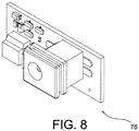
Fig. 8 is an isometric view of a power board in one form. -
Fig. 9 is an isometric view of the power board of one embodiment of the disclosure inverted from the arrangement shown inFig. 8 . -
Fig. 10 is one embodiment of the sensor board, as shown inFig. 5 . -
Fig. 11 is a schematic view of one embodiment of a power supply control circuit. -
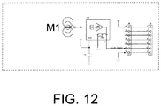
Fig. 12 is a schematic view of one embodiment of a drum sensor circuit. -
Fig. 13 is a schematic view of one embodiment of a sensor control circuit. -
Figure 14 is an isometric view of another embodiment of the disclosure with the parts exploded. -
Fig. 15 is an exploded view of the power board of one embodiment of the disclosure. -
Fig. 16 is one embodiment of the sensor board as shown inFig. 14 . - Before beginning, to aid in understanding, an
axis system 10 is shown inFig. 1 comprising avertical axis 12, atransverse axis 14, and alateral axis 16. These directional terms as used in this description may aid in describing the embodiments of the disclosure and are not to be construed as limiting the embodiments to any particular orientation during operation, or in connection to another apparatus. - According to one embodiment of the disclosure, as shown in
Fig. 1 , a hands-free/manual hybrid dispenser 20 is disclosed comprising afront cover 22 and aback cover 24. Thefront cover 22 in one embodiment is coupled to theback cover 24 at a lower vertical position by way of ahinge 26. In the embodiments shown inFig. 6 and7 , afront cover 28 and a backside 30 are coupled by way of ahinge 32 along one lateral side. Referring back toFig. 1 , the upper vertical portion of thefront cover 22 is secured to theback cover 24 by way of alatch 34. Similarly, the embodiment shown inFig. 7 is coupled by way of a latch 36 on one lateral side. - In one embodiment, to allow visual observation of the condition of the roll of product within the casing, a
view window 38 may be provided in one lateral side. Also, aproduct outlet 40 is shown in the lowermost portion adjacent amanual actuator 42. When one of the dispensing systems disclosed herein is activated, a portion of the sheet product will exit through thisproduct outlet 40 such that a user can grasp it and remove it. - While similar towel dispensers are well known in the art having a front cover, a back cover, and a product outlet, the novel feature of this design is the hybrid actuating mechanism comprising both an automatic dispensing system and a manual dispensing system. The dispenser is configured such that a user reaching toward the
manual actuator 42 will activate anobject sensor 43 having a field ofview 44 projecting through theuser engagement surface 46 of themanual actuator 42. In this way, before the user contacts theuser engagement surface 46, the sensor should detect the proximity of the user and automatically dispense a portion of product, given that the automatic dispensing system is functioning properly. If the automatic dispensing system is not actuating properly, the user will continue to reach toward themanual actuator 42, contacting theuser engagement surface 46 and thus putting pressure upon themanual actuator 40 to manually dispense a portion of product. - In the embodiment shown in
Fig. 2 , themanual actuator 42 comprises acover plate 48 which is attached to theuser engagement surface 46, such that when themanual actuator 42 is engaged and pressed toward theback cover 24, thecover plate 48 repositions to an interior portion of the cabinet. Thecover plate 48 repositions above abottom plate 50 which is rigidly affixed, to or formed as a unitary structure with, theback cover 24. In one embodiment, theobject sensor 43 is disposed transversely behind theuser engagement surface 46 such that the field ofview 44 of theobject sensor 43 projects through theuser engagement surface 46. In one form, an indicator light 134 positioned behind theorifice 52 illuminates when thesensor 43 detects a user. For example, the indicator light may comprise a colored light, for example green, which will blink when a user is detected. The indicator light may be used to indicate other conditions, such as a steady green light when the dispenser is ready to dispense more product or a red light which may blink to indicate a low battery condition. Theobject sensor 43 will tend to reposition relative to the casing along with themanual actuator 42 when themanual actuator 42 is engaged. As thesensor 43 will be in communication with an automatic drive mechanism, a plurality of wires may be disposed vertically above thecover plate 48 within thedispenser 20 to protect them from wear and tear, and also to protect them from a negligent user. - The embodiment shown in
Figs. 1 and2 is also shown inFig. 3 with thefront cover 22 removed to more clearly show the internal workings thereof. Additionally, a sheet product holder, commonly known in the art, will be disposed in theupper portion 54 of theback cover 24. This sheet product holder is not shown to allow an easier understanding of the other workings of this dispenser. In one form, the sheet product holder is coupled via a plurality ofextrusions back cover 24. Also shown is a plurality ofattachment openings 60 provided in thebackside 62 ofback cover 24, such that thetowel dispenser 20 can be attached to a wall, door, or other surface. - Moving now to
Fig. 5 , an exploded view of the integral parts of one embodiment is shown. Beginning with thefront cover 22 and ending with theback cover 24, several of the parts will be explained and discussed. To operate in an automatic dispensing mode, a power supply is utilized to provide power to thesensor 43, themotor 108, and any control or indicator circuitry. Where it is desired that thetowel dispenser 20 be self-contained, abattery tray 64 containing a plurality ofbatteries 66 may be included. To protect thesebatteries 66, abattery tray cover 68 is configured to be positioned adjacent thebatteries 66 to complete the enclosure formed by thebattery tray 64. Thebattery tray 64,batteries 66, andbattery tray cover 68 interoperate as aDC power supply 70. ThisDC power supply 70 in one form is physically coupled to theproduct guide assembly 72. Theproduct guide assembly 72 substantially functions to direct the product from the product roll, past adrive roller 74 and to exit through theproduct outlet 40, where it can be utilized. - The
product guide assembly 72 in one form removably couples to theback cover 24 and also serves as a mounting location for apower board 76. Thispower board 76 is shown in more detail inFig. 9 and will be discussed in more detail herein. On one or both sides of theproduct guide assembly 72 is adrive mechanism 78. Thedrive mechanism 78 substantially comprises a plurality of gears, including adriver gear 80, an idler gear 82, and a drivengear 84. These gears 80, 82 and 84 generally comprise agear assembly 86 which is mounted to adrive mechanism plate 88. In one form, thedriver gear 80 further comprises a one-way bearing, such that manual activation of the dispenser will not harm the motor and associated mechanism and/or automatic activation will not engage the manual assembly. Thedrive mechanism plate 88 couples to theproduct guide assembly 72 and also forms an attachment for aroller assembly 90, including a pinch roller 136. - In one form, the
roller assembly 90 comprises adrive roller 74 having a rightdrive roller cap 92 and a leftdrive roller cap 94 removably affixed to either lateral end of thedrive roller 74. Thedrive roller 74 is coupled to thedrive mechanism 78 through a plurality ofdrive axles axles gear 84 such that when the drivengear 84 rotates, force is translated to thedrive roller 74 which is in frictional engagement with a portion of the sheet product, and as thedrive roller 74 rotates in a given direction, a portion of the sheet product is dispensed through theproduct outlet 40. - In one form, a
sensor plate 100 fits within arecess 102 within a front portion of themanual actuator 42. This sensor plate in 100 comprises thesensor 43 previously discussed. To further protect thesensor board 100, asensor cover 104 is disposed upon theupper surface 106 of themanual actuator 42 encloses therecess 102. While thesensor board 100 may be in communication with thepower board 76 through several different methods, a plurality of wires, which are not shown, will route power to thesensor board 100 and will also function to provide a signal by which themotor 108 is engaged. When themotor 108 is engaged and operational, theshaft 110 drives the drivengear 84 to rotate thegear assembly 86 to rotate thedrive roller 74 and thus dispense a portion of product. In one form, themanual actuator 42 is coupled to aleft side plate 112 and aright side plate 114. Each of these side plates includes apivot 116 configured to interoperate with apivot pin 118 coupled to thedrive mechanism plate 88. Aleft ratchet 120 andright ratchet 122 are also fitted and coupled to theleft side plate 112 andright side plate 114 respectively. These ratchets have a plurality ofteeth 124 which are configured to interoperate with thegear assembly 86 only when themanual actuator 42 is utilized to dispense a portion of product. When themanual actuator 42 is not utilized, a spring or other member will position it and the attachedratchets gear assembly 86. Thus the automatic dispensing assembly will be allowed to function unhindered by the manual advance assembly. When themanual actuator 42 is manually engaged, the ratchet(s) and associated teeth will engage the teeth of thegear assembly 86, manually advancing a portion of product. - One form of the values of the components shown in the embodiment of circuit diagrams of
Figs. 11-13 is listed below. Other embodiments may also be utilized, without departing from the scope of the disclosure. -
- C1 - 0.1 uF
- C2 - 0.1 uF
- C3 - 0.1 uF
- C4 - 1.0
uF 10% - C5 - 0.1 uF
- C6 - 0.01 uF
- C7 - 0.1 uF
- C8 - 2u2F 1206 20% 10V
- C9 - 2u2F 1206 20% 10V
-
- D1 - GSOT15-GS08
- TRANSISTORS
- Q1 - NTR4503N (for reverse battery protection)
- Q2 - NTR4503N
-
- R1 -
- R2 - 10k
- R3-11K31%
- R4 - 10K
- R5 - 10K
- R6-10K1%
- R7 - 100R
- R8 - 100R
- R9 - 10K
- R10 -
- R11 - 10K
-
J1 - CUI POWER JACK PJ 015A (Plugging in the adapter will open connection from negative battery terminal to ground)
J2 - JSTHDR S2B PH SM4 (Battery tray)
J3 - JST HDR S2B PH SM4 (2-wire motor connector)
J4 - SM SIP 7X1.00MM (Board to board cable harness)
J5 - SM SIP 7X1.00MM (Board to board cable harness)
J6 - 5PIN SIP 050MIL Programming & Development Header
J7 - 6PIN SIP 100MIL UART Debug Connector
J8 - SM SIP 7X1.00MM
J9 - SM SIP 7X1.00MM
M1 - Drum Magnet
M2 - Door magnet
TP1 - TP PTH 035MIL (Blade static strap grounding point)
TP5 - TP PTH 030 MIL
S1 - TYCO SP3T STS131PC04 (Paper length selector)Slider (S1) Position Short Sense Long Sense Paper Length 1-2 high low Short 2-3 low low Medium 3-4 low high Long
U1 - SOT-23-5 LP2980IM5-3.3
U3 - ALLEGRO A3211 SOT-23W (Drum Rotation Sensor)
U4 - PIC16F726 SOIC-28, SSOP-28
U5 - ALLEGRO A3211 (Chassis open / paddle activation sensor) -
- 1. All resistors are thick film, 0603, 1/10W, 5% tolerance unless specified.
- 2. All capacitors are X7R, 0603, 50V, 20% tolerance unless specified.
- 3. All test points (TPnn) are 40mil diameter pads (no drill hole) unless otherwise specified.
- 4. D1.2 (NC) is connected to VBAT for ease/convenience of routing VBAT on PCB
- When the
automatic advance assembly 126 is operating, a user will reach toward theuser engagement surface 46 of themanual actuator 42, entering the field ofview 44 of thesensor 43, which thus sends a signal to themotor 108 which will function to automatically dispense a portion of product. When the automatic advance assembly is not operational, such as when no power supply is available, themanual advance assembly 128 will be utilized as previously discussed. Once a portion of product is dispensed, thecutter 138 is utilized to separate the dispensed portion from the remaining portion of product. - While the term "field of view" is used in this description of the embodiments, this should not be understood to be limited to a visual sensor. In one embodiment, the
sensor plate 100 is formed as a capacitive sensor which can detect objects within a limited range. Even though there is no visual aspect to these sensors, the term "field of view" is still often used to determine the area in which an object can be sensed. Such capacitive sensors are a relatively recent innovation, and are often found in personal computer touch pads and portable media players including mobile phones. An article in Electronic Product Design (EPD) Magazine of December 1, 2006 does a relatively good job of explaining the operation of the users. A capacitive sensor in one form is acopper sensor plate 100 connected to acontroller circuit 130 as shown inFig. 13 . Thissensor plate 100 may be formed on the same substrate as thecontroller circuit 130. Thiscontroller circuit 130 detects input as a change in capacitance of thesensor 100. In one form, thecontroller circuit 130 simultaneously may sense an open casing door by way of a sensor sensing the magnetic flux field from a door magnet M2 ofFig. 13 or equivalent sensor. Thecontroller circuit 130 may also include a drum rotation sensor sensing the magnetic flux field from a drum magnet M1. In some experimental dispensers, rotation of thedrive roller 74 was mistaken as a user in proximity to thesensor plate 100. This faulty sensing is a problem in that the apparatus may continue to dispense product continuously. Thus it will be desired to dispense a portion of product and discontinue sensing while themotor 108 and/or driveroller 74 are in operation. Additionally, a maintenance person checking on the status of the volume of product remaining in thedispenser 20 or replacing the same will tend to set off dispensing of the product. This is not desired when the front cover is opened, allowing access to the interior for replacing of the product, the replacing of the batteries, or other actions. Thus, when the door magnet M2 detects that thefront cover 22 is in the open position, thecontroller circuit 130 will not allow dispensing of product. In one form, theindicator light 134 will indicate that the dispenser is not ready to dispense product, such as by a red blinking light - Depending on many factors such as location, common use, clientele, financial concerns etc., it may be desired to control the amount of product dispensed in each cycle. Therefore, a paper
length adjustment switch 132 may be provided as shown inFigs. 9 and11 . One possible placement of the paperlength adjustment switch 132 is upon thepower board 76 as shown inFig. 5 . In one form, the paperlength adjustment switch 132 comprises a single pull triple throw selector switch which will allow for short, medium, or long paper lengths being dispensed during each cycle. Obviously other selector switches could be utilized for a wide range of paper lengths. - In the embodiment shown in
Fig. 14 , the dispensing and cutting apparatus, as disclosed in applicants'U.S. Published Patent Application No. 2007-0079676 A2 , is combined with the sensor device located in the manual actuator shown above. - The connector J2 in one form may be a connection to an external power source or a battery supply. To protect against polarity problems in the event that a battery is placed in backwards, a reverse battery protector Q1 may be provided. A power supply portion S1 in one form provides a select switch which allows a user to select between short, medium and long paper lengths. The switch Q2 provides a switch for the motor to use a very low-cost switch for a hot lead. Connector J6 in one form is a program connector coupled to the microcontroller or main processor U4. This connector J6 is utilized as the product is assembled. There is a small portion of the power supply electrically isolated in one form, so it can be programmed without the product being taken apart. A cable connection may be utilized between J4 and J5 to electronically communicate between the two circuit boards shown in
Fig 15 and 16 . The circuit U4 is a main processor which in one form includes acapacitive flux sensor 100b which is a copper surface forming part of a capacitor. Forming the sensor as a printed circuit in combination with the main processor U4 provides an inexpensive, compact, and convenient sensor/ The entire microcontroller may be disposed within the push bar 42B ofFig. 14 . Thus the microcontroller operates as a capacitor and comprises a large copper surface on the circuit board itself. Edge circuit boards are provided with copper where the construction allows for layers of copper to be placed on the board to create the capacitance pad. - Sensor U5 is a sensor which senses a magnetic flux field from a magnet M2 which in one form is positioned with the casing door 22B. The magnet effectively communicates when the casing door 22B is open and further when the casing door 22B is open, the ability of the dispenser to automatically provide product is disabled. Therefore the magnet switch U5 in one form doubles as a manual advance push bar sensor and a detector of when the chassis is open. When the manual advance push bar 42B is pushed, the automatic advance assembly 126B is disabled from providing product. Therefore, as shown in
Fig. 16 , the sensor U5 has two functions of detecting whether the chassis is open and further detect when the manual advance push bar 42B has been engaged, whereby any sort of activation from the copper pad proximity sensor 100B would be effectively temporarily disabled. - One form of the values of the components shown in the embodiment of circuit diagrams of
Figs. 14-16 is listed below. Other embodiments may also be utilized, without departing from the scope of the disclosure. -
- C1 - 2u2uF
- C2 - 0.1 uF
- C3 - 0.1 uF
- C4 - 1.0uF
- C5 - 0.1uF
- C6 - 0.01 uF
- C7 - 0.1uF
- C8 - 2u2F
- C9 - 2u2F
- D1 - 15MA20CTAT3
-
- Q1 - NTR4503N (for reverse battery protection)
- Q2 - NTR4503N
-
- R1 - 100R
- R2 - 100R
- R3 - 30K1
- R4 - 10K
- R5 - 10K
- R6 - 10K
- R7 - 100R
- R9 - 10K
- R10 - 10K
- R11 - 10K
-
J1 - CUI POWER JACK PJ 015A (Plugging in the adapter will open connection from negative battery terminal to ground)
J2 - S2B PH SM4 (Battery tray)
J3 - JST HDR S2B PH SM4-TB (2-wire motor connector)
J4 - SM SIP 9X1.00MM (Board to board cable harness)
J5 - SM SIP 9X1.00MM (Board to board cable harness)
J6 - 5PIN SIP 050MIL Programming & Development Header
J7 - 6PIN SIP 100MIL UART Debug Connector
M1 - Drum Magnet
M2 - Door magnet
TP1 - TP PTH 035MIL (Blade static strap grounding point)
TP5 - TP PTH 030 MIL
S1 - TYCO SP3T STS131PC04 (Paper length selector)Slider (S1) Position Short Sense Long Sense Paper Length 1-2 high low Short 2-3 low low Medium 3-4 low high Long
U1 - SOT-23-5 LP2980IM5-3.3
U3 - ALLEGRO A322EUA-T (Drum Rotation Sensor)
U4 - PIC16F726 SOIC-28, SSOP-28 -
- 1. All resistors are thick film, 0603, 1/10W, 5% tolerance unless specified.
- 2. All capacitors are X7R, 0603, 50V, 20% tolerance unless specified.
- 3. All test points (TPnn) are 40mil diameter pads (no drill hole) unless otherwise specified.
- 4. D1.2 (NC) is connected to VBAT for ease/convenience of routing VBAT on PCB
- In the embodiment shown in
Fig. 14 , the length of dispensed product is determined by time of operation of the motor. Therefore, the charge of the battery influences the length of the motor operation, and thus the length of the dispensed product. In the version shown inFig. 14 , which relates to a drum cutting embodiment, the rotational sensor U3 ofFig. 12 detects a certain rotation of the drum 74B and the over centered spring takes over, providing rotation thereof for a fixed increment amount of towel length based upon the diameter of the drum 74B. With the version shown inFig. 5 , which in one embodiment is a manual tear system, the circuitry allows for a general reading of the battery power which has an influence upon the velocity of the actuator motor advancing the product the proper distance so as to increment a prescribed amount of product per activation of the sensor. The available energy in a battery is related to its voltage. Therefore, in a battery, the terminal voltage drop is fairly linear over time; they typically have 1.5 volts brand-new and are "dead" when there is .85 volts of differential between the terminals. As the batteries are no longer functional at this point, the external power supply (if operational) or themanual advance assembly 128 can be used to dispense product.
Claims (16)
- A product dispenser (20) configured to dispense sheet product from a roll of sheet product comprising:a. at least one drive roller (74) operatively configured to frictionally engage a portion of the sheet product and expel the portion of sheet product when rotated;b. an automatic advance assembly comprising a motor (108) operatively coupled to the drive roller (74) and operatively configured to rotate the drive roller (74) when the motor (108) is activated;c. an object sensor (43) in contact with the automatic advance assembly, the object sensor (43) being electrically coupled to the motor (108) and operatively configured to detect an object proximate to the object sensor (43), before the object physically contacts the object sensor (43);d. a manual advance assembly (42) coupled to the drive roller (74); the manual advance assembly comprising an engagement surface (46), the manual advance assembly (43) manually operably a user to rotate the drive roller (74);e. a one way coupling (80) operatively configured to engage the motor (108) to the roll of sheet product when the object sensor (43) engages the automatic advance assembly, and disengage the motor (108) from the roll of sheet product when the user pulls on the leading edge of the sheet product or otherwise engages the manual advance assembly (42) such that the portion of the sheet product is dispensed; andf. the product dispenser characterized by the object sensor (43) having a field of view in front of the engagement surface (46) of the manual advance assembly (42) for sensing an object in the field of view, with the object sensor (43) affixed or coupled to the manual advance assembly (42) such that the object sensor (43) moves with the engagement surface (46) of the manual advance assembly (42) when the manual advance assembly (42) is utilized.
- The product dispenser(20) as recited in Claim 1 wherein the object sensor (43) is formed as a portion of a printed circuit board in combination with a microprocessor circuit (U4).
- The product dispenser (20) as recited in Claim 1 wherein the object sensor (43) comprises at least one of a motion sensor, infrared sensor, light sensor, laser sensor, or an acoustic sensor positioned upon the manual advance assembly.
- The product dispenser (20) as recited in Claim 1 wherein the object sensor comprises a plate capacitance proximity sensor (100b) positioned within the manual advance assembly (42).
- The product dispenser (20) as recited in Claim 1 further comprising a one-way coupling operatively configured to couple the motor (103) to the drive roller (74) when rotated in a first direction and decouple the motor (108) from the drive roller (74) when rotated in an opposite second direction, thereby enabling the motor (103) to rotate the drive roller (74) in an automatic dispensing mode and the user to rotate the drive roller (74) in a manual dispensing mode.
- The product dispenser (20) as recited in claim 1 consisting of a single drive roller (74).
- The product dispenser (20) as recited in Claim 1 comprising at least two drive rollers wherein one drive roller (74) is coupled to the automatic advance assembly, and the second drive roller (74B) is coupled to the manual advance assembly.
- The product dispenser (20) as recited in claim 5 wherein the coupling (80) is a one-way bearing.
- The product dispenser (20) as recited in claim 1 further comprising a self-contained power supply (70).
- The product dispenser (20) as recited in Claim 1 further comprising circuitry (U3) to influence the length of sheet product dispensed in an automatic mode based in part on the power remaining in the self-contained power supply (70).
- The product dispenser (20) as recited in Claim 10 further comprising an AC power connection (J2), operatively configured to disconnect the electric connection between the battery tray (64) and the motor (108) and object sensor (43) when the AC power connection (J2) is utilized.
- The product dispenser (20) as recited in Claim 1 wherein the manual advance assembly (42) further comprises a push bar (46) pivotally coupled to the drive roller (74), and the manual advance assembly is operatively configured such that the user exerts force upon the push bar (46) to operate the manual advance assembly (42).
- The product dispenser (20) as recited in Claim 1 further comprising a drive roller sensor and circuitry (130) operatively configured to detect rotation of the drive roller (74) and delay the dispensing of a second portion of product for an interval.
- The product dispenser (20) as recited in Claim 1 further comprising a casing door open sensor (100) operatively configured to detect when the casing door is open and delay the dispensing of a portion of product.
- The product dispenser (20) as recited in Claim 14 further wherein the casing door open sensor (100) is operatively configured to additionally detect when the manual advance assembly is utilized and delay the automatic dispensing of a portion of product.
- The product dispenser (20) as recited in Claim 1 further comprising a paper length adjustment switch (132) operatively configured to allow adjustability of the length of the dispensed portion of sheet product.
Applications Claiming Priority (2)
| Application Number | Priority Date | Filing Date | Title |
|---|---|---|---|
| US14499409P | 2009-01-15 | 2009-01-15 | |
| PCT/US2010/021150 WO2010083380A1 (en) | 2009-01-15 | 2010-01-15 | Paper roll dispenser with sensor attached to manual actuator |
Publications (3)
| Publication Number | Publication Date |
|---|---|
| EP2391487A1 EP2391487A1 (en) | 2011-12-07 |
| EP2391487A4 EP2391487A4 (en) | 2015-04-01 |
| EP2391487B1 true EP2391487B1 (en) | 2017-03-29 |
Family
ID=42340094
Family Applications (1)
| Application Number | Title | Priority Date | Filing Date |
|---|---|---|---|
| EP10732129.1A Not-in-force EP2391487B1 (en) | 2009-01-15 | 2010-01-15 | Paper roll dispenser with sensor attached to manual actuator |
Country Status (4)
| Country | Link |
|---|---|
| US (1) | US8528851B2 (en) |
| EP (1) | EP2391487B1 (en) |
| CA (1) | CA2749834C (en) |
| WO (1) | WO2010083380A1 (en) |
Families Citing this family (31)
| Publication number | Priority date | Publication date | Assignee | Title |
|---|---|---|---|---|
| US7837077B2 (en) * | 2006-03-28 | 2010-11-23 | Sca Tissue North America, Llc | Hands-free powered absorbent sheet dispenser |
| US9345367B2 (en) * | 2009-05-27 | 2016-05-24 | Dispensing Dynamics International | Multi-function paper toweling dispenser |
| WO2012174630A1 (en) * | 2011-06-21 | 2012-12-27 | Dispensing Dynamics International Ltd. | Electronic roll towel dispenser |
| EP2760773A4 (en) | 2011-09-26 | 2015-03-04 | Cascades Canada Ulc | Rolled product dispenser with multiple cutting blades and cutter assembly for a rolled product dispenser |
| US9730559B2 (en) * | 2014-04-10 | 2017-08-15 | Dispensing Dynamics International, Llc | Electro-mechanical paper sheet material dispenser with tail sensor |
| WO2015163802A1 (en) * | 2014-04-25 | 2015-10-29 | Sca Hygiene Products Ab | An interface for an automatic hygienic sheet paper dispenser |
| US9701508B2 (en) | 2015-02-06 | 2017-07-11 | Georgia-Pacific Consumer Products Lp | Hybrid dispenser systems |
| US12029355B2 (en) | 2015-06-04 | 2024-07-09 | Kimberly-Clark Worldwide, Inc. | Dispenser for rolled sheet materials with motorized spindle |
| US11109722B2 (en) | 2015-06-04 | 2021-09-07 | Charles Agnew Osborne, Jr. | Dispenser for rolled sheet materials |
| US12150599B2 (en) | 2015-06-04 | 2024-11-26 | Kimberly-Clark Worldwide, Inc. | Dispenser for rolled sheet materials with motorized spindle |
| US11344165B2 (en) | 2015-06-04 | 2022-05-31 | Kimberly-Clark Worldwide, Inc. | Dispenser for rolled sheet materials with cutting system |
| US11395566B2 (en) | 2016-04-11 | 2022-07-26 | Gpcp Ip Holdings Llc | Sheet product dispenser |
| US11412900B2 (en) | 2016-04-11 | 2022-08-16 | Gpcp Ip Holdings Llc | Sheet product dispenser with motor operation sensing |
| US12358750B2 (en) | 2016-12-20 | 2025-07-15 | Charles Agnew Osborne, Jr. | Cutting system for a dispenser |
| EP3579732B1 (en) | 2017-03-17 | 2025-02-12 | Kimberly-Clark Worldwide, Inc. | Monitoring system for dispenser |
| EP3624658A1 (en) | 2017-05-19 | 2020-03-25 | Bradley Fixtures Corporation | Automatic paper towel dispenser with lidar sensor |
| US10850938B2 (en) | 2017-10-09 | 2020-12-01 | Gpcp Ip Holdings Llc | Mechanical sheet product dispenser |
| USD860674S1 (en) * | 2018-02-06 | 2019-09-24 | San Jamar, Inc. | Towel dispenser |
| USD862109S1 (en) | 2018-05-16 | 2019-10-08 | Bradley Fixtures Corporation | Housing for a roll towel dispenser |
| CA3099743A1 (en) | 2018-05-16 | 2019-11-21 | Bradley Fixtures Corporation | Roll towel dispenser |
| USD854347S1 (en) | 2018-05-16 | 2019-07-23 | Bradley Fixtures Corporation | Roller for a roll towel dispenser |
| US12268341B2 (en) | 2018-05-24 | 2025-04-08 | Charles Agnew Osborne, Jr. | Sheet material dispensing assembly with integrated gear clutch |
| WO2019226668A1 (en) | 2018-05-24 | 2019-11-28 | Osborne Charles Agnew Jr | Dispenser for rolled sheet materials |
| US11154166B2 (en) | 2018-05-24 | 2021-10-26 | Charles Agnew Osborne, Jr. | Dispenser for rolled sheet materials |
| US11771271B1 (en) * | 2018-12-20 | 2023-10-03 | Christopher J. Danis | Dispensing assembly for paper products |
| CA3124098A1 (en) * | 2018-12-31 | 2020-07-09 | Kimberly-Clark Worldwide, Inc. | Dispenser manual feed detection system |
| JP2021048747A (en) * | 2019-09-20 | 2021-03-25 | 日本電産トーソク株式会社 | Circuit board and electric oil pump |
| EP4051069A4 (en) * | 2019-10-31 | 2023-07-12 | Kimberly-Clark Worldwide, Inc. | Electronic towel dispenser with low power mode |
| WO2021236026A1 (en) * | 2020-05-18 | 2021-11-25 | Inceoeren Ali | Automat for disposable and hygienic cover |
| EP4329571A4 (en) * | 2021-04-28 | 2025-01-15 | Kimberly-Clark Worldwide, Inc. | DISTRIBUTOR COMPRISING AN ELECTRONIC CARD IN A FRONT COVER ASSEMBLY |
| US11812897B1 (en) | 2022-02-20 | 2023-11-14 | Christopher J. Danis | Dispensing assembly for paper products |
Family Cites Families (17)
| Publication number | Priority date | Publication date | Assignee | Title |
|---|---|---|---|---|
| US3737087A (en) * | 1972-05-24 | 1973-06-05 | Mirra Cote Co Inc | Dispensing apparatus for rolled materials |
| US4666099A (en) * | 1985-11-15 | 1987-05-19 | Scott Paper Company | Apparatus for dispensing sheet material |
| US6695246B1 (en) | 1996-02-16 | 2004-02-24 | Bay West Paper Corporation | Microprocessor controlled hands-free paper towel dispenser |
| US5772291A (en) | 1996-02-16 | 1998-06-30 | Mosinee Paper Corporation | Hands-free paper towel dispensers |
| US6412679B2 (en) | 1998-05-20 | 2002-07-02 | Georgia-Pacific Corporation | Paper towel dispenser |
| US7044421B1 (en) * | 1999-04-20 | 2006-05-16 | The Colman Group, Inc. | Electronically controlled roll towel dispenser with data communication system |
| US6892620B2 (en) | 2001-12-19 | 2005-05-17 | Kimberly-Clark Worldwide, Inc. | Electro-mechanical roll product dispenser |
| CA2390411A1 (en) | 2002-06-03 | 2003-12-03 | Alwin Manufacturing Company, Incorporated | Automatic dispenser apparatus |
| WO2006072006A2 (en) * | 2004-12-30 | 2006-07-06 | The Colman Group, Inc. | Improved dispenser for sheet material |
| AU2005334401B2 (en) * | 2005-07-13 | 2010-06-17 | Sca Hygiene Products Ab | Automated dispenser |
| US20070079676A1 (en) | 2005-10-07 | 2007-04-12 | Global Plastics | Paper dispenser |
| US8082827B2 (en) * | 2005-10-07 | 2011-12-27 | Dispensing Dynamics International Ltd. | Hybrid towel dispenser |
| US20070176041A1 (en) * | 2005-10-07 | 2007-08-02 | Global Plastics | Automated toilet paper dispenser |
| US20070194166A1 (en) * | 2006-02-18 | 2007-08-23 | Georgia-Pacific Consumer Products Lp | Electronic Dispenser for Dispensing Sheet Products |
| US7523885B2 (en) * | 2006-10-31 | 2009-04-28 | Kimberly-Clark Worldwide, Inc. | Hands-free electronic towel dispenser with power saving feature |
| US20100102101A1 (en) * | 2008-10-28 | 2010-04-29 | Perrin Manufacturing Company | Paper toweling dispenser apparatus |
| US8382026B2 (en) * | 2009-05-27 | 2013-02-26 | Dispensing Dynamics International | Multi-function paper toweling dispenser |
-
2010
- 2010-01-15 EP EP10732129.1A patent/EP2391487B1/en not_active Not-in-force
- 2010-01-15 CA CA2749834A patent/CA2749834C/en active Active
- 2010-01-15 US US12/688,157 patent/US8528851B2/en not_active Expired - Fee Related
- 2010-01-15 WO PCT/US2010/021150 patent/WO2010083380A1/en not_active Ceased
Also Published As
| Publication number | Publication date |
|---|---|
| US8528851B2 (en) | 2013-09-10 |
| US20100176237A1 (en) | 2010-07-15 |
| WO2010083380A8 (en) | 2011-03-03 |
| CA2749834A1 (en) | 2010-07-22 |
| EP2391487A4 (en) | 2015-04-01 |
| CA2749834C (en) | 2016-03-15 |
| EP2391487A1 (en) | 2011-12-07 |
| WO2010083380A1 (en) | 2010-07-22 |
Similar Documents
| Publication | Publication Date | Title |
|---|---|---|
| CA2749834C (en) | Paper roll dispenser with sensor attached to manual actuator | |
| CA2469032C (en) | Electrical roll product dispenser | |
| US7398944B2 (en) | Hands-free electronic towel dispenser | |
| US7624664B2 (en) | Apparatus and methods usable in connection with dispensing flexible sheet material from a roll | |
| CA2906327C (en) | Electronic residential tissue dispenser | |
| CN114630608B (en) | Electronic tissue dispenser with low power mode | |
| CA2477599C (en) | Apparatus and method to dispense flexible material | |
| JP6126333B2 (en) | Roll paper towel dispenser |
Legal Events
| Date | Code | Title | Description |
|---|---|---|---|
| PUAI | Public reference made under article 153(3) epc to a published international application that has entered the european phase |
Free format text: ORIGINAL CODE: 0009012 |
|
| 17P | Request for examination filed |
Effective date: 20110812 |
|
| AK | Designated contracting states |
Kind code of ref document: A1 Designated state(s): AT BE BG CH CY CZ DE DK EE ES FI FR GB GR HR HU IE IS IT LI LT LU LV MC MK MT NL NO PL PT RO SE SI SK SM TR |
|
| DAX | Request for extension of the european patent (deleted) | ||
| RA4 | Supplementary search report drawn up and despatched (corrected) |
Effective date: 20150303 |
|
| RIC1 | Information provided on ipc code assigned before grant |
Ipc: A47K 10/36 20060101ALI20150225BHEP Ipc: B26D 7/00 20060101AFI20150225BHEP |
|
| GRAP | Despatch of communication of intention to grant a patent |
Free format text: ORIGINAL CODE: EPIDOSNIGR1 |
|
| INTG | Intention to grant announced |
Effective date: 20161125 |
|
| GRAS | Grant fee paid |
Free format text: ORIGINAL CODE: EPIDOSNIGR3 |
|
| GRAA | (expected) grant |
Free format text: ORIGINAL CODE: 0009210 |
|
| AK | Designated contracting states |
Kind code of ref document: B1 Designated state(s): AT BE BG CH CY CZ DE DK EE ES FI FR GB GR HR HU IE IS IT LI LT LU LV MC MK MT NL NO PL PT RO SE SI SK SM TR |
|
| REG | Reference to a national code |
Ref country code: GB Ref legal event code: FG4D |
|
| REG | Reference to a national code |
Ref country code: CH Ref legal event code: EP |
|
| REG | Reference to a national code |
Ref country code: AT Ref legal event code: REF Ref document number: 879303 Country of ref document: AT Kind code of ref document: T Effective date: 20170415 |
|
| REG | Reference to a national code |
Ref country code: IE Ref legal event code: FG4D |
|
| REG | Reference to a national code |
Ref country code: DE Ref legal event code: R096 Ref document number: 602010041112 Country of ref document: DE |
|
| REG | Reference to a national code |
Ref country code: DE Ref legal event code: R082 Ref document number: 602010041112 Country of ref document: DE Representative=s name: ARNOLD & SIEDSMA, DE Ref country code: DE Ref legal event code: R081 Ref document number: 602010041112 Country of ref document: DE Owner name: DISPENSING DYNAMICS INTERNATIONAL, LLC, CITY O, US Free format text: FORMER OWNER: DISPENSING DYNAMICS INTERNATIONAL, CITY OF INDUSTRY, CALIF., US |
|
| PG25 | Lapsed in a contracting state [announced via postgrant information from national office to epo] |
Ref country code: FI Free format text: LAPSE BECAUSE OF FAILURE TO SUBMIT A TRANSLATION OF THE DESCRIPTION OR TO PAY THE FEE WITHIN THE PRESCRIBED TIME-LIMIT Effective date: 20170329 Ref country code: HR Free format text: LAPSE BECAUSE OF FAILURE TO SUBMIT A TRANSLATION OF THE DESCRIPTION OR TO PAY THE FEE WITHIN THE PRESCRIBED TIME-LIMIT Effective date: 20170329 Ref country code: GR Free format text: LAPSE BECAUSE OF FAILURE TO SUBMIT A TRANSLATION OF THE DESCRIPTION OR TO PAY THE FEE WITHIN THE PRESCRIBED TIME-LIMIT Effective date: 20170630 Ref country code: NO Free format text: LAPSE BECAUSE OF FAILURE TO SUBMIT A TRANSLATION OF THE DESCRIPTION OR TO PAY THE FEE WITHIN THE PRESCRIBED TIME-LIMIT Effective date: 20170629 Ref country code: LT Free format text: LAPSE BECAUSE OF FAILURE TO SUBMIT A TRANSLATION OF THE DESCRIPTION OR TO PAY THE FEE WITHIN THE PRESCRIBED TIME-LIMIT Effective date: 20170329 |
|
| REG | Reference to a national code |
Ref country code: NL Ref legal event code: MP Effective date: 20170329 |
|
| REG | Reference to a national code |
Ref country code: AT Ref legal event code: MK05 Ref document number: 879303 Country of ref document: AT Kind code of ref document: T Effective date: 20170329 |
|
| PG25 | Lapsed in a contracting state [announced via postgrant information from national office to epo] |
Ref country code: BG Free format text: LAPSE BECAUSE OF FAILURE TO SUBMIT A TRANSLATION OF THE DESCRIPTION OR TO PAY THE FEE WITHIN THE PRESCRIBED TIME-LIMIT Effective date: 20170629 Ref country code: LV Free format text: LAPSE BECAUSE OF FAILURE TO SUBMIT A TRANSLATION OF THE DESCRIPTION OR TO PAY THE FEE WITHIN THE PRESCRIBED TIME-LIMIT Effective date: 20170329 Ref country code: SE Free format text: LAPSE BECAUSE OF FAILURE TO SUBMIT A TRANSLATION OF THE DESCRIPTION OR TO PAY THE FEE WITHIN THE PRESCRIBED TIME-LIMIT Effective date: 20170329 |
|
| PG25 | Lapsed in a contracting state [announced via postgrant information from national office to epo] |
Ref country code: NL Free format text: LAPSE BECAUSE OF FAILURE TO SUBMIT A TRANSLATION OF THE DESCRIPTION OR TO PAY THE FEE WITHIN THE PRESCRIBED TIME-LIMIT Effective date: 20170329 |
|
| PG25 | Lapsed in a contracting state [announced via postgrant information from national office to epo] |
Ref country code: EE Free format text: LAPSE BECAUSE OF FAILURE TO SUBMIT A TRANSLATION OF THE DESCRIPTION OR TO PAY THE FEE WITHIN THE PRESCRIBED TIME-LIMIT Effective date: 20170329 Ref country code: AT Free format text: LAPSE BECAUSE OF FAILURE TO SUBMIT A TRANSLATION OF THE DESCRIPTION OR TO PAY THE FEE WITHIN THE PRESCRIBED TIME-LIMIT Effective date: 20170329 Ref country code: ES Free format text: LAPSE BECAUSE OF FAILURE TO SUBMIT A TRANSLATION OF THE DESCRIPTION OR TO PAY THE FEE WITHIN THE PRESCRIBED TIME-LIMIT Effective date: 20170329 Ref country code: SK Free format text: LAPSE BECAUSE OF FAILURE TO SUBMIT A TRANSLATION OF THE DESCRIPTION OR TO PAY THE FEE WITHIN THE PRESCRIBED TIME-LIMIT Effective date: 20170329 Ref country code: RO Free format text: LAPSE BECAUSE OF FAILURE TO SUBMIT A TRANSLATION OF THE DESCRIPTION OR TO PAY THE FEE WITHIN THE PRESCRIBED TIME-LIMIT Effective date: 20170329 Ref country code: CZ Free format text: LAPSE BECAUSE OF FAILURE TO SUBMIT A TRANSLATION OF THE DESCRIPTION OR TO PAY THE FEE WITHIN THE PRESCRIBED TIME-LIMIT Effective date: 20170329 |
|
| PG25 | Lapsed in a contracting state [announced via postgrant information from national office to epo] |
Ref country code: PT Free format text: LAPSE BECAUSE OF FAILURE TO SUBMIT A TRANSLATION OF THE DESCRIPTION OR TO PAY THE FEE WITHIN THE PRESCRIBED TIME-LIMIT Effective date: 20170731 Ref country code: SM Free format text: LAPSE BECAUSE OF FAILURE TO SUBMIT A TRANSLATION OF THE DESCRIPTION OR TO PAY THE FEE WITHIN THE PRESCRIBED TIME-LIMIT Effective date: 20170329 Ref country code: PL Free format text: LAPSE BECAUSE OF FAILURE TO SUBMIT A TRANSLATION OF THE DESCRIPTION OR TO PAY THE FEE WITHIN THE PRESCRIBED TIME-LIMIT Effective date: 20170329 Ref country code: IS Free format text: LAPSE BECAUSE OF FAILURE TO SUBMIT A TRANSLATION OF THE DESCRIPTION OR TO PAY THE FEE WITHIN THE PRESCRIBED TIME-LIMIT Effective date: 20170729 |
|
| REG | Reference to a national code |
Ref country code: DE Ref legal event code: R097 Ref document number: 602010041112 Country of ref document: DE |
|
| PG25 | Lapsed in a contracting state [announced via postgrant information from national office to epo] |
Ref country code: DK Free format text: LAPSE BECAUSE OF FAILURE TO SUBMIT A TRANSLATION OF THE DESCRIPTION OR TO PAY THE FEE WITHIN THE PRESCRIBED TIME-LIMIT Effective date: 20170329 |
|
| PLBE | No opposition filed within time limit |
Free format text: ORIGINAL CODE: 0009261 |
|
| STAA | Information on the status of an ep patent application or granted ep patent |
Free format text: STATUS: NO OPPOSITION FILED WITHIN TIME LIMIT |
|
| 26N | No opposition filed |
Effective date: 20180103 |
|
| PG25 | Lapsed in a contracting state [announced via postgrant information from national office to epo] |
Ref country code: SI Free format text: LAPSE BECAUSE OF FAILURE TO SUBMIT A TRANSLATION OF THE DESCRIPTION OR TO PAY THE FEE WITHIN THE PRESCRIBED TIME-LIMIT Effective date: 20170329 |
|
| REG | Reference to a national code |
Ref country code: CH Ref legal event code: PL |
|
| PG25 | Lapsed in a contracting state [announced via postgrant information from national office to epo] |
Ref country code: LU Free format text: LAPSE BECAUSE OF NON-PAYMENT OF DUE FEES Effective date: 20180115 Ref country code: FR Free format text: LAPSE BECAUSE OF NON-PAYMENT OF DUE FEES Effective date: 20180131 |
|
| REG | Reference to a national code |
Ref country code: IE Ref legal event code: MM4A |
|
| REG | Reference to a national code |
Ref country code: FR Ref legal event code: ST Effective date: 20180928 |
|
| REG | Reference to a national code |
Ref country code: BE Ref legal event code: MM Effective date: 20180131 |
|
| PG25 | Lapsed in a contracting state [announced via postgrant information from national office to epo] |
Ref country code: BE Free format text: LAPSE BECAUSE OF NON-PAYMENT OF DUE FEES Effective date: 20180131 Ref country code: LI Free format text: LAPSE BECAUSE OF NON-PAYMENT OF DUE FEES Effective date: 20180131 Ref country code: CH Free format text: LAPSE BECAUSE OF NON-PAYMENT OF DUE FEES Effective date: 20180131 |
|
| PG25 | Lapsed in a contracting state [announced via postgrant information from national office to epo] |
Ref country code: IE Free format text: LAPSE BECAUSE OF NON-PAYMENT OF DUE FEES Effective date: 20180115 |
|
| PG25 | Lapsed in a contracting state [announced via postgrant information from national office to epo] |
Ref country code: MC Free format text: LAPSE BECAUSE OF FAILURE TO SUBMIT A TRANSLATION OF THE DESCRIPTION OR TO PAY THE FEE WITHIN THE PRESCRIBED TIME-LIMIT Effective date: 20170329 |
|
| PG25 | Lapsed in a contracting state [announced via postgrant information from national office to epo] |
Ref country code: MT Free format text: LAPSE BECAUSE OF NON-PAYMENT OF DUE FEES Effective date: 20180115 |
|
| PG25 | Lapsed in a contracting state [announced via postgrant information from national office to epo] |
Ref country code: TR Free format text: LAPSE BECAUSE OF FAILURE TO SUBMIT A TRANSLATION OF THE DESCRIPTION OR TO PAY THE FEE WITHIN THE PRESCRIBED TIME-LIMIT Effective date: 20170329 |
|
| PG25 | Lapsed in a contracting state [announced via postgrant information from national office to epo] |
Ref country code: HU Free format text: LAPSE BECAUSE OF FAILURE TO SUBMIT A TRANSLATION OF THE DESCRIPTION OR TO PAY THE FEE WITHIN THE PRESCRIBED TIME-LIMIT; INVALID AB INITIO Effective date: 20100115 |
|
| PG25 | Lapsed in a contracting state [announced via postgrant information from national office to epo] |
Ref country code: MK Free format text: LAPSE BECAUSE OF NON-PAYMENT OF DUE FEES Effective date: 20170329 Ref country code: CY Free format text: LAPSE BECAUSE OF FAILURE TO SUBMIT A TRANSLATION OF THE DESCRIPTION OR TO PAY THE FEE WITHIN THE PRESCRIBED TIME-LIMIT Effective date: 20170329 |
|
| PGFP | Annual fee paid to national office [announced via postgrant information from national office to epo] |
Ref country code: GB Payment date: 20221201 Year of fee payment: 14 |
|
| PGFP | Annual fee paid to national office [announced via postgrant information from national office to epo] |
Ref country code: IT Payment date: 20221213 Year of fee payment: 14 Ref country code: DE Payment date: 20221130 Year of fee payment: 14 |
|
| REG | Reference to a national code |
Ref country code: DE Ref legal event code: R119 Ref document number: 602010041112 Country of ref document: DE |
|
| GBPC | Gb: european patent ceased through non-payment of renewal fee |
Effective date: 20240115 |
|
| PG25 | Lapsed in a contracting state [announced via postgrant information from national office to epo] |
Ref country code: DE Free format text: LAPSE BECAUSE OF NON-PAYMENT OF DUE FEES Effective date: 20240801 |
|
| PG25 | Lapsed in a contracting state [announced via postgrant information from national office to epo] |
Ref country code: GB Free format text: LAPSE BECAUSE OF NON-PAYMENT OF DUE FEES Effective date: 20240115 |
|
| PG25 | Lapsed in a contracting state [announced via postgrant information from national office to epo] |
Ref country code: GB Free format text: LAPSE BECAUSE OF NON-PAYMENT OF DUE FEES Effective date: 20240115 Ref country code: DE Free format text: LAPSE BECAUSE OF NON-PAYMENT OF DUE FEES Effective date: 20240801 |
|
| PG25 | Lapsed in a contracting state [announced via postgrant information from national office to epo] |
Ref country code: IT Free format text: LAPSE BECAUSE OF NON-PAYMENT OF DUE FEES Effective date: 20240115 |