EP2391082A2 - Radio communication base station device and radio communication method - Google Patents
Radio communication base station device and radio communication method Download PDFInfo
- Publication number
- EP2391082A2 EP2391082A2 EP11167327A EP11167327A EP2391082A2 EP 2391082 A2 EP2391082 A2 EP 2391082A2 EP 11167327 A EP11167327 A EP 11167327A EP 11167327 A EP11167327 A EP 11167327A EP 2391082 A2 EP2391082 A2 EP 2391082A2
- Authority
- EP
- European Patent Office
- Prior art keywords
- subcarrier
- interval
- cell search
- frequency
- sch
- Prior art date
- Legal status (The legal status is an assumption and is not a legal conclusion. Google has not performed a legal analysis and makes no representation as to the accuracy of the status listed.)
- Granted
Links
Images


Classifications
-
- H—ELECTRICITY
- H04—ELECTRIC COMMUNICATION TECHNIQUE
- H04J—MULTIPLEX COMMUNICATION
- H04J11/00—Orthogonal multiplex systems, e.g. using WALSH codes
- H04J11/0069—Cell search, i.e. determining cell identity [cell-ID]
-
- H—ELECTRICITY
- H04—ELECTRIC COMMUNICATION TECHNIQUE
- H04L—TRANSMISSION OF DIGITAL INFORMATION, e.g. TELEGRAPHIC COMMUNICATION
- H04L27/00—Modulated-carrier systems
- H04L27/26—Systems using multi-frequency codes
- H04L27/2601—Multicarrier modulation systems
- H04L27/2602—Signal structure
- H04L27/26025—Numerology, i.e. varying one or more of symbol duration, subcarrier spacing, Fourier transform size, sampling rate or down-clocking
-
- H—ELECTRICITY
- H04—ELECTRIC COMMUNICATION TECHNIQUE
- H04L—TRANSMISSION OF DIGITAL INFORMATION, e.g. TELEGRAPHIC COMMUNICATION
- H04L27/00—Modulated-carrier systems
- H04L27/26—Systems using multi-frequency codes
- H04L27/2601—Multicarrier modulation systems
- H04L27/2626—Arrangements specific to the transmitter only
-
- H—ELECTRICITY
- H04—ELECTRIC COMMUNICATION TECHNIQUE
- H04L—TRANSMISSION OF DIGITAL INFORMATION, e.g. TELEGRAPHIC COMMUNICATION
- H04L27/00—Modulated-carrier systems
- H04L27/26—Systems using multi-frequency codes
- H04L27/2601—Multicarrier modulation systems
- H04L27/2647—Arrangements specific to the receiver only
- H04L27/2655—Synchronisation arrangements
- H04L27/2657—Carrier synchronisation
-
- H—ELECTRICITY
- H04—ELECTRIC COMMUNICATION TECHNIQUE
- H04L—TRANSMISSION OF DIGITAL INFORMATION, e.g. TELEGRAPHIC COMMUNICATION
- H04L5/00—Arrangements affording multiple use of the transmission path
- H04L5/0001—Arrangements for dividing the transmission path
- H04L5/0003—Two-dimensional division
- H04L5/0005—Time-frequency
- H04L5/0007—Time-frequency the frequencies being orthogonal, e.g. OFDM(A) or DMT
-
- H—ELECTRICITY
- H04—ELECTRIC COMMUNICATION TECHNIQUE
- H04L—TRANSMISSION OF DIGITAL INFORMATION, e.g. TELEGRAPHIC COMMUNICATION
- H04L5/00—Arrangements affording multiple use of the transmission path
- H04L5/003—Arrangements for allocating sub-channels of the transmission path
- H04L5/0053—Allocation of signalling, i.e. of overhead other than pilot signals
-
- H—ELECTRICITY
- H04—ELECTRIC COMMUNICATION TECHNIQUE
- H04W—WIRELESS COMMUNICATION NETWORKS
- H04W48/00—Access restriction; Network selection; Access point selection
- H04W48/08—Access restriction or access information delivery, e.g. discovery data delivery
-
- H—ELECTRICITY
- H04—ELECTRIC COMMUNICATION TECHNIQUE
- H04W—WIRELESS COMMUNICATION NETWORKS
- H04W48/00—Access restriction; Network selection; Access point selection
- H04W48/16—Discovering, processing access restriction or access information
-
- H—ELECTRICITY
- H04—ELECTRIC COMMUNICATION TECHNIQUE
- H04W—WIRELESS COMMUNICATION NETWORKS
- H04W56/00—Synchronisation arrangements
- H04W56/001—Synchronization between nodes
- H04W56/0015—Synchronization between nodes one node acting as a reference for the others
-
- H—ELECTRICITY
- H04—ELECTRIC COMMUNICATION TECHNIQUE
- H04W—WIRELESS COMMUNICATION NETWORKS
- H04W72/00—Local resource management
-
- H—ELECTRICITY
- H04—ELECTRIC COMMUNICATION TECHNIQUE
- H04W—WIRELESS COMMUNICATION NETWORKS
- H04W72/00—Local resource management
- H04W72/04—Wireless resource allocation
- H04W72/044—Wireless resource allocation based on the type of the allocated resource
- H04W72/0453—Resources in frequency domain, e.g. a carrier in FDMA
-
- H—ELECTRICITY
- H04—ELECTRIC COMMUNICATION TECHNIQUE
- H04W—WIRELESS COMMUNICATION NETWORKS
- H04W8/00—Network data management
- H04W8/005—Discovery of network devices, e.g. terminals
-
- H—ELECTRICITY
- H04—ELECTRIC COMMUNICATION TECHNIQUE
- H04W—WIRELESS COMMUNICATION NETWORKS
- H04W88/00—Devices specially adapted for wireless communication networks, e.g. terminals, base stations or access point devices
- H04W88/08—Access point devices
Definitions
- the present invention relates to a radio communication base station apparatus and a radio communication method.
- a radio communication mobile station apparatus performs a cell search upon power activation or upon handover.
- This cell search is performed using an SCH (synchronization channel).
- the SCH is a shared channel in the downlink direction and is comprised of a P-SCH (primary synchronization channel) and an S-SCH (secondary synchronization channel).
- P-SCH data contains a sequence which is common in all cells and which is used for the timing synchronization upon the cell search.
- S-SCH data contains cell-specific transmission parameters such as scrambling code information.
- each mobile station finds the timing synchronization by receiving P-SCH data and acquires transmission parameters that differ between cells by receiving S-SCH data.
- each mobile station can start communicating with radio communication base station apparatuses (hereinafter “base stations”). Therefore, each mobile station needs to detect SCH data upon power activation or upon handover.
- base stations radio communication base station apparatuses
- frequencies for setting carriers are arranged at 200 kHz intervals in a 60 MHz frequency bandwidth (see Patent Document 1). Therefore, according to this standard, the frequency interval the mobile station performs a cell search is 200 kHz. That is, the mobile station performs a cell search every 200 kHz.
- the SCH is generally set in the center frequency of the frequency bandwidth in which a mobile station can perform communication.
- Multicarrier communication such as OFDM (Orthogonal Frequency Division Multiplexing) has attracted attention as one of counter techniques for frequency selective fading.
- Multicarrier communication refers to a technique of performing high speed transmission by transmitting data using a plurality of subcarriers of transmission rates suppressed to such an extent that frequency selective fading does not occur.
- frequencies of a plurality of subcarriers where data is arranged are orthogonal to each other, thereby enabling the maximum frequency efficiency in multicarrier communication and implementation with relatively simple hardware configuration.
- the OFDM scheme has attracted attention as a communication method applied to cellular scheme mobile communication and is variously studied.
- the interval between adjacent subcarriers (subcarrier intervals) in a plurality of subcarriers is set according to the coherence bandwidth (the frequency bandwidth in which channel fluctuation is the same) of this communication system.
- This mobile communication system can be referred to as a "scalable bandwidth communication system.”
- the scalable bandwidth communication system having a 20 MHz operating frequency bandwidth
- the 20 MHz operating frequency bandwidth is equally divided per 5 MHz frequency bandwidth into four frequency bands FB1 FB2, FB3 and FB4
- the mobile station having the minimum communication capacity is referred to as the "minimum capacity mobile station”
- the mobile station having the maximum communication capacity is referred to as the "maximum capacity mobile station.” Therefore, in this case, the mobile station having the 5 MHz communication capacity is the minimum capacity mobile station and the mobile station having the 20 MHz communication capacity is the maximum capacity mobile station.
- the mobile station having a 2.1 MHz communication capacity is the minimum capacity mobile station and the mobile station having a 4.2 MHz communication capacity is the maximum capacity mobile station.
- a mobile station having a 2.1 MHz communication capacity is referred to as a "2.1 MHz mobile station,” and a mobile station having a 4.2 MHz communication capacity is referred to as a "4.2 MHz mobile station.”
- the 2.1 MHz mobile station is assigned a 2.1 MHz frequency bandwidth out of the 4.2 MHz frequency bandwidth and performs communication. That is, the 2.1 MHz mobile station is assigned one of FB1 and FB2 and performs communication.
- the 4.2 MHz mobile station can perform high speed communication using the entire 4.2 MHz operating frequency bandwidth.
- the frequency bandwidth, in which the maximum capacity mobile station can perform communication generally matches the frequency bandwidth where a scalable bandwidth communication system is operated (in this case, 4.2 MHz).
- the SCH is set in the center frequency of the frequency bandwidth in which a mobile station can perform communication
- the mobile station that performs a cell search at predetermined cell search intervals as above may not be able to perform a cell search.
- the SCH for the 4.2 MHz mobile station is set in the center frequency f cl of a 4.2 MHz frequency bandwidth
- the SCH for the 2.1 MHz mobile station is set in the center frequency f c2 of a 2.1 MHz frequency bandwidth.
- the subcarrier interval is set 150 kHz according to the coherence bandwidth in the communication system.
- the cell search interval is 200 kHz as above.
- the center frequency f cl is set a frequency that is an integral multiple of the 200 kHz cell search interval, although the 4.2 MHz mobile station can detect the SCH, the 150 kHz subcarrier interval makes the 2.1 MHz mobile station unable to detect the SCH and perform a cell search.
- the center frequency f c2 is set the frequency that is an integral multiple of the 200 kHz cell search interval, although the 2.1 MHz mobile station can detect the SCH, the 150 kHz subcarrier interval makes the 4.2 MHz mobile station unable to detect the SCH and perform a cell search.
- the OFDM scheme is applied to a scalable bandwidth communication system where there are a plurality of mobile stations communicating in respective bandwidths, there are mobile stations that cannot perform a cell search depending on the relationship between the subcarrier interval and the cell search interval.
- One possible solution to this problem is to decide the subcarrier interval according to the cell search interval. To be more specific, making the cell subcarrier a divisor of the search interval interval, is possible. However, with this solution, it is not always possible to set an optimal subcarrier interval according to the coherence bandwidth, and, consequently, throughput degradation and error rate performance degradation may be caused.
- the radio communication base station of the present invention that transmits a multicarrier signal comprised of a plurality of subcarriers, employs a configuration having: a setting section that sets one of the plurality of subcarriers as a first subcarrier for transmitting a synchronization channel signal; a generating section that generates the multicarrier signal by mapping the synchronization channel signal on the first subcarrier; and a transmitting section that transmits the multicarrier signal, and the configuration in which, among the plurality of subcarriers, the setting section sets, as the first subcarrier, one of subcarriers having frequencies of common multiples of the subcarrier interval between the plurality of subcarriers and a frequency interval in which a radio communication mobile station performs a cell search.
- all of a plurality of mobile stations communicating in respective frequency bandwidths can perform a cell search in the scalable bandwidth communication system adopting, for example, the OFDM scheme.
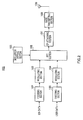
- FIG.2 illustrates the configuration of base station 100.
- Encoding section 101 encodes SCH data.
- Modulating section 102 modulates the encoded SCH data.
- Encoding section 103 encodes user data.
- Modulating section 104 modulates the encoded user data.
- Subcarrier setting section 105 sets one of a plurality of subcarriers forming an OFDM symbol, which is a multicarrier signal, as the subcarrier for transmitting SCH data (SCH subcarrier). This subcarrier setting will be described later in detail.
- IFFT section 106 maps SCH data and user data on the multiple subcarriers above and performs an IFFT (Inverse Fast Fourier Transform), thereby generating an OFDM symbol.
- IFFT section 106 maps SCH data on the subcarrier set in subcarrier setting section 105.
- the OFDM symbol generated as above is attached a cyclic prefix (CP) in CP attaching section 107, subjected to predetermined radio processing such as up-conversion in radio transmitting section 108, and transmitted by radio from antenna 109 to mobile stations.
- CP cyclic prefix
- the tail end of each ODFM symbol is attached to the head of that OFDM symbol as a CP.
- a mobile station which is the receiving side can prevent ISI as long as the delay time of delay weaves stays within the range of the CP time period.
- subcarrier setting in subcarrier setting section 105 will be explained in detail.
- Setting examples 1 to 3 (FIG's.3 to 5) will be explained below.
- the scalable bandwidth communication system is assumed where the operating frequency bandwidth is 4.2 MHz and there are a 2.1 MHz mobile station and a 4.2 MHz mobile station. Further, assume that the subcarrier interval is set 150 kHz as above. Further, assume that the cell search interval is set 200 kHz as above.
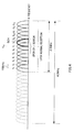
- Subcarrier setting section 105 sets, as the SCH subcarrier, one of subcarriers having frequencies of common multiples of the subcarrier interval and the cell search interval, among the above multiple subcarriers. That is, subcarrier setting section 105 sets, as the SCH subcarrier, one of subcarriers having frequencies of common multiples of the 150 kHz subcarrier interval and the 200 kHz cell search interval (600 kHz x n, where n is a natural number). To be more specific, for example, as shown in FIG.3 , subcarrier setting section 105 sets, as the SCH subcarrier, subcarrier f 12 having a frequency 1.8 MHz greater than the center frequency f cl of 4.2 MHz. Therefore, for example, if the center frequency f cl is set 2GHz, the frequency of subcarrier f 12 is 2001.8 MHz, which is an integral multiple of the 200 kHz cell search interval.
- the SCH can be set in a subcarrier having an integral multiple frequency of the cell search interval among a plurality of subcarriers having predetermined subcarrier intervals, so that both the 2.1 MHz mobile station and the 4.2 MHz mobile station having the same cell search interval can detect the SCH and perform a cell search.
- the 2.1 MHz mobile station needs not change the communication frequency band between the time during cell search and other times such as during normal reception, and, consequently, is able to receive all user data that can be received during normal reception during cell search, so that it is possible to prevent throughput degradation according to the change of the communication frequency band. Further, the 2.1 MHz mobile station needs not change the communication frequency band between the time during cell search and the time during normal reception, that is, the 2.1 MHz mobile station needs not switch the center frequency in radio reception between the time during cell search and the time during normal reception, so that it is possible to ease control upon a cell search and reduce power consumption of mobile stations.
- subcarrier setting section 105 sets, as the SCH subcarrier, the subcarrier that is closest to the center frequency of the frequency bandwidth in which a mobile station can perform communication, out of subcarriers having frequencies of common multiples of the subcarrier interval and the cell search interval.
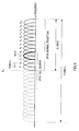
- subcarrier setting section 105 sets, as the SCH subcarrier, subcarrier f 8 that is closest to the center frequency f c2 of 2.1 MHz, out of subcarriers having 600 x n frequencies (n is a natural number). That is, with the present setting example, among the subcarriers having 600 kHz x n frequencies (n is a natural number), the SCH subcarrier is set in the subcarrier that is closest to the center frequency of a frequency bandwidth which is narrower than the operating frequency bandwidth of the scalable bandwidth communication system and in which mobile stations other than the maximum capacity mobile stations can perform communication.
- all of a plurality of mobile stations communicating in respective frequency bandwidths need not switch the center frequency in radio communication between the time during cell search and the time during normal reception, so that it is desirable to set, as the SCH subcarrier, the subcarrier that is closest to the center frequency of the frequency bandwidth in which the maximum capacity mobile station can perform communication.
- the SCH can be set in a subcarrier having an integral multiple frequency of the cell search interval among a plurality of subcarriers having predetermined subcarrier intervals, so that the 2.1 MHz mobile station and the 4.2 MHz mobile station having the same cell search interval can detect the SCH and perform a cell search.
- the 2.1 MHz mobile station needs not change the communication frequency band between the time during cell search and the other times such as during normal reception, and, consequently, is able to receive all user data that can be received during normal reception during cell search, so that it is possible to prevent throughput degradation according to the change of the communication frequency band.
- the 2.1 MHz mobile station needs not change the communication frequency band between the time during cell search and the time during normal reception, that is, the 2.1 MHz mobile station needs not switch the center frequency in radio reception between the time during cell search and the time during normal reception, so that it is possible to ease control during cell search and reduce power consumption of mobile stations.
- the communication frequency bandwidth during cell search can be set narrower than the communication frequency bandwidth during normal reception, so that it is possible to make the sampling rate for A/D conversion during cell search smaller than the sampling rate for A/D conversion during normal reception, and, as a result, further reduce power consumption of mobile stations.
- subcarrier setting section 105 sets, as the SCH subcarrier, the subcarrier that is closest to the center frequency of the operating frequency bandwidth of the communication system, among the subcarriers having frequencies of common multiples of the subcarrier interval and the cell search interval.
- subcarrier setting section 105 sets, as the SCH subcarrier, subcarrier f 4 that is closest to the center frequency f cl of 4.2 MHz, among the subcarriers having 600 kHz x n frequencies (n is a natural number). That is, with the present setting example, the SCH subcarrier is set the subcarrier that is closest to the center frequency of the operating frequency bandwidth of the scalable bandwidth communication system, among the subcarriers having 600 kHz x n frequencies (n is a natural number).
- the SCH subcarrier is set the subcarrier that is closest to the center frequency of the frequency bandwidth in which the maximum capacity mobile station can perform communication, among the subcarriers having 600 kHz X n frequencies (n is a natural number).
- the SCH can be set in a subcarrier having an integral multiple frequency of the cell search interval among a plurality of subcarriers having predetermined subcarrier intervals, so that both the 2.1 MHz mobile station and the 4.2 MHz mobile station having the same the cell search interval can detect the SCH and perform a cell search.
- the communication frequency bandwidth during cell search can be set narrower than the communication frequency bandwidth during normal reception, so that it is possible to make the sampling rate for A/D conversion during cell search smaller than the sampling rate for A/D conversion during normal reception, and, as a result, further reduce power consumption of mobile stations.
- the present setting example is particularly useful when there are more maximum capacity mobile stations than the other mobile stations, and setting example 2 is useful in the opposite case.
- the scalable bandwidth communication system adopting a multicarrier communication scheme such as the OFDM scheme, all of a plurality of mobile stations communicating in respective frequency bandwidths are able to perform a cell search.
- the present invention is applicable to other shared channels than the SCH channel.
- a shared channel other than the SCH for example, there are BCH (broadcast channel) and SCCH (shared control channel).
- a base station may be referred to as "Node B,” a mobile station as “UE,” a subcarrier as a “tone,” a cyclic prefix as a “guard interval.”
- each function block employed in the description of each of the aforementioned embodiments may typically be implemented as an LSI constituted by an integrated circuit. These may be individual chips or partially or totally contained on a single chip.
- LSI is adopted here but this may also be referred to as “IC,” “system LSI,” “super LSI,” or “ultra LSI” depending on differing extents of integration.
- circuit integration is not limited to LSI's, and implementation using dedicated circuitry or general purpose processors is also possible.
- FPGA Field Programmable Gate Array
- reconfigurable processor where connections and settings of circuit cells in an LSI can be reconfigured is also possible.
- the radio communication base station apparatus transmitting a multicarrier signal comprised of a plurality of subcarriers
- the radio communication base station apparatus comprises: a setting section that sets one of the plurality of subcarriers as a first subcarrier for transmitting a synchronization channel signal; a generating section that generates the multicarrier signal by mapping the synchronization channel signal on the first subcarrier; and a transmitting section that transmits the multicarrier signal, wherein, among the plurality of subcarriers, the setting section sets, as the first subcarrier, one of subcarriers having frequencies of common multiples of the subcarrier interval between the plurality of subcarriers and a frequency interval in which a radio communication mobile station performs a cell search.
- the setting section sets, as the first subcarrier, a subcarrier that is closest to a center frequency of a frequency bandwidth in which the radio communication mobile station can perform communication, out of the subcarriers having frequencies of common multiples.
- the setting section sets, as the first subcarrier, a subcarrier that is closest to a center subcarrier of an operating frequency bandwidth of a communication system, out of subcarriers having frequencies of common multiples.
- the radio communication method comprises setting, as the first subcarrier, one of subcarriers having frequencies of common multiples of the subcarrier interval of the plurality of subcarriers and a frequency interval in which a radio communication mobile station performs a cell search.
Landscapes
- Engineering & Computer Science (AREA)
- Signal Processing (AREA)
- Computer Networks & Wireless Communication (AREA)
- Databases & Information Systems (AREA)
- Computer Security & Cryptography (AREA)
- Physics & Mathematics (AREA)
- Mathematical Physics (AREA)
- Mobile Radio Communication Systems (AREA)
Abstract
Description
- The present invention relates to a radio communication base station apparatus and a radio communication method.
- In the mobile communication system, a radio communication mobile station apparatus (hereinafter "mobile station") performs a cell search upon power activation or upon handover. This cell search is performed using an SCH (synchronization channel). The SCH is a shared channel in the downlink direction and is comprised of a P-SCH (primary synchronization channel) and an S-SCH (secondary synchronization channel). P-SCH data contains a sequence which is common in all cells and which is used for the timing synchronization upon the cell search. Further, S-SCH data contains cell-specific transmission parameters such as scrambling code information. In a cell search upon power activation or upon handover, each mobile station finds the timing synchronization by receiving P-SCH data and acquires transmission parameters that differ between cells by receiving S-SCH data. By this means, each mobile station can start communicating with radio communication base station apparatuses (hereinafter "base stations"). Therefore, each mobile station needs to detect SCH data upon power activation or upon handover.
- Further, according to the FFD scheme standard proposed by 3GPP, frequencies for setting carriers are arranged at 200 kHz intervals in a 60 MHz frequency bandwidth (see Patent Document 1). Therefore, according to this standard, the frequency interval the mobile station performs a cell search is 200 kHz. That is, the mobile station performs a cell search every 200 kHz.
- Further, to simplify the design of the communication system, the SCH is generally set in the center frequency of the frequency bandwidth in which a mobile station can perform communication.
- By the way, in recent years, in mobile communication, various kinds of information such as images and data as well as speech are subjected to transmission. With this trend, it is expected that demands further increase for high reliability and high speed transmission. However, when high speed transmission is performed in mobile communication, the influence of delayed waves by multipath is not negligible, and transmission performance degrades due to frequency selective fading.
- Multicarrier communication such as OFDM (Orthogonal Frequency Division Multiplexing) has attracted attention as one of counter techniques for frequency selective fading. Multicarrier communication refers to a technique of performing high speed transmission by transmitting data using a plurality of subcarriers of transmission rates suppressed to such an extent that frequency selective fading does not occur. Particularly, with the OFDM scheme, frequencies of a plurality of subcarriers where data is arranged are orthogonal to each other, thereby enabling the maximum frequency efficiency in multicarrier communication and implementation with relatively simple hardware configuration. By this means, the OFDM scheme has attracted attention as a communication method applied to cellular scheme mobile communication and is variously studied. In the communication system employing the OFDM scheme, the interval between adjacent subcarriers (subcarrier intervals) in a plurality of subcarriers, is set according to the coherence bandwidth (the frequency bandwidth in which channel fluctuation is the same) of this communication system.
- Further, at present, according to the LTE standardization of 3GPP, in the mobile communication system with the OFDM scheme, allowing a plurality of mobile stations communicating in respective bandwidths, to perform communication in the system, is studied. This mobile communication system can be referred to as a "scalable bandwidth communication system."
- For example, assuming the scalable bandwidth communication system having a 20 MHz operating frequency bandwidth, if the 20 MHz operating frequency bandwidth is equally divided per 5 MHz frequency bandwidth into four frequency bands FB1 FB2, FB3 and FB4, it is possible to use mobile stations having 5 MHz, 10 MHz or 20 MHz communication capacities at the same time. In the following explanation, out of a plurality of mobile stations that are available, the mobile station having the minimum communication capacity is referred to as the "minimum capacity mobile station," and the mobile station having the maximum communication capacity is referred to as the "maximum capacity mobile station." Therefore, in this case, the mobile station having the 5 MHz communication capacity is the minimum capacity mobile station and the mobile station having the 20 MHz communication capacity is the maximum capacity mobile station.
- Further, for example, assuming the scalable bandwidth communication system with a 4.2 MHz operating frequency bandwidth, if the 4.2 MHz operating bandwidth is divided per 2.1 MHz frequency bandwidth into two bandwidths FB1 and FB2, it is possible to use a mobile station having a 2.1 MHz communication capacity and a mobile station having a 4.2 MHz communication capacity at the same time. Therefore, in the above, the mobile station having a 2.1 MHz communication capacity is the minimum capacity mobile station and the mobile station having a 4.2 MHz communication capacity is the maximum capacity mobile station. A mobile station having a 2.1 MHz communication capacity is referred to as a "2.1 MHz mobile station," and a mobile station having a 4.2 MHz communication capacity is referred to as a "4.2 MHz mobile station." In this scalable bandwidth communication system, the 2.1 MHz mobile station is assigned a 2.1 MHz frequency bandwidth out of the 4.2 MHz frequency bandwidth and performs communication. That is, the 2.1 MHz mobile station is assigned one of FB1 and FB2 and performs communication. Further, the 4.2 MHz mobile station can perform high speed communication using the entire 4.2 MHz operating frequency bandwidth. Here, as described above, the frequency bandwidth, in which the maximum capacity mobile station can perform communication, generally matches the frequency bandwidth where a scalable bandwidth communication system is operated (in this case, 4.2 MHz).
- Patent Document 1: Japanese Patent Application Laid-Open No.
2003-60551 - Problems to be Solved by the Invention
- Here, assuming that the OFDM scheme is applied to a scalable bandwidth communication system as shown in
FIG.1 , if the SCH is set in the center frequency of the frequency bandwidth in which a mobile station can perform communication, the mobile station that performs a cell search at predetermined cell search intervals as above may not be able to perform a cell search. For example, assume that the SCH for the 4.2 MHz mobile station is set in the center frequency fcl of a 4.2 MHz frequency bandwidth, and the SCH for the 2.1 MHz mobile station is set in the center frequency fc2 of a 2.1 MHz frequency bandwidth. Further, assume that the subcarrier interval is set 150 kHz according to the coherence bandwidth in the communication system. Further, assume that the cell search interval is 200 kHz as above. Here, if the center frequency fcl is set a frequency that is an integral multiple of the 200 kHz cell search interval, although the 4.2 MHz mobile station can detect the SCH, the 150 kHz subcarrier interval makes the 2.1 MHz mobile station unable to detect the SCH and perform a cell search. By contrast, if the center frequency fc2 is set the frequency that is an integral multiple of the 200 kHz cell search interval, although the 2.1 MHz mobile station can detect the SCH, the 150 kHz subcarrier interval makes the 4.2 MHz mobile station unable to detect the SCH and perform a cell search. Thus, if the OFDM scheme is applied to a scalable bandwidth communication system where there are a plurality of mobile stations communicating in respective bandwidths, there are mobile stations that cannot perform a cell search depending on the relationship between the subcarrier interval and the cell search interval. - One possible solution to this problem is to decide the subcarrier interval according to the cell search interval. To be more specific, making the cell subcarrier a divisor of the search interval interval, is possible. However, with this solution, it is not always possible to set an optimal subcarrier interval according to the coherence bandwidth, and, consequently, throughput degradation and error rate performance degradation may be caused.
- It is therefore an object of the present invention to provide, in the scalable bandwidth communication system adopting the OFDM scheme, a base station and radio communication scheme for enabling all of a plurality of mobile stations communicating in respective frequency bandwidths, to perform a cell search.
- The radio communication base station of the present invention that transmits a multicarrier signal comprised of a plurality of subcarriers, employs a configuration having: a setting section that sets one of the plurality of subcarriers as a first subcarrier for transmitting a synchronization channel signal; a generating section that generates the multicarrier signal by mapping the synchronization channel signal on the first subcarrier; and a transmitting section that transmits the multicarrier signal, and the configuration in which, among the plurality of subcarriers, the setting section sets, as the first subcarrier, one of subcarriers having frequencies of common multiples of the subcarrier interval between the plurality of subcarriers and a frequency interval in which a radio communication mobile station performs a cell search.
- According to the present invention, all of a plurality of mobile stations communicating in respective frequency bandwidths can perform a cell search in the scalable bandwidth communication system adopting, for example, the OFDM scheme.
-
-
FIG.1 illustrates a scalable bandwidth communication system adopting an OFDM scheme; -
FIG.2 is a block diagram showing a configuration of a base station according to an embodiment of the present invention; -
FIG.3 illustrates an SCH setting example according to an embodiment of the present invention (setting example 1); -
FIG.4 illustrates an SCH setting example according to an embodiment of the present invention (setting example 2); and -
FIG.5 illustrates an SCH setting example according to an embodiment of the present invention (setting example 3). - An embodiment of the present invention will be explained below in detail with reference to the accompanying drawings. Here, in the following explanation, although the OFDM scheme is explained as an example of a multicarrier communication scheme, the present invention is not limited to the OFDM scheme.
-
FIG.2 illustrates the configuration ofbase station 100. -
Encoding section 101 encodes SCH data. - Modulating
section 102 modulates the encoded SCH data. -
Encoding section 103 encodes user data. -
Modulating section 104 modulates the encoded user data. -
Subcarrier setting section 105 sets one of a plurality of subcarriers forming an OFDM symbol, which is a multicarrier signal, as the subcarrier for transmitting SCH data (SCH subcarrier). This subcarrier setting will be described later in detail. - According to the setting in
subcarrier setting section 105,IFFT section 106 maps SCH data and user data on the multiple subcarriers above and performs an IFFT (Inverse Fast Fourier Transform), thereby generating an OFDM symbol. In this case, out of the multiple subcarriers above,IFFT section 106 maps SCH data on the subcarrier set insubcarrier setting section 105. - The OFDM symbol generated as above is attached a cyclic prefix (CP) in
CP attaching section 107, subjected to predetermined radio processing such as up-conversion inradio transmitting section 108, and transmitted by radio fromantenna 109 to mobile stations. - Here, in the OFDM scheme, to prevent intersymbol interference ("ISI"), the tail end of each ODFM symbol is attached to the head of that OFDM symbol as a CP. By this means, a mobile station which is the receiving side can prevent ISI as long as the delay time of delay weaves stays within the range of the CP time period.
- Next, subcarrier setting in
subcarrier setting section 105 will be explained in detail. Setting examples 1 to 3 (FIG's.3 to 5) will be explained below. Here, as above, the scalable bandwidth communication system is assumed where the operating frequency bandwidth is 4.2 MHz and there are a 2.1 MHz mobile station and a 4.2 MHz mobile station. Further, assume that the subcarrier interval is set 150 kHz as above. Further, assume that the cell search interval is set 200 kHz as above. -
Subcarrier setting section 105 sets, as the SCH subcarrier, one of subcarriers having frequencies of common multiples of the subcarrier interval and the cell search interval, among the above multiple subcarriers. That is,subcarrier setting section 105 sets, as the SCH subcarrier, one of subcarriers having frequencies of common multiples of the 150 kHz subcarrier interval and the 200 kHz cell search interval (600 kHz x n, where n is a natural number). To be more specific, for example, as shown inFIG.3 ,subcarrier setting section 105 sets, as the SCH subcarrier, subcarrier f12 having a frequency 1.8 MHz greater than the center frequency fcl of 4.2 MHz. Therefore, for example, if the center frequency fcl is set 2GHz, the frequency of subcarrier f12 is 2001.8 MHz, which is an integral multiple of the 200 kHz cell search interval. - Thus, according to the present setting example, the SCH can be set in a subcarrier having an integral multiple frequency of the cell search interval among a plurality of subcarriers having predetermined subcarrier intervals, so that both the 2.1 MHz mobile station and the 4.2 MHz mobile station having the same cell search interval can detect the SCH and perform a cell search.
- As shown in
FIG.3 , the 2.1 MHz mobile station needs not change the communication frequency band between the time during cell search and other times such as during normal reception, and, consequently, is able to receive all user data that can be received during normal reception during cell search, so that it is possible to prevent throughput degradation according to the change of the communication frequency band. Further, the 2.1 MHz mobile station needs not change the communication frequency band between the time during cell search and the time during normal reception, that is, the 2.1 MHz mobile station needs not switch the center frequency in radio reception between the time during cell search and the time during normal reception, so that it is possible to ease control upon a cell search and reduce power consumption of mobile stations. - In the above multiple subcarriers,
subcarrier setting section 105 sets, as the SCH subcarrier, the subcarrier that is closest to the center frequency of the frequency bandwidth in which a mobile station can perform communication, out of subcarriers having frequencies of common multiples of the subcarrier interval and the cell search interval. - To be more specific, for example, as shown in
FIG.4 ,subcarrier setting section 105 sets, as the SCH subcarrier, subcarrier f8 that is closest to the center frequency fc2 of 2.1 MHz, out of subcarriers having 600 x n frequencies (n is a natural number). That is, with the present setting example, among the subcarriers having 600 kHz x n frequencies (n is a natural number), the SCH subcarrier is set in the subcarrier that is closest to the center frequency of a frequency bandwidth which is narrower than the operating frequency bandwidth of the scalable bandwidth communication system and in which mobile stations other than the maximum capacity mobile stations can perform communication. Specifically, with the present setting example, all of a plurality of mobile stations communicating in respective frequency bandwidths need not switch the center frequency in radio communication between the time during cell search and the time during normal reception, so that it is desirable to set, as the SCH subcarrier, the subcarrier that is closest to the center frequency of the frequency bandwidth in which the maximum capacity mobile station can perform communication. - Therefore, according to the present setting example, as in setting example 1, the SCH can be set in a subcarrier having an integral multiple frequency of the cell search interval among a plurality of subcarriers having predetermined subcarrier intervals, so that the 2.1 MHz mobile station and the 4.2 MHz mobile station having the same cell search interval can detect the SCH and perform a cell search.
- Further, according to the present setting example, as in setting example 1, the 2.1 MHz mobile station needs not change the communication frequency band between the time during cell search and the other times such as during normal reception, and, consequently, is able to receive all user data that can be received during normal reception during cell search, so that it is possible to prevent throughput degradation according to the change of the communication frequency band. Further, the 2.1 MHz mobile station needs not change the communication frequency band between the time during cell search and the time during normal reception, that is, the 2.1 MHz mobile station needs not switch the center frequency in radio reception between the time during cell search and the time during normal reception, so that it is possible to ease control during cell search and reduce power consumption of mobile stations.
- Further, according to the present setting example, as shown in
FIG.4 , the communication frequency bandwidth during cell search can be set narrower than the communication frequency bandwidth during normal reception, so that it is possible to make the sampling rate for A/D conversion during cell search smaller than the sampling rate for A/D conversion during normal reception, and, as a result, further reduce power consumption of mobile stations. - In the above multiple subcarriers,
subcarrier setting section 105 sets, as the SCH subcarrier, the subcarrier that is closest to the center frequency of the operating frequency bandwidth of the communication system, among the subcarriers having frequencies of common multiples of the subcarrier interval and the cell search interval. - To be more specific, for example, as shown in
FIG.5 ,subcarrier setting section 105 sets, as the SCH subcarrier, subcarrier f4 that is closest to the center frequency fcl of 4.2 MHz, among the subcarriers having 600 kHz x n frequencies (n is a natural number). That is, with the present setting example, the SCH subcarrier is set the subcarrier that is closest to the center frequency of the operating frequency bandwidth of the scalable bandwidth communication system, among the subcarriers having 600 kHz x n frequencies (n is a natural number). In other words, with the present setting example, the SCH subcarrier is set the subcarrier that is closest to the center frequency of the frequency bandwidth in which the maximum capacity mobile station can perform communication, among the subcarriers having 600 kHz X n frequencies (n is a natural number). - Therefore, according to the present setting example, as in setting example 1, the SCH can be set in a subcarrier having an integral multiple frequency of the cell search interval among a plurality of subcarriers having predetermined subcarrier intervals, so that both the 2.1 MHz mobile station and the 4.2 MHz mobile station having the same the cell search interval can detect the SCH and perform a cell search.
- Further, according to the present setting example, as shown in
FIG.5 , the communication frequency bandwidth during cell search can be set narrower than the communication frequency bandwidth during normal reception, so that it is possible to make the sampling rate for A/D conversion during cell search smaller than the sampling rate for A/D conversion during normal reception, and, as a result, further reduce power consumption of mobile stations. - Here, compared to the present setting example to setting example 2, while the SCH subcarrier is set the subcarrier having the frequency that is closest to the center frequency fc2 in setting example 2, the SCH subcarrier is set the subcarrier having the frequency that is closest to the center frequency fcl in the present setting example. By this means, the present setting example is particularly useful when there are more maximum capacity mobile stations than the other mobile stations, and setting example 2 is useful in the opposite case.
- Thus, according to the present embodiment, in the scalable bandwidth communication system adopting a multicarrier communication scheme such as the OFDM scheme, all of a plurality of mobile stations communicating in respective frequency bandwidths are able to perform a cell search.
- One embodiment of the present invention has been described above.
- Here, the present invention is applicable to other shared channels than the SCH channel. As a shared channel other than the SCH, for example, there are BCH (broadcast channel) and SCCH (shared control channel).
- Further, a base station may be referred to as "Node B," a mobile station as "UE," a subcarrier as a "tone," a cyclic prefix as a "guard interval."
- Although a case has been described with the above embodiments as an example where the present invention is implemented with hardware, the present invention can be implemented with software.
- Furthermore, each function block employed in the description of each of the aforementioned embodiments may typically be implemented as an LSI constituted by an integrated circuit. These may be individual chips or partially or totally contained on a single chip.
- "LSI" is adopted here but this may also be referred to as "IC," "system LSI," "super LSI," or "ultra LSI" depending on differing extents of integration.
- Further, the method of circuit integration is not limited to LSI's, and implementation using dedicated circuitry or general purpose processors is also possible. After LSI manufacture, utilization of an FPGA (Field Programmable Gate Array) or a reconfigurable processor where connections and settings of circuit cells in an LSI can be reconfigured is also possible.
- Further, if integrated circuit technology comes out to replace LSI's as a result of the advancement of semiconductor technology or a derivative other technology, it is naturally also possible to carry out function block integration using this technology. Application of biotechnology is also possible.
- The disclosure of Japanese Patent Application No.
2006-012436, filed on January 20, 2006 - The present invention is suitable to, for example, OFDM mobile communication systems.
According to an illustrative embodiment of a radio communication base station apparatus transmitting a multicarrier signal comprised of a plurality of subcarriers, the radio communication base station apparatus comprises: a setting section that sets one of the plurality of subcarriers as a first subcarrier for transmitting a synchronization channel signal; a generating section that generates the multicarrier signal by mapping the synchronization channel signal on the first subcarrier; and a transmitting section that transmits the multicarrier signal, wherein, among the plurality of subcarriers, the setting section sets, as the first subcarrier, one of subcarriers having frequencies of common multiples of the subcarrier interval between the plurality of subcarriers and a frequency interval in which a radio communication mobile station performs a cell search.
According to the further embodiment of the radio communication base station apparatus, the setting section sets, as the first subcarrier, a subcarrier that is closest to a center frequency of a frequency bandwidth in which the radio communication mobile station can perform communication, out of the subcarriers having frequencies of common multiples.
According to the further embodiment of the radio communication base station apparatus, the setting section sets, as the first subcarrier, a subcarrier that is closest to a center subcarrier of an operating frequency bandwidth of a communication system, out of subcarriers having frequencies of common multiples.
According to an illustrative embodiment of a radio communication method that sets one of a plurality of subcarriers forming a multicarrier signal, as a first subcarrier for transmitting a synchronization channel signal, the radio communication method comprises setting, as the first subcarrier, one of subcarriers having frequencies of common multiples of the subcarrier interval of the plurality of subcarriers and a frequency interval in which a radio communication mobile station performs a cell search.
Claims (6)
- A base station apparatus comprising:a generating section that generates a synchronization signal mapped on a subcarrier; anda transmission section that transmits the generated synchronization signal,wherein the subcarrier on which the synchronization signal is mapped is included in one of a plurality of frequency resource candidates and an interval between the plurality of frequency resource candidates is common multiples of a subcarrier interval between contiguous subcarriers and a frequency interval for performing a cell search.
- The base station apparatus according to the claim 1, wherein the subcarrier is around a center frequency in said one of the plurality of frequency resource candidates.
- A mobile station apparatus comprising:a detection section that detects a synchronization signal mapped on a subcarrier; anda cell search section that perform a cell search using the detected synchronization signal,wherein the subcarrier on which the synchronization signal is mapped is included in one of a plurality of frequency resource candidates and an interval between the plurality of frequency resource candidates is common multiples of a subcarrier interval between contiguous subcarriers and a frequency interval for performing the cell search.
- The mobile station apparatus according to the claim 3, wherein the subcarrier is around a center frequency in said one of the plurality of frequency resource candidates.
- A transmission method comprising:generating a synchronization signal mapped on a subcarrier; andtransmitting the generated synchronization signal,wherein the subcarrier on which the synchronization signal is mapped is included in one of a plurality of frequency resource candidates and an interval between the plurality of frequency resource candidates is common multiples of a subcarrier interval between contiguous subcarriers and a frequency interval for performing a cell search.
- A reception method comprising:detecting a synchronization signal mapped on a subcarrier; andperforming a cell search using the detected synchronization signal,wherein the subcarrier on which the synchronization signal is mapped is included in one of a plurality of frequency resource candidates and an interval between the plurality of frequency resource candidates is common multiples of a subcarrier interval between contiguous subcarriers and a frequency interval for performing the cell search.
Applications Claiming Priority (3)
| Application Number | Priority Date | Filing Date | Title |
|---|---|---|---|
| JP2006012436 | 2006-01-20 | ||
| PCT/JP2007/050830 WO2007083762A1 (en) | 2006-01-20 | 2007-01-19 | Radio communication base station device and radio communication method |
| EP07707118.1A EP1976169B1 (en) | 2006-01-20 | 2007-01-19 | Radio communication base station device and radio communication method |
Related Parent Applications (3)
| Application Number | Title | Priority Date | Filing Date |
|---|---|---|---|
| EP07707118.1 Division | 2007-01-19 | ||
| EP07707118.1A Division EP1976169B1 (en) | 2006-01-20 | 2007-01-19 | Radio communication base station device and radio communication method |
| EP07707118.1A Division-Into EP1976169B1 (en) | 2006-01-20 | 2007-01-19 | Radio communication base station device and radio communication method |
Publications (3)
| Publication Number | Publication Date |
|---|---|
| EP2391082A2 true EP2391082A2 (en) | 2011-11-30 |
| EP2391082A3 EP2391082A3 (en) | 2017-11-01 |
| EP2391082B1 EP2391082B1 (en) | 2019-09-18 |
Family
ID=38287713
Family Applications (2)
| Application Number | Title | Priority Date | Filing Date |
|---|---|---|---|
| EP11167327.3A Active EP2391082B1 (en) | 2006-01-20 | 2007-01-19 | Radio communication base station device and radio communication method |
| EP07707118.1A Active EP1976169B1 (en) | 2006-01-20 | 2007-01-19 | Radio communication base station device and radio communication method |
Family Applications After (1)
| Application Number | Title | Priority Date | Filing Date |
|---|---|---|---|
| EP07707118.1A Active EP1976169B1 (en) | 2006-01-20 | 2007-01-19 | Radio communication base station device and radio communication method |
Country Status (9)
| Country | Link |
|---|---|
| US (4) | US8130796B2 (en) |
| EP (2) | EP2391082B1 (en) |
| JP (2) | JP5132322B2 (en) |
| KR (3) | KR101246492B1 (en) |
| CN (4) | CN101371478B (en) |
| BR (2) | BRPI0707878B1 (en) |
| IN (1) | IN2014MN01624A (en) |
| RU (2) | RU2421914C2 (en) |
| WO (1) | WO2007083762A1 (en) |
Families Citing this family (26)
| Publication number | Priority date | Publication date | Assignee | Title |
|---|---|---|---|---|
| JP4732967B2 (en) * | 2006-06-19 | 2011-07-27 | 株式会社エヌ・ティ・ティ・ドコモ | Base station equipment |
| JP4992593B2 (en) * | 2007-07-26 | 2012-08-08 | 富士通モバイルコミュニケーションズ株式会社 | Mobile radio terminal device |
| US8594133B2 (en) | 2007-10-22 | 2013-11-26 | Corning Mobileaccess Ltd. | Communication system using low bandwidth wires |
| CN101465830B (en) * | 2007-12-19 | 2012-10-17 | 华为技术有限公司 | Method, system and device for sending and receiving synchronous information |
| CN101262462B (en) * | 2008-02-29 | 2014-07-16 | 中兴通讯股份有限公司 | Transmission method and device for downlink control information |
| KR101642513B1 (en) * | 2008-09-05 | 2016-08-01 | 엘지전자 주식회사 | Method and apparatus for communication using multiple carrier |
| US20110294493A1 (en) * | 2009-11-25 | 2011-12-01 | Qualcomm Incorporated | Modulating cell information on a physical channel |
| WO2013142662A2 (en) | 2012-03-23 | 2013-09-26 | Corning Mobile Access Ltd. | Radio-frequency integrated circuit (rfic) chip(s) for providing distributed antenna system functionalities, and related components, systems, and methods |
| KR101697601B1 (en) * | 2012-11-04 | 2017-01-18 | 엘지전자 주식회사 | Synchronizing signal receiving method and user equipment, and synchronizing signal transmitting method and base station |
| US20140293894A1 (en) * | 2013-03-28 | 2014-10-02 | Coming Optical Communications Wireless, Ltd. | Distributing dynamically frequency-shifted intermediate frequency (if) radio frequency (rf) communications signals in distributed antenna systems (dass), and related components, systems, and methods |
| US9031142B2 (en) * | 2013-09-29 | 2015-05-12 | Harmonic, Inc. | Digital up converter |
| US9112761B1 (en) | 2014-02-13 | 2015-08-18 | Harmonic, Inc. | System and method for routing and up-converting narrowband channels |
| US10103927B2 (en) | 2014-11-06 | 2018-10-16 | Harmonic, Inc. | System and method for distribution of broadcast channels |
| KR102677807B1 (en) | 2016-05-09 | 2024-06-25 | 삼성전자주식회사 | Method and apparatus for transmitting synchronization signal in wirelss cellular communication system |
| WO2017196042A1 (en) * | 2016-05-09 | 2017-11-16 | 삼성전자 주식회사 | Method and device for transmitting/receiving synchronization signal in wireless cellular communication system |
| US10880146B2 (en) | 2016-05-09 | 2020-12-29 | Samsung Electronics Co., Ltd. | Method and device for transmitting/receiving synchronization signal in wireless cellular communication system |
| WO2018012878A1 (en) * | 2016-07-15 | 2018-01-18 | 주식회사 케이티 | Method and device for transmitting/receiving synchronization signal and system information for terminal in new wireless access network |
| EP3493621B1 (en) * | 2016-07-29 | 2021-07-07 | Sharp Kabushiki Kaisha | Terminal device, communication method and integrated circuit |
| US10992510B2 (en) * | 2016-09-30 | 2021-04-27 | Motorola Mobility Llc | Method and apparatus for synchronization signals and random access for flexible radio communication |
| CN110460418B (en) * | 2016-10-10 | 2020-08-07 | 华为技术有限公司 | Synchronization signal transmission method, reception method and device |
| CN112332966A (en) * | 2016-11-27 | 2021-02-05 | 上海朗帛通信技术有限公司 | Method and device in wireless communication |
| CN108540418B (en) * | 2017-03-06 | 2022-05-03 | 中兴通讯股份有限公司 | Data modulation method and device for edge sub-band |
| WO2018174606A1 (en) * | 2017-03-22 | 2018-09-27 | 삼성전자 주식회사 | Method and apparatus for transmitting uplink control channel in wireless cellular communication system |
| KR20180107686A (en) | 2017-03-22 | 2018-10-02 | 삼성전자주식회사 | Method and apparatus for transmitting of uplink control channel in mobile communication system |
| CN110495131B (en) * | 2018-02-21 | 2022-07-08 | 联发科技股份有限公司 | Synchronization signal block grid shifting method and device in mobile communication |
| WO2024063365A1 (en) * | 2022-09-19 | 2024-03-28 | 삼성전자 주식회사 | Electronic device for searching for frequency band, and operating method therefor |
Citations (2)
| Publication number | Priority date | Publication date | Assignee | Title |
|---|---|---|---|---|
| JP2003060551A (en) | 2001-08-09 | 2003-02-28 | Ntt Docomo Inc | Mobile station device, mobile communication system and carrier detection method |
| JP2006012436A (en) | 2004-06-22 | 2006-01-12 | Toray Ind Inc | Display member and display using the same |
Family Cites Families (11)
| Publication number | Priority date | Publication date | Assignee | Title |
|---|---|---|---|---|
| JP3239084B2 (en) * | 1997-05-30 | 2001-12-17 | 株式会社次世代デジタルテレビジョン放送システム研究所 | Multicarrier transmission interleaving apparatus and method |
| RU2154923C1 (en) * | 1997-06-16 | 2000-08-20 | Мицубиси Денки Кабусики Кайся | Mobile communication network |
| JP2000049744A (en) | 1998-05-26 | 2000-02-18 | Victor Co Of Japan Ltd | Transmission band division modulation/demodulation device and its method |
| US6925067B2 (en) | 1999-04-23 | 2005-08-02 | Qualcomm, Incorporated | Configuration of overhead channels in a mixed bandwidth system |
| JP2001175540A (en) * | 1999-12-22 | 2001-06-29 | Nec Corp | Access right management system, portable terminal, gateway and contents server |
| KR100349648B1 (en) * | 1999-12-27 | 2002-08-22 | 주식회사 큐리텔 | Apparatus for calculating decision parameter in wireless telecommunication system |
| JP4204168B2 (en) * | 2000-03-24 | 2009-01-07 | 三洋電機株式会社 | Band pass filter and receiving apparatus using the same |
| JP4523708B2 (en) | 2000-09-05 | 2010-08-11 | 株式会社日立国際電気 | CDMA base station apparatus |
| US7304939B2 (en) * | 2001-12-03 | 2007-12-04 | Nortel Networks Limited | Communication using simultaneous orthogonal signals |
| US20070021130A1 (en) * | 2003-01-29 | 2007-01-25 | Akinori Taira | Multi-carrier radio communication system, transmission device, and reception device |
| JP4583054B2 (en) * | 2004-03-05 | 2010-11-17 | 株式会社エヌ・ティ・ティ・ドコモ | Mobile station and base station |
-
2007
- 2007-01-19 KR KR1020117008981A patent/KR101246492B1/en active Active
- 2007-01-19 EP EP11167327.3A patent/EP2391082B1/en active Active
- 2007-01-19 RU RU2008129720/09A patent/RU2421914C2/en active
- 2007-01-19 WO PCT/JP2007/050830 patent/WO2007083762A1/en not_active Ceased
- 2007-01-19 CN CN2007800027680A patent/CN101371478B/en active Active
- 2007-01-19 CN CN201110389653.XA patent/CN102438227B/en active Active
- 2007-01-19 KR KR1020117030269A patent/KR101246489B1/en active Active
- 2007-01-19 US US12/160,483 patent/US8130796B2/en active Active
- 2007-01-19 KR KR1020087017670A patent/KR101297041B1/en active Active
- 2007-01-19 CN CN2011103910838A patent/CN102497344A/en active Pending
- 2007-01-19 CN CN201110152024.5A patent/CN102209060B/en active Active
- 2007-01-19 JP JP2007554986A patent/JP5132322B2/en active Active
- 2007-01-19 BR BRPI0707878A patent/BRPI0707878B1/en active IP Right Grant
- 2007-01-19 BR BRPI0722415-0A patent/BRPI0722415B1/en active IP Right Grant
- 2007-01-19 EP EP07707118.1A patent/EP1976169B1/en active Active
- 2007-01-19 IN IN1624MUN2014 patent/IN2014MN01624A/en unknown
-
2011
- 2011-03-10 RU RU2011109040/07A patent/RU2550158C2/en active
- 2011-04-13 JP JP2011088795A patent/JP5383738B2/en active Active
- 2011-05-24 US US13/114,696 patent/US8134998B2/en active Active
-
2012
- 2012-01-27 US US13/360,472 patent/US8750283B2/en active Active
-
2014
- 2014-03-03 US US14/195,693 patent/US8897288B2/en active Active
Patent Citations (2)
| Publication number | Priority date | Publication date | Assignee | Title |
|---|---|---|---|---|
| JP2003060551A (en) | 2001-08-09 | 2003-02-28 | Ntt Docomo Inc | Mobile station device, mobile communication system and carrier detection method |
| JP2006012436A (en) | 2004-06-22 | 2006-01-12 | Toray Ind Inc | Display member and display using the same |
Also Published As
Similar Documents
| Publication | Publication Date | Title |
|---|---|---|
| US8134998B2 (en) | Radio communication base station apparatus and radio communication method | |
| US20240292427A1 (en) | Communication apparatus and communication method | |
| EP1971064A2 (en) | Initial access channel for scalable wireless mobile communication networks | |
| US20090046701A1 (en) | Radio communication base station apparatus and synchronization channel signal transmission method | |
| MX2008009043A (en) | Radio communication base station device and radio communication method |
Legal Events
| Date | Code | Title | Description |
|---|---|---|---|
| AC | Divisional application: reference to earlier application |
Ref document number: 1976169 Country of ref document: EP Kind code of ref document: P |
|
| AK | Designated contracting states |
Kind code of ref document: A2 Designated state(s): AT BE BG CH CY CZ DE DK EE ES FI FR GB GR HU IE IS IT LI LT LU LV MC NL PL PT RO SE SI SK TR |
|
| AX | Request for extension of the european patent |
Extension state: AL BA HR MK RS |
|
| PUAI | Public reference made under article 153(3) epc to a published international application that has entered the european phase |
Free format text: ORIGINAL CODE: 0009012 |
|
| RAP1 | Party data changed (applicant data changed or rights of an application transferred) |
Owner name: PANASONIC INTELLECTUAL PROPERTY CORPORATION OF AME |
|
| RAP1 | Party data changed (applicant data changed or rights of an application transferred) |
Owner name: SUN PATENT TRUST |
|
| REG | Reference to a national code |
Ref country code: DE Ref legal event code: R079 Ref document number: 602007059242 Country of ref document: DE Free format text: PREVIOUS MAIN CLASS: H04L0027260000 Ipc: H04J0011000000 |
|
| PUAL | Search report despatched |
Free format text: ORIGINAL CODE: 0009013 |
|
| AK | Designated contracting states |
Kind code of ref document: A3 Designated state(s): AT BE BG CH CY CZ DE DK EE ES FI FR GB GR HU IE IS IT LI LT LU LV MC NL PL PT RO SE SI SK TR |
|
| AX | Request for extension of the european patent |
Extension state: AL BA HR MK RS |
|
| RIC1 | Information provided on ipc code assigned before grant |
Ipc: H04J 11/00 20060101AFI20170925BHEP Ipc: H04B 7/26 20060101ALI20170925BHEP |
|
| STAA | Information on the status of an ep patent application or granted ep patent |
Free format text: STATUS: REQUEST FOR EXAMINATION WAS MADE |
|
| 17P | Request for examination filed |
Effective date: 20180416 |
|
| RBV | Designated contracting states (corrected) |
Designated state(s): AT BE BG CH CY CZ DE DK EE ES FI FR GB GR HU IE IS IT LI LT LU LV MC NL PL PT RO SE SI SK TR |
|
| GRAP | Despatch of communication of intention to grant a patent |
Free format text: ORIGINAL CODE: EPIDOSNIGR1 |
|
| STAA | Information on the status of an ep patent application or granted ep patent |
Free format text: STATUS: GRANT OF PATENT IS INTENDED |
|
| INTG | Intention to grant announced |
Effective date: 20190514 |
|
| GRAS | Grant fee paid |
Free format text: ORIGINAL CODE: EPIDOSNIGR3 |
|
| GRAA | (expected) grant |
Free format text: ORIGINAL CODE: 0009210 |
|
| STAA | Information on the status of an ep patent application or granted ep patent |
Free format text: STATUS: THE PATENT HAS BEEN GRANTED |
|
| AC | Divisional application: reference to earlier application |
Ref document number: 1976169 Country of ref document: EP Kind code of ref document: P |
|
| AK | Designated contracting states |
Kind code of ref document: B1 Designated state(s): AT BE BG CH CY CZ DE DK EE ES FI FR GB GR HU IE IS IT LI LT LU LV MC NL PL PT RO SE SI SK TR |
|
| REG | Reference to a national code |
Ref country code: GB Ref legal event code: FG4D |
|
| REG | Reference to a national code |
Ref country code: CH Ref legal event code: EP |
|
| REG | Reference to a national code |
Ref country code: DE Ref legal event code: R096 Ref document number: 602007059242 Country of ref document: DE |
|
| REG | Reference to a national code |
Ref country code: AT Ref legal event code: REF Ref document number: 1182554 Country of ref document: AT Kind code of ref document: T Effective date: 20191015 |
|
| REG | Reference to a national code |
Ref country code: IE Ref legal event code: FG4D |
|
| REG | Reference to a national code |
Ref country code: NL Ref legal event code: MP Effective date: 20190918 |
|
| PG25 | Lapsed in a contracting state [announced via postgrant information from national office to epo] |
Ref country code: SE Free format text: LAPSE BECAUSE OF FAILURE TO SUBMIT A TRANSLATION OF THE DESCRIPTION OR TO PAY THE FEE WITHIN THE PRESCRIBED TIME-LIMIT Effective date: 20190918 Ref country code: LT Free format text: LAPSE BECAUSE OF FAILURE TO SUBMIT A TRANSLATION OF THE DESCRIPTION OR TO PAY THE FEE WITHIN THE PRESCRIBED TIME-LIMIT Effective date: 20190918 Ref country code: BG Free format text: LAPSE BECAUSE OF FAILURE TO SUBMIT A TRANSLATION OF THE DESCRIPTION OR TO PAY THE FEE WITHIN THE PRESCRIBED TIME-LIMIT Effective date: 20191218 Ref country code: FI Free format text: LAPSE BECAUSE OF FAILURE TO SUBMIT A TRANSLATION OF THE DESCRIPTION OR TO PAY THE FEE WITHIN THE PRESCRIBED TIME-LIMIT Effective date: 20190918 |
|
| REG | Reference to a national code |
Ref country code: LT Ref legal event code: MG4D |
|
| PG25 | Lapsed in a contracting state [announced via postgrant information from national office to epo] |
Ref country code: GR Free format text: LAPSE BECAUSE OF FAILURE TO SUBMIT A TRANSLATION OF THE DESCRIPTION OR TO PAY THE FEE WITHIN THE PRESCRIBED TIME-LIMIT Effective date: 20191219 Ref country code: LV Free format text: LAPSE BECAUSE OF FAILURE TO SUBMIT A TRANSLATION OF THE DESCRIPTION OR TO PAY THE FEE WITHIN THE PRESCRIBED TIME-LIMIT Effective date: 20190918 |
|
| REG | Reference to a national code |
Ref country code: AT Ref legal event code: MK05 Ref document number: 1182554 Country of ref document: AT Kind code of ref document: T Effective date: 20190918 |
|
| PG25 | Lapsed in a contracting state [announced via postgrant information from national office to epo] |
Ref country code: ES Free format text: LAPSE BECAUSE OF FAILURE TO SUBMIT A TRANSLATION OF THE DESCRIPTION OR TO PAY THE FEE WITHIN THE PRESCRIBED TIME-LIMIT Effective date: 20190918 Ref country code: IT Free format text: LAPSE BECAUSE OF FAILURE TO SUBMIT A TRANSLATION OF THE DESCRIPTION OR TO PAY THE FEE WITHIN THE PRESCRIBED TIME-LIMIT Effective date: 20190918 Ref country code: PT Free format text: LAPSE BECAUSE OF FAILURE TO SUBMIT A TRANSLATION OF THE DESCRIPTION OR TO PAY THE FEE WITHIN THE PRESCRIBED TIME-LIMIT Effective date: 20200120 Ref country code: AT Free format text: LAPSE BECAUSE OF FAILURE TO SUBMIT A TRANSLATION OF THE DESCRIPTION OR TO PAY THE FEE WITHIN THE PRESCRIBED TIME-LIMIT Effective date: 20190918 Ref country code: EE Free format text: LAPSE BECAUSE OF FAILURE TO SUBMIT A TRANSLATION OF THE DESCRIPTION OR TO PAY THE FEE WITHIN THE PRESCRIBED TIME-LIMIT Effective date: 20190918 Ref country code: RO Free format text: LAPSE BECAUSE OF FAILURE TO SUBMIT A TRANSLATION OF THE DESCRIPTION OR TO PAY THE FEE WITHIN THE PRESCRIBED TIME-LIMIT Effective date: 20190918 Ref country code: NL Free format text: LAPSE BECAUSE OF FAILURE TO SUBMIT A TRANSLATION OF THE DESCRIPTION OR TO PAY THE FEE WITHIN THE PRESCRIBED TIME-LIMIT Effective date: 20190918 Ref country code: PL Free format text: LAPSE BECAUSE OF FAILURE TO SUBMIT A TRANSLATION OF THE DESCRIPTION OR TO PAY THE FEE WITHIN THE PRESCRIBED TIME-LIMIT Effective date: 20190918 |
|
| PG25 | Lapsed in a contracting state [announced via postgrant information from national office to epo] |
Ref country code: IS Free format text: LAPSE BECAUSE OF FAILURE TO SUBMIT A TRANSLATION OF THE DESCRIPTION OR TO PAY THE FEE WITHIN THE PRESCRIBED TIME-LIMIT Effective date: 20200224 Ref country code: SK Free format text: LAPSE BECAUSE OF FAILURE TO SUBMIT A TRANSLATION OF THE DESCRIPTION OR TO PAY THE FEE WITHIN THE PRESCRIBED TIME-LIMIT Effective date: 20190918 Ref country code: CZ Free format text: LAPSE BECAUSE OF FAILURE TO SUBMIT A TRANSLATION OF THE DESCRIPTION OR TO PAY THE FEE WITHIN THE PRESCRIBED TIME-LIMIT Effective date: 20190918 |
|
| REG | Reference to a national code |
Ref country code: DE Ref legal event code: R097 Ref document number: 602007059242 Country of ref document: DE |
|
| PLBE | No opposition filed within time limit |
Free format text: ORIGINAL CODE: 0009261 |
|
| STAA | Information on the status of an ep patent application or granted ep patent |
Free format text: STATUS: NO OPPOSITION FILED WITHIN TIME LIMIT |
|
| PG2D | Information on lapse in contracting state deleted |
Ref country code: IS |
|
| PG25 | Lapsed in a contracting state [announced via postgrant information from national office to epo] |
Ref country code: DK Free format text: LAPSE BECAUSE OF FAILURE TO SUBMIT A TRANSLATION OF THE DESCRIPTION OR TO PAY THE FEE WITHIN THE PRESCRIBED TIME-LIMIT Effective date: 20190918 Ref country code: IS Free format text: LAPSE BECAUSE OF FAILURE TO SUBMIT A TRANSLATION OF THE DESCRIPTION OR TO PAY THE FEE WITHIN THE PRESCRIBED TIME-LIMIT Effective date: 20200119 |
|
| 26N | No opposition filed |
Effective date: 20200619 |
|
| PG25 | Lapsed in a contracting state [announced via postgrant information from national office to epo] |
Ref country code: SI Free format text: LAPSE BECAUSE OF FAILURE TO SUBMIT A TRANSLATION OF THE DESCRIPTION OR TO PAY THE FEE WITHIN THE PRESCRIBED TIME-LIMIT Effective date: 20190918 Ref country code: MC Free format text: LAPSE BECAUSE OF FAILURE TO SUBMIT A TRANSLATION OF THE DESCRIPTION OR TO PAY THE FEE WITHIN THE PRESCRIBED TIME-LIMIT Effective date: 20190918 |
|
| REG | Reference to a national code |
Ref country code: CH Ref legal event code: PL |
|
| REG | Reference to a national code |
Ref country code: BE Ref legal event code: MM Effective date: 20200131 |
|
| PG25 | Lapsed in a contracting state [announced via postgrant information from national office to epo] |
Ref country code: LU Free format text: LAPSE BECAUSE OF NON-PAYMENT OF DUE FEES Effective date: 20200119 |
|
| PG25 | Lapsed in a contracting state [announced via postgrant information from national office to epo] |
Ref country code: BE Free format text: LAPSE BECAUSE OF NON-PAYMENT OF DUE FEES Effective date: 20200131 Ref country code: CH Free format text: LAPSE BECAUSE OF NON-PAYMENT OF DUE FEES Effective date: 20200131 Ref country code: LI Free format text: LAPSE BECAUSE OF NON-PAYMENT OF DUE FEES Effective date: 20200131 |
|
| PG25 | Lapsed in a contracting state [announced via postgrant information from national office to epo] |
Ref country code: IE Free format text: LAPSE BECAUSE OF NON-PAYMENT OF DUE FEES Effective date: 20200119 |
|
| PG25 | Lapsed in a contracting state [announced via postgrant information from national office to epo] |
Ref country code: TR Free format text: LAPSE BECAUSE OF FAILURE TO SUBMIT A TRANSLATION OF THE DESCRIPTION OR TO PAY THE FEE WITHIN THE PRESCRIBED TIME-LIMIT Effective date: 20190918 Ref country code: CY Free format text: LAPSE BECAUSE OF FAILURE TO SUBMIT A TRANSLATION OF THE DESCRIPTION OR TO PAY THE FEE WITHIN THE PRESCRIBED TIME-LIMIT Effective date: 20190918 |
|
| P01 | Opt-out of the competence of the unified patent court (upc) registered |
Effective date: 20230509 |
|
| PGFP | Annual fee paid to national office [announced via postgrant information from national office to epo] |
Ref country code: GB Payment date: 20260123 Year of fee payment: 20 |
|
| PGFP | Annual fee paid to national office [announced via postgrant information from national office to epo] |
Ref country code: DE Payment date: 20260121 Year of fee payment: 20 |
|
| PGFP | Annual fee paid to national office [announced via postgrant information from national office to epo] |
Ref country code: FR Payment date: 20260123 Year of fee payment: 20 |