EP2391034A1 - Light-communicating passive device - Google Patents
Light-communicating passive device Download PDFInfo
- Publication number
- EP2391034A1 EP2391034A1 EP10305549A EP10305549A EP2391034A1 EP 2391034 A1 EP2391034 A1 EP 2391034A1 EP 10305549 A EP10305549 A EP 10305549A EP 10305549 A EP10305549 A EP 10305549A EP 2391034 A1 EP2391034 A1 EP 2391034A1
- Authority
- EP
- European Patent Office
- Prior art keywords
- communication
- processing unit
- information
- panel
- sensors
- Prior art date
- Legal status (The legal status is an assumption and is not a legal conclusion. Google has not performed a legal analysis and makes no representation as to the accuracy of the status listed.)
- Withdrawn
Links
Images

Classifications
-
- H—ELECTRICITY
- H04—ELECTRIC COMMUNICATION TECHNIQUE
- H04B—TRANSMISSION
- H04B10/00—Transmission systems employing electromagnetic waves other than radio-waves, e.g. infrared, visible or ultraviolet light, or employing corpuscular radiation, e.g. quantum communication
- H04B10/11—Arrangements specific to free-space transmission, i.e. transmission through air or vacuum
- H04B10/114—Indoor or close-range type systems
- H04B10/116—Visible light communication
-
- G—PHYSICS
- G06—COMPUTING; CALCULATING OR COUNTING
- G06K—GRAPHICAL DATA READING; PRESENTATION OF DATA; RECORD CARRIERS; HANDLING RECORD CARRIERS
- G06K19/00—Record carriers for use with machines and with at least a part designed to carry digital markings
- G06K19/06—Record carriers for use with machines and with at least a part designed to carry digital markings characterised by the kind of the digital marking, e.g. shape, nature, code
- G06K19/067—Record carriers with conductive marks, printed circuits or semiconductor circuit elements, e.g. credit or identity cards also with resonating or responding marks without active components
- G06K19/07—Record carriers with conductive marks, printed circuits or semiconductor circuit elements, e.g. credit or identity cards also with resonating or responding marks without active components with integrated circuit chips
- G06K19/0701—Record carriers with conductive marks, printed circuits or semiconductor circuit elements, e.g. credit or identity cards also with resonating or responding marks without active components with integrated circuit chips at least one of the integrated circuit chips comprising an arrangement for power management
- G06K19/0702—Record carriers with conductive marks, printed circuits or semiconductor circuit elements, e.g. credit or identity cards also with resonating or responding marks without active components with integrated circuit chips at least one of the integrated circuit chips comprising an arrangement for power management the arrangement including a battery
- G06K19/0704—Record carriers with conductive marks, printed circuits or semiconductor circuit elements, e.g. credit or identity cards also with resonating or responding marks without active components with integrated circuit chips at least one of the integrated circuit chips comprising an arrangement for power management the arrangement including a battery the battery being rechargeable, e.g. solar batteries
-
- G—PHYSICS
- G06—COMPUTING; CALCULATING OR COUNTING
- G06K—GRAPHICAL DATA READING; PRESENTATION OF DATA; RECORD CARRIERS; HANDLING RECORD CARRIERS
- G06K19/00—Record carriers for use with machines and with at least a part designed to carry digital markings
- G06K19/06—Record carriers for use with machines and with at least a part designed to carry digital markings characterised by the kind of the digital marking, e.g. shape, nature, code
- G06K19/067—Record carriers with conductive marks, printed circuits or semiconductor circuit elements, e.g. credit or identity cards also with resonating or responding marks without active components
- G06K19/07—Record carriers with conductive marks, printed circuits or semiconductor circuit elements, e.g. credit or identity cards also with resonating or responding marks without active components with integrated circuit chips
- G06K19/077—Constructional details, e.g. mounting of circuits in the carrier
- G06K19/07701—Constructional details, e.g. mounting of circuits in the carrier the record carrier comprising an interface suitable for human interaction
- G06K19/07703—Constructional details, e.g. mounting of circuits in the carrier the record carrier comprising an interface suitable for human interaction the interface being visual
- G06K19/07707—Constructional details, e.g. mounting of circuits in the carrier the record carrier comprising an interface suitable for human interaction the interface being visual the visual interface being a display, e.g. LCD or electronic ink
-
- H—ELECTRICITY
- H04—ELECTRIC COMMUNICATION TECHNIQUE
- H04B—TRANSMISSION
- H04B10/00—Transmission systems employing electromagnetic waves other than radio-waves, e.g. infrared, visible or ultraviolet light, or employing corpuscular radiation, e.g. quantum communication
- H04B10/11—Arrangements specific to free-space transmission, i.e. transmission through air or vacuum
- H04B10/114—Indoor or close-range type systems
- H04B10/1141—One-way transmission
Definitions
- the invention relates to a lumino-communicating device, as well as the associated communication method.
- the invention relates to a device using a light source for receiving energy and information.
- exchanges are generally unidirectional, and based on one or more photoreceptors, which analyze the variations of light energy that they receive.
- This technology equips equipment whose computing capacity is generally limited. Communication is usually limited to an information broadcast.
- Smart communicating electronic devices for their part, have complex two-way communication interfaces, such as radio frequency communications, the USB protocol, the smart card communication protocol, etc.
- the present invention aims to solve this problem by proposing an electronic device equipped with photosensitive sensors that can serve both to provide energy and to receive information.
- such a communicating device can be associated with any computer, and receive from it information and energy.
- the present invention first describes an electronic device having, on at least one of its faces, a set of photosensitive sensors forming a sensor panel. These photosensitive sensors are capable of providing indifferently electrical energy or information.
- two computing units can be connected to said panel, the first, said control unit, and the second said processing unit, each powered by all or part of the energy provided by the sensor panel.
- control unit may be able to direct the signal from all or part of the photosensitive sensors, to the power supply circuit of said processing unit, or to said processing unit.
- the electronic device may have a display means, powered by the photosensitive sensors, and connected to the processing unit.
- the processing unit may be able to display information on this display means.
- the invention describes, in a second step, a communication and power supply method between two electronic devices, the first of which, said transmitter has means able to illuminate a so-called surface area of communication, divisible into at least two zones, the second, said receiving electronic device has on one of its faces a set of photosensitive sensors forming a sensor panel, this panel is positioned in the immediate vicinity of the communication area, so as to to be illuminated by it.
- the transmitting device may have a communication unit called communication unit, able to selectively vary the intensity of the illumination of each of the zones.
- the invention also relates to a computer program for displaying a precise frame, said communication area, divisible into at least two areas, on a screen, and illuminate these areas, in order to supply energy an external device provided with sensitive photo cells.
- This computer program is able to vary the light intensity of all or part of the zones, in order to transmit to the external device information.
- a device according to the invention will be illustrated by a smart card. This choice is only indicative and not limiting, the invention adapting to any portable electronic device, including electronic devices without a clean power supply, such as smart cards, USB dongles, etc ...
- a smart card according to the invention.
- This comprises on its front face 1 a standard connection module 3, not necessary for the implementation of the invention.
- This card may also include in its card body communication means without contact, without influence on the invention.
- This card has a screen 4, to return information to the outside of the map.
- This screen illustrates a preferred embodiment of the invention. Indeed, the invention makes it possible to provide the card with both information and energy to perform treatments. If, in some cases, the treatment will be able to proceed "blindly", it remains interesting, in most cases, to be able to return information to the user. The screen has this function.
- This screen is one way among others to achieve this restitution. Any means capable of broadcasting information may be substituted for it, in particular a sound audio transmitter.
- photosensitive sensors can be used indifferently for the production of energy, or the reception of information by the card.
- the photosensitive sensors 11 receive light energy. This energy is converted into electrical energy that we will call here signal 17. This signal is directed to a control unit 10. This control unit has the function of orienting all or part of the signal, to the supply circuit 13, or to the processing unit 14.
- the control unit 10 is able to select the signal coming from each cell, or group of photosensitive cells 11. Each of these sub-signals is redirected by the control unit to the supply circuit, or the processing unit.
- control unit operates with a set of decision rules, defining which sub-signals must be redirected to the power supply circuit, and which must be directed to the control unit. treatment.
- the decision rules can be constructed so that, depending on predefined criteria, the destination of the sub-signals change.
- all sub-signals can be directed to the power circuit to produce a maximum of energy.
- the card can receive information from outside, and in which case the sub-signals from a predefined area of the sensors 11 will be directed to the processing unit. Once these data are received, and in order to allow their processing, a maximum of sub-signals may be new oriented towards the supply circuit.
- the decision rules can advantageously be updated, for example through the information received via the sensors 11.
- the information to be displayed will be sent by the processing unit 14, but the electrical energy necessary for the display will be provided by the power supply unit 13. .
- the figure 3 illustrates the operation of the card described above.
- the invention provides for the use of a screen 23, as well as a suitable computer program. These two elements will be represented here by a computer as an example.
- the computer program can define a very precise area of the screen on which the map is to be presented. This area can be illuminated selectively to provide the card with the energy necessary for its operation and the information it needs.
- a particularly interesting implementation of the invention comprises a bank card according to the invention, as well as the website of the corresponding bank displayed on the screen of the computer.
- the user Before being able to make a payment online, the user identifies himself on the website, and puts his card against the screen, in the frame posted for this purpose.
- the bank server sends the card a hazard, the card processes it, and produces a unique transaction number, which is displayed on the screen.
- the resources of the card could thus be used, in adequacy with information directly from the bank, without the user needing to have a specific reader.
Abstract
Description
L'invention concerne un dispositif lumino-communiquant, ainsi que le procédé de communication associé.The invention relates to a lumino-communicating device, as well as the associated communication method.
L'invention porte en particulier sur un dispositif utilisant une source lumineuse pour recevoir de l'énergie et des informations.In particular, the invention relates to a device using a light source for receiving energy and information.
Il est connu de l'art antérieur, des dispositifs électroniques équipés de capteurs photovoltaïques, et fonctionnant donc grâce à l'énergie lumineuse. Parmi les dispositifs couramment rencontrés, on peut citer par exemple les montres, les calculatrices.It is known from the prior art, electronic devices equipped with photovoltaic sensors, and therefore operating thanks to light energy. Among the commonly encountered devices include, for example, watches, calculators.
En parallèle de cela, des dispositifs électroniques communiquant grâce à une transmission d'information lumineuse ont été largement développés. Parmi les exemples d'implémentations, nous pouvons citer les transmissions infrarouges, notamment des télécommandes, ou bien les stylos optiques.In parallel with this, electronic devices communicating through a transmission of light information have been widely developed. Examples of implementations include infrared transmissions, including remote controls, or optical pens.
Ces échanges sont généralement unidirectionnels, et basés sur un ou plusieurs photorécepteurs, qui analysent les variations d'énergie lumineuse qu'ils reçoivent. Cette technologie équipe des équipements dont la capacité de calcul est généralement limitée. La communication se limitant le plus souvent à une émission d'information.These exchanges are generally unidirectional, and based on one or more photoreceptors, which analyze the variations of light energy that they receive. This technology equips equipment whose computing capacity is generally limited. Communication is usually limited to an information broadcast.
Les dispositifs électroniques communicants intelligents, ont, pour leur part, des interfaces de communication bidirectionnelles complexes, telles que les communications radiofréquence, le protocole USB, le protocole de communication des cartes à puces, etc ...Smart communicating electronic devices, for their part, have complex two-way communication interfaces, such as radio frequency communications, the USB protocol, the smart card communication protocol, etc.
La miniaturisation des dispositifs électroniques a permis la naissance de dispositifs électroniques communicants avec une forte capacité de calcul, mais avec des ressources physiques limitées. Parmi ces dispositifs nous pouvons citer les cartes à puce, dotées de très fortes capacités de calcul, mais dépourvues, pour la plupart, de ressources énergétiques propres, ainsi que d e périphériques d'entrée et de sortie. Les clefs USB intelligentes (aussi appelées dongle USB) ont les mêmes contraintes.The miniaturization of electronic devices has enabled the birth of communicating electronic devices with a high computing capacity, but with limited physical resources. Among these devices we can mention smart cards, with very high computing capacity, but mostly lacking own energy resources, as well as input and output devices. Smart USB keys (also known as USB dongles) have the same constraints.
Ces dispositifs fonctionnent en association avec des dispositifs électroniques dit « hôtes », généralement des ordinateurs. La contrainte majeure, est que ces ordinateurs doivent être équipés de moyens de connexion aptes à accueillir ces dispositifs afin de leurs fournir de l'énergie, et un accès aux périphériques d'entrée et de sortie dont ils ont besoin. Si la majorité des ordinateurs actuels est équipée de ports USB, la présence de lecteurs de carte à puce est plus rare.These devices work in association with electronic devices called "hosts", usually computers. The major constraint is that these computers must be equipped with means of connection able to accommodate these devices in order to provide them with energy, and access to the input and output devices they need. While the majority of today's computers are equipped with USB ports, the presence of smart card readers is more rare.
La présente invention tend à résoudre ce problème en proposant un dispositif électronique équipée de capteurs photosensibles pouvant aussi bien servir à fournir de l'énergie, qu'à recevoir de l'information.The present invention aims to solve this problem by proposing an electronic device equipped with photosensitive sensors that can serve both to provide energy and to receive information.
Cela permet de faire fonctionner un tel dispositif avec n'importe quel appareil électronique, à partir du moment où celui-ci est muni d'un écran, et possède des moyens pour moduler l'affichage dudit écran.This makes it possible to operate such a device with any electronic device, from the moment it is provided with a screen, and has means for modulating the display of said screen.
Ainsi, nous citerons par exemple les téléphones portables, les téléviseurs, les consoles de jeux, ou bien les ordinateurs.For example, cell phones, televisions, game consoles, or computers.
Dans la suite de la présente description, nous prendrons, l'exemple d'un ordinateur et de son moniteur, à titre indicatif et nullement limitatif.In the remainder of this description, we will take the example of a computer and its monitor, as an indication and in no way limiting.
Ainsi, en présence d'un moniteur, et du programme informatique adapté, un tel dispositif communiquant peut être associé à n'importe quel ordinateur, et recevoir de celui-ci des informations et de l'énergie.Thus, in the presence of a monitor, and the adapted computer program, such a communicating device can be associated with any computer, and receive from it information and energy.
Plus particulièrement, la présente invention décrit dans un premier temps un dispositif électronique possédant, sur au moins une de ses faces, un ensemble de capteurs photosensibles formant un panneau de capteurs. Ces capteurs photosensibles sont aptes à fournir indifféremment de l'énergie électrique ou de l'information.More particularly, the present invention first describes an electronic device having, on at least one of its faces, a set of photosensitive sensors forming a sensor panel. These photosensitive sensors are capable of providing indifferently electrical energy or information.
De plus, deux unités de calcul peuvent être connectées audit panneau, la première, dite unité de pilotage, et la deuxième dite unité de traitement, chacune alimentée par tout ou partie de l'énergie fournie par le panneau de capteurs.In addition, two computing units can be connected to said panel, the first, said control unit, and the second said processing unit, each powered by all or part of the energy provided by the sensor panel.
Selon un mode de réalisation, l'unité de pilotage peut être apte à diriger le signal issu de tout ou partie des capteurs photosensibles, vers le circuit d'alimentation en énergie de ladite unité de traitement, ou bien vers ladite unité de traitement.According to one embodiment, the control unit may be able to direct the signal from all or part of the photosensitive sensors, to the power supply circuit of said processing unit, or to said processing unit.
Le dispositif électronique selon l'invention, peut posséder un moyen d'affichage, alimenté par les capteurs photosensibles, et relié à l'unité de traitement. L'unité de traitement peut être apte à afficher une information sur ce moyen d'affichage.The electronic device according to the invention may have a display means, powered by the photosensitive sensors, and connected to the processing unit. The processing unit may be able to display information on this display means.
L'invention décrit, dans un deuxième temps, un procédé de communication et d'alimentation entre deux dispositifs électronique, dont le premier, dit émetteur possède des moyens aptes à illuminer une surface dite aire de communication, divisible en au moins deux zones, le second, dit dispositif électronique récepteur possède sur une de ses faces un ensemble de capteurs photosensibles formant un panneau de capteurs, ce panneau est positionné à proximité immédiate de l'aire de communication, de manière à être illuminé par celle-ci.The invention describes, in a second step, a communication and power supply method between two electronic devices, the first of which, said transmitter has means able to illuminate a so-called surface area of communication, divisible into at least two zones, the second, said receiving electronic device has on one of its faces a set of photosensitive sensors forming a sensor panel, this panel is positioned in the immediate vicinity of the communication area, so as to to be illuminated by it.
Le dispositif émetteur peut posséder une unité de calcul dite unité de communication, apte à faire varier sélectivement l'intensité de l'illumination de chacune des zones.The transmitting device may have a communication unit called communication unit, able to selectively vary the intensity of the illumination of each of the zones.
Afin d'établir une communication, le procédé comporte au moins les étapes suivantes :
- ➢ l'unité de communication illumine tout ou partie des zones durant une durée D1,
- ➢ le panneau dirige tout ou partie de l'énergie électrique fournie par les capteurs vers le circuit d'alimentation électrique,
- ➢ l'unité de communication module l'illumination d'au moins une zone prédéfinie, afin de transmettre des informations sur les données à transmettre
- ➢ l'unité de pilotage reçoit ces informations
- ➢ en fonction des informations reçues, l'unité de pilotage sélectionne un sous ensemble de capteurs photosensibles, dont le signal de sortie est orienté vers l'unité de traitement.
- The communication unit illuminates all or part of the zones during a duration D1,
- The panel directs all or part of the electrical energy supplied by the sensors to the power supply circuit,
- The communication unit modulates the illumination of at least one predefined zone, in order to transmit information on the data to be transmitted
- ➢ the steering unit receives this information
- ➢ according to the information received, the control unit selects a subset of photosensitive sensors, the output signal is directed to the processing unit.
Dans un troisième temps, l'invention concerne également un programme d'ordinateur permettant d'afficher un cadre précis, dit aire de communication, divisible en au moins deux zones, sur un écran, et illuminer ces zones, afin d'alimenter en énergie un dispositif externe muni de cellules photo sensibles. Ce programme d'ordinateur est apte à faire varier l'intensité lumineuse de tout ou partie des zones, afin de transmettre au dispositif externe de l'information.Thirdly, the invention also relates to a computer program for displaying a precise frame, said communication area, divisible into at least two areas, on a screen, and illuminate these areas, in order to supply energy an external device provided with sensitive photo cells. This computer program is able to vary the light intensity of all or part of the zones, in order to transmit to the external device information.
D'autres caractéristiques et avantages de l'invention ressortiront clairement de la description qui en est faite ci-après, à titre indicatif et nullement limitatif, en référence aux dessins annexés dans lesquels :
- La
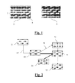
figure 1 représente une carte à puce selon l'invention - La
figure 2 représente les flux d'énergie et d'informations entre les différents modules qui composent un dispositif selon l'invention - La
figure 3 illustre une mise en oeuvre de l'invention avec un ordinateur.
- The
figure 1 represents a smart card according to the invention - The
figure 2 represents the flow of energy and information between the different modules that make up a device according to the invention - The
figure 3 illustrates an implementation of the invention with a computer.
Dans la suite de la description, un dispositif selon l'invention sera illustré par une carte à puce. Ce choix est uniquement indicatif et nullement limitatif, l'invention s'adaptant à tout dispositif électronique portable, et notamment les dispositifs électroniques dépourvus d'alimentation électrique propre, tels que les cartes à puces, les dongles USB, etc...In the following description, a device according to the invention will be illustrated by a smart card. This choice is only indicative and not limiting, the invention adapting to any portable electronic device, including electronic devices without a clean power supply, such as smart cards, USB dongles, etc ...
Dans la
Cet écran est donc un moyen parmi d'autres de réaliser cette restitution. N'importe quel moyen apte à diffuser une information peut lui être substitué, notamment un émetteur audio phonique.This screen is one way among others to achieve this restitution. Any means capable of broadcasting information may be substituted for it, in particular a sound audio transmitter.
Sur la face postérieure 2 de la carte, nous pouvons voir un ensemble de capteurs photosensibles. Ces capteurs photosensibles peuvent servir indifféremment à la production d'énergie, ou à la réception d'information par la carte.On the
L'organisation d'un dispositif selon l'invention est décrite dans la
Les boites représentées dans cette figure sont des boites fonctionnelles. C e s fonctionnalités peuvent être réalisées par des éléments physiques communs ou distincts.The boxes represented in this figure are functional boxes. These features can be realized by common or distinct physical elements.
Les capteurs photosensibles 11, reçoivent de l'énergie lumineuse. Cette énergie est convertie en énergie électrique que nous appellerons ici signal 17. Ce signal est dirigé vers une unité de pilotage 10. Cette unité de pilotage a pour fonction d'orienter tout ou partie du signal, vers le circuit d' alimentation 13, ou vers l'unité de traitement 14.The
L'unité de pilotage 10 est apte à sélectionner le signal issu de chaque cellule, ou groupe de cellules photosensibles 11. Chacun de ces sous-signaux est redirigé par l'unité de pilotage vers le circuit d'alimentation, ou bien l'unité de traitement.The
Dans un mode préféré d'implémentation de l'invention, l'unité de pilotage fonctionne avec un ensemble de règles décisionnelles, définissant quels sous-signaux doivent être redirigés vers le circuit d'alimentation, et quels doivent être dirigés vers l'unité de traitement.In a preferred embodiment of the invention, the control unit operates with a set of decision rules, defining which sub-signals must be redirected to the power supply circuit, and which must be directed to the control unit. treatment.
Il devient ainsi possible, en illuminant les capteurs 11 de manière sélectives, d'alimenter l'unité de traitement, et de lui transmettre de l'information. Les règles décisionnelles peuvent être construites de manière à ce que, en fonction de critères prédéfinis, la destination des sous-signaux changent. Ainsi lors du démarrage de la carte, l'ensemble des sous-signaux peut être dirigé vers le circuit d'alimentation afin de produire un maximum d'énergie. Dans une phase ultérieure, la carte peut recevoir des informations de l'extérieur, et auquel cas les sous-signaux issus d'une zone prédéfinie des capteurs 11 vont être dirigés vers l'unité de traitement. Une fois ces données reçues, et afin de permettre leur traitement, un maximum de sous-signaux peut être de nouveaux orientés vers le circuit d'alimentation.It thus becomes possible, by illuminating the
Les règles décisionnelles peuvent avantageusement être mises à jour, par exemple au travers des informations reçues via les capteurs 11.The decision rules can advantageously be updated, for example through the information received via the
Dans le cas ou la carte est munie d'un écran 12, les informations à afficher vont être envoyées par l'unité de traitement 14, mais l'énergie électrique nécessaire à l'affichage va être fournie par l'unité d'alimentation 13.In the case where the card is provided with a
La
En effet, pour illuminer les capteurs 11, et notamment fournir tant de l'énergie que de l'information, il faut un système d'illumination adapté.Indeed, to illuminate the
L'invention prévoit l'usage d'un écran 23, ainsi que d'un programme informatique adapté. Ces deux éléments seront ici représentés par un ordinateur à titre d'exemple.The invention provides for the use of a
Ainsi, le programme d'ordinateur peut définir une zone très précise de l'écran sur laquelle la carte doit être présentée. Cette zone peut ainsi être illuminée sélectivement afin de fournir à la carte l'énergie nécessaire à son fonctionnement ainsi que les informations dont elle a besoin.Thus, the computer program can define a very precise area of the screen on which the map is to be presented. This area can be illuminated selectively to provide the card with the energy necessary for its operation and the information it needs.
Une implémentation particulièrement intéressante de l'invention comporte une carte bancaire selon l'invention, ainsi que le site web de la banque correspondante affiché à l'écran de l'ordinateur. Avant de pouvoir faire un paiement en ligne, l'utilisateur s'identifie sur le site web, et pose sa carte contre l'écran, dans le cadre affiché à cet effet. Le serveur de la banque envoie à la carte un aléa, la carte traite celui-ci, et produit un numéro unique de transaction, qui est affiché sur l'écran. Les ressources de la carte ont ainsi pu être utilisées, en adéquation avec des informations issues directement de la banque, sans que l'utilisateur n'ait besoin de posséder de lecteur spécifique.A particularly interesting implementation of the invention comprises a bank card according to the invention, as well as the website of the corresponding bank displayed on the screen of the computer. Before being able to make a payment online, the user identifies himself on the website, and puts his card against the screen, in the frame posted for this purpose. The bank server sends the card a hazard, the card processes it, and produces a unique transaction number, which is displayed on the screen. The resources of the card could thus be used, in adequacy with information directly from the bank, without the user needing to have a specific reader.
Claims (9)
Priority Applications (2)
| Application Number | Priority Date | Filing Date | Title |
|---|---|---|---|
| EP10305549A EP2391034A1 (en) | 2010-05-25 | 2010-05-25 | Light-communicating passive device |
| PCT/EP2011/057509 WO2011147680A1 (en) | 2010-05-25 | 2011-05-10 | Lumino‑communicating passive device |
Applications Claiming Priority (1)
| Application Number | Priority Date | Filing Date | Title |
|---|---|---|---|
| EP10305549A EP2391034A1 (en) | 2010-05-25 | 2010-05-25 | Light-communicating passive device |
Publications (1)
| Publication Number | Publication Date |
|---|---|
| EP2391034A1 true EP2391034A1 (en) | 2011-11-30 |
Family
ID=43259818
Family Applications (1)
| Application Number | Title | Priority Date | Filing Date |
|---|---|---|---|
| EP10305549A Withdrawn EP2391034A1 (en) | 2010-05-25 | 2010-05-25 | Light-communicating passive device |
Country Status (2)
| Country | Link |
|---|---|
| EP (1) | EP2391034A1 (en) |
| WO (1) | WO2011147680A1 (en) |
Citations (8)
| Publication number | Priority date | Publication date | Assignee | Title |
|---|---|---|---|---|
| EP0498582A2 (en) * | 1991-01-31 | 1992-08-12 | Nec Corporation | IC card information read/write system |
| US5635915A (en) * | 1989-04-18 | 1997-06-03 | Ilid Pty. Ltd. | Transmission system |
| US5861817A (en) * | 1997-07-02 | 1999-01-19 | Douglas A. Palmer | System for, and method of, displaying prices on tags in supermarkets |
| WO2000021020A2 (en) * | 1998-10-02 | 2000-04-13 | Comsense Technologies, Ltd. | Card for interaction with a computer |
| EP1211841A1 (en) * | 2000-06-23 | 2002-06-05 | Esignus, S.L. | External signature device for a pc with optical data input via the monitor |
| WO2002065391A1 (en) * | 2001-02-15 | 2002-08-22 | Optisign Ltd. | Smart card having an optical communication circuit and a method for use thereof |
| US20040044709A1 (en) * | 2002-09-03 | 2004-03-04 | Florencio Cabrera | System and method for optical data communication |
| EP2120373A1 (en) * | 2007-03-13 | 2009-11-18 | Kabushiki Kaisha Toshiba | Receiving device for visible light communication, and visible light communication system |
-
2010
- 2010-05-25 EP EP10305549A patent/EP2391034A1/en not_active Withdrawn
-
2011
- 2011-05-10 WO PCT/EP2011/057509 patent/WO2011147680A1/en active Application Filing
Patent Citations (8)
| Publication number | Priority date | Publication date | Assignee | Title |
|---|---|---|---|---|
| US5635915A (en) * | 1989-04-18 | 1997-06-03 | Ilid Pty. Ltd. | Transmission system |
| EP0498582A2 (en) * | 1991-01-31 | 1992-08-12 | Nec Corporation | IC card information read/write system |
| US5861817A (en) * | 1997-07-02 | 1999-01-19 | Douglas A. Palmer | System for, and method of, displaying prices on tags in supermarkets |
| WO2000021020A2 (en) * | 1998-10-02 | 2000-04-13 | Comsense Technologies, Ltd. | Card for interaction with a computer |
| EP1211841A1 (en) * | 2000-06-23 | 2002-06-05 | Esignus, S.L. | External signature device for a pc with optical data input via the monitor |
| WO2002065391A1 (en) * | 2001-02-15 | 2002-08-22 | Optisign Ltd. | Smart card having an optical communication circuit and a method for use thereof |
| US20040044709A1 (en) * | 2002-09-03 | 2004-03-04 | Florencio Cabrera | System and method for optical data communication |
| EP2120373A1 (en) * | 2007-03-13 | 2009-11-18 | Kabushiki Kaisha Toshiba | Receiving device for visible light communication, and visible light communication system |
Also Published As
| Publication number | Publication date |
|---|---|
| WO2011147680A1 (en) | 2011-12-01 |
Similar Documents
| Publication | Publication Date | Title |
|---|---|---|
| CN112672176B (en) | Interaction method, device, terminal, server and medium based on virtual resources | |
| FR3051581A1 (en) | DEVICE FOR GENERATING AND DYNAMIC SECURITY CODE DISPLAY | |
| US9619195B2 (en) | Invisible light transmission via a display assembly | |
| CN110570180A (en) | User device enabling access to payment information in response to mechanical input detection | |
| CN110585726A (en) | User recall method, device, server and computer readable storage medium | |
| FR2798809A1 (en) | APPARATUS AND METHOD FOR TRANSFERRING DATA | |
| WO1997007448A2 (en) | Conditional access method and device | |
| CN109144346B (en) | Song sharing method and device and storage medium | |
| US20200105851A1 (en) | Ambient light sensing display assemblies | |
| FR2861193A1 (en) | SYSTEM AND METHOD FOR SUPPORTING DVI NATIVE DIGITAL VIDEO INTERFACE OR HOST STATION | |
| CA2676236C (en) | Portable authentication device | |
| CN110890969B (en) | Method and device for mass-sending message, electronic equipment and storage medium | |
| CN110503416B (en) | Numerical value transfer method, device, computer equipment and storage medium | |
| FR2953966A1 (en) | ELECTRONIC SHELT LABEL SYSTEM HAVING AN ALARM FUNCTION BASED ON MAGNETIC FIELD DETECTION | |
| CN111275497A (en) | Interaction method and device based on reward data, computer equipment and storage medium | |
| CN113506086A (en) | Task issuing method and device, computer equipment and medium | |
| EP2569735B1 (en) | Payment card comprising an electronic game chip | |
| EP2610717A1 (en) | Communication device for equipment including a touch screen, communication system | |
| EP2391034A1 (en) | Light-communicating passive device | |
| US8405829B2 (en) | Portable electronic device and method for testing polarizing ability of glass using the same | |
| KR20100050201A (en) | Touch pad and mobile terminal having the same | |
| EP3594880A1 (en) | Method for secured cryptographic data transmission | |
| FR3047583A1 (en) | METHOD OF SECURELY TRANSMITTING AUTHENTICATION INFORMATION BETWEEN SOFTWARE APPLICATIONS IN A COMPUTER TERMINAL | |
| CN110808985B (en) | Song on-demand method, device, terminal, server and storage medium | |
| CN112311652A (en) | Message sending method, device, terminal and storage medium |
Legal Events
| Date | Code | Title | Description |
|---|---|---|---|
| AK | Designated contracting states |
Kind code of ref document: A1 Designated state(s): AL AT BE BG CH CY CZ DE DK EE ES FI FR GB GR HR HU IE IS IT LI LT LU LV MC MK MT NL NO PL PT RO SE SI SK SM TR |
|
| AX | Request for extension of the european patent |
Extension state: BA ME RS |
|
| PUAI | Public reference made under article 153(3) epc to a published international application that has entered the european phase |
Free format text: ORIGINAL CODE: 0009012 |
|
| STAA | Information on the status of an ep patent application or granted ep patent |
Free format text: STATUS: THE APPLICATION IS DEEMED TO BE WITHDRAWN |
|
| 18D | Application deemed to be withdrawn |
Effective date: 20120531 |