EP2390966B1 - Connector - Google Patents
Connector Download PDFInfo
- Publication number
- EP2390966B1 EP2390966B1 EP11167793.6A EP11167793A EP2390966B1 EP 2390966 B1 EP2390966 B1 EP 2390966B1 EP 11167793 A EP11167793 A EP 11167793A EP 2390966 B1 EP2390966 B1 EP 2390966B1
- Authority
- EP
- European Patent Office
- Prior art keywords
- connector
- holder
- peripheral surface
- female
- engaging
- Prior art date
- Legal status (The legal status is an assumption and is not a legal conclusion. Google has not performed a legal analysis and makes no representation as to the accuracy of the status listed.)
- Not-in-force
Links
Images


Classifications
-
- H—ELECTRICITY
- H01—ELECTRIC ELEMENTS
- H01R—ELECTRICALLY-CONDUCTIVE CONNECTIONS; STRUCTURAL ASSOCIATIONS OF A PLURALITY OF MUTUALLY-INSULATED ELECTRICAL CONNECTING ELEMENTS; COUPLING DEVICES; CURRENT COLLECTORS
- H01R13/00—Details of coupling devices of the kinds covered by groups H01R12/70 or H01R24/00 - H01R33/00
- H01R13/62—Means for facilitating engagement or disengagement of coupling parts or for holding them in engagement
- H01R13/623—Casing or ring with helicoidal groove
-
- H—ELECTRICITY
- H01—ELECTRIC ELEMENTS
- H01R—ELECTRICALLY-CONDUCTIVE CONNECTIONS; STRUCTURAL ASSOCIATIONS OF A PLURALITY OF MUTUALLY-INSULATED ELECTRICAL CONNECTING ELEMENTS; COUPLING DEVICES; CURRENT COLLECTORS
- H01R13/00—Details of coupling devices of the kinds covered by groups H01R12/70 or H01R24/00 - H01R33/00
- H01R13/62—Means for facilitating engagement or disengagement of coupling parts or for holding them in engagement
- H01R13/625—Casing or ring with bayonet engagement
Definitions
- the present invention relates to a connector that can be connected in, for example, both the bayonet-type and the screw-type method.
- a male connector 100 with an electric cable on one end includes a knob portion 101 with male threads 101a and sliding grooves 101b formed on the outer peripheral surface thereof; and a retaining hardware 102, with engaging protruding portions 102b, having engaging hooks 102a at the tip end side thereof, that slide forward and backward in the sliding grooves 101b formed therein. Additionally, the retaining hardware 102 is biased towards the knob portion 101 by a coil spring that is attached there behind (See, for example, Japanese Unexamined Patent Application Publication 2007-103046 (“JP '046”)).
- a bayonet-type female connector with an electric cable on one end thereof comprises: a knob portion, wherein engaging grooves are formed on the inner peripheral surface thereof is provided with guiding portions, for guiding engaging hooks 102a, and stopper portions for engaging the engaging hook 102a when attaching the male connector 100.
- the operator holds the knob portion 101 of the male connector 100 and the knob portion of the female connector, and inserts the male connector 100 into the female connector to insert the engaging hooks 102a along the guide portions of the engaging grooves.
- the male connector 100 or the female connector is rotated in a specific direction to cause the engaging hooks 102a to engage with the stopper portions of the engaging grooves. Doing so makes it possible to electrically connect electric cables coaxially.
- a knob portion is provided wherein female threads for screwing onto the male threads 101a are formed on the inner peripheral surface.
- the operator holds the knob portion 101 of the male connector 100 and the knob portion of the female connector, and screws the male threads 101a together with the female threads.
- the engaging hooks 102a are moved towards the rear, while being biased by the coil spring 103, through the contact with the female threads. Doing so makes it possible to electrically connect electric cables coaxially.
- a coil spring 103 is necessary in order to bias the retaining hardware 102 towards the knob portion 101 side in order to connect to both the female connector of the screw-type and the bayonet-type.
- problems may be caused by the inoperability of the coil spring due to the break, and thus there is a problem in that there are concerns that the connection with the connector might become impossible.
- even if there is just corrosion that is not to the extent that the coil spring 103 breaks still there are problems that may be caused due to the inoperable state of the coil spring 103 caused by the corrosion, and thus there are problems in that there are concerns that it may become impossible to connect the connector.
- the present invention was created in order to solve the problem areas set forth above, and the object thereof is to provide a connector that can connect to both the bayonet type and the screw type, without the use of a coil spring.
- the connector as set forth in the present invention is a connector for connecting electrically between lines by connecting a male connector having a plug main unit portion having a line to a female connector having a socket main unit portion having a line; wherein: the male connector includes a holder that is attached rotatably to the outer peripheral surface of the plug main unit portion, with male threads formed on the outer peripheral surface thereof, with sliding grooves formed with specific spacing on the rearward side of the outer peripheral surface; and a knob portion, formed integrally with engaging protruding portions that have engaging hooks on the tip end sides thereof, and that slide in the sliding grooves, attached so as to be able to rotate together with the holder.
- the present invention structured as set forth above, enables the attachment to female connectors of both the bayonet-type and the screw-type without the use of a coil spring, through the provision of a holder wherein the female threads and sliding grooves are formed on the outer peripheral surface thereof, and a knob portion that is formed integrally with engaging protruding portions that have engaging hooks on the tip end sides thereof and that slide in the sliding grooves.
- FIG. 1 is a perspective view illustrating the structure of a connector according to an example of the present invention.
- FIG. 2 is a perspective assembly diagram illustrating the structure of a holder 6 and a knob portion 7 according to the present invention.
- the connector is structured from a male connector 1, having an electric cable (line) 3a on one end side thereof, and a female connector 2, having an electric cable (line) 3b on one end side thereof.
- the male connector 1, as illustrated in FIG. 1 is structured from a plug main unit portion 5 having a pin terminal 4 that is electrically connected to an end portion of an electric cable 3a protruding therefrom, a holder 6 that is attached rotatably to the outer peripheral surface of the plug main unit portion 5, a knob portion 7 that is attached so as to be able to rotate together with the holder 6, and a plug outer covering portion 8.
- the holder 6 is an annular member, and, as illustrated in FIG. 2 , male threads 9, for securing together with female threads 18 of a screw-type female connector 2b, described below, are formed on the outer peripheral surface thereof. Moreover, sliding grooves 10, wherein engaging protruding portions 12, described below, of the knob portion 7 slide, are formed at specific intervals, parallel to the axis. Note that the sliding grooves 10 are formed as cutaway portions so as to pass through to reach the inner peripheral surface side of the holder 6. Moreover, on the forward side of the sliding groove 10 part of the outer peripheral surface of the holder 6, guide thread portions 11 are formed for guiding, to the male thread 9 side, the female threads 18 of the screw-type female connector 2b.
- the knob portion 7 is the part that is held by the operator when attaching the male connector 1 to the female connector 2, and, as illustrated in FIG. 2 , is formed integrally with the engaging protruding portions 12.
- the engaging protruding portions 12 are formed in parallel with the axis at identical intervals as the sliding grooves 10, and engaging hooks 13, for engaging the engaging grooves 17 of the bayonet-type female connector 2a are formed on the tip end sides thereof.
- the inner diameter of the knob portion 7 is formed to be essentially the same dimension as the outer diameter of the holder 6.
- FIG. 3 (a) is a perspective diagram
- FIG. 3 (b) is a partial cutaway perspective diagram, of the case wherein the male connector according to the example is connected to a bayonet-type female connector.
- the bayonet-type female connector 2a as illustrated in FIG. 1 and FIG.
- socket main unit portion 14 that connects electrically, coaxially, the electric cables 3a and 3b, through the pin terminal 4 when connected to the male connector 1, a knob portion 15 that is attached rotatably to the outer peripheral surface of the socket main unit portion 14, and a socket outer covering portion 16.
- engaging grooves 17, made from guide portions 17a that guide the engaging hooks 13 when the male connector 1 is attached to a bayonet-type female connector 2a, and stopper portions 17b that engage the engaging hooks 13, are formed on the inner peripheral surface of the knob portion 15.
- the male connector 1 or the female connector 2a is rotated to one side to cause the engaging hooks 13 to engage with the stopper portions 17b. Doing so causes the male connector 1 and the bayonet-type female connector 2a to go into a locked state, thereby electrically connecting the electric cables 3a and 3b coaxially.
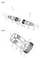
- FIG. 4(a) is a perspective diagram and FIG. 4 (b) is a partial cutaway perspective diagram, of the case wherein the male connector according to the present invention is connected to a screw-type female connector.
- the screw-type female connector 2b as illustrated in FIG. 4 (b) has female threads 18 for screwing together with the male threads 9, formed on the inner peripheral surface of the knob portion 15, instead of the engaging grooves 17 of the bayonet-type female connector 2a.
- the other structures are identical, so identical codes are assigned thereto and explanations thereof are omitted.
- the structure is such that the male threads 9 and the sliding grooves 10 are formed in the holder 6 and the engaging protruding portions 12, having the engaging hooks 13, are formed integrally with the knob portion 7, and thus, for a bayonet-type female connector 2a, the operator makes the connection while pushing the engaging hooks 13 towards the holder 6 side by the knob portion 7, while for the screw-type female connector 2b, the operator makes the connection by separating the holder 6 from the knob portion 7 through the female threads 18 pushing against the engaging hooks 13, so that the engaging hooks 13 are moved towards the rearward side, and thus the male connection 1 can be connected to female connectors 2 of both the bayonet type and the screw type, without the use of a coil spring as in the conventional connector.
- the number of parts is reduced because the coil spring is unnecessary, making it possible to reduce parts costs. Furthermore, because when manufacturing a conventional male connector that uses the coil spring it is necessary to form an outer coating portion for the plug by attaching to a die while pushing the coil spring, contained therein, towards the holder side when forming the plug outer coating after the coil spring is put into the holder, the manufacturing was difficult. In contrast, with the male connector according to the example, the coil spring is not used, and thus the manufacturing is easy, enabling a reduction in manufacturing cost.
- the guide thread portion 11 for guiding the female threads 18 to the male thread 9 side is formed on the outer peripheral surface of the holder 6, the male threads 9 and the female threads 18 can be screwed together easily when connecting the male connector 1 to the screw-type female connector 2b.
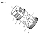
- the structure may be one as illustrated in FIG. 5 , wherein a dummy knob portion 19 that contacts the knob portion 7 when the engaging protruding portions 12 are positioned at the tip end of the sliding grooves 10 is formed on the outer peripheral surface of the holder 6. Forming the dummy knob portion 19 in this way enables the spacing between the knob portion 7 and the holder 6 to be made visibly shorter when the male connector 1 is connected to a screw-type female connector 2b, making it possible for the operator to sense more easily when the connection is completed.
- the sliding grooves 10 were formed as cutaway portions that pass through to the inner peripheral surface of the holder 6.
- the sliding grooves 10 may be formed as recessed shapes that do not pass through to the inner peripheral surface of the holder 6.
Landscapes
- Details Of Connecting Devices For Male And Female Coupling (AREA)
- Connector Housings Or Holding Contact Members (AREA)
Description
- The present application claims priority to Japanese Patent Application No.
2010-122927, filed May 28, 2010 - The present invention relates to a connector that can be connected in, for example, both the bayonet-type and the screw-type method.
- In conventional connectors, a
male connector 100 with an electric cable on one end, as illustrated inFIGS. 6 (a) and 6 (b) , includes aknob portion 101 withmale threads 101a and slidinggrooves 101b formed on the outer peripheral surface thereof; and aretaining hardware 102, with engaging protrudingportions 102b, having engaginghooks 102a at the tip end side thereof, that slide forward and backward in thesliding grooves 101b formed therein. Additionally, theretaining hardware 102 is biased towards theknob portion 101 by a coil spring that is attached there behind (See, for example, Japanese Unexamined Patent Application Publication2007-103046 - Additionally, in a bayonet-type female connector with an electric cable on one end thereof, comprises: a knob portion, wherein engaging grooves are formed on the inner peripheral surface thereof is provided with guiding portions, for guiding
engaging hooks 102a, and stopper portions for engaging theengaging hook 102a when attaching themale connector 100. When themale connector 100 is attached to this bayonet-type female connector, the operator holds theknob portion 101 of themale connector 100 and the knob portion of the female connector, and inserts themale connector 100 into the female connector to insert theengaging hooks 102a along the guide portions of the engaging grooves. Following this, themale connector 100 or the female connector is rotated in a specific direction to cause theengaging hooks 102a to engage with the stopper portions of the engaging grooves. Doing so makes it possible to electrically connect electric cables coaxially. - On the other hand, in the screw-type female connector with an electric cable on one end thereof, a knob portion is provided wherein female threads for screwing onto the
male threads 101a are formed on the inner peripheral surface. When connecting themale connector 100 to this screw-type female connector, the operator holds theknob portion 101 of themale connector 100 and the knob portion of the female connector, and screws themale threads 101a together with the female threads. At this time, theengaging hooks 102a are moved towards the rear, while being biased by thecoil spring 103, through the contact with the female threads. Doing so makes it possible to electrically connect electric cables coaxially. - In the conventional male connector as disclosed in JP '046, a
coil spring 103 is necessary in order to bias theretaining hardware 102 towards theknob portion 101 side in order to connect to both the female connector of the screw-type and the bayonet-type. However, when thecoil spring 103 is broken, problems may be caused by the inoperability of the coil spring due to the break, and thus there is a problem in that there are concerns that the connection with the connector might become impossible. Moreover, even if there is just corrosion that is not to the extent that thecoil spring 103 breaks, still there are problems that may be caused due to the inoperable state of thecoil spring 103 caused by the corrosion, and thus there are problems in that there are concerns that it may become impossible to connect the connector. - The present invention was created in order to solve the problem areas set forth above, and the object thereof is to provide a connector that can connect to both the bayonet type and the screw type, without the use of a coil spring.
- The connector as set forth in the present invention is a connector for connecting electrically between lines by connecting a male connector having a plug main unit portion having a line to a female connector having a socket main unit portion having a line; wherein: the male connector includes a holder that is attached rotatably to the outer peripheral surface of the plug main unit portion, with male threads formed on the outer peripheral surface thereof, with sliding grooves formed with specific spacing on the rearward side of the outer peripheral surface; and a knob portion, formed integrally with engaging protruding portions that have engaging hooks on the tip end sides thereof, and that slide in the sliding grooves, attached so as to be able to rotate together with the holder.
- The present invention, structured as set forth above, enables the attachment to female connectors of both the bayonet-type and the screw-type without the use of a coil spring, through the provision of a holder wherein the female threads and sliding grooves are formed on the outer peripheral surface thereof, and a knob portion that is formed integrally with engaging protruding portions that have engaging hooks on the tip end sides thereof and that slide in the sliding grooves.
- Further advantages, features, aspects and details are evident from the dependent claims, the description and the drawings.
- So that the manner in which the above recited features of the present invention can be understood in detail, a more particular description of the invention, briefly summarized above, is described by reference to embodiments. The accompanying drawings relate to embodiments of the invention and are described in the following:
-
FIG. 1 is a perspective view illustrating the structure of a connector according to an example of the present invention. -
FIG. 2 is a perspective assembly diagram illustrating the structure of the holder and a knob portion according to the example according to the present invention. -
FIG. 3 (a) is a perspective diagram andFIG. 3 (b) is a partial cutaway perspective diagram, of the case wherein the male connector according to the present invention is connected to a bayonet-type female connector. -
FIG. 4 (a) is a perspective diagram andFIG. 4 (b) is a partial cutaway perspective diagram, of the case wherein the male connector according to the present invention is connected to a screw-type female connector. -
FIG. 5 is a perspective assembly diagram illustrating the structure of the holder and a knob portion according to another example of the present invention. -
FIG. 6 (a) is a perspective assembly diagram andFIG. 6 (b) is a sectional perspective diagram, illustrating the structure of a conventional male connector. - Examples according to the present invention are explained in detail below, referencing the drawings.
-
Fig. 1 is a perspective view illustrating the structure of a connector according to an example of the present invention.FIG. 2 is a perspective assembly diagram illustrating the structure of a holder 6 and aknob portion 7 according to the present invention. As illustrated inFIG. 1 , the connector is structured from a male connector 1, having an electric cable (line) 3a on one end side thereof, and afemale connector 2, having an electric cable (line) 3b on one end side thereof. - The male connector 1, as illustrated in
FIG. 1 , is structured from a plugmain unit portion 5 having a pin terminal 4 that is electrically connected to an end portion of anelectric cable 3a protruding therefrom, a holder 6 that is attached rotatably to the outer peripheral surface of the plugmain unit portion 5, aknob portion 7 that is attached so as to be able to rotate together with the holder 6, and a plugouter covering portion 8. - The holder 6 is an annular member, and, as illustrated in
FIG. 2 , male threads 9, for securing together withfemale threads 18 of a screw-typefemale connector 2b, described below, are formed on the outer peripheral surface thereof. Moreover, slidinggrooves 10, wherein engaging protrudingportions 12, described below, of theknob portion 7 slide, are formed at specific intervals, parallel to the axis. Note that thesliding grooves 10 are formed as cutaway portions so as to pass through to reach the inner peripheral surface side of the holder 6. Moreover, on the forward side of thesliding groove 10 part of the outer peripheral surface of the holder 6,guide thread portions 11 are formed for guiding, to the male thread 9 side, thefemale threads 18 of the screw-typefemale connector 2b. - The
knob portion 7 is the part that is held by the operator when attaching the male connector 1 to thefemale connector 2, and, as illustrated inFIG. 2 , is formed integrally with the engagingprotruding portions 12. The engaging protrudingportions 12 are formed in parallel with the axis at identical intervals as thesliding grooves 10, and engaginghooks 13, for engaging theengaging grooves 17 of the bayonet-type female connector 2a are formed on the tip end sides thereof. Note that the inner diameter of theknob portion 7 is formed to be essentially the same dimension as the outer diameter of the holder 6. - The structure of the bayonet-type female connector 2a is explained next. Note that "bayonet-type" indicates the type wherein the connection is made by a plurality of connecting hocks and stopper portions that engage the engaging hooks.
FIG. 3 (a) is a perspective diagram andFIG. 3 (b) is a partial cutaway perspective diagram, of the case wherein the male connector according to the example is connected to a bayonet-type female connector. The bayonet-type female connector 2a, as illustrated inFIG. 1 andFIG. 3 , is structured from a socketmain unit portion 14 that connects electrically, coaxially, theelectric cables knob portion 15 that is attached rotatably to the outer peripheral surface of the socketmain unit portion 14, and a socketouter covering portion 16. - As illustrated in
FIG. 3 (b) , engaginggrooves 17, made fromguide portions 17a that guide theengaging hooks 13 when the male connector 1 is attached to a bayonet-type female connector 2a, and stopperportions 17b that engage theengaging hooks 13, are formed on the inner peripheral surface of theknob portion 15. - The operation when the male connector 1 is attached to the bayonet-type female connector 2a will be explained next. When the male connector 1 is attached to the bayonet-type female connector 2a, first, as illustrated in
FIG. 3 , the operator holds theknob portions knob portion 7 towards the holder 6 side. Doing so causes theengaging hooks 13 to be inserted along theguide portions 17a. - Following this, the male connector 1 or the female connector 2a is rotated to one side to cause the
engaging hooks 13 to engage with thestopper portions 17b. Doing so causes the male connector 1 and the bayonet-type female connector 2a to go into a locked state, thereby electrically connecting theelectric cables - The structure of the screw-type
female connector 2b will be explained next.FIG. 4(a) is a perspective diagram andFIG. 4 (b) is a partial cutaway perspective diagram, of the case wherein the male connector according to the present invention is connected to a screw-type female connector. The screw-typefemale connector 2b, as illustrated inFIG. 4 (b) hasfemale threads 18 for screwing together with the male threads 9, formed on the inner peripheral surface of theknob portion 15, instead of theengaging grooves 17 of the bayonet-type female connector 2a. The other structures are identical, so identical codes are assigned thereto and explanations thereof are omitted. - The operation when connecting the male connector 1 to a screw-type
female connector 2b is explained next. When the male connector 1 is connected to the screw-type thefemale connector 2b, first, as illustrated inFIG. 4 , the operator holds theknob portions guide thread portions 11 and thefemale threads 18 together. Doing so causes thefemale threads 18 to be guided to the male threads 9. When thefemale threads 18 contact theengaging hooks 13, theengaging hooks 13 are biased towards the rearward side, and theknob portion 7 separates from the holder 6. Following this, the male threads 9 and thefemale threads 18 are screwed together. This causes the male connector 1 and the screw-typefemale connector 2b to go into the locked state, to connect electrically theelectric cables - As described above, in this example, the structure is such that the male threads 9 and the sliding
grooves 10 are formed in the holder 6 and the engaging protrudingportions 12, having the engaginghooks 13, are formed integrally with theknob portion 7, and thus, for a bayonet-type female connector 2a, the operator makes the connection while pushing the engaginghooks 13 towards the holder 6 side by theknob portion 7, while for the screw-typefemale connector 2b, the operator makes the connection by separating the holder 6 from theknob portion 7 through thefemale threads 18 pushing against the engaginghooks 13, so that the engaginghooks 13 are moved towards the rearward side, and thus the male connection 1 can be connected tofemale connectors 2 of both the bayonet type and the screw type, without the use of a coil spring as in the conventional connector. - Additionally, the number of parts is reduced because the coil spring is unnecessary, making it possible to reduce parts costs. Furthermore, because when manufacturing a conventional male connector that uses the coil spring it is necessary to form an outer coating portion for the plug by attaching to a die while pushing the coil spring, contained therein, towards the holder side when forming the plug outer coating after the coil spring is put into the holder, the manufacturing was difficult. In contrast, with the male connector according to the example, the coil spring is not used, and thus the manufacturing is easy, enabling a reduction in manufacturing cost.
- Additionally, because the
guide thread portion 11 for guiding thefemale threads 18 to the male thread 9 side is formed on the outer peripheral surface of the holder 6, the male threads 9 and thefemale threads 18 can be screwed together easily when connecting the male connector 1 to the screw-typefemale connector 2b. - In the above example, there is a danger that when the male connector 1 is connected to a screw-type
female connector 2b, theknob portion 7 may become separated from the holder 6, so that the operator will not be able to tell that the connection has been completed. Given this, the structure may be one as illustrated inFIG. 5 , wherein adummy knob portion 19 that contacts theknob portion 7 when the engaging protrudingportions 12 are positioned at the tip end of the slidinggrooves 10 is formed on the outer peripheral surface of the holder 6. Forming thedummy knob portion 19 in this way enables the spacing between theknob portion 7 and the holder 6 to be made visibly shorter when the male connector 1 is connected to a screw-typefemale connector 2b, making it possible for the operator to sense more easily when the connection is completed. - Note, in the male connectors 1 in the above examples the sliding
grooves 10 were formed as cutaway portions that pass through to the inner peripheral surface of the holder 6. Alternately, the slidinggrooves 10 may be formed as recessed shapes that do not pass through to the inner peripheral surface of the holder 6.
Claims (7)
- A connector connecting electrically between lines by connecting a male connector (1) comprising a plug main unit portion having a line to a female connector (2) comprising a socket main unit portion (14) having a line; wherein:the male connector comprises:a holder (6) attached rotatably to an outer peripheral surface of the plug main unit portion (5), comprising:male threads (9) formed on an outer peripheral surface of the holder; andsliding grooves formed with predetermined spacing on a rearward side of the outer peripheral surface of the holder; anda knob portion (7), formed integrally with engaging protruding portions (12) having engaging hooks (13) on tip end sides of the engaging protruding portions, and that slide in the sliding grooves (10), attached to rotate together with the holder.
- The connector as set forth in Claim 1, wherein the female connector comprises:a female holder, attached rotatably to an outer peripheral surface of the socket main unit portion, having:an engaging groove (17) engaging the engaging hook (13), formed on an inner peripheral surface of the female holder.
- The connector as set forth in Claim 1 or 2, wherein the female connector comprises:a female holder, attached rotatably to the outer peripheral surface of the socket main unit portion, having:female threads (18) screwing together with the male threads (9), formed on the inner peripheral surface of the female holder.
- The connector as set forth in any of the Claims 1 to 3, further comprising:a guide thread portion (11) formed at a rearward side of the sliding groove part on the outer peripheral surface of the holder of the male connector.
- The connector as set forth in any of the Claims 1 to 4, wherein:the sliding grooves (10) are cut away so as to pass through to the inner peripheral surface of the holder.
- The connector as set forth in any of the Claims 1 to 5, wherein:the sliding groove is a recessed shape that prevents pass through to the inner peripheral surface of the holder.
- The connector as set forth in any of the Claims 1 to 6, further comprising:a dummy knob portion (19) that contacts the knob portion when the engaging hooks are positioned at the tip end of the sliding grooves formed on the outer peripheral surface of the holder of the male connector.
Applications Claiming Priority (1)
| Application Number | Priority Date | Filing Date | Title |
|---|---|---|---|
| JP2010122927A JP5449033B2 (en) | 2010-05-28 | 2010-05-28 | connector |
Publications (3)
| Publication Number | Publication Date |
|---|---|
| EP2390966A2 EP2390966A2 (en) | 2011-11-30 |
| EP2390966A3 EP2390966A3 (en) | 2013-03-06 |
| EP2390966B1 true EP2390966B1 (en) | 2014-03-26 |
Family
ID=44483904
Family Applications (1)
| Application Number | Title | Priority Date | Filing Date |
|---|---|---|---|
| EP11167793.6A Not-in-force EP2390966B1 (en) | 2010-05-28 | 2011-05-27 | Connector |
Country Status (4)
| Country | Link |
|---|---|
| US (1) | US8192218B2 (en) |
| EP (1) | EP2390966B1 (en) |
| JP (1) | JP5449033B2 (en) |
| CN (1) | CN102299448B (en) |
Families Citing this family (23)
| Publication number | Priority date | Publication date | Assignee | Title |
|---|---|---|---|---|
| CN102593620B (en) * | 2012-03-26 | 2014-11-19 | 安德鲁公司 | Fast self-lock thread coupling port connector mechanism |
| US9142914B2 (en) | 2012-10-19 | 2015-09-22 | Woodhead Industries, Inc. | Push lock electrical connector |
| US9397441B2 (en) * | 2013-03-15 | 2016-07-19 | Cinch Connections, Inc. | Connector with anti-decoupling mechanism |
| US9559459B2 (en) * | 2013-10-18 | 2017-01-31 | Woodhead Industries, Inc. | Push-lock electrical connector |
| US9477049B2 (en) * | 2013-12-20 | 2016-10-25 | Senko Advanced Components, Inc. | Lockable connectors and connection assemblies |
| US9385470B2 (en) * | 2014-04-17 | 2016-07-05 | Tyco Electronics Corporation | Connector having coupling mechanism |
| US9437965B2 (en) | 2014-04-17 | 2016-09-06 | Tyco Electronics Corporation | Connector having coupling mechanism |
| TWM491979U (en) * | 2014-07-03 | 2014-12-11 | T Conn Prec Corp | Switching structure of cable connector |
| CN104124577B (en) * | 2014-08-06 | 2016-08-24 | 厦门唯恩电气有限公司 | Electromagnetic shielding connector construction |
| CN104319495B (en) * | 2014-08-25 | 2017-03-22 | 中航光电科技股份有限公司 | Spring claw, array spring claw combination plughole contact piece and electric connector |
| JP6354949B2 (en) * | 2014-10-08 | 2018-07-11 | ティアック株式会社 | Connector structure |
| JP6331980B2 (en) * | 2014-11-06 | 2018-05-30 | 株式会社デンソー | Fuel supply device |
| CN105551661A (en) * | 2016-01-05 | 2016-05-04 | 成都远东高科科技有限公司 | Radio-frequency cable easy to install |
| USD833978S1 (en) | 2016-04-22 | 2018-11-20 | Westinghouse Air Brake Technologies Corporation | Rail car power connector |
| US10199766B2 (en) * | 2016-04-22 | 2019-02-05 | Westinghouse Air Brake Technologies Corporation | Breakaway railcar power connector |
| CN106549261B (en) * | 2016-10-20 | 2018-10-30 | 慈溪宏一电子有限公司 | A kind of socket and plug and charging connection system and the charging pile with the system |
| JP6772025B2 (en) | 2016-10-24 | 2020-10-21 | モレックス エルエルシー | connector |
| TWM539732U (en) * | 2016-11-24 | 2017-04-11 | Kunshan Amphenol Zhengri Electronics Co Ltd | Electrical connector |
| CN110197975B (en) * | 2018-02-27 | 2021-09-28 | 中航光电科技股份有限公司 | Connector assembly and connector thereof |
| US10790615B2 (en) * | 2018-12-28 | 2020-09-29 | Raytheon Company | Cable quick connector adapter |
| DE102019114262B3 (en) * | 2019-05-28 | 2020-11-05 | Amphenol Tuchel Industrial GmbH | Connector with locking system |
| TWI716194B (en) * | 2019-11-15 | 2021-01-11 | 大陸商昆山安費諾正日電子有限公司 | Connector with fast positioning structures |
| JP7512866B2 (en) * | 2020-11-26 | 2024-07-09 | オムロン株式会社 | connector |
Family Cites Families (24)
| Publication number | Priority date | Publication date | Assignee | Title |
|---|---|---|---|---|
| US2962688A (en) * | 1957-05-31 | 1960-11-29 | Siemens And Halske Ag Berlin A | Plug-in cable connector |
| US3039072A (en) * | 1958-07-11 | 1962-06-12 | Joy Mfg Co | Electrical connector |
| DE3022102C1 (en) * | 1980-06-12 | 1981-11-26 | Georg Dipl.-Ing. Dr.-Ing. 8152 Feldkirchen-Westerham Spinner | RF coaxial connector |
| US4521066A (en) * | 1984-04-02 | 1985-06-04 | The Deutsch Company, Electronic Components Division | Electrical connector with non-precockable coupling ring |
| US5108297A (en) * | 1990-11-26 | 1992-04-28 | Hubbell Incorporated | Positive locking electrical plug with shielded blade protection |
| ATE230523T1 (en) * | 1997-12-03 | 2003-01-15 | Palazzoli Spa | DEVICE FOR FIXING CABLES AT THE EXIT OF ELECTRICAL CONNECTORS |
| DE29915553U1 (en) * | 1999-09-03 | 1999-11-25 | HARTING KGaA, 32339 Espelkamp | Connectors |
| CN2494051Y (en) * | 2001-07-17 | 2002-05-29 | 林妪 | Combined connector |
| US6986680B2 (en) * | 2002-01-24 | 2006-01-17 | Wen-Chang Wu | Conductive wire insertion device for installing a lamp rod |
| CA2449182C (en) * | 2003-11-12 | 2008-02-26 | Phoenix Contact Gmbh & Co. Kg | Electrical connector |
| JP2005310640A (en) * | 2004-04-23 | 2005-11-04 | Omron Corp | Connector |
| DE102004028060B4 (en) * | 2004-06-04 | 2022-05-19 | Techpointe S.A. | Plug element with quick screw connection |
| DE102004039580A1 (en) * | 2004-08-12 | 2006-02-23 | Murr-Elektronik Gmbh | Connectors |
| US7151223B2 (en) * | 2004-09-13 | 2006-12-19 | Bridgeport Fittings, Inc. | Snap fit electrical connector assembly with outer frustro conical retainer ring and internal unidirectional snap fit wire conductor retainer |
| US7154042B2 (en) * | 2004-09-13 | 2006-12-26 | Bridgeport Fittings, Inc. | Electrical connector with snap fit retainer ring constructed to enhance the connection of the connector to an electrical box |
| ES2292021T3 (en) * | 2005-07-16 | 2008-03-01 | Coninvers Elektrotechnische Bauelemente Gmbh | ELECTRICAL PLUG CONNECTION. |
| JP4581947B2 (en) * | 2005-09-30 | 2010-11-17 | オムロン株式会社 | connector |
| JP4696907B2 (en) * | 2005-12-28 | 2011-06-08 | オムロン株式会社 | connector |
| US7338306B1 (en) * | 2006-07-13 | 2008-03-04 | Swain Industry Co., Ltd. | Electric connector having power cable retaining structure |
| DE102007009947B4 (en) * | 2007-03-01 | 2016-11-24 | Techpointe S.A. | male member |
| DE102008007257A1 (en) * | 2007-05-29 | 2008-12-04 | Escha Bauelemente Gmbh | Electrical connector with sealing element |
| JP5003583B2 (en) * | 2008-04-25 | 2012-08-15 | オムロン株式会社 | connector |
| CN101673900B (en) * | 2008-09-12 | 2012-08-15 | 科都电气有限公司 | Cable connector with locking part |
| JP5285400B2 (en) | 2008-11-20 | 2013-09-11 | 株式会社野村総合研究所 | Securities risk causality presentation device, securities performance causality presentation device |
-
2010
- 2010-05-28 JP JP2010122927A patent/JP5449033B2/en not_active Expired - Fee Related
-
2011
- 2011-05-25 US US13/115,285 patent/US8192218B2/en not_active Expired - Fee Related
- 2011-05-27 EP EP11167793.6A patent/EP2390966B1/en not_active Not-in-force
- 2011-05-27 CN CN201110153613.5A patent/CN102299448B/en not_active Expired - Fee Related
Also Published As
| Publication number | Publication date |
|---|---|
| EP2390966A2 (en) | 2011-11-30 |
| CN102299448B (en) | 2014-01-08 |
| CN102299448A (en) | 2011-12-28 |
| JP2011249217A (en) | 2011-12-08 |
| US20110294329A1 (en) | 2011-12-01 |
| JP5449033B2 (en) | 2014-03-19 |
| EP2390966A3 (en) | 2013-03-06 |
| US8192218B2 (en) | 2012-06-05 |
Similar Documents
| Publication | Publication Date | Title |
|---|---|---|
| EP2390966B1 (en) | Connector | |
| US10581198B2 (en) | Connector | |
| EP3220483A1 (en) | Electric connection device, method of assembling an electrical cable and assembled electrical coaxial cable | |
| JP5852296B1 (en) | connector | |
| KR101520585B1 (en) | Electrical connector with integrated moveable terminal stabilizer | |
| JP2018139209A (en) | Electric connector having terminal position assurance device | |
| US8469751B2 (en) | Electrical connector and harness | |
| JP2006236854A (en) | Connector for pressure contact connection | |
| EP3291384A1 (en) | Elbow connector | |
| WO2008033787A1 (en) | Step up pin for coax cable connector | |
| US8263865B2 (en) | Wire connection unit | |
| US20180034183A1 (en) | Electrical connector with integrated anti-decoupling features | |
| US7604518B2 (en) | Electrical contact with retention latch | |
| US9362671B2 (en) | Coaxial cable connector with quick-locking connection | |
| CN106785625B (en) | Circular shielded connector system of maglev train | |
| JP5749877B1 (en) | connector | |
| JP6614681B2 (en) | connector | |
| US11177615B2 (en) | Electrical connector | |
| KR100966109B1 (en) | composite electro-optical connector module | |
| JP6707285B2 (en) | connector | |
| US20230093051A1 (en) | Male connector and connector assembly | |
| JP2006236855A (en) | Connector for pressure contact connection | |
| JP6619569B2 (en) | holder | |
| KR100864244B1 (en) | Wire connecting apparatus | |
| JP5968701B2 (en) | Conduit connection |
Legal Events
| Date | Code | Title | Description |
|---|---|---|---|
| AK | Designated contracting states |
Kind code of ref document: A2 Designated state(s): AL AT BE BG CH CY CZ DE DK EE ES FI FR GB GR HR HU IE IS IT LI LT LU LV MC MK MT NL NO PL PT RO RS SE SI SK SM TR |
|
| AX | Request for extension of the european patent |
Extension state: BA ME |
|
| PUAI | Public reference made under article 153(3) epc to a published international application that has entered the european phase |
Free format text: ORIGINAL CODE: 0009012 |
|
| RAP1 | Party data changed (applicant data changed or rights of an application transferred) |
Owner name: AZBIL CORPORATION |
|
| PUAL | Search report despatched |
Free format text: ORIGINAL CODE: 0009013 |
|
| AK | Designated contracting states |
Kind code of ref document: A3 Designated state(s): AL AT BE BG CH CY CZ DE DK EE ES FI FR GB GR HR HU IE IS IT LI LT LU LV MC MK MT NL NO PL PT RO RS SE SI SK SM TR |
|
| AX | Request for extension of the european patent |
Extension state: BA ME |
|
| RIC1 | Information provided on ipc code assigned before grant |
Ipc: H01R 13/625 20060101ALI20130129BHEP Ipc: H01R 13/623 20060101AFI20130129BHEP |
|
| 17P | Request for examination filed |
Effective date: 20130902 |
|
| RBV | Designated contracting states (corrected) |
Designated state(s): AL AT BE BG CH CY CZ DE DK EE ES FI FR GB GR HR HU IE IS IT LI LT LU LV MC MK MT NL NO PL PT RO RS SE SI SK SM TR |
|
| GRAP | Despatch of communication of intention to grant a patent |
Free format text: ORIGINAL CODE: EPIDOSNIGR1 |
|
| INTG | Intention to grant announced |
Effective date: 20131024 |
|
| RIN1 | Information on inventor provided before grant (corrected) |
Inventor name: SASAKI, TOMOKAZU |
|
| GRAS | Grant fee paid |
Free format text: ORIGINAL CODE: EPIDOSNIGR3 |
|
| GRAA | (expected) grant |
Free format text: ORIGINAL CODE: 0009210 |
|
| AK | Designated contracting states |
Kind code of ref document: B1 Designated state(s): AL AT BE BG CH CY CZ DE DK EE ES FI FR GB GR HR HU IE IS IT LI LT LU LV MC MK MT NL NO PL PT RO RS SE SI SK SM TR |
|
| REG | Reference to a national code |
Ref country code: GB Ref legal event code: FG4D |
|
| REG | Reference to a national code |
Ref country code: CH Ref legal event code: EP |
|
| REG | Reference to a national code |
Ref country code: AT Ref legal event code: REF Ref document number: 659403 Country of ref document: AT Kind code of ref document: T Effective date: 20140415 |
|
| REG | Reference to a national code |
Ref country code: IE Ref legal event code: FG4D |
|
| REG | Reference to a national code |
Ref country code: DE Ref legal event code: R096 Ref document number: 602011005695 Country of ref document: DE Effective date: 20140508 |
|
| PG25 | Lapsed in a contracting state [announced via postgrant information from national office to epo] |
Ref country code: LT Free format text: LAPSE BECAUSE OF FAILURE TO SUBMIT A TRANSLATION OF THE DESCRIPTION OR TO PAY THE FEE WITHIN THE PRESCRIBED TIME-LIMIT Effective date: 20140326 Ref country code: NO Free format text: LAPSE BECAUSE OF FAILURE TO SUBMIT A TRANSLATION OF THE DESCRIPTION OR TO PAY THE FEE WITHIN THE PRESCRIBED TIME-LIMIT Effective date: 20140626 |
|
| REG | Reference to a national code |
Ref country code: AT Ref legal event code: MK05 Ref document number: 659403 Country of ref document: AT Kind code of ref document: T Effective date: 20140326 |
|
| REG | Reference to a national code |
Ref country code: NL Ref legal event code: VDEP Effective date: 20140326 |
|
| REG | Reference to a national code |
Ref country code: LT Ref legal event code: MG4D |
|
| PG25 | Lapsed in a contracting state [announced via postgrant information from national office to epo] |
Ref country code: FI Free format text: LAPSE BECAUSE OF FAILURE TO SUBMIT A TRANSLATION OF THE DESCRIPTION OR TO PAY THE FEE WITHIN THE PRESCRIBED TIME-LIMIT Effective date: 20140326 Ref country code: SE Free format text: LAPSE BECAUSE OF FAILURE TO SUBMIT A TRANSLATION OF THE DESCRIPTION OR TO PAY THE FEE WITHIN THE PRESCRIBED TIME-LIMIT Effective date: 20140326 |
|
| PG25 | Lapsed in a contracting state [announced via postgrant information from national office to epo] |
Ref country code: LV Free format text: LAPSE BECAUSE OF FAILURE TO SUBMIT A TRANSLATION OF THE DESCRIPTION OR TO PAY THE FEE WITHIN THE PRESCRIBED TIME-LIMIT Effective date: 20140326 Ref country code: HR Free format text: LAPSE BECAUSE OF FAILURE TO SUBMIT A TRANSLATION OF THE DESCRIPTION OR TO PAY THE FEE WITHIN THE PRESCRIBED TIME-LIMIT Effective date: 20140326 Ref country code: RS Free format text: LAPSE BECAUSE OF FAILURE TO SUBMIT A TRANSLATION OF THE DESCRIPTION OR TO PAY THE FEE WITHIN THE PRESCRIBED TIME-LIMIT Effective date: 20140326 |
|
| PG25 | Lapsed in a contracting state [announced via postgrant information from national office to epo] |
Ref country code: EE Free format text: LAPSE BECAUSE OF FAILURE TO SUBMIT A TRANSLATION OF THE DESCRIPTION OR TO PAY THE FEE WITHIN THE PRESCRIBED TIME-LIMIT Effective date: 20140326 Ref country code: CZ Free format text: LAPSE BECAUSE OF FAILURE TO SUBMIT A TRANSLATION OF THE DESCRIPTION OR TO PAY THE FEE WITHIN THE PRESCRIBED TIME-LIMIT Effective date: 20140326 Ref country code: BE Free format text: LAPSE BECAUSE OF FAILURE TO SUBMIT A TRANSLATION OF THE DESCRIPTION OR TO PAY THE FEE WITHIN THE PRESCRIBED TIME-LIMIT Effective date: 20140326 Ref country code: BG Free format text: LAPSE BECAUSE OF FAILURE TO SUBMIT A TRANSLATION OF THE DESCRIPTION OR TO PAY THE FEE WITHIN THE PRESCRIBED TIME-LIMIT Effective date: 20140626 Ref country code: IS Free format text: LAPSE BECAUSE OF FAILURE TO SUBMIT A TRANSLATION OF THE DESCRIPTION OR TO PAY THE FEE WITHIN THE PRESCRIBED TIME-LIMIT Effective date: 20140726 Ref country code: CY Free format text: LAPSE BECAUSE OF FAILURE TO SUBMIT A TRANSLATION OF THE DESCRIPTION OR TO PAY THE FEE WITHIN THE PRESCRIBED TIME-LIMIT Effective date: 20140326 Ref country code: NL Free format text: LAPSE BECAUSE OF FAILURE TO SUBMIT A TRANSLATION OF THE DESCRIPTION OR TO PAY THE FEE WITHIN THE PRESCRIBED TIME-LIMIT Effective date: 20140326 Ref country code: RO Free format text: LAPSE BECAUSE OF FAILURE TO SUBMIT A TRANSLATION OF THE DESCRIPTION OR TO PAY THE FEE WITHIN THE PRESCRIBED TIME-LIMIT Effective date: 20140326 |
|
| PG25 | Lapsed in a contracting state [announced via postgrant information from national office to epo] |
Ref country code: PL Free format text: LAPSE BECAUSE OF FAILURE TO SUBMIT A TRANSLATION OF THE DESCRIPTION OR TO PAY THE FEE WITHIN THE PRESCRIBED TIME-LIMIT Effective date: 20140326 Ref country code: AT Free format text: LAPSE BECAUSE OF FAILURE TO SUBMIT A TRANSLATION OF THE DESCRIPTION OR TO PAY THE FEE WITHIN THE PRESCRIBED TIME-LIMIT Effective date: 20140326 Ref country code: ES Free format text: LAPSE BECAUSE OF FAILURE TO SUBMIT A TRANSLATION OF THE DESCRIPTION OR TO PAY THE FEE WITHIN THE PRESCRIBED TIME-LIMIT Effective date: 20140326 Ref country code: SK Free format text: LAPSE BECAUSE OF FAILURE TO SUBMIT A TRANSLATION OF THE DESCRIPTION OR TO PAY THE FEE WITHIN THE PRESCRIBED TIME-LIMIT Effective date: 20140326 |
|
| REG | Reference to a national code |
Ref country code: DE Ref legal event code: R119 Ref document number: 602011005695 Country of ref document: DE |
|
| PG25 | Lapsed in a contracting state [announced via postgrant information from national office to epo] |
Ref country code: LU Free format text: LAPSE BECAUSE OF FAILURE TO SUBMIT A TRANSLATION OF THE DESCRIPTION OR TO PAY THE FEE WITHIN THE PRESCRIBED TIME-LIMIT Effective date: 20140527 Ref country code: PT Free format text: LAPSE BECAUSE OF FAILURE TO SUBMIT A TRANSLATION OF THE DESCRIPTION OR TO PAY THE FEE WITHIN THE PRESCRIBED TIME-LIMIT Effective date: 20140728 |
|
| REG | Reference to a national code |
Ref country code: CH Ref legal event code: PL |
|
| PG25 | Lapsed in a contracting state [announced via postgrant information from national office to epo] |
Ref country code: MC Free format text: LAPSE BECAUSE OF FAILURE TO SUBMIT A TRANSLATION OF THE DESCRIPTION OR TO PAY THE FEE WITHIN THE PRESCRIBED TIME-LIMIT Effective date: 20140326 Ref country code: LI Free format text: LAPSE BECAUSE OF NON-PAYMENT OF DUE FEES Effective date: 20140531 Ref country code: CH Free format text: LAPSE BECAUSE OF NON-PAYMENT OF DUE FEES Effective date: 20140531 Ref country code: DK Free format text: LAPSE BECAUSE OF FAILURE TO SUBMIT A TRANSLATION OF THE DESCRIPTION OR TO PAY THE FEE WITHIN THE PRESCRIBED TIME-LIMIT Effective date: 20140326 |
|
| PLBE | No opposition filed within time limit |
Free format text: ORIGINAL CODE: 0009261 |
|
| STAA | Information on the status of an ep patent application or granted ep patent |
Free format text: STATUS: NO OPPOSITION FILED WITHIN TIME LIMIT |
|
| REG | Reference to a national code |
Ref country code: DE Ref legal event code: R119 Ref document number: 602011005695 Country of ref document: DE Effective date: 20141202 |
|
| REG | Reference to a national code |
Ref country code: IE Ref legal event code: MM4A |
|
| REG | Reference to a national code |
Ref country code: FR Ref legal event code: ST Effective date: 20150130 |
|
| 26N | No opposition filed |
Effective date: 20150106 |
|
| PG25 | Lapsed in a contracting state [announced via postgrant information from national office to epo] |
Ref country code: IT Free format text: LAPSE BECAUSE OF FAILURE TO SUBMIT A TRANSLATION OF THE DESCRIPTION OR TO PAY THE FEE WITHIN THE PRESCRIBED TIME-LIMIT Effective date: 20140326 |
|
| PG25 | Lapsed in a contracting state [announced via postgrant information from national office to epo] |
Ref country code: DE Free format text: LAPSE BECAUSE OF NON-PAYMENT OF DUE FEES Effective date: 20141202 Ref country code: IE Free format text: LAPSE BECAUSE OF NON-PAYMENT OF DUE FEES Effective date: 20140527 |
|
| PG25 | Lapsed in a contracting state [announced via postgrant information from national office to epo] |
Ref country code: FR Free format text: LAPSE BECAUSE OF NON-PAYMENT OF DUE FEES Effective date: 20140602 |
|
| PG25 | Lapsed in a contracting state [announced via postgrant information from national office to epo] |
Ref country code: SI Free format text: LAPSE BECAUSE OF FAILURE TO SUBMIT A TRANSLATION OF THE DESCRIPTION OR TO PAY THE FEE WITHIN THE PRESCRIBED TIME-LIMIT Effective date: 20140326 |
|
| GBPC | Gb: european patent ceased through non-payment of renewal fee |
Effective date: 20150527 |
|
| PG25 | Lapsed in a contracting state [announced via postgrant information from national office to epo] |
Ref country code: MT Free format text: LAPSE BECAUSE OF FAILURE TO SUBMIT A TRANSLATION OF THE DESCRIPTION OR TO PAY THE FEE WITHIN THE PRESCRIBED TIME-LIMIT Effective date: 20140326 |
|
| PG25 | Lapsed in a contracting state [announced via postgrant information from national office to epo] |
Ref country code: SM Free format text: LAPSE BECAUSE OF FAILURE TO SUBMIT A TRANSLATION OF THE DESCRIPTION OR TO PAY THE FEE WITHIN THE PRESCRIBED TIME-LIMIT Effective date: 20140326 Ref country code: GB Free format text: LAPSE BECAUSE OF NON-PAYMENT OF DUE FEES Effective date: 20150527 |
|
| PG25 | Lapsed in a contracting state [announced via postgrant information from national office to epo] |
Ref country code: GR Free format text: LAPSE BECAUSE OF FAILURE TO SUBMIT A TRANSLATION OF THE DESCRIPTION OR TO PAY THE FEE WITHIN THE PRESCRIBED TIME-LIMIT Effective date: 20140627 |
|
| PG25 | Lapsed in a contracting state [announced via postgrant information from national office to epo] |
Ref country code: TR Free format text: LAPSE BECAUSE OF FAILURE TO SUBMIT A TRANSLATION OF THE DESCRIPTION OR TO PAY THE FEE WITHIN THE PRESCRIBED TIME-LIMIT Effective date: 20140326 Ref country code: HU Free format text: LAPSE BECAUSE OF FAILURE TO SUBMIT A TRANSLATION OF THE DESCRIPTION OR TO PAY THE FEE WITHIN THE PRESCRIBED TIME-LIMIT; INVALID AB INITIO Effective date: 20110527 |
|
| PG25 | Lapsed in a contracting state [announced via postgrant information from national office to epo] |
Ref country code: MK Free format text: LAPSE BECAUSE OF FAILURE TO SUBMIT A TRANSLATION OF THE DESCRIPTION OR TO PAY THE FEE WITHIN THE PRESCRIBED TIME-LIMIT Effective date: 20140326 |
|
| PG25 | Lapsed in a contracting state [announced via postgrant information from national office to epo] |
Ref country code: AL Free format text: LAPSE BECAUSE OF FAILURE TO SUBMIT A TRANSLATION OF THE DESCRIPTION OR TO PAY THE FEE WITHIN THE PRESCRIBED TIME-LIMIT Effective date: 20140326 |