EP2390954A1 - Microwave directional coupler - Google Patents
Microwave directional coupler Download PDFInfo
- Publication number
- EP2390954A1 EP2390954A1 EP11154825A EP11154825A EP2390954A1 EP 2390954 A1 EP2390954 A1 EP 2390954A1 EP 11154825 A EP11154825 A EP 11154825A EP 11154825 A EP11154825 A EP 11154825A EP 2390954 A1 EP2390954 A1 EP 2390954A1
- Authority
- EP
- European Patent Office
- Prior art keywords
- transmission line
- line segments
- segments
- coupler
- plane
- Prior art date
- Legal status (The legal status is an assumption and is not a legal conclusion. Google has not performed a legal analysis and makes no representation as to the accuracy of the status listed.)
- Granted
Links
Images



Classifications
-
- H—ELECTRICITY
- H01—ELECTRIC ELEMENTS
- H01P—WAVEGUIDES; RESONATORS, LINES, OR OTHER DEVICES OF THE WAVEGUIDE TYPE
- H01P5/00—Coupling devices of the waveguide type
- H01P5/12—Coupling devices having more than two ports
- H01P5/16—Conjugate devices, i.e. devices having at least one port decoupled from one other port
- H01P5/18—Conjugate devices, i.e. devices having at least one port decoupled from one other port consisting of two coupled guides, e.g. directional couplers
- H01P5/184—Conjugate devices, i.e. devices having at least one port decoupled from one other port consisting of two coupled guides, e.g. directional couplers the guides being strip lines or microstrips
- H01P5/185—Edge coupled lines
Definitions
- the present invention relates generally to directional couplers. More specifically, the invention relates to a microwave directional coupler having a structure that allows for coupling along more than one plane.
- Directional couplers are passive devices typically used in radio frequency applications to couple part of the transmission power or energy in a transmission line by a known amount out through another port. Often the coupling is achieved by using two transmission lines set close enough together such that energy passing through one line is coupled to the other line.
- Designers of directional couplers often need to determine a mechanical layout of these transmission lines to accomplish a preselected degree of coupling. Often this preselected degree of coupling is 3 dB or less and constrains the designer to position the lines very close together, which can create manufacturing and/or fabrication yield problems. More specifically, in some cases, the designer can be constrained by the rules associated with a design tool for laying out the transmission lines.
- Conventional directional couplers can include interdigitated coupling segments positioned on a flat surface.
- U.S. Patent 3,516,024 to Lange describes such an interdigitated strip line coupler.
- a variation of the Lange coupler is described by Waugh and LaCombe in an IEEE article. ( Waugh, R., LaCombe, D.: “'Unfolding' the Lange Coupler",. IEEE Trans., 1972, MTT-20, pp. 777-779 ).
- These conventional couplers can however be difficult and expensive to manufacture in some circumstances.
- the performance of these conventional couplers can be limited.
- the directional coupler includes first and second transmission line segments positioned on a first plane and spaced apart by a first distance, third and fourth transmission line segments positioned on a second plane and spaced apart by a second distance, the second plane spaced apart from the first plane, a first conductive segment connecting the first and third transmission line segments, and a second conductive segment connecting the second and fourth transmission line segments, where the first and second transmission line segments are configured to couple energy therebetween, and where the third and fourth transmission line segments are configured to couple energy therebetween.
- embodiments of directional couplers have a three dimensional structure that provides coupling on more than one plane.
- Embodiments of the coupler structures include first and second transmission line coupling segments positioned on a first plane, spaced apart by a first distance, and third and fourth transmission line coupling segments positioned on a second plane, spaced apart by a second distance, where the second plane is spaced apart from the first plane.
- Embodiments of the coupler structures further include conductive segments that connect the first and third transmission line segments, and the second and fourth transmission line segments, respectively.
- the first and second transmission line segments are configured to couple energy between the transmission line segments.
- the third and fourth transmission line segments are configured to couple energy between the transmission line segments.
- embodiments of coupler structures described herein provide coupling on more than one plane using at least two transmission line coupling segments.
- a cross section of the coupler structures can have a I-beam shape. In other embodiments, the coupler structures can have other suitable shapes.
- FIG. 1 is a top view of a directional coupler in accordance with one embodiment of the invention.
- the directional coupler includes a first transmission line 10 and a second transmission line 12 interleaved among a number of interconnected ground planes (14, 16, 18, 20).
- the first and second transmission lines (10, 12) include closely positioned coupling segments (10a, 12a) disposed along a first plane that extends in the same plane as the ground planes (14, 16, 18, 20).
- the first and second transmission lines (10, 12) also include closely positioned coupling segments (see FIG. 2 ) along a second plane positioned below, or spaced apart from, the first plane.
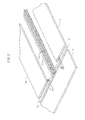
- FIG. 2 is a perspective view of a portion of the directional coupler of FIG. 1 in accordance with one embodiment of the invention.
- FIG. 3 is a expanded view of an end portion of the directional coupler of FIG. 2 in accordance with one embodiment of the invention.
- FIG. 4 is a cross sectional view of a cross section taken along the transmission line coupling segments of the directional coupler of FIG. 3 in accordance with one embodiment of the invention.
- first and second transmission line coupling segments (10a, 12a) each have an elongated body with a square or rectangular cross section and are positioned in a top plane.
- First and second transverse conductive segments (22, 24) each are attached to a bottom surface of one of the first and second transmission line segments (10a, 12a).
- the transverse conductive segments (22, 24) each have an elongated body and a rectangular cross section with a length of the cross section extending perpendicular to the bottom surfaces of each of the first and second transmission line segments (10a, 12a).
- Top surfaces of each of the third and fourth coupling segments (26, 28) are attached to the transverse conductive segments (22, 24), respectively.
- the third and fourth coupling segments (26, 28) each have a rectangular cross section with a length of the cross section extending perpendicular to the length of the cross section of the transverse conductive segments (22, 24).
- the third and fourth coupling segments (26, 28) are positioned below the first and second coupling segments (10a, 12a) in a bottom plane spaced apart from the top plane by a distance about equal to the length of one of the transverse conductive segments (22, 24).
- the first and second coupling segments (10a, 12a) are separated by a top coupling distance or gap 30, while the third and fourth coupling segments (26, 28) are separated by a bottom coupling distance or gap 32.
- the first coupling segment 10a, the first transverse conductive segment 22, and third coupling segment 26 form an I-beam cross section, or considered from a different direction, an H-beam cross section.
- the second coupling segment 12a, the second transverse conductive segment 24, and fourth coupling segment 28 form an I-beam cross section.
- the coupling segments (10a, 12a, 26, 28) can be referred to as flanges while the transverse conductive segments (22, 24) can be referred to as webs.
- the I-beam cross section with two flanges can provide for better coupling performance than conventional directional couplers.
- the third and fourth coupling segments (26, 28) can provide coupling in a second plane in addition to the primary coupling segments (e.g., 10a, 12a).
- the overall degree of coupling is a function of the distances or gaps (30, 32) between the coupling segments (10a, 12a, 26, 28) or flanges. More specifically, the smaller the gap (30, 32) between the flanges, the greater the coupling. The smaller gap can increase the capacitance between the transmission line (10a to 12a, 22 to 24, and 26 to 28) surfaces facing each other. In the embodiments illustrated in FIGs. 2-4 , the top gap 30 is about equal to the bottom gap 32. In other embodiments, the gaps can be unequal. In several embodiments, the distances or gap spacing are determined to achieve a degree of coupling that is about 3 dB, representing an equal split of the input power level. In other embodiments, other degrees of coupling can be achieved.
- the top gap is 2.9 microns
- the bottom gap is 2.9 microns.
- the first and second conductor widths (10a and 12a) can both be 3.7 microns
- the widths of the third and fourth transmission line conductors (26 and 28) can also be 3.7 microns.
- the widths of the transverse conductive segments (22 and 24) can both be 1.3 microns, the gap between them can be 5.3 microns.
- the gaps (30, 32) between the flanges are filled with air.
- other dielectric materials can fill the gaps.
- the gaps include various coatings including 1 um of oxygen, 1.35 um of silicon nitride, 0.45 um of nitride and an average of 2.5 um of polyimide.
- the higher the dielectric constant of the dielectric material used to fill the gaps the greater the gap spacing can be to achieve a preselected degree of coupling.
- each web is slightly offset from a center of the flanges it is attached to. More specifically, each web is slightly offset towards the opposing web. In some embodiments, each web can be positioned even closer to the opposing web then depicted in FIG. 4 . In other embodiments, each web can be centered with respect to the flanges attached thereto.
- the webs (22, 24) include periodic gaps 34 along the lengths of the webs. In other embodiments, these gaps can be wider than illustrated in FIGs. 2-3 . In some embodiments, no gap is present in the webs. In one embodiment, the gap is due to a design rule associated with a particular software layout tool. In some embodiments, the gaps has little or no effect on the coupling performance of the directional coupler. In such case, use of the gaps serve to minimize cost associated with unnecessary material.
- the directional coupler includes two coupling structures having an I-beam shaped cross section.
- the coupling structures can have other suitable cross sectional shapes.
- the coupling structures can have a J-shaped, T-shaped and/or L-shaped cross section.
- the shape of the coupling structure is determined, at least in part, based on design rules associated with a particular software layout tool for transmission lines. In one such embodiment, those design rules may be provided by a particular foundry supplying the layout tool.
- the directional coupler includes two symmetrical coupling structures. In other embodiments, the coupling structures are not symmetrical.
- the coupling structures are made of conductive materials.
- the flanges are made of copper and the webs are made of tungsten. In other embodiments, other suitable conductive materials can be used.
- the coupling structures are made of aluminum.
- the directional coupler can be considered a four port device having an input port P1, a transmitted port P2, a coupled port P3, and an isolated port P4.
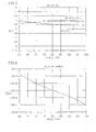
- FIG. 5 is a graph of coupling verses the frequency for a directional coupler in accordance with one embodiment of the invention.
- the trace (P3, P1) represents the logarithm of the ratio of the power into port P3 divided by the power out of the port P1 expressed in decibels.
- the trace (P2, P1) represents the degree of coupling appearing at the transmitted or direct port P2. As illustrated in FIG. 5 , the degree of coupling for the coupled port P3 is at least 3 dB and increases beyond 4 dB as the frequency increases for the given frequency range.
- FIG. 6 is a graph of relative phase verses the frequency for a directional coupler in accordance with one embodiment of the invention.
- the relative phase can be thought of as the difference in phase between an input wave to the directional coupler and an output wave of the directional coupler.
- FIG. 7 is a graph of return loss verses the frequency for each port of a directional coupler in accordance with one embodiment of the invention.
Landscapes
- Aerials With Secondary Devices (AREA)
- Near-Field Transmission Systems (AREA)
- Control Of Motors That Do Not Use Commutators (AREA)
Abstract
Description
- The present invention relates generally to directional couplers. More specifically, the invention relates to a microwave directional coupler having a structure that allows for coupling along more than one plane.
- Directional couplers are passive devices typically used in radio frequency applications to couple part of the transmission power or energy in a transmission line by a known amount out through another port. Often the coupling is achieved by using two transmission lines set close enough together such that energy passing through one line is coupled to the other line. Designers of directional couplers often need to determine a mechanical layout of these transmission lines to accomplish a preselected degree of coupling. Often this preselected degree of coupling is 3 dB or less and constrains the designer to position the lines very close together, which can create manufacturing and/or fabrication yield problems. More specifically, in some cases, the designer can be constrained by the rules associated with a design tool for laying out the transmission lines.
- Conventional directional couplers can include interdigitated coupling segments positioned on a flat surface.
U.S. Patent 3,516,024 to Lange describes such an interdigitated strip line coupler. A variation of the Lange coupler is described by Waugh and LaCombe in an IEEE article. (Waugh, R., LaCombe, D.: "'Unfolding' the Lange Coupler",. IEEE Trans., 1972, MTT-20, pp. 777-779). These conventional couplers can however be difficult and expensive to manufacture in some circumstances. In addition, the performance of these conventional couplers can be limited. - Aspects of the invention relate to directional couplers that allow for coupling on more than one plane. In one embodiment, the directional coupler includes first and second transmission line segments positioned on a first plane and spaced apart by a first distance, third and fourth transmission line segments positioned on a second plane and spaced apart by a second distance, the second plane spaced apart from the first plane, a first conductive segment connecting the first and third transmission line segments, and a second conductive segment connecting the second and fourth transmission line segments, where the first and second transmission line segments are configured to couple energy therebetween, and where the third and fourth transmission line segments are configured to couple energy therebetween.
-
-
FIG. 1 is a top view of a directional coupler in accordance with one embodiment of the invention. -
FIG. 2 is a perspective view of a portion of the directional coupler ofFIG. 1 in accordance with one embodiment of the invention. -
FIG. 3 is a expanded view of an end portion of the directional coupler ofFIG. 2 in accordance with one embodiment of the invention. -
FIG. 4 is a cross sectional view of a cross section taken along the transmission line coupling segments of the directional coupler ofFIG. 3 in accordance with one embodiment of the invention. -
FIG. 5 is a graph of coupling verses the frequency for a directional coupler in accordance with one embodiment of the invention. -
FIG. 6 is a graph of relative phase verses the frequency for a directional coupler in accordance with one embodiment of the invention. -
FIG. 7 is a graph of return loss verses the frequency for a directional coupler in accordance with one embodiment of the invention. - Referring now to the drawings, embodiments of directional couplers have a three dimensional structure that provides coupling on more than one plane. Embodiments of the coupler structures include first and second transmission line coupling segments positioned on a first plane, spaced apart by a first distance, and third and fourth transmission line coupling segments positioned on a second plane, spaced apart by a second distance, where the second plane is spaced apart from the first plane. Embodiments of the coupler structures further include conductive segments that connect the first and third transmission line segments, and the second and fourth transmission line segments, respectively. The first and second transmission line segments are configured to couple energy between the transmission line segments. Similarly, the third and fourth transmission line segments are configured to couple energy between the transmission line segments. In contrast to conventional directional couplers, embodiments of coupler structures described herein provide coupling on more than one plane using at least two transmission line coupling segments.
- In some embodiments, a cross section of the coupler structures can have a I-beam shape. In other embodiments, the coupler structures can have other suitable shapes.
-
FIG. 1 is a top view of a directional coupler in accordance with one embodiment of the invention. The directional coupler includes afirst transmission line 10 and asecond transmission line 12 interleaved among a number of interconnected ground planes (14, 16, 18, 20). The first and second transmission lines (10, 12) include closely positioned coupling segments (10a, 12a) disposed along a first plane that extends in the same plane as the ground planes (14, 16, 18, 20). The first and second transmission lines (10, 12) also include closely positioned coupling segments (seeFIG. 2 ) along a second plane positioned below, or spaced apart from, the first plane. -
FIG. 2 is a perspective view of a portion of the directional coupler ofFIG. 1 in accordance with one embodiment of the invention. -
FIG. 3 is a expanded view of an end portion of the directional coupler ofFIG. 2 in accordance with one embodiment of the invention. -
FIG. 4 is a cross sectional view of a cross section taken along the transmission line coupling segments of the directional coupler ofFIG. 3 in accordance with one embodiment of the invention. - Referring now to
FIGs. 2-4 , the first and second transmission line coupling segments (10a, 12a) each have an elongated body with a square or rectangular cross section and are positioned in a top plane. First and second transverse conductive segments (22, 24) each are attached to a bottom surface of one of the first and second transmission line segments (10a, 12a). The transverse conductive segments (22, 24) each have an elongated body and a rectangular cross section with a length of the cross section extending perpendicular to the bottom surfaces of each of the first and second transmission line segments (10a, 12a). Top surfaces of each of the third and fourth coupling segments (26, 28) are attached to the transverse conductive segments (22, 24), respectively. The third and fourth coupling segments (26, 28) each have a rectangular cross section with a length of the cross section extending perpendicular to the length of the cross section of the transverse conductive segments (22, 24). The third and fourth coupling segments (26, 28) are positioned below the first and second coupling segments (10a, 12a) in a bottom plane spaced apart from the top plane by a distance about equal to the length of one of the transverse conductive segments (22, 24). The first and second coupling segments (10a, 12a) are separated by a top coupling distance orgap 30, while the third and fourth coupling segments (26, 28) are separated by a bottom coupling distance orgap 32. - In the embodiments illustrated in
FIGs. 2-4 , thefirst coupling segment 10a, the first transverseconductive segment 22, andthird coupling segment 26 form an I-beam cross section, or considered from a different direction, an H-beam cross section. Similarly, thesecond coupling segment 12a, the second transverseconductive segment 24, andfourth coupling segment 28 form an I-beam cross section. For an I-beam cross section or other similar structure, the coupling segments (10a, 12a, 26, 28) can be referred to as flanges while the transverse conductive segments (22, 24) can be referred to as webs. The I-beam cross section with two flanges can provide for better coupling performance than conventional directional couplers. In particular, as compared to conventional couplers, the third and fourth coupling segments (26, 28) can provide coupling in a second plane in addition to the primary coupling segments (e.g., 10a, 12a). - The overall degree of coupling is a function of the distances or gaps (30, 32) between the coupling segments (10a, 12a, 26, 28) or flanges. More specifically, the smaller the gap (30, 32) between the flanges, the greater the coupling. The smaller gap can increase the capacitance between the transmission line (10a to 12a, 22 to 24, and 26 to 28) surfaces facing each other. In the embodiments illustrated in
FIGs. 2-4 , thetop gap 30 is about equal to thebottom gap 32. In other embodiments, the gaps can be unequal. In several embodiments, the distances or gap spacing are determined to achieve a degree of coupling that is about 3 dB, representing an equal split of the input power level. In other embodiments, other degrees of coupling can be achieved. In one embodiment, the top gap is 2.9 microns, and the bottom gap is 2.9 microns. In such case, the first and second conductor widths (10a and 12a) can both be 3.7 microns, while the widths of the third and fourth transmission line conductors (26 and 28) can also be 3.7 microns. The widths of the transverse conductive segments (22 and 24) can both be 1.3 microns, the gap between them can be 5.3 microns. - In several embodiments, the gaps (30, 32) between the flanges are filled with air. In other embodiments, other dielectric materials can fill the gaps. In such embodiment, the gaps include various coatings including 1 um of oxygen, 1.35 um of silicon nitride, 0.45 um of nitride and an average of 2.5 um of polyimide. In several embodiments, the higher the dielectric constant of the dielectric material used to fill the gaps, the greater the gap spacing can be to achieve a preselected degree of coupling.
- In the embodiments illustrated in
FIGs. 2-4 , there are two flanges (10a, 26 and 12a, 28) coupled by a single web (22 and 24) for each transmission line (10 and 12). In other embodiments, the transmission line coupling structures may include more than two flanges and additional webs for additional coupling. In one such case, an additional flange is positioned on a third plane spaced apart from the top and bottom planes and coupled to eitherflange FIG. 4 , each web is slightly offset from a center of the flanges it is attached to. More specifically, each web is slightly offset towards the opposing web. In some embodiments, each web can be positioned even closer to the opposing web then depicted inFIG. 4 . In other embodiments, each web can be centered with respect to the flanges attached thereto. - In the embodiment illustrated in
FIGs. 2-3 , the webs (22, 24) includeperiodic gaps 34 along the lengths of the webs. In other embodiments, these gaps can be wider than illustrated inFIGs. 2-3 . In some embodiments, no gap is present in the webs. In one embodiment, the gap is due to a design rule associated with a particular software layout tool. In some embodiments, the gaps has little or no effect on the coupling performance of the directional coupler. In such case, use of the gaps serve to minimize cost associated with unnecessary material. - In the embodiments illustrated in
FIGs. 2-4 , the directional coupler includes two coupling structures having an I-beam shaped cross section. In other embodiments, the coupling structures can have other suitable cross sectional shapes. In one such embodiment, for example, the coupling structures can have a J-shaped, T-shaped and/or L-shaped cross section. In some embodiments, the shape of the coupling structure is determined, at least in part, based on design rules associated with a particular software layout tool for transmission lines. In one such embodiment, those design rules may be provided by a particular foundry supplying the layout tool. In the embodiments illustrated inFIGs. 2-4 , the directional coupler includes two symmetrical coupling structures. In other embodiments, the coupling structures are not symmetrical. - In several embodiments, the coupling structures are made of conductive materials. In one embodiment, for example, the flanges are made of copper and the webs are made of tungsten. In other embodiments, other suitable conductive materials can be used. In some embodiments, the coupling structures are made of aluminum.
- Returning briefly to
FIG. 1 , for an electrical performance analysis, the directional coupler can be considered a four port device having an input port P1, a transmitted port P2, a coupled port P3, and an isolated port P4. -
FIG. 5 is a graph of coupling verses the frequency for a directional coupler in accordance with one embodiment of the invention. The trace (P3, P1) represents the logarithm of the ratio of the power into port P3 divided by the power out of the port P1 expressed in decibels. The trace (P2, P1) represents the degree of coupling appearing at the transmitted or direct port P2. As illustrated inFIG. 5 , the degree of coupling for the coupled port P3 is at least 3 dB and increases beyond 4 dB as the frequency increases for the given frequency range. -
FIG. 6 is a graph of relative phase verses the frequency for a directional coupler in accordance with one embodiment of the invention. The relative phase can be thought of as the difference in phase between an input wave to the directional coupler and an output wave of the directional coupler. -
FIG. 7 is a graph of return loss verses the frequency for each port of a directional coupler in accordance with one embodiment of the invention. - While the above description contains many specific embodiments of the invention, these should not be construed as limitations on the scope of the invention, but rather as examples of specific embodiments thereof. Accordingly, the scope of the invention should be determined not by the embodiments illustrated, but by the appended claims and their equivalents.
Claims (10)
- A directional coupler comprising:first and second transmission line segments positioned on a first plane and spaced apart by a first distance;third and fourth transmission line segments positioned on a second plane and spaced apart by a second distance, the second plane spaced apart from the first plane;a first conductive segment connecting the first and third transmission line segments; anda second conductive segment connecting the second and fourth transmission line segments,wherein the first and second transmission line segments are configured to couple energy therebetween, andwherein the third and fourth transmission line segments are configured to couple energy therebetween.
- The coupler of claim 1:wherein an amount of energy coupled between the first and second transmission line segments is determined, at least in part, by the first distance; andwherein an amount of energy coupled between the third and fourth transmission line segments is determined, at least in part, by the second distance.
- The coupler of claim 1:wherein the first transmission line segment, the third transmission line segment, and the first conductive segment comprise an I-beam shaped cross section; andwherein the second transmission line segment, the fourth transmission line segment, and the second conductive segment comprise an I-beam shaped cross section.
- The coupler of claim 1:wherein the first transmission line segment, the third transmission line segment, and the first conductive segment comprise an J-shaped cross section; andwherein the second transmission line segment, the fourth transmission line segment, and the second conductive segment comprise an J-shaped cross section.
- The coupler of claim 1:wherein the first and second transmission line segments comprise a conductor having a rectangular cross section and an elongated length;wherein the third and fourth transmission line segments comprise a conductor having a rectangular cross section and an elongated length; andwherein the first and second conductive segments comprise a conductor having a rectangular cross section and an elongated length.
- The coupler of claim 5:wherein a length of each of the rectangular cross sections of the first, second, third, and fourth transmission line segments extends in a first direction;wherein a length of each of the rectangular cross sections of the first and second conductive segments extends in a second direction transverse to the first direction.
- The coupler of claim 5:wherein the elongated lengths of the first and second conductive segments comprise periodic gaps.
- The coupler of claim 1, further comprising:fifth and sixth transmission line segments positioned on a third plane and spaced apart by a third distance, the third plane spaced apart from the first and second planes; anda third conductive segment connecting the fifth and sixth transmission line segments; andwherein the fifth and sixth transmission line segments are configured to couple energy therebetween.
- The coupler of claim 1, wherein the first, second, third, and fourth transmission line segments comprise at least one conductive material.
- The coupler of claim 9:wherein the at least conductive material comprises copper, andwherein the first and second conductive segments comprise tungsten.
Applications Claiming Priority (1)
| Application Number | Priority Date | Filing Date | Title |
|---|---|---|---|
| US12/790,507 US8446230B2 (en) | 2010-05-28 | 2010-05-28 | Microwave directional coupler |
Publications (2)
| Publication Number | Publication Date |
|---|---|
| EP2390954A1 true EP2390954A1 (en) | 2011-11-30 |
| EP2390954B1 EP2390954B1 (en) | 2013-05-01 |
Family
ID=44064608
Family Applications (1)
| Application Number | Title | Priority Date | Filing Date |
|---|---|---|---|
| EP11154825.1A Active EP2390954B1 (en) | 2010-05-28 | 2011-02-17 | Microwave directional coupler |
Country Status (3)
| Country | Link |
|---|---|
| US (1) | US8446230B2 (en) |
| EP (1) | EP2390954B1 (en) |
| IL (1) | IL211106A0 (en) |
Families Citing this family (3)
| Publication number | Priority date | Publication date | Assignee | Title |
|---|---|---|---|---|
| EP3147995B1 (en) * | 2015-09-25 | 2018-04-11 | Rohde & Schwarz GmbH & Co. KG | Power directional coupler, combiner and method for manufacturing |
| CN108022905A (en) * | 2016-11-04 | 2018-05-11 | 超威半导体公司 | Use the switching board transmission line of multiple metal layers |
| US10673119B2 (en) * | 2017-10-20 | 2020-06-02 | Raytheon Company | Highly directive electromagnetic coupler with electrically large conductor |
Citations (4)
| Publication number | Priority date | Publication date | Assignee | Title |
|---|---|---|---|---|
| US3516024A (en) | 1968-12-30 | 1970-06-02 | Texas Instruments Inc | Interdigitated strip line coupler |
| JPS54132154A (en) * | 1978-04-06 | 1979-10-13 | Hitachi Cable Ltd | Directional coupler |
| JP2006074830A (en) * | 2005-11-07 | 2006-03-16 | Murata Mfg Co Ltd | Directional coupler |
| EP1753072A1 (en) * | 2004-05-18 | 2007-02-14 | Murata Manufacturing Co., Ltd. | Directional coupler |
Family Cites Families (6)
| Publication number | Priority date | Publication date | Assignee | Title |
|---|---|---|---|---|
| US4459568A (en) * | 1982-02-02 | 1984-07-10 | Rockwell International Corporation | Air-stripline overlay hybrid coupler |
| US5111165A (en) * | 1989-07-11 | 1992-05-05 | Wiltron Company | Microwave coupler and method of operating same utilizing forward coupling |
| US5012209A (en) * | 1990-01-12 | 1991-04-30 | Raytheon Company | Broadband stripline coupler |
| US6166441A (en) * | 1998-11-12 | 2000-12-26 | Intel Corporation | Method of forming a via overlap |
| SE518100C2 (en) * | 2000-12-04 | 2002-08-27 | Ericsson Telefon Ab L M | Directional switch, antenna interface unit and radio base station including antenna interface unit |
| KR100622178B1 (en) * | 2002-07-05 | 2006-09-14 | 마츠시타 덴끼 산교 가부시키가이샤 | Combiner |
-
2010
- 2010-05-28 US US12/790,507 patent/US8446230B2/en active Active
-
2011
- 2011-02-07 IL IL211106A patent/IL211106A0/en active IP Right Grant
- 2011-02-17 EP EP11154825.1A patent/EP2390954B1/en active Active
Patent Citations (4)
| Publication number | Priority date | Publication date | Assignee | Title |
|---|---|---|---|---|
| US3516024A (en) | 1968-12-30 | 1970-06-02 | Texas Instruments Inc | Interdigitated strip line coupler |
| JPS54132154A (en) * | 1978-04-06 | 1979-10-13 | Hitachi Cable Ltd | Directional coupler |
| EP1753072A1 (en) * | 2004-05-18 | 2007-02-14 | Murata Manufacturing Co., Ltd. | Directional coupler |
| JP2006074830A (en) * | 2005-11-07 | 2006-03-16 | Murata Mfg Co Ltd | Directional coupler |
Non-Patent Citations (1)
| Title |
|---|
| WAUGH, R.; LACOMBE, D: "Unfolding' the Lange Coupler", IEEE TRANS., vol. MTT-20, 1972, pages 777 - 779 |
Also Published As
| Publication number | Publication date |
|---|---|
| US8446230B2 (en) | 2013-05-21 |
| US20110291770A1 (en) | 2011-12-01 |
| IL211106A0 (en) | 2011-06-30 |
| EP2390954B1 (en) | 2013-05-01 |
Similar Documents
| Publication | Publication Date | Title |
|---|---|---|
| US9136579B2 (en) | Phase shifter using substrate integrated waveguide | |
| US8299871B2 (en) | Directional coupler | |
| US9343795B1 (en) | Wideband unbalanced waveguide power dividers and combiners | |
| US7994879B2 (en) | Apparatus for transitioning millimeter wave between dielectric waveguide and transmission line | |
| US20040263281A1 (en) | Coupler having an uncoupled section | |
| CN112272900B (en) | Helical UWB Microstrip Orthogonal Directional Coupler | |
| US8884716B2 (en) | Feeding structure for cavity resonators | |
| TWI631764B (en) | Coupler with reduced coupling coefficient variation, method of manufacturing the same, and related package wafer and wireless device | |
| US20200136584A1 (en) | Diplexer and multiplexer | |
| JP6093743B2 (en) | Millimeter wave transmission line conversion structure | |
| KR100967153B1 (en) | Waveguide magic t | |
| Wu et al. | Guided-wave properties of synthesized nonradiative dielectric waveguide for substrate integrated circuits (SICs) | |
| EP2390954B1 (en) | Microwave directional coupler | |
| CN107611539A (en) | A kind of frequency and the individually controllable millimeter wave double-passband filter of bandwidth | |
| CN106876858B (en) | A kind of braodband directional coupler | |
| CN112803134A (en) | Quartering microstrip power divider | |
| US9478840B2 (en) | Transmission line and methods for fabricating thereof | |
| CN101783431A (en) | Complementary metal coupling line | |
| CN103078164B (en) | Compact single-row long-hole directional coupler | |
| Nasr et al. | Design of an UWB power splitter of arbitrary split ratio using asymmetrical double ridge waveguide | |
| Sinulingga et al. | Perturbation effect on a dual mode CPW multilayer MMIC bandpass filter | |
| JP2011147081A (en) | Waveguide connection method | |
| CN116487842B (en) | A phase shifter based on defective ground structure | |
| US20180034127A1 (en) | Planar type magic tee | |
| KR102302423B1 (en) | Microstrip Directional Coupler |
Legal Events
| Date | Code | Title | Description |
|---|---|---|---|
| 17P | Request for examination filed |
Effective date: 20110314 |
|
| AK | Designated contracting states |
Kind code of ref document: A1 Designated state(s): AL AT BE BG CH CY CZ DE DK EE ES FI FR GB GR HR HU IE IS IT LI LT LU LV MC MK MT NL NO PL PT RO RS SE SI SK SM TR |
|
| AX | Request for extension of the european patent |
Extension state: BA ME |
|
| PUAI | Public reference made under article 153(3) epc to a published international application that has entered the european phase |
Free format text: ORIGINAL CODE: 0009012 |
|
| 17Q | First examination report despatched |
Effective date: 20120816 |
|
| GRAP | Despatch of communication of intention to grant a patent |
Free format text: ORIGINAL CODE: EPIDOSNIGR1 |
|
| GRAS | Grant fee paid |
Free format text: ORIGINAL CODE: EPIDOSNIGR3 |
|
| GRAA | (expected) grant |
Free format text: ORIGINAL CODE: 0009210 |
|
| AK | Designated contracting states |
Kind code of ref document: B1 Designated state(s): AL AT BE BG CH CY CZ DE DK EE ES FI FR GB GR HR HU IE IS IT LI LT LU LV MC MK MT NL NO PL PT RO RS SE SI SK SM TR |
|
| REG | Reference to a national code |
Ref country code: GB Ref legal event code: FG4D |
|
| REG | Reference to a national code |
Ref country code: CH Ref legal event code: EP Ref country code: AT Ref legal event code: REF Ref document number: 610428 Country of ref document: AT Kind code of ref document: T Effective date: 20130515 |
|
| REG | Reference to a national code |
Ref country code: IE Ref legal event code: FG4D |
|
| REG | Reference to a national code |
Ref country code: DE Ref legal event code: R096 Ref document number: 602011001487 Country of ref document: DE Effective date: 20130704 |
|
| REG | Reference to a national code |
Ref country code: AT Ref legal event code: MK05 Ref document number: 610428 Country of ref document: AT Kind code of ref document: T Effective date: 20130501 |
|
| REG | Reference to a national code |
Ref country code: NL Ref legal event code: VDEP Effective date: 20130501 |
|
| REG | Reference to a national code |
Ref country code: LT Ref legal event code: MG4D |
|
| PG25 | Lapsed in a contracting state [announced via postgrant information from national office to epo] |
Ref country code: PT Free format text: LAPSE BECAUSE OF FAILURE TO SUBMIT A TRANSLATION OF THE DESCRIPTION OR TO PAY THE FEE WITHIN THE PRESCRIBED TIME-LIMIT Effective date: 20130902 Ref country code: SE Free format text: LAPSE BECAUSE OF FAILURE TO SUBMIT A TRANSLATION OF THE DESCRIPTION OR TO PAY THE FEE WITHIN THE PRESCRIBED TIME-LIMIT Effective date: 20130501 Ref country code: IS Free format text: LAPSE BECAUSE OF FAILURE TO SUBMIT A TRANSLATION OF THE DESCRIPTION OR TO PAY THE FEE WITHIN THE PRESCRIBED TIME-LIMIT Effective date: 20130901 Ref country code: AT Free format text: LAPSE BECAUSE OF FAILURE TO SUBMIT A TRANSLATION OF THE DESCRIPTION OR TO PAY THE FEE WITHIN THE PRESCRIBED TIME-LIMIT Effective date: 20130501 Ref country code: LT Free format text: LAPSE BECAUSE OF FAILURE TO SUBMIT A TRANSLATION OF THE DESCRIPTION OR TO PAY THE FEE WITHIN THE PRESCRIBED TIME-LIMIT Effective date: 20130501 Ref country code: NO Free format text: LAPSE BECAUSE OF FAILURE TO SUBMIT A TRANSLATION OF THE DESCRIPTION OR TO PAY THE FEE WITHIN THE PRESCRIBED TIME-LIMIT Effective date: 20130801 Ref country code: FI Free format text: LAPSE BECAUSE OF FAILURE TO SUBMIT A TRANSLATION OF THE DESCRIPTION OR TO PAY THE FEE WITHIN THE PRESCRIBED TIME-LIMIT Effective date: 20130501 Ref country code: ES Free format text: LAPSE BECAUSE OF FAILURE TO SUBMIT A TRANSLATION OF THE DESCRIPTION OR TO PAY THE FEE WITHIN THE PRESCRIBED TIME-LIMIT Effective date: 20130812 Ref country code: SI Free format text: LAPSE BECAUSE OF FAILURE TO SUBMIT A TRANSLATION OF THE DESCRIPTION OR TO PAY THE FEE WITHIN THE PRESCRIBED TIME-LIMIT Effective date: 20130501 Ref country code: GR Free format text: LAPSE BECAUSE OF FAILURE TO SUBMIT A TRANSLATION OF THE DESCRIPTION OR TO PAY THE FEE WITHIN THE PRESCRIBED TIME-LIMIT Effective date: 20130802 |
|
| PG25 | Lapsed in a contracting state [announced via postgrant information from national office to epo] |
Ref country code: BG Free format text: LAPSE BECAUSE OF FAILURE TO SUBMIT A TRANSLATION OF THE DESCRIPTION OR TO PAY THE FEE WITHIN THE PRESCRIBED TIME-LIMIT Effective date: 20130801 Ref country code: HR Free format text: LAPSE BECAUSE OF FAILURE TO SUBMIT A TRANSLATION OF THE DESCRIPTION OR TO PAY THE FEE WITHIN THE PRESCRIBED TIME-LIMIT Effective date: 20130501 Ref country code: RS Free format text: LAPSE BECAUSE OF FAILURE TO SUBMIT A TRANSLATION OF THE DESCRIPTION OR TO PAY THE FEE WITHIN THE PRESCRIBED TIME-LIMIT Effective date: 20130501 Ref country code: PL Free format text: LAPSE BECAUSE OF FAILURE TO SUBMIT A TRANSLATION OF THE DESCRIPTION OR TO PAY THE FEE WITHIN THE PRESCRIBED TIME-LIMIT Effective date: 20130501 Ref country code: CY Free format text: LAPSE BECAUSE OF FAILURE TO SUBMIT A TRANSLATION OF THE DESCRIPTION OR TO PAY THE FEE WITHIN THE PRESCRIBED TIME-LIMIT Effective date: 20130501 |
|
| PG25 | Lapsed in a contracting state [announced via postgrant information from national office to epo] |
Ref country code: LV Free format text: LAPSE BECAUSE OF FAILURE TO SUBMIT A TRANSLATION OF THE DESCRIPTION OR TO PAY THE FEE WITHIN THE PRESCRIBED TIME-LIMIT Effective date: 20130501 |
|
| PG25 | Lapsed in a contracting state [announced via postgrant information from national office to epo] |
Ref country code: DK Free format text: LAPSE BECAUSE OF FAILURE TO SUBMIT A TRANSLATION OF THE DESCRIPTION OR TO PAY THE FEE WITHIN THE PRESCRIBED TIME-LIMIT Effective date: 20130501 Ref country code: EE Free format text: LAPSE BECAUSE OF FAILURE TO SUBMIT A TRANSLATION OF THE DESCRIPTION OR TO PAY THE FEE WITHIN THE PRESCRIBED TIME-LIMIT Effective date: 20130501 Ref country code: CZ Free format text: LAPSE BECAUSE OF FAILURE TO SUBMIT A TRANSLATION OF THE DESCRIPTION OR TO PAY THE FEE WITHIN THE PRESCRIBED TIME-LIMIT Effective date: 20130501 Ref country code: BE Free format text: LAPSE BECAUSE OF FAILURE TO SUBMIT A TRANSLATION OF THE DESCRIPTION OR TO PAY THE FEE WITHIN THE PRESCRIBED TIME-LIMIT Effective date: 20130501 Ref country code: SK Free format text: LAPSE BECAUSE OF FAILURE TO SUBMIT A TRANSLATION OF THE DESCRIPTION OR TO PAY THE FEE WITHIN THE PRESCRIBED TIME-LIMIT Effective date: 20130501 |
|
| PG25 | Lapsed in a contracting state [announced via postgrant information from national office to epo] |
Ref country code: NL Free format text: LAPSE BECAUSE OF FAILURE TO SUBMIT A TRANSLATION OF THE DESCRIPTION OR TO PAY THE FEE WITHIN THE PRESCRIBED TIME-LIMIT Effective date: 20130501 Ref country code: RO Free format text: LAPSE BECAUSE OF FAILURE TO SUBMIT A TRANSLATION OF THE DESCRIPTION OR TO PAY THE FEE WITHIN THE PRESCRIBED TIME-LIMIT Effective date: 20130501 Ref country code: IT Free format text: LAPSE BECAUSE OF FAILURE TO SUBMIT A TRANSLATION OF THE DESCRIPTION OR TO PAY THE FEE WITHIN THE PRESCRIBED TIME-LIMIT Effective date: 20130501 |
|
| PLBE | No opposition filed within time limit |
Free format text: ORIGINAL CODE: 0009261 |
|
| STAA | Information on the status of an ep patent application or granted ep patent |
Free format text: STATUS: NO OPPOSITION FILED WITHIN TIME LIMIT |
|
| 26N | No opposition filed |
Effective date: 20140204 |
|
| REG | Reference to a national code |
Ref country code: DE Ref legal event code: R097 Ref document number: 602011001487 Country of ref document: DE Effective date: 20140204 |
|
| PG25 | Lapsed in a contracting state [announced via postgrant information from national office to epo] |
Ref country code: MC Free format text: LAPSE BECAUSE OF FAILURE TO SUBMIT A TRANSLATION OF THE DESCRIPTION OR TO PAY THE FEE WITHIN THE PRESCRIBED TIME-LIMIT Effective date: 20130501 Ref country code: LU Free format text: LAPSE BECAUSE OF FAILURE TO SUBMIT A TRANSLATION OF THE DESCRIPTION OR TO PAY THE FEE WITHIN THE PRESCRIBED TIME-LIMIT Effective date: 20140217 |
|
| REG | Reference to a national code |
Ref country code: CH Ref legal event code: PL |
|
| PG25 | Lapsed in a contracting state [announced via postgrant information from national office to epo] |
Ref country code: LI Free format text: LAPSE BECAUSE OF NON-PAYMENT OF DUE FEES Effective date: 20140228 Ref country code: CH Free format text: LAPSE BECAUSE OF NON-PAYMENT OF DUE FEES Effective date: 20140228 |
|
| REG | Reference to a national code |
Ref country code: IE Ref legal event code: MM4A |
|
| PG25 | Lapsed in a contracting state [announced via postgrant information from national office to epo] |
Ref country code: IE Free format text: LAPSE BECAUSE OF NON-PAYMENT OF DUE FEES Effective date: 20140217 |
|
| REG | Reference to a national code |
Ref country code: FR Ref legal event code: PLFP Year of fee payment: 5 |
|
| REG | Reference to a national code |
Ref country code: FR Ref legal event code: PLFP Year of fee payment: 6 |
|
| PG25 | Lapsed in a contracting state [announced via postgrant information from national office to epo] |
Ref country code: MT Free format text: LAPSE BECAUSE OF FAILURE TO SUBMIT A TRANSLATION OF THE DESCRIPTION OR TO PAY THE FEE WITHIN THE PRESCRIBED TIME-LIMIT Effective date: 20130501 |
|
| PG25 | Lapsed in a contracting state [announced via postgrant information from national office to epo] |
Ref country code: SM Free format text: LAPSE BECAUSE OF FAILURE TO SUBMIT A TRANSLATION OF THE DESCRIPTION OR TO PAY THE FEE WITHIN THE PRESCRIBED TIME-LIMIT Effective date: 20130501 |
|
| PG25 | Lapsed in a contracting state [announced via postgrant information from national office to epo] |
Ref country code: HU Free format text: LAPSE BECAUSE OF FAILURE TO SUBMIT A TRANSLATION OF THE DESCRIPTION OR TO PAY THE FEE WITHIN THE PRESCRIBED TIME-LIMIT; INVALID AB INITIO Effective date: 20110217 Ref country code: TR Free format text: LAPSE BECAUSE OF FAILURE TO SUBMIT A TRANSLATION OF THE DESCRIPTION OR TO PAY THE FEE WITHIN THE PRESCRIBED TIME-LIMIT Effective date: 20130501 |
|
| REG | Reference to a national code |
Ref country code: FR Ref legal event code: PLFP Year of fee payment: 7 |
|
| REG | Reference to a national code |
Ref country code: FR Ref legal event code: PLFP Year of fee payment: 8 |
|
| PG25 | Lapsed in a contracting state [announced via postgrant information from national office to epo] |
Ref country code: MK Free format text: LAPSE BECAUSE OF FAILURE TO SUBMIT A TRANSLATION OF THE DESCRIPTION OR TO PAY THE FEE WITHIN THE PRESCRIBED TIME-LIMIT Effective date: 20130501 |
|
| PG25 | Lapsed in a contracting state [announced via postgrant information from national office to epo] |
Ref country code: AL Free format text: LAPSE BECAUSE OF FAILURE TO SUBMIT A TRANSLATION OF THE DESCRIPTION OR TO PAY THE FEE WITHIN THE PRESCRIBED TIME-LIMIT Effective date: 20130501 |
|
| P01 | Opt-out of the competence of the unified patent court (upc) registered |
Effective date: 20230530 |
|
| PGFP | Annual fee paid to national office [announced via postgrant information from national office to epo] |
Ref country code: GB Payment date: 20260121 Year of fee payment: 16 |
|
| PGFP | Annual fee paid to national office [announced via postgrant information from national office to epo] |
Ref country code: DE Payment date: 20260121 Year of fee payment: 16 |
|
| PGFP | Annual fee paid to national office [announced via postgrant information from national office to epo] |
Ref country code: FR Payment date: 20260121 Year of fee payment: 16 |