EP2390940A1 - Battery pack - Google Patents
Battery pack Download PDFInfo
- Publication number
- EP2390940A1 EP2390940A1 EP10174093A EP10174093A EP2390940A1 EP 2390940 A1 EP2390940 A1 EP 2390940A1 EP 10174093 A EP10174093 A EP 10174093A EP 10174093 A EP10174093 A EP 10174093A EP 2390940 A1 EP2390940 A1 EP 2390940A1
- Authority
- EP
- European Patent Office
- Prior art keywords
- coupling portion
- housing
- battery pack
- cover
- battery cell
- Prior art date
- Legal status (The legal status is an assumption and is not a legal conclusion. Google has not performed a legal analysis and makes no representation as to the accuracy of the status listed.)
- Granted
Links
- 230000008878 coupling Effects 0.000 claims abstract description 144
- 238000010168 coupling process Methods 0.000 claims abstract description 144
- 238000005859 coupling reaction Methods 0.000 claims abstract description 144
- 230000003247 decreasing effect Effects 0.000 claims description 4
- 230000004048 modification Effects 0.000 description 7
- 238000012986 modification Methods 0.000 description 7
- -1 PolyChloroTriFluoroethylene Polymers 0.000 description 5
- 238000001746 injection moulding Methods 0.000 description 4
- 239000000463 material Substances 0.000 description 4
- 230000009977 dual effect Effects 0.000 description 3
- SLGWESQGEUXWJQ-UHFFFAOYSA-N formaldehyde;phenol Chemical compound O=C.OC1=CC=CC=C1 SLGWESQGEUXWJQ-UHFFFAOYSA-N 0.000 description 3
- 229920001568 phenolic resin Polymers 0.000 description 3
- 229920006324 polyoxymethylene Polymers 0.000 description 3
- HBBGRARXTFLTSG-UHFFFAOYSA-N Lithium ion Chemical compound [Li+] HBBGRARXTFLTSG-UHFFFAOYSA-N 0.000 description 2
- 229930040373 Paraformaldehyde Natural products 0.000 description 2
- 239000004952 Polyamide Substances 0.000 description 2
- 229920002367 Polyisobutene Polymers 0.000 description 2
- 239000004743 Polypropylene Substances 0.000 description 2
- 239000004372 Polyvinyl alcohol Substances 0.000 description 2
- 229920001756 Polyvinyl chloride acetate Polymers 0.000 description 2
- 238000000605 extraction Methods 0.000 description 2
- 229910001416 lithium ion Inorganic materials 0.000 description 2
- 238000012544 monitoring process Methods 0.000 description 2
- 229920003023 plastic Polymers 0.000 description 2
- 239000004033 plastic Substances 0.000 description 2
- 239000000088 plastic resin Substances 0.000 description 2
- 229920002493 poly(chlorotrifluoroethylene) Polymers 0.000 description 2
- 229920003229 poly(methyl methacrylate) Polymers 0.000 description 2
- 229920002037 poly(vinyl butyral) polymer Polymers 0.000 description 2
- 229920002647 polyamide Polymers 0.000 description 2
- 239000005023 polychlorotrifluoroethylene (PCTFE) polymer Substances 0.000 description 2
- 229920000139 polyethylene terephthalate Polymers 0.000 description 2
- 239000005020 polyethylene terephthalate Substances 0.000 description 2
- 229920000642 polymer Polymers 0.000 description 2
- 239000004926 polymethyl methacrylate Substances 0.000 description 2
- 229920001155 polypropylene Polymers 0.000 description 2
- 229920001343 polytetrafluoroethylene Polymers 0.000 description 2
- 239000004810 polytetrafluoroethylene Substances 0.000 description 2
- 229920002635 polyurethane Polymers 0.000 description 2
- 239000004814 polyurethane Substances 0.000 description 2
- 239000011118 polyvinyl acetate Substances 0.000 description 2
- 229920002689 polyvinyl acetate Polymers 0.000 description 2
- 229940075065 polyvinyl acetate Drugs 0.000 description 2
- 229920002451 polyvinyl alcohol Polymers 0.000 description 2
- 229940068984 polyvinyl alcohol Drugs 0.000 description 2
- 235000019422 polyvinyl alcohol Nutrition 0.000 description 2
- 229920002620 polyvinyl fluoride Polymers 0.000 description 2
- 230000002787 reinforcement Effects 0.000 description 2
- 239000004641 Diallyl-phthalate Substances 0.000 description 1
- WHXSMMKQMYFTQS-UHFFFAOYSA-N Lithium Chemical compound [Li] WHXSMMKQMYFTQS-UHFFFAOYSA-N 0.000 description 1
- 239000004698 Polyethylene Substances 0.000 description 1
- 239000004793 Polystyrene Substances 0.000 description 1
- QUDWYFHPNIMBFC-UHFFFAOYSA-N bis(prop-2-enyl) benzene-1,2-dicarboxylate Chemical compound C=CCOC(=O)C1=CC=CC=C1C(=O)OCC=C QUDWYFHPNIMBFC-UHFFFAOYSA-N 0.000 description 1
- 239000003792 electrolyte Substances 0.000 description 1
- 238000002347 injection Methods 0.000 description 1
- 239000007924 injection Substances 0.000 description 1
- 229910052744 lithium Inorganic materials 0.000 description 1
- 239000004417 polycarbonate Substances 0.000 description 1
- 229920000515 polycarbonate Polymers 0.000 description 1
- 229920000573 polyethylene Polymers 0.000 description 1
- 239000004800 polyvinyl chloride Substances 0.000 description 1
- 239000005033 polyvinylidene chloride Substances 0.000 description 1
- 230000003014 reinforcing effect Effects 0.000 description 1
- 229920002554 vinyl polymer Polymers 0.000 description 1
Images


Classifications
-
- H—ELECTRICITY
- H01—ELECTRIC ELEMENTS
- H01M—PROCESSES OR MEANS, e.g. BATTERIES, FOR THE DIRECT CONVERSION OF CHEMICAL ENERGY INTO ELECTRICAL ENERGY
- H01M50/00—Constructional details or processes of manufacture of the non-active parts of electrochemical cells other than fuel cells, e.g. hybrid cells
- H01M50/20—Mountings; Secondary casings or frames; Racks, modules or packs; Suspension devices; Shock absorbers; Transport or carrying devices; Holders
- H01M50/258—Modular batteries; Casings provided with means for assembling
- H01M50/26—Assemblies sealed to each other in a non-detachable manner
-
- H—ELECTRICITY
- H01—ELECTRIC ELEMENTS
- H01M—PROCESSES OR MEANS, e.g. BATTERIES, FOR THE DIRECT CONVERSION OF CHEMICAL ENERGY INTO ELECTRICAL ENERGY
- H01M50/00—Constructional details or processes of manufacture of the non-active parts of electrochemical cells other than fuel cells, e.g. hybrid cells
- H01M50/20—Mountings; Secondary casings or frames; Racks, modules or packs; Suspension devices; Shock absorbers; Transport or carrying devices; Holders
- H01M50/204—Racks, modules or packs for multiple batteries or multiple cells
- H01M50/207—Racks, modules or packs for multiple batteries or multiple cells characterised by their shape
- H01M50/209—Racks, modules or packs for multiple batteries or multiple cells characterised by their shape adapted for prismatic or rectangular cells
-
- H—ELECTRICITY
- H01—ELECTRIC ELEMENTS
- H01M—PROCESSES OR MEANS, e.g. BATTERIES, FOR THE DIRECT CONVERSION OF CHEMICAL ENERGY INTO ELECTRICAL ENERGY
- H01M50/00—Constructional details or processes of manufacture of the non-active parts of electrochemical cells other than fuel cells, e.g. hybrid cells
- H01M50/20—Mountings; Secondary casings or frames; Racks, modules or packs; Suspension devices; Shock absorbers; Transport or carrying devices; Holders
- H01M50/233—Mountings; Secondary casings or frames; Racks, modules or packs; Suspension devices; Shock absorbers; Transport or carrying devices; Holders characterised by physical properties of casings or racks, e.g. dimensions
- H01M50/242—Mountings; Secondary casings or frames; Racks, modules or packs; Suspension devices; Shock absorbers; Transport or carrying devices; Holders characterised by physical properties of casings or racks, e.g. dimensions adapted for protecting batteries against vibrations, collision impact or swelling
-
- H—ELECTRICITY
- H01—ELECTRIC ELEMENTS
- H01M—PROCESSES OR MEANS, e.g. BATTERIES, FOR THE DIRECT CONVERSION OF CHEMICAL ENERGY INTO ELECTRICAL ENERGY
- H01M50/00—Constructional details or processes of manufacture of the non-active parts of electrochemical cells other than fuel cells, e.g. hybrid cells
- H01M50/20—Mountings; Secondary casings or frames; Racks, modules or packs; Suspension devices; Shock absorbers; Transport or carrying devices; Holders
- H01M50/271—Lids or covers for the racks or secondary casings
-
- H—ELECTRICITY
- H01—ELECTRIC ELEMENTS
- H01M—PROCESSES OR MEANS, e.g. BATTERIES, FOR THE DIRECT CONVERSION OF CHEMICAL ENERGY INTO ELECTRICAL ENERGY
- H01M50/00—Constructional details or processes of manufacture of the non-active parts of electrochemical cells other than fuel cells, e.g. hybrid cells
- H01M50/50—Current conducting connections for cells or batteries
- H01M50/502—Interconnectors for connecting terminals of adjacent batteries; Interconnectors for connecting cells outside a battery casing
-
- Y—GENERAL TAGGING OF NEW TECHNOLOGICAL DEVELOPMENTS; GENERAL TAGGING OF CROSS-SECTIONAL TECHNOLOGIES SPANNING OVER SEVERAL SECTIONS OF THE IPC; TECHNICAL SUBJECTS COVERED BY FORMER USPC CROSS-REFERENCE ART COLLECTIONS [XRACs] AND DIGESTS
- Y02—TECHNOLOGIES OR APPLICATIONS FOR MITIGATION OR ADAPTATION AGAINST CLIMATE CHANGE
- Y02E—REDUCTION OF GREENHOUSE GAS [GHG] EMISSIONS, RELATED TO ENERGY GENERATION, TRANSMISSION OR DISTRIBUTION
- Y02E60/00—Enabling technologies; Technologies with a potential or indirect contribution to GHG emissions mitigation
- Y02E60/10—Energy storage using batteries
Definitions
- An embodiment of the present invention relates to a battery pack.
- a medium-sized battery pack including a plurality of battery cells is primarily used as a power source of an electric bicycle or an electric motorcycle.
- the battery pack includes a plurality of rechargeable battery cells, a housing for accommodating the plurality of rechargeable battery cells, and a battery monitoring system (BMS) board for monitoring the plurality of rechargeable battery cells.
- BMS battery monitoring system
- the battery cells are typically lithium ion batteries, lithium polymer batteries, or lithium ion polymer batteries, and the housing may be made of a plastic-injected material.
- the BMS board is electrically connected to the battery cells to control charge and discharge of the battery cells and to calculate the capacities of the battery cells. Further, the BMS board includes a connector to be electrically connected to an external device (e.g., a charger or a load).
- Embodiments of the present invention provide a battery pack configured to prevent or minimize a plurality of rechargeable battery cells from vibrating inside a housing.
- a battery pack comprising at least one battery cell and a housing comprising a bottom plate and a plurality of side walls, wherein the battery cell is accommodated in the space formed by the side walls and the bottom portion.
- a coupling portion is further provided in a gap between at least one side wall of the housing and the battery cell.
- the coupling portion is combined with or inserted into the gap or space between the sidewalls of the housing and each of the battery cells, thereby preventing the battery cells from vibrating inside the housing.
- the plurality of battery cells securely contact with the coupling portion, thereby preventing the battery cells from vibrating inside the housing.
- the coupling portion extends from a top surface of the battery cell towards the bottom plate of the housing. Additionally or alternatively, the coupling portion contacts the at least one side wall of the housing (110). It may additionally or alternatively contact the battery cell.
- the battery cell is preferably covered by a first or middle cover having a substantially plate-shaped first cover body and the coupling portion preferably extends in a direction away from the first cover body, preferably forming a "T" with the body.
- the first cover and the coupling portion may be connected to each other, preferably are formed integrally with each other.
- the housing preferably further comprises a second or top cover and wherein the first cover is arranged between the battery cell and the second cover.
- At least one side wall extends from the bottom of the housing at an angle of more than 90°, preferably between 91 ° and 95°, such that the size of the gap between the side wall and the battery cell increases from the bottom to the top of the housing.
- the gradient is applied to facilitate extraction of the housing from a mold.
- the length of the coupling portion is preferably between 1 % and 20% of the height of a side wall.
- the coupling portion is properly combined with the space between the sidewall and the battery cell.
- a cross-section of the coupling portion in an unassembled state is greater than or equal to the cross-section of the gap. This allows advantageously the coupling portion to be force fitted into the gap.
- a cross-section of the coupling portion is formed to substantially have at least one of the following shapes: a rectangle, a trapezoid, a triangle, a circle, an oval or a combination thereof.
- the thickness of the coupling portion is decreasing in a direction towards the bottom plate of the housing, preferably gradually decreasing. This allows to easily guide the coupling portion into the gap.
- the coupling portion is formed to extend along at least three sides of the housing, preferably along the at least three sides of the perimeter of the body of the first cover.
- the coupling portion extends continuously along the perimeter of the body of the first cover.
- the coupling portion comprises a plurality of spaced apart coupling elements.
- An auxiliary coupling portion is provided crossing the coupling portion, preferably extending perpendicular to the coupling portion, and wherein a coupling groove is formed in respective side walls of the housing to receive the auxiliary coupling portion.
- the coupling portion comprises protrusions, cut-outs or embossed portions, and/or is formed by a plurality of wedges. This allows the coupling portion to be more closely adhered to the space between a sidewall and the battery cells.
- FIG. 1 is a perspective view of a battery pack according to an embodiment of the present invention
- FIG. 2 is a perspective view illustrating a state in which an upper cover and a front cover are removed from the battery pack shown in FIG. 1 ;
- FIG. 3 is a perspective view illustrating a state in which a BMS board and a connector are removed from the battery pack shown in FIG. 1 ;
- FIG. 4 is a perspective view illustrating a state in which a middle cover and an end plate are removed from the battery pack shown in FIG. 1 ;
- FIG. 5 is a longitudinal section view of FIG. 1 ;
- FIG. 6 is an enlarged section view of a portion 6 shown in FIG. 5 ;
- FIGS. 7A and 7B are section views illustrating modifications of coupling portions formed on the middle cover
- FIG. 8 is a perspective view illustrating a bottom surface of the middle cover in the battery pack shown in FIG. 1 ;
- FIG. 9 is an enlarged view illustrating a connection relationship between an auxiliary coupling portion of the middle cover and an auxiliary coupling groove of the housing in the battery pack shown in FIG. 1 ;
- FIG. 10 is a section view illustrating a coupling portion coupled between a battery cell and a housing in a battery pack according to another embodiment of the present invention.
- FIGS. 11A through 11D are section views illustrating alternative modifications of coupling portions
- FIG. 12 is a schematic section view exaggeratedly illustrating a relationship between a bottom portion and sidewalls of the housing in the battery pack shown in FIG. 1 .
- FIG. 13 is a perspective view illustrating a bottom surface of a middle cover in a battery pack according to another embodiment of the present invention.
- FIG. 14 is a sectional view illustrating a modification of a coupling portion formed in the middle cover
- FIG. 15 is a sectional view illustrating a coupling portion or a wedge coupled between a battery cell and a housing in a battery pack according to another embodiment of the present invention.
- FIG. 16 is a sectional view illustrating a coupling portion or a wedge coupled between a battery cell and a housing in a battery pack according to another embodiment of the present invention.
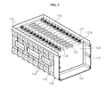
- FIG. 1 is a perspective view of a battery pack according to an embodiment of the present invention.
- the battery pack 100 may include a housing 110 accommodating a plurality of battery cells therein, an upper cover or second cover 120 covering an upper portion of the housing 110, and a front cover 130 covering a front portion of the housing 110.
- a plurality of reinforcement portions 113 may protrude from an outer surface of the housing 110 for the purpose of increasing the strength of the housing 110.
- the upper cover 120 may be coupled to the housing 110 by a plurality of bolts 121
- the front cover 130 may also be coupled to the housing 110 by the plurality of bolts 131.
- the front cover 130 may include a connector 132 electrically connected to an external device (e.g., a charger or a load).
- a handle 133 may be combined with the front cover 130 to provide for enhanced portability of the battery pack 100.
- a handle groove 134 for accommodating the handle 133 may be formed in the front cover 130.
- FIG. 2 is a perspective view illustrating a state in which an upper cover and a front cover are removed from the battery pack shown in FIG. 1 .
- the housing 110 includes a bottom portion 111, and three sidewalls 112 connected to the bottom portion 111.
- the three sidewalls 112 upwardly extend from three edges of the bottom portion 111 and the plurality of battery cells are accommodated in an inner space formed by the bottom portion 111 and the three sidewalls 112.
- the housing 110 is configured such that its front and upper portions are open.
- the middle cover 140 includes a substantially plate-shaped body 141, a bus bar seating portion 142 formed on the body 141 to allow a plurality of bus bars 174 to be seated thereon, and a plurality of gas release guides 143 formed at locations generally corresponding to safety vents of the battery cells on the body 141.
- the bus bars 174 electrically connect terminals 171 of adjacent battery cells to each other.
- first ends of power lines 161 a and 161 b are connected to individual bus bars 174.
- an end plate 150 and a BMS board 160 are located on the front of the housing 110. Second ends of the power lines 161 a and 161 b are connected to the BMS board 160. Further, the connector 132 is mechanically coupled to the BMS board 160 and electrically connected to the BMS board 160 by other power lines 162a and 162b. In addition, a plurality of electronic components for controlling charge/discharge and calculating capacities of battery cells are mounted on the BMS board 160. The BMS board 160 is coupled to the housing 110 by a plurality of bolts 163.
- FIG. 3 is a perspective view illustrating a state in which a BMS board and a connector are removed from the battery pack shown in FIG. 1 .
- the end plate 150 is connected to the front of the housing 110.
- the end plate 150 serves to securely contact the plurality of battery cells with the sidewalls 112 of the housing 110.
- the end plate 150 allows the plurality of battery cells to securely contact the sidewalls 112 of the housing 110 facing the end plate 150.
- the end plate 150 includes a plurality of holes 151 for minimizing the overall weight of the end plate 150.
- the end plate 150 is coupled to the housing 110 by a plurality of bolts 152.
- FIG. 4 is a perspective view illustrating a state in which a middle cover and an end plate are removed from the battery pack shown in FIG. 1 .
- a plurality of battery cells 170 are accommodated in an inner space formed by the bottom portion 111 and sidewalls 112 of the housing 110 in a state in which the plurality of battery cells 170 are stacked in a horizontal direction.
- Each of the plurality of battery cells 170 has one or more terminals 171 formed on its top surface.
- each of the plurality of battery cells 170 has a relatively thin safety vent 172 and a plug 173 closing an electrolyte injection hole formed on the top surface.
- the bottom surface of the battery cell 170 is closely adhered to the bottom portion 111 of the housing 110.
- two narrow side surfaces of the battery cell 170 are closely adhered to the sidewalls 112 of the housing 110 facing each other.
- the wide surface of the hindmost battery cell 170 among the plurality of battery cells 170 is closely adhered to the rear sidewall 112.
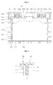
- FIG. 5 is a longitudinal section view of FIG. 1 .
- the housing 110 includes a bottom portion 111 and sidewalls 112 extending from the perimeter of the bottom portion 111.
- a plurality of reinforcement portions 113 outwardly protrude on outer surfaces of the bottom portion 111 and the sidewalls 112 for the purpose of reinforcing the strength of the housing 110.
- Extending portions 114 protruding substantially outwardly are further formed on upper ends of the sidewalls 112.
- An upper coupling portion 115 coupled to the upper cover 120 upwardly protrudes from each of the extending portions 114.
- each of the plurality of battery cells 170 has one or more terminals 171 upwardly protruding, and a bus bar 174 is coupled to each of the one or more terminals 171.
- the middle cover 140 is positioned on the top surface of the housing 110 and the plurality of battery cells 170. In other words, the middle cover 140 substantially covering the plurality of battery cells 170 is coupled between the housing 110 and the upper cover 120.
- the middle cover 140 further includes a coupling portion 144 provided at a gap or space S substantially between the sidewalls 112 of the housing 110 and each of the battery cells 170.
- the coupling portion 144 and the middle cover 140 form the shape of a "T", i.e. are preferably formed perpendicular to each other.
- the middle cover 140 further includes the coupling portion 144 downwardly fitted into the gap or space S between the sidewalls 112 of the housing 110 and the battery cell 170 for preventing the battery cells 170 from vibrating.
- the middle cover 140 includes a bus bar seating portion 142 having an internal hollow structure.
- the bus bar seating portion 142 includes an upper protrusion 142a and an internal middle protrusion 142b.
- a lower nut 171 a coupled to the terminal 171 is positioned below the internal middle protrusion 142b, and a bus bar 174 coupled to the terminal 171 and an upper nut 171 b are positioned above the internal middle protrusion 142b.
- the middle cover 140 may be fixed to the top surface of the housing 110 and the battery cell 170 by the bus bars 174 and the upper nut 171 b.
- the middle cover 140 may include the plurality of gas release guides 143 having internal hollows, by which the internal gas can be quickly guided to the outside when the safety vent 172 (refer to Fig. 4 ) is opened.
- the upper cover 120 is coupled to the upper coupling portion 115 formed in the extending portion 114 of the housing 110.
- spaced dual coupling portions 122 are formed along the perimeter of the upper cover 120 and extend downward.
- the upper coupling portion 115 of the housing 110 is coupled to the spaced dual coupling portions 122 of the upper cover 120.
- the spaced dual coupling portions 122 formed in the upper cover 120 are coupled to the upper coupling portion 115 of the housing 110, external moisture or foreign material is less likely to infiltrate the battery pack 100.
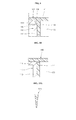
- FIG. 6 is an enlarged section view of a portion 6 shown in FIG. 5 .
- a gap or space S exists between the sidewall 112 of the housing 110 and the battery cell 170.
- the space S is created because the housing 110 is formed by plastic injection molding using a mold.
- a draft gradient may be applied to the sidewall 112 of the housing 110.
- the sidewall 112 of the housing 110 with draft gradient is formed at an angle of approximately greater than 90° with respect to the bottom portion 111, and the space S is created between the sidewall 112 and the battery cell 170 accordingly.
- the space S between the sidewall 112 and the battery cell 170 is larger closer to the upper region than further below.
- the coupling portion 144 of the middle cover 140 is combined with the space S created between the sidewall 112 and the battery cell 170.
- the space S created between the sidewall 112 and the battery cell 170 is substantially eliminated, thereby preventing the battery cell 170 from vibrating inside the housing 110.
- the battery cell 170 closely contacts the coupling portion 144 formed in the middle cover 140, thereby preventing vibration of the battery cell 170.
- the coupling portion 144 may be formed to have a substantially rectangular cross section.
- the coupling portion 144 may be formed to have a downwardly extending length of between about 1 % and about 20% of a height of the sidewall 112 (or of the battery cell 170).
- the vibration of the battery cell 170 is suppressed most efficiently.
- the downwardly extending length of the coupling portion 144 is less than 1 % of the height of the sidewall 112, the coupling portion 144 may deviate from the space S between the sidewall 112 and the battery cell 170, rather than being combined therewith.
- the downwardly extending length of the coupling portion 144 is greater than 20% of the height of the sidewall 112, the coupling portion 144 may not be properly combined with the space S between the sidewall 112 and the battery cell 170.
- a thickness of the coupling portion 144 may be the same as or slightly greater than a width of the space S between the sidewall 112 and the battery cell 170 where the coupling portion 144 is to be assembled. This may hold for all cross-sections of the coupling portion 144 along its height. Practically, the coupling portion 144 is formed to have a thickness slightly greater than the width of the space S, so that the coupling portion 144 may be combined with the space S in a forced fitting type or interference fit. Therefore, the battery cell 170 comes into closer contact with the coupling portion 144, and vibration of the battery cell 170 can be suppressed more efficiently.
- FIGS. 7A and 7B are section views illustrating modifications of coupling portions formed on the middle cover
- FIG. 8 is a perspective view illustrating a bottom surface of the middle cover in the battery pack shown in FIG. 1 .
- coupling portions 244 and 344 of middle covers 240 and 340 may be formed to have a substantially inverted trapezoidal section and a substantially inverted triangular section, respectively.
- thicknesses of the coupling portions 244 and 344 decrease, preferably gradually, in the direction away from an upper end to a lower end. Accordingly, the coupling portions 244 and 344 are easily guided into the space between the sidewall 112 of the housing 110 and the battery cell 170.
- the cross-sectional shape of the coupling portions is not limited to those described herein, but rather may be of any suitable shape to close a gap between the battery module (i.e., the plurality of battery cells 170) and the housing 110.
- the coupling portion 144 is formed along the perimeter of the body 141 of the middle cover 140.
- the coupling portion 144 may be formed in at least three sides of the perimeter of the body 141. Therefore, the coupling portion 144 is combined with the three-sided space formed between the at least three sidewall of the housing and the battery cell.
- a plurality of bus bar seating portions 142 each having a hollow and a plurality of gas release guides 143 each having a hollow are formed in the body 141 formed at an interior area of the coupling portion 144.
- a plurality of auxiliary coupling portions 145 of a substantially triangular shape are further formed at the exterior area of the coupling portion 144.
- the auxiliary coupling portions 145 are formed in a direction substantially perpendicular to a lengthwise direction of the coupling portion 144.
- the auxiliary coupling portions 145 may be formed at a pitch, and may be coupled to auxiliary coupling groove 116 provided at the sidewall 112 of the housing 110 (refer to Fig. 9 ).
- FIG. 9 is an enlarged view illustrating a connection relationship between an auxiliary coupling portion of the middle cover and an auxiliary coupling groove of the housing in the battery pack shown in FIG. 1 .
- the middle cover 140 has auxiliary coupling portions 145 of a substantially triangular shape further formed at the exterior area of the coupling portion 144.
- the auxiliary coupling portions 145 may be coupled to auxiliary coupling grooves 116 provided at the sidewall 112 of the housing 110.
- the auxiliary coupling portions 145 are formed to extend in a different direction compared to the coupling portion, preferably are formed perpendicular to the coupling portion.
- the coupling portion 144 of the middle cover 140 is combined with the space between the sidewall 112 of the housing 110, and the auxiliary coupling portions 145 of the middle cover 140 are coupled to the auxiliary coupling grooves 116 formed on the sidewall 112 of the housing 110, a coupling strength between the housing 110 and the middle cover 140 is further increased.
- the shape of the auxiliary coupling portion 145 is not limited to the shapes described here, but rather may be of any appropriate shape to engage a corresponding groove.
- FIG. 10 is a section view illustrating a coupling portion coupled between a battery cell and a housing in a battery pack according to another embodiment of the present invention.
- the coupling portion 444 and the middle cover 440 are not formed integrally with each other but rather are formed discretely from each other as separate components.
- the discrete coupling portion 444 is first combined with the space between the sidewall 112 of the housing 110 and the battery cell 170, and the middle cover 440 is then seated thereon.
- the discrete coupling portion 444 may also be formed to have a substantially rectangular cross section. The length and width of the discrete coupling portion 444 are substantially the same as those described above, and detailed descriptions thereabout will not be given.
- FIGS. 11A through 11D are section views illustrating alternative modifications of coupling portions.
- discrete coupling portions 544, 644, 744, and 844 may be formed to have shapes of an inverted trapezoid, an inverted triangle, a circle, and an oval, respectively.
- the inverted trapezoidal or the inverted triangular shaped coupling portion 544, 644 may be easily fitted into the space between the housing 110 and the battery cell 170.
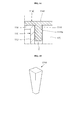
- FIG. 12 is a section view exaggeratedly illustrating a relationship between a bottom portion and sidewalls of the housing in the battery pack shown in FIG. 1 .
- the housing 110 is formed such that the bottom portion 111 and the sidewall 112 are disposed at an angle ranging from approximately 91 °to approximately 95°, instead of 90°, with respect to each other.
- a draft gradient is applied to the sidewall of the housing 110.
- the draft gradient is generally in the range of approximately 1° to approximately 5°. Accordingly, the sidewall 112 of the housing 110 tapers downward, creating a space between the sidewall 112 of the housing 110 and the battery cell 170.
- the housing 110 is formed by injection molding a plastic resin using a mold.
- the plastic resin may be at least one selected from the group consisting of Acrylonitrile-Butadience-Stryene (ABS), Polyamide (PA), PolyCarbonate (PC), PolyChloroTriFluoroethylene (PCTFE), Poly DiAllyl Phthalate (PDAP), Poly Ethylene (PE), Poly Ethylene TerePhthalate (PETP), Phenol-Formaldehyde (PF), Polyisobutylene (PIB), Poly Methyl MethAcrylate (PMMA), Polyoxymethylene (POM); Polyformaldehyde (PF), PolyPropylene (PP), PolyStyrene (PS), PolyTetraFluoroEthylene (PTFE), Polyurethane (PUR), Poly Vinyl Acetate (PVAC), Poly Vinyl Alcohol (PVA), Poly Vinyl Butyral (PVB), Poly Vinyl Chloride (PVC), Poly Vinyl Chlor
- FIG. 13 is a perspective view illustrating a bottom surface of a middle cover in a battery pack according to another embodiment of the present invention.
- the middle cover 940 includes a plurality of spaced coupling portions 944.
- the coupling portions 944 are generally formed on at least three sides of the perimeter of the body 141 of the middle cover 940.
- the coupling portions 944 are formed to be separated or spaced from each other. Therefore, a gap or space is created between two adjacent coupling portions 944.
- each of the coupling portions may include an auxiliary coupling portion 145.
- FIG. 13 illustrates the coupling portions 944 extending from the body 141 of the middle cover 940
- the coupling portions 944 may also be formed to be separate from and spaced from the body 141.
- the coupling portions 944 are combined with the gap created between each of sidewalls of a housing and a battery cell, thereby preventing the battery cells from vibrating inside the housing.
- FIG. 14 is a sectional view illustrating a modification of a coupling portion formed in the middle cover.
- the coupling portion 1144 includes a plurality of protrusions, irregularities or embossed portions 1144a on its surface.
- the plurality of protrusions, irregularities or embossed portions 1144a protrude from the surface of the coupling portion 1144, thereby allowing the coupling portion 1144 to be more closely adhered to a space S between a sidewall 112 and a battery cell 170.
- FIG. 14 illustrates the coupling portion 1144 formed to extend from a body 1141 of a middle cover 1140, the coupling portion 1144 may also be formed to be separate from and spaced from the body 1141.
- FIG. 15 is a sectional view illustrating a coupling portion or a wedge coupled between a battery cell and a housing in a battery pack according to another embodiment of the present invention.
- the coupling portion 1244 may be a wedge formed to be separate from a body of a middle cover.
- the coupling portion 1244 may be a wedge that tapers downwardly (as shown in FIG. 15 ).
- a plurality of coupling portions 1244 may be included in the battery pack, each shaped of a wedge to be fitted into a space between a sidewall of the housing and the battery cell. Therefore, the plurality of coupling portions 1244 or wedges may prevent the battery cell located at an interior area of the housing from vibrating.
- FIG. 16 is a sectional view illustrating a coupling portion or a wedge coupled between a battery cell and a housing in a battery pack according to another embodiment of the present invention.
- the coupling portion 1344 may be a wedge including a first area 1344a that tapers downwardly, and a second area that laterally protrudes from the first area 1344a in a step configuration and then tapers downwardly.
- a plurality of coupling portions or wedges 1344 may be included in the battery pack to be fitted into a space between the sidewall of the housing and a battery cell.
- each of the coupling portions 1344 or wedges includes the second area 1344b laterally protruding from the first area 1344a.
Landscapes
- Chemical & Material Sciences (AREA)
- Chemical Kinetics & Catalysis (AREA)
- Electrochemistry (AREA)
- General Chemical & Material Sciences (AREA)
- Battery Mounting, Suspending (AREA)
- Connection Of Batteries Or Terminals (AREA)
- Gas Exhaust Devices For Batteries (AREA)
Abstract
Description
- An embodiment of the present invention relates to a battery pack.
- In general, a medium-sized battery pack including a plurality of battery cells is primarily used as a power source of an electric bicycle or an electric motorcycle. The battery pack includes a plurality of rechargeable battery cells, a housing for accommodating the plurality of rechargeable battery cells, and a battery monitoring system (BMS) board for monitoring the plurality of rechargeable battery cells.
- The battery cells are typically lithium ion batteries, lithium polymer batteries, or lithium ion polymer batteries, and the housing may be made of a plastic-injected material. In addition, the BMS board is electrically connected to the battery cells to control charge and discharge of the battery cells and to calculate the capacities of the battery cells. Further, the BMS board includes a connector to be electrically connected to an external device (e.g., a charger or a load).
- Embodiments of the present invention provide a battery pack configured to prevent or minimize a plurality of rechargeable battery cells from vibrating inside a housing.
- Accordingly, a battery pack is provided comprising at least one battery cell and a housing comprising a bottom plate and a plurality of side walls, wherein the battery cell is accommodated in the space formed by the side walls and the bottom portion. A coupling portion is further provided in a gap between at least one side wall of the housing and the battery cell.
- According to the invention, the coupling portion is combined with or inserted into the gap or space between the sidewalls of the housing and each of the battery cells, thereby preventing the battery cells from vibrating inside the housing.
- In other words, the plurality of battery cells securely contact with the coupling portion, thereby preventing the battery cells from vibrating inside the housing.
- The coupling portion extends from a top surface of the battery cell towards the bottom plate of the housing. Additionally or alternatively, the coupling portion contacts the at least one side wall of the housing (110). It may additionally or alternatively contact the battery cell.
- The battery cell is preferably covered by a first or middle cover having a substantially plate-shaped first cover body and the coupling portion preferably extends in a direction away from the first cover body, preferably forming a "T" with the body.
- The first cover and the coupling portion may be connected to each other, preferably are formed integrally with each other.
- The housing preferably further comprises a second or top cover and wherein the first cover is arranged between the battery cell and the second cover.
- At least one side wall extends from the bottom of the housing at an angle of more than 90°, preferably between 91 ° and 95°, such that the size of the gap between the side wall and the battery cell increases from the bottom to the top of the housing. The gradient is applied to facilitate extraction of the housing from a mold.
- The length of the coupling portion is preferably between 1 % and 20% of the height of a side wall. Advantageously, thereby the coupling portion is properly combined with the space between the sidewall and the battery cell.
- A cross-section of the coupling portion in an unassembled state is greater than or equal to the cross-section of the gap. This allows advantageously the coupling portion to be force fitted into the gap.
- A cross-section of the coupling portion is formed to substantially have at least one of the following shapes: a rectangle, a trapezoid, a triangle, a circle, an oval or a combination thereof.
- The thickness of the coupling portion is decreasing in a direction towards the bottom plate of the housing, preferably gradually decreasing. This allows to easily guide the coupling portion into the gap.
- The coupling portion is formed to extend along at least three sides of the housing, preferably along the at least three sides of the perimeter of the body of the first cover.
- The coupling portion extends continuously along the perimeter of the body of the first cover.
- The coupling portion comprises a plurality of spaced apart coupling elements.
- An auxiliary coupling portion is provided crossing the coupling portion, preferably extending perpendicular to the coupling portion, and wherein a coupling groove is formed in respective side walls of the housing to receive the auxiliary coupling portion.
- The coupling portion comprises protrusions, cut-outs or embossed portions, and/or is formed by a plurality of wedges. This allows the coupling portion to be more closely adhered to the space between a sidewall and the battery cells.
-
FIG. 1 is a perspective view of a battery pack according to an embodiment of the present invention; -
FIG. 2 is a perspective view illustrating a state in which an upper cover and a front cover are removed from the battery pack shown inFIG. 1 ; -
FIG. 3 is a perspective view illustrating a state in which a BMS board and a connector are removed from the battery pack shown inFIG. 1 ; -
FIG. 4 is a perspective view illustrating a state in which a middle cover and an end plate are removed from the battery pack shown inFIG. 1 ; -
FIG. 5 is a longitudinal section view ofFIG. 1 ; -
FIG. 6 is an enlarged section view of aportion 6 shown inFIG. 5 ; -
FIGS. 7A and 7B are section views illustrating modifications of coupling portions formed on the middle cover; -
FIG. 8 is a perspective view illustrating a bottom surface of the middle cover in the battery pack shown inFIG. 1 ; -
FIG. 9 is an enlarged view illustrating a connection relationship between an auxiliary coupling portion of the middle cover and an auxiliary coupling groove of the housing in the battery pack shown inFIG. 1 ; -
FIG. 10 is a section view illustrating a coupling portion coupled between a battery cell and a housing in a battery pack according to another embodiment of the present invention; -
FIGS. 11A through 11D are section views illustrating alternative modifications of coupling portions; -
FIG. 12 is a schematic section view exaggeratedly illustrating a relationship between a bottom portion and sidewalls of the housing in the battery pack shown inFIG. 1 . -
FIG. 13 is a perspective view illustrating a bottom surface of a middle cover in a battery pack according to another embodiment of the present invention; -
FIG. 14 is a sectional view illustrating a modification of a coupling portion formed in the middle cover; -
FIG. 15 is a sectional view illustrating a coupling portion or a wedge coupled between a battery cell and a housing in a battery pack according to another embodiment of the present invention; and -
FIG. 16 is a sectional view illustrating a coupling portion or a wedge coupled between a battery cell and a housing in a battery pack according to another embodiment of the present invention. - Example embodiments will now be described more fully hereinafter with reference to the accompanying drawings; however, they may be embodied in different forms and should not be construed as limited to the embodiments set forth herein. Rather, these embodiments are provided so that this disclosure will be thorough and complete, and will fully convey the scope of the invention to those skilled in the art.
-
FIG. 1 is a perspective view of a battery pack according to an embodiment of the present invention. - As shown in
FIG. 1 , thebattery pack 100 may include ahousing 110 accommodating a plurality of battery cells therein, an upper cover orsecond cover 120 covering an upper portion of thehousing 110, and afront cover 130 covering a front portion of thehousing 110. - Here, a plurality of
reinforcement portions 113 may protrude from an outer surface of thehousing 110 for the purpose of increasing the strength of thehousing 110. In addition, theupper cover 120 may be coupled to thehousing 110 by a plurality ofbolts 121, and thefront cover 130 may also be coupled to thehousing 110 by the plurality ofbolts 131. Further, thefront cover 130 may include aconnector 132 electrically connected to an external device (e.g., a charger or a load). Moreover, ahandle 133 may be combined with thefront cover 130 to provide for enhanced portability of thebattery pack 100. Additionally, ahandle groove 134 for accommodating thehandle 133 may be formed in thefront cover 130. -
FIG. 2 is a perspective view illustrating a state in which an upper cover and a front cover are removed from the battery pack shown inFIG. 1 . - As shown in
FIG. 2 , in the battery pack according to an embodiment of the present invention, thehousing 110 includes abottom portion 111, and threesidewalls 112 connected to thebottom portion 111. - Here, the three
sidewalls 112 upwardly extend from three edges of thebottom portion 111 and the plurality of battery cells are accommodated in an inner space formed by thebottom portion 111 and the threesidewalls 112. In addition, thehousing 110 is configured such that its front and upper portions are open. - An
upper coupling portion 115 coupled to theupper cover 120 protrudes from top ends of the threesidewalls 112. In addition, the middle cover offirst cover 140 is positioned on a top surface of thehousing 110, that is, at the interior of theupper coupling portion 115. The plurality of battery cells are positioned in the inner space formed by themiddle cover 140 and thehousing 110. Themiddle cover 140 includes a substantially plate-shapedbody 141, a busbar seating portion 142 formed on thebody 141 to allow a plurality ofbus bars 174 to be seated thereon, and a plurality of gas release guides 143 formed at locations generally corresponding to safety vents of the battery cells on thebody 141. Here, the bus bars 174 electrically connectterminals 171 of adjacent battery cells to each other. In addition, first ends ofpower lines - In one embodiment, an
end plate 150 and aBMS board 160 are located on the front of thehousing 110. Second ends of thepower lines BMS board 160. Further, theconnector 132 is mechanically coupled to theBMS board 160 and electrically connected to theBMS board 160 byother power lines BMS board 160. TheBMS board 160 is coupled to thehousing 110 by a plurality ofbolts 163. -
FIG. 3 is a perspective view illustrating a state in which a BMS board and a connector are removed from the battery pack shown inFIG. 1 . - As shown in
FIG. 3 , theend plate 150 is connected to the front of thehousing 110. Theend plate 150 serves to securely contact the plurality of battery cells with thesidewalls 112 of thehousing 110. In particular, theend plate 150 allows the plurality of battery cells to securely contact thesidewalls 112 of thehousing 110 facing theend plate 150. - In addition, the
end plate 150 includes a plurality ofholes 151 for minimizing the overall weight of theend plate 150. Theend plate 150 is coupled to thehousing 110 by a plurality ofbolts 152. -
FIG. 4 is a perspective view illustrating a state in which a middle cover and an end plate are removed from the battery pack shown inFIG. 1 . - As shown in
FIG. 4 , a plurality ofbattery cells 170 are accommodated in an inner space formed by thebottom portion 111 andsidewalls 112 of thehousing 110 in a state in which the plurality ofbattery cells 170 are stacked in a horizontal direction. Each of the plurality ofbattery cells 170 has one ormore terminals 171 formed on its top surface. In addition, each of the plurality ofbattery cells 170 has a relativelythin safety vent 172 and aplug 173 closing an electrolyte injection hole formed on the top surface. - The bottom surface of the
battery cell 170 is closely adhered to thebottom portion 111 of thehousing 110. In addition, two narrow side surfaces of thebattery cell 170 are closely adhered to thesidewalls 112 of thehousing 110 facing each other. Further, the wide surface of thehindmost battery cell 170 among the plurality ofbattery cells 170 is closely adhered to therear sidewall 112. -
FIG. 5 is a longitudinal section view ofFIG. 1 . - As shown in
FIG. 5 , thehousing 110 includes abottom portion 111 andsidewalls 112 extending from the perimeter of thebottom portion 111. In addition, a plurality ofreinforcement portions 113 outwardly protrude on outer surfaces of thebottom portion 111 and thesidewalls 112 for the purpose of reinforcing the strength of thehousing 110. Extendingportions 114 protruding substantially outwardly are further formed on upper ends of thesidewalls 112. Anupper coupling portion 115 coupled to theupper cover 120 upwardly protrudes from each of the extendingportions 114. - Meanwhile, as described above, a plurality of
battery cells 170 are accommodated in an inner space formed by thebottom portion 111 and the threesidewalls 112 of thehousing 110. In addition, as described above, each of the plurality ofbattery cells 170 has one ormore terminals 171 upwardly protruding, and abus bar 174 is coupled to each of the one ormore terminals 171. - The
middle cover 140 is positioned on the top surface of thehousing 110 and the plurality ofbattery cells 170. In other words, themiddle cover 140 substantially covering the plurality ofbattery cells 170 is coupled between thehousing 110 and theupper cover 120. Themiddle cover 140 further includes acoupling portion 144 provided at a gap or space S substantially between thesidewalls 112 of thehousing 110 and each of thebattery cells 170. Preferably, thecoupling portion 144 and themiddle cover 140 form the shape of a "T", i.e. are preferably formed perpendicular to each other. In other words, themiddle cover 140 further includes thecoupling portion 144 downwardly fitted into the gap or space S between thesidewalls 112 of thehousing 110 and thebattery cell 170 for preventing thebattery cells 170 from vibrating. - Further, the
middle cover 140 includes a busbar seating portion 142 having an internal hollow structure. The busbar seating portion 142 includes anupper protrusion 142a and an internalmiddle protrusion 142b. Alower nut 171 a coupled to the terminal 171 is positioned below the internalmiddle protrusion 142b, and abus bar 174 coupled to the terminal 171 and anupper nut 171 b are positioned above the internalmiddle protrusion 142b. Thus, themiddle cover 140 may be fixed to the top surface of thehousing 110 and thebattery cell 170 by the bus bars 174 and theupper nut 171 b. In addition, themiddle cover 140 may include the plurality of gas release guides 143 having internal hollows, by which the internal gas can be quickly guided to the outside when the safety vent 172 (refer toFig. 4 ) is opened. - In addition, the
upper cover 120 is coupled to theupper coupling portion 115 formed in the extendingportion 114 of thehousing 110. To this end, spaceddual coupling portions 122 are formed along the perimeter of theupper cover 120 and extend downward. In other words, theupper coupling portion 115 of thehousing 110 is coupled to the spaceddual coupling portions 122 of theupper cover 120. As described above, since the spaceddual coupling portions 122 formed in theupper cover 120 are coupled to theupper coupling portion 115 of thehousing 110, external moisture or foreign material is less likely to infiltrate thebattery pack 100. -
FIG. 6 is an enlarged section view of aportion 6 shown inFIG. 5 . - As shown in
FIG. 6 , a gap or space S exists between thesidewall 112 of thehousing 110 and thebattery cell 170. The space S is created because thehousing 110 is formed by plastic injection molding using a mold. In detail, after the injection-molding of thehousing 110, in order to easily extract thehousing 110 from the mold, a draft gradient may be applied to thesidewall 112 of thehousing 110. Thesidewall 112 of thehousing 110 with draft gradient is formed at an angle of approximately greater than 90° with respect to thebottom portion 111, and the space S is created between thesidewall 112 and thebattery cell 170 accordingly. In particular, the space S between thesidewall 112 and thebattery cell 170 is larger closer to the upper region than further below. - As described above, according to the present invention, with the draft gradient, the
coupling portion 144 of themiddle cover 140 is combined with the space S created between thesidewall 112 and thebattery cell 170. In such a manner that the space S created between thesidewall 112 and thebattery cell 170 is substantially eliminated, thereby preventing thebattery cell 170 from vibrating inside thehousing 110. In other words, thebattery cell 170 closely contacts thecoupling portion 144 formed in themiddle cover 140, thereby preventing vibration of thebattery cell 170. - The
coupling portion 144 may be formed to have a substantially rectangular cross section. In addition, thecoupling portion 144 may be formed to have a downwardly extending length of between about 1 % and about 20% of a height of the sidewall 112 (or of the battery cell 170). When the downwardly extending length of thecoupling portion 144 is between about 1% and about 20% of the height of thesidewall 112, the vibration of thebattery cell 170 is suppressed most efficiently. If the downwardly extending length of thecoupling portion 144 is less than 1 % of the height of thesidewall 112, thecoupling portion 144 may deviate from the space S between thesidewall 112 and thebattery cell 170, rather than being combined therewith. On the other hand, if the downwardly extending length of thecoupling portion 144 is greater than 20% of the height of thesidewall 112, thecoupling portion 144 may not be properly combined with the space S between thesidewall 112 and thebattery cell 170. - In a non-assembled state, a thickness of the
coupling portion 144 may be the same as or slightly greater than a width of the space S between thesidewall 112 and thebattery cell 170 where thecoupling portion 144 is to be assembled. This may hold for all cross-sections of thecoupling portion 144 along its height. Practically, thecoupling portion 144 is formed to have a thickness slightly greater than the width of the space S, so that thecoupling portion 144 may be combined with the space S in a forced fitting type or interference fit. Therefore, thebattery cell 170 comes into closer contact with thecoupling portion 144, and vibration of thebattery cell 170 can be suppressed more efficiently. -
FIGS. 7A and 7B are section views illustrating modifications of coupling portions formed on the middle cover, andFIG. 8 is a perspective view illustrating a bottom surface of the middle cover in the battery pack shown inFIG. 1 . - As shown in
FIGS. 7A and 7B ,coupling portions coupling portions coupling portions sidewall 112 of thehousing 110 and thebattery cell 170. In other words, since each of thecoupling portions coupling portion 144 is easily inserted into the space. As will be appreciated, the cross-sectional shape of the coupling portions is not limited to those described herein, but rather may be of any suitable shape to close a gap between the battery module (i.e., the plurality of battery cells 170) and thehousing 110. - As shown in
FIG. 8 , thecoupling portion 144 is formed along the perimeter of thebody 141 of themiddle cover 140. For example, thecoupling portion 144 may be formed in at least three sides of the perimeter of thebody 141. Therefore, thecoupling portion 144 is combined with the three-sided space formed between the at least three sidewall of the housing and the battery cell. In addition, a plurality of busbar seating portions 142 each having a hollow and a plurality of gas release guides 143 each having a hollow are formed in thebody 141 formed at an interior area of thecoupling portion 144. - In one embodiment, a plurality of
auxiliary coupling portions 145 of a substantially triangular shape are further formed at the exterior area of thecoupling portion 144. In other words, theauxiliary coupling portions 145 are formed in a direction substantially perpendicular to a lengthwise direction of thecoupling portion 144. Theauxiliary coupling portions 145 may be formed at a pitch, and may be coupled toauxiliary coupling groove 116 provided at thesidewall 112 of the housing 110 (refer toFig. 9 ). -
FIG. 9 is an enlarged view illustrating a connection relationship between an auxiliary coupling portion of the middle cover and an auxiliary coupling groove of the housing in the battery pack shown inFIG. 1 . - As shown in
FIG. 9 , themiddle cover 140 hasauxiliary coupling portions 145 of a substantially triangular shape further formed at the exterior area of thecoupling portion 144. Theauxiliary coupling portions 145 may be coupled toauxiliary coupling grooves 116 provided at thesidewall 112 of thehousing 110. Theauxiliary coupling portions 145 are formed to extend in a different direction compared to the coupling portion, preferably are formed perpendicular to the coupling portion. Therefore, according to the present invention, since thecoupling portion 144 of themiddle cover 140 is combined with the space between thesidewall 112 of thehousing 110, and theauxiliary coupling portions 145 of themiddle cover 140 are coupled to theauxiliary coupling grooves 116 formed on thesidewall 112 of thehousing 110, a coupling strength between thehousing 110 and themiddle cover 140 is further increased. As will be appreciated, the shape of theauxiliary coupling portion 145 is not limited to the shapes described here, but rather may be of any appropriate shape to engage a corresponding groove. -
FIG. 10 is a section view illustrating a coupling portion coupled between a battery cell and a housing in a battery pack according to another embodiment of the present invention. - As shown in
FIG. 10 according to another embodiment of the present invention, thecoupling portion 444 and themiddle cover 440 are not formed integrally with each other but rather are formed discretely from each other as separate components. Thus, thediscrete coupling portion 444 is first combined with the space between thesidewall 112 of thehousing 110 and thebattery cell 170, and themiddle cover 440 is then seated thereon. Here, thediscrete coupling portion 444 may also be formed to have a substantially rectangular cross section. The length and width of thediscrete coupling portion 444 are substantially the same as those described above, and detailed descriptions thereabout will not be given. -
FIGS. 11A through 11D are section views illustrating alternative modifications of coupling portions. - As shown in
FIGS. 11A through 11D ,discrete coupling portions shaped coupling portion housing 110 and thebattery cell 170. -
FIG. 12 is a section view exaggeratedly illustrating a relationship between a bottom portion and sidewalls of the housing in the battery pack shown inFIG. 1 . - As shown in
FIG.12 , thehousing 110 is formed such that thebottom portion 111 and thesidewall 112 are disposed at an angle ranging from approximately 91 °to approximately 95°, instead of 90°, with respect to each other. In other words, in thebattery pack 100, in order to facilitate extraction of thehousing 110 from a mold during an injection-molding operation, a draft gradient is applied to the sidewall of thehousing 110. The draft gradient is generally in the range of approximately 1° to approximately 5°. Accordingly, thesidewall 112 of thehousing 110 tapers downward, creating a space between thesidewall 112 of thehousing 110 and thebattery cell 170. - The
housing 110 is formed by injection molding a plastic resin using a mold. The plastic resin may be at least one selected from the group consisting of Acrylonitrile-Butadience-Stryene (ABS), Polyamide (PA), PolyCarbonate (PC), PolyChloroTriFluoroethylene (PCTFE), Poly DiAllyl Phthalate (PDAP), Poly Ethylene (PE), Poly Ethylene TerePhthalate (PETP), Phenol-Formaldehyde (PF), Polyisobutylene (PIB), Poly Methyl MethAcrylate (PMMA), Polyoxymethylene (POM); Polyformaldehyde (PF), PolyPropylene (PP), PolyStyrene (PS), PolyTetraFluoroEthylene (PTFE), Polyurethane (PUR), Poly Vinyl Acetate (PVAC), Poly Vinyl Alcohol (PVA), Poly Vinyl Butyral (PVB), Poly Vinyl Chloride (PVC), Poly Vinyl Chloride Acetate (PVCA), Poly VinyliDene Chloride (PVDC), Poly Vinyl Fluoride (PVF), Poly Vinyl ForMal (PVFM), and equivalents thereof, but aspects of the invention are not limited to those listed herein as the material of thehousing 110. Preferably, thecoupling portions 144 are formed of the same material as the housing. -
FIG. 13 is a perspective view illustrating a bottom surface of a middle cover in a battery pack according to another embodiment of the present invention. - As shown in
FIG. 13 , themiddle cover 940 includes a plurality of spacedcoupling portions 944. In other words, thecoupling portions 944 are generally formed on at least three sides of the perimeter of thebody 141 of themiddle cover 940. In one embodiment, thecoupling portions 944 are formed to be separated or spaced from each other. Therefore, a gap or space is created between twoadjacent coupling portions 944. Additionally, each of the coupling portions may include anauxiliary coupling portion 145. - Although
FIG. 13 illustrates thecoupling portions 944 extending from thebody 141 of themiddle cover 940, thecoupling portions 944 may also be formed to be separate from and spaced from thebody 141. - In such a manner, the
coupling portions 944 are combined with the gap created between each of sidewalls of a housing and a battery cell, thereby preventing the battery cells from vibrating inside the housing. -
FIG. 14 is a sectional view illustrating a modification of a coupling portion formed in the middle cover. - As shown in
FIG. 14 , thecoupling portion 1144 includes a plurality of protrusions, irregularities or embossedportions 1144a on its surface. The plurality of protrusions, irregularities or embossedportions 1144a protrude from the surface of thecoupling portion 1144, thereby allowing thecoupling portion 1144 to be more closely adhered to a space S between asidewall 112 and abattery cell 170. - Although
FIG. 14 illustrates thecoupling portion 1144 formed to extend from abody 1141 of amiddle cover 1140, thecoupling portion 1144 may also be formed to be separate from and spaced from thebody 1141. -
FIG. 15 is a sectional view illustrating a coupling portion or a wedge coupled between a battery cell and a housing in a battery pack according to another embodiment of the present invention. - As shown in
FIG. 15 , thecoupling portion 1244 may be a wedge formed to be separate from a body of a middle cover. For example, thecoupling portion 1244 may be a wedge that tapers downwardly (as shown inFIG. 15 ). A plurality ofcoupling portions 1244 may be included in the battery pack, each shaped of a wedge to be fitted into a space between a sidewall of the housing and the battery cell. Therefore, the plurality ofcoupling portions 1244 or wedges may prevent the battery cell located at an interior area of the housing from vibrating. -
FIG. 16 is a sectional view illustrating a coupling portion or a wedge coupled between a battery cell and a housing in a battery pack according to another embodiment of the present invention. - As shown in
FIG. 16 , thecoupling portion 1344 may be a wedge including afirst area 1344a that tapers downwardly, and a second area that laterally protrudes from thefirst area 1344a in a step configuration and then tapers downwardly. A plurality of coupling portions orwedges 1344 may be included in the battery pack to be fitted into a space between the sidewall of the housing and a battery cell. Particularly, each of thecoupling portions 1344 or wedges includes thesecond area 1344b laterally protruding from thefirst area 1344a. Thus, once thecoupling portions 1344 or wedges are fitted into the space between the sidewall of the housing and the battery cell, they are not readily loosened from the space, thereby preventing the battery cell located at an interior area of the housing from vibrating. Although the battery pack according to exemplary embodiments of the present invention have been described for illustrative purposes, those skilled in the art will appreciate that various modifications are possible without departing from the scope of the invention as disclosed in the appended claims.
Claims (15)
- A battery pack (100) comprising:at least one battery cell (170); anda housing (110) comprising a bottom plate (111 ) and a plurality of side walls (112), wherein the battery cell (170) is accommodated in the space formed by the side walls (112) and the bottom portion (111 );characterized in thata coupling portion (144) is provided in a gap (S) between at least one side wall (112) of the housing (110) and the battery cell (170).
- The battery pack (100) of claim 1, wherein the coupling portion (144)
extends from a top surface of the battery cell (170) towards the bottom plate (111) of the housing (110); and/or
contacts the at least one side wall (112) of the housing (110); and/or contacts the battery cell (170). - The battery pack (100) of claim 1 or 2, wherein the battery cell (170) is covered by a first cover (140) having a substantially plate-shaped first cover body (141) and wherein the coupling portion (144) extends in a direction away from the first cover body (141 ), preferably forming a "T" with the body (141).
- The battery pack (100) of claim 3, wherein the first cover (140) and the coupling portion (144) are connected to each other, preferably are formed integrally with each other.
- The battery pack (100) of one of the previous claims, wherein the housing (110) further comprises a second cover (120) and wherein the first cover (140) is arranged between the battery cell (170) and the second cover (120).
- The battery pack (100) of one of the previous claims, wherein at least one side wall (112) extends from the bottom (111) of the housing (110) at an angle of more than 90°, preferably between 91 ° and 95°, such that the size of the gap (S) between the side wall (112) and the battery cell (170) increases from the bottom to the top of the housing (110).
- The battery pack (100) of one of the previous claims, wherein the length of the coupling portion (144) is between 1% and 20% of the height of a side wall (112).
- The battery pack (100) of one of the previous claims, wherein a cross-section of the coupling portion (144) in an unassembled state is greater than or equal to the cross-section of the gap (S).
- The battery pack (100) of one of the previous claims, wherein a cross-section of the coupling portion (144) is formed to substantially have at least one of the following shapes: a rectangle, a trapezoid, a triangle, a circle, an oval or a combination thereof.
- The battery pack (100) of one of the previous claims, wherein the thickness of the coupling portion (144) is decreasing in a direction towards the bottom plate (111) of the housing (110), preferably gradually decreasing.
- The battery pack (100) of one of the previous claims, wherein the coupling portion (144) is formed to extend along at least three sides of the housing (110), preferably along the at least three sides of the perimeter of the body (141) of the first cover (140).
- The battery pack (100) of one of the previous claims, wherein the coupling portion (144) extends continuously along the perimeter of the body (141) of the first cover (140).
- The battery pack (100) of one of the previous claims 1 to 11, wherein the coupling portion (144) comprises a plurality of spaced apart coupling elements.
- The battery pack (100) of one of the previous claims, wherein an auxiliary coupling portion (145) is provided crossing the coupling portion (144), preferably extending perpendicular to the coupling portion (144), and wherein a coupling groove (116) is formed in respective side walls (112) of the housing (110) to receive the auxiliary coupling portion (145).
- The battery pack (100) of one of the previous claims, wherein the coupling portion (1144, 1244, 1344) comprises protrusions, cut-outs or embossed portions, and/or is formed by a plurality of wedges.
Applications Claiming Priority (2)
| Application Number | Priority Date | Filing Date | Title |
|---|---|---|---|
| US34844710P | 2010-05-26 | 2010-05-26 | |
| US12/838,311 US9263713B2 (en) | 2010-05-26 | 2010-07-16 | Battery pack |
Publications (2)
| Publication Number | Publication Date |
|---|---|
| EP2390940A1 true EP2390940A1 (en) | 2011-11-30 |
| EP2390940B1 EP2390940B1 (en) | 2012-10-17 |
Family
ID=43012589
Family Applications (1)
| Application Number | Title | Priority Date | Filing Date |
|---|---|---|---|
| EP10174093A Active EP2390940B1 (en) | 2010-05-26 | 2010-08-26 | Battery pack |
Country Status (5)
| Country | Link |
|---|---|
| US (1) | US9263713B2 (en) |
| EP (1) | EP2390940B1 (en) |
| JP (1) | JP5255622B2 (en) |
| KR (1) | KR101165530B1 (en) |
| CN (1) | CN102263212B (en) |
Cited By (1)
| Publication number | Priority date | Publication date | Assignee | Title |
|---|---|---|---|---|
| EP2713417B1 (en) * | 2012-09-26 | 2023-11-22 | GS Yuasa International Ltd. | Assembled battery |
Families Citing this family (47)
| Publication number | Priority date | Publication date | Assignee | Title |
|---|---|---|---|---|
| KR101223519B1 (en) * | 2010-11-05 | 2013-01-17 | 로베르트 보쉬 게엠베하 | Battery module |
| WO2012164635A1 (en) * | 2011-06-03 | 2012-12-06 | トヨタ自動車株式会社 | Bus bar case, electric storage device, and vehicle |
| JP6107114B2 (en) | 2012-01-16 | 2017-04-05 | 株式会社Gsユアサ | Power supply |
| DE102012200980B4 (en) * | 2012-01-24 | 2023-04-20 | Robert Bosch Gmbh | Battery safety system |
| JP2013247056A (en) * | 2012-05-29 | 2013-12-09 | Auto Network Gijutsu Kenkyusho:Kk | Battery wiring module |
| KR20140046847A (en) * | 2012-10-11 | 2014-04-21 | 삼성에스디아이 주식회사 | Battery pack |
| KR101678527B1 (en) * | 2012-10-24 | 2016-11-22 | 삼성에스디아이 주식회사 | Battery pack |
| CN102969465A (en) * | 2012-11-06 | 2013-03-13 | 上海航天电源技术有限责任公司 | Lithium ion battery module with insulation and weight reduction integrated structure design for energy storage |
| KR20140094898A (en) * | 2013-01-23 | 2014-07-31 | 삼성에스디아이 주식회사 | Case for packing battery |
| DE102013201007A1 (en) * | 2013-01-23 | 2014-07-24 | Robert Bosch Gmbh | Battery module for battery system of motor car, has module housing that encapsulates the two battery units |
| US20140295235A1 (en) * | 2013-03-29 | 2014-10-02 | Samsung Sdi Co., Ltd. | Battery module |
| DE102013206503A1 (en) * | 2013-04-12 | 2014-10-16 | Robert Bosch Gmbh | Device for receiving battery cells, battery module and motor vehicle |
| JP6149490B2 (en) * | 2013-04-25 | 2017-06-21 | 株式会社Gsユアサ | Assembled battery |
| US10326175B2 (en) * | 2014-05-08 | 2019-06-18 | Lg Chem, Ltd. | Battery pack including noise reduction member |
| US10084218B2 (en) * | 2014-05-09 | 2018-09-25 | Lg Chem, Ltd. | Battery pack and method of assembling the battery pack |
| EP3128577B1 (en) | 2014-05-12 | 2019-09-04 | LG Chem, Ltd. | Battery pack including spacer |
| KR101808310B1 (en) * | 2014-12-24 | 2017-12-12 | 주식회사 엘지화학 | Compact secondary battery module integrated with BMS |
| JP6135694B2 (en) * | 2015-02-20 | 2017-05-31 | トヨタ自動車株式会社 | Car battery |
| US11309604B2 (en) * | 2015-04-13 | 2022-04-19 | Cps Technology Holdings Llc | Thermal epoxy and positioning of electrochemical cells |
| KR101826141B1 (en) | 2015-08-28 | 2018-02-06 | 삼성에스디아이 주식회사 | Rechargeable battery pack |
| CN106531912B (en) * | 2015-09-15 | 2022-07-19 | 北京普莱德新能源电池科技有限公司 | Square battery module |
| KR102133554B1 (en) * | 2016-10-21 | 2020-07-13 | 주식회사 엘지화학 | Battery pack |
| CN106410069B (en) * | 2016-11-11 | 2019-04-16 | 欣旺达电子股份有限公司 | Removable lithium battery group |
| JP7047774B2 (en) * | 2016-12-28 | 2022-04-05 | 株式会社Gsユアサ | Power storage device |
| EP3574538B1 (en) | 2017-01-27 | 2024-03-06 | CPS Technology Holdings LLC | Battery housing |
| USD855562S1 (en) * | 2017-02-24 | 2019-08-06 | Ge Global Sourcing Llc | Battery module |
| USD887968S1 (en) | 2017-03-10 | 2020-06-23 | Kabushiki Kaisha Toshiba | Battery module |
| USD884598S1 (en) | 2017-03-10 | 2020-05-19 | Kabushiki Kaisha Toshiba | Battery module |
| EP3635805B1 (en) | 2017-06-09 | 2023-09-06 | CPS Technology Holdings LLC | Lead-acid battery |
| US11936032B2 (en) | 2017-06-09 | 2024-03-19 | Cps Technology Holdings Llc | Absorbent glass mat battery |
| USD891362S1 (en) | 2017-11-13 | 2020-07-28 | Pure Watercraft, Inc. | Battery pack |
| USD884644S1 (en) | 2017-11-13 | 2020-05-19 | Pure Watercraft, Inc. | Power connector |
| US11183739B2 (en) * | 2017-11-13 | 2021-11-23 | Pure Watercraft, Inc. | Batteries for electric marine propulsion systems, and associated systems and methods |
| JP6878322B2 (en) * | 2018-01-16 | 2021-05-26 | 株式会社オートネットワーク技術研究所 | External connection busbar connection structure and external connection busbar connection method |
| CN113302791A (en) | 2018-08-21 | 2021-08-24 | 纯船舶公司 | Battery for electric marine propulsion system, and related system and method |
| JP1645537S (en) * | 2018-12-26 | 2019-11-11 | ||
| USD912614S1 (en) | 2019-01-04 | 2021-03-09 | Pure Watercraft, Inc. | Battery pack |
| KR102352296B1 (en) * | 2019-01-10 | 2022-01-14 | 주식회사 엘지에너지솔루션 | Battery Module Having Inner Plate |
| KR102381762B1 (en) * | 2019-02-21 | 2022-03-31 | 주식회사 엘지에너지솔루션 | Battery module including protection cover covering flexible printed circuit board |
| US20220149477A1 (en) * | 2019-03-19 | 2022-05-12 | Sanyo Electric Co., Ltd. | Battery module |
| US20220158294A1 (en) * | 2019-03-22 | 2022-05-19 | Sanyo Electric Co., Ltd. | Battery module |
| DE102019208570A1 (en) * | 2019-06-13 | 2020-12-17 | Volkswagen Aktiengesellschaft | Battery arrangement, vehicle or stationary system with such as well as a method for producing said battery arrangement |
| JP7484126B2 (en) * | 2019-10-23 | 2024-05-16 | 株式会社Gsユアサ | Power storage device |
| KR20210133541A (en) * | 2020-04-29 | 2021-11-08 | 주식회사 엘지에너지솔루션 | Battery module and battery pack including the same |
| BR112022014735A2 (en) * | 2020-05-27 | 2022-12-06 | Contemporary Amperex Technology Co Ltd | SECONDARY BATTERY, BATTERY MODULE AND DEVICE USING A SECONDARY BATTERY AS A POWER SOURCE |
| JP7319953B2 (en) * | 2020-10-20 | 2023-08-02 | プライムプラネットエナジー&ソリューションズ株式会社 | power storage device |
| US20230097757A1 (en) * | 2020-11-26 | 2023-03-30 | Lg Energy Solution, Ltd. | Battery module and battery pack including the same |
Citations (3)
| Publication number | Priority date | Publication date | Assignee | Title |
|---|---|---|---|---|
| US1535906A (en) * | 1924-07-12 | 1925-04-28 | Harley J Davoll | Battery holddown |
| DE19822059A1 (en) * | 1998-05-16 | 1999-11-18 | Mann & Hummel Filter | Device for accommodating and holding battery |
| US20090325049A1 (en) * | 2008-06-30 | 2009-12-31 | Lg Chem, Ltd. | Battery Mounting System |
Family Cites Families (16)
| Publication number | Priority date | Publication date | Assignee | Title |
|---|---|---|---|---|
| JP3683307B2 (en) | 1995-06-30 | 2005-08-17 | ヤマハ発動機株式会社 | Battery storage device for vehicle |
| JPH10199497A (en) | 1997-01-14 | 1998-07-31 | Yuasa Corp | Battery device |
| JP2001332235A (en) * | 2000-05-25 | 2001-11-30 | Yazaki Corp | Battery cover |
| ES2192954B1 (en) * | 2001-09-27 | 2005-03-01 | S.E. Acumulador Tudor, S.A. | BATTERY OF ELECTRIC ACCUMULATORS. |
| JP3990960B2 (en) * | 2002-08-30 | 2007-10-17 | 矢崎総業株式会社 | Battery connection plate and its mounting structure |
| JP4570888B2 (en) * | 2004-03-18 | 2010-10-27 | 富士重工業株式会社 | Power storage device |
| US20060093901A1 (en) * | 2004-10-28 | 2006-05-04 | Gun-Goo Lee | Secondary battery module and cooling apparatus for secondary battery module |
| JP2006147415A (en) | 2004-11-22 | 2006-06-08 | Daihatsu Motor Co Ltd | Battery cover |
| KR100686832B1 (en) | 2005-05-16 | 2007-02-26 | 삼성에스디아이 주식회사 | Battery pack |
| WO2006135008A1 (en) * | 2005-06-17 | 2006-12-21 | Nec Lamilion Energy, Ltd. | Electric device assembly and electric device with film outer covering |
| JP4997758B2 (en) | 2005-12-21 | 2012-08-08 | マックス株式会社 | Battery pack cooling structure |
| KR101222326B1 (en) | 2006-03-28 | 2013-01-15 | 삼성에스디아이 주식회사 | Battery Pack |
| KR100892047B1 (en) * | 2006-09-18 | 2009-04-07 | 주식회사 엘지화학 | Battery Module and Middle or Large-sized Battery Pack Containing the Same |
| JP5096038B2 (en) | 2007-05-09 | 2012-12-12 | トヨタ自動車株式会社 | Battery pack structure |
| KR100917750B1 (en) | 2007-09-17 | 2009-09-15 | 삼성에스디아이 주식회사 | Battery pack |
| JP5450115B2 (en) | 2010-01-12 | 2014-03-26 | 三洋電機株式会社 | Battery pack |
-
2010
- 2010-07-16 US US12/838,311 patent/US9263713B2/en active Active
- 2010-08-16 KR KR1020100078865A patent/KR101165530B1/en active IP Right Grant
- 2010-08-26 EP EP10174093A patent/EP2390940B1/en active Active
- 2010-12-24 JP JP2010287636A patent/JP5255622B2/en active Active
-
2011
- 2011-02-18 CN CN201110043032.6A patent/CN102263212B/en active Active
Patent Citations (3)
| Publication number | Priority date | Publication date | Assignee | Title |
|---|---|---|---|---|
| US1535906A (en) * | 1924-07-12 | 1925-04-28 | Harley J Davoll | Battery holddown |
| DE19822059A1 (en) * | 1998-05-16 | 1999-11-18 | Mann & Hummel Filter | Device for accommodating and holding battery |
| US20090325049A1 (en) * | 2008-06-30 | 2009-12-31 | Lg Chem, Ltd. | Battery Mounting System |
Cited By (1)
| Publication number | Priority date | Publication date | Assignee | Title |
|---|---|---|---|---|
| EP2713417B1 (en) * | 2012-09-26 | 2023-11-22 | GS Yuasa International Ltd. | Assembled battery |
Also Published As
| Publication number | Publication date |
|---|---|
| JP5255622B2 (en) | 2013-08-07 |
| JP2011249309A (en) | 2011-12-08 |
| KR20110129799A (en) | 2011-12-02 |
| KR101165530B1 (en) | 2012-07-16 |
| US9263713B2 (en) | 2016-02-16 |
| US20110293973A1 (en) | 2011-12-01 |
| CN102263212A (en) | 2011-11-30 |
| EP2390940B1 (en) | 2012-10-17 |
| CN102263212B (en) | 2014-06-18 |
Similar Documents
| Publication | Publication Date | Title |
|---|---|---|
| EP2390940B1 (en) | Battery pack | |
| EP2416402B1 (en) | Battery pack with reinforcement member | |
| CN110915024B (en) | Battery module, and battery pack and vehicle including the same | |
| KR101191659B1 (en) | Battery module | |
| JP7046167B2 (en) | Battery pack including pack housing | |
| EP3416209B1 (en) | Integrated cartridge and battery pack comprising same | |
| KR101126889B1 (en) | Battery pack | |
| KR101481250B1 (en) | Battery module | |
| EP2487736B1 (en) | Batteries for power tools and methods of mounting battery terminals to battery housings | |
| US11349181B2 (en) | Battery module including insert-injection molded busbar assembly | |
| US8961209B2 (en) | Cell-voltage detection connector | |
| WO2002045200A3 (en) | Battery cell tray assembly and system | |
| US20200287194A1 (en) | Electrical connecting member housing case and battery module | |
| KR102610140B1 (en) | Battery Module and Its Manufacturing Method | |
| KR101771088B1 (en) | Cap plate and secondary battery having the same | |
| KR102069152B1 (en) | Electrode tab connecting apparatus and battery module having the same | |
| CN104221181A (en) | Single cell for a battery | |
| US20100190045A1 (en) | Battery | |
| CN212725451U (en) | Side plate assembly of battery module and battery module | |
| CN216436068U (en) | Battery pack | |
| CN114616704B (en) | Fuel cell stack | |
| KR102030901B1 (en) | Battery cartridge | |
| US9257722B2 (en) | Accumulator and method for the production of an accumulator |
Legal Events
| Date | Code | Title | Description |
|---|---|---|---|
| 17P | Request for examination filed |
Effective date: 20100826 |
|
| AK | Designated contracting states |
Kind code of ref document: A1 Designated state(s): AL AT BE BG CH CY CZ DE DK EE ES FI FR GB GR HR HU IE IS IT LI LT LU LV MC MK MT NL NO PL PT RO SE SI SK SM TR |
|
| AX | Request for extension of the european patent |
Extension state: BA ME RS |
|
| PUAI | Public reference made under article 153(3) epc to a published international application that has entered the european phase |
Free format text: ORIGINAL CODE: 0009012 |
|
| GRAP | Despatch of communication of intention to grant a patent |
Free format text: ORIGINAL CODE: EPIDOSNIGR1 |
|
| GRAS | Grant fee paid |
Free format text: ORIGINAL CODE: EPIDOSNIGR3 |
|
| GRAA | (expected) grant |
Free format text: ORIGINAL CODE: 0009210 |
|
| AK | Designated contracting states |
Kind code of ref document: B1 Designated state(s): AL AT BE BG CH CY CZ DE DK EE ES FI FR GB GR HR HU IE IS IT LI LT LU LV MC MK MT NL NO PL PT RO SE SI SK SM TR |
|
| REG | Reference to a national code |
Ref country code: GB Ref legal event code: FG4D |
|
| REG | Reference to a national code |
Ref country code: CH Ref legal event code: EP |
|
| REG | Reference to a national code |
Ref country code: IE Ref legal event code: FG4D |
|
| REG | Reference to a national code |
Ref country code: AT Ref legal event code: REF Ref document number: 580239 Country of ref document: AT Kind code of ref document: T Effective date: 20121115 |
|
| REG | Reference to a national code |
Ref country code: DE Ref legal event code: R096 Ref document number: 602010003226 Country of ref document: DE Effective date: 20121213 |
|
| REG | Reference to a national code |
Ref country code: AT Ref legal event code: MK05 Ref document number: 580239 Country of ref document: AT Kind code of ref document: T Effective date: 20121017 |
|
| REG | Reference to a national code |
Ref country code: NL Ref legal event code: VDEP Effective date: 20121017 |
|
| REG | Reference to a national code |
Ref country code: DE Ref legal event code: R081 Ref document number: 602010003226 Country of ref document: DE Owner name: ROBERT BOSCH GMBH, DE Free format text: FORMER OWNER: SB LIMOTIVE CO., LTD., YONGIN-SI, KR Effective date: 20130124 Ref country code: DE Ref legal event code: R081 Ref document number: 602010003226 Country of ref document: DE Owner name: SAMSUNG SDI CO., LTD., KR Free format text: FORMER OWNER: SB LIMOTIVE CO., LTD., YONGIN-SI, KR Effective date: 20130124 Ref country code: DE Ref legal event code: R081 Ref document number: 602010003226 Country of ref document: DE Owner name: ROBERT BOSCH GMBH, DE Free format text: FORMER OWNER: SB LIMOTIVE CO., LTD., YONGIN-SI, GYEONGGI-DO, KR Effective date: 20130124 Ref country code: DE Ref legal event code: R081 Ref document number: 602010003226 Country of ref document: DE Owner name: SAMSUNG SDI CO., LTD., YONGIN, KR Free format text: FORMER OWNER: SB LIMOTIVE CO., LTD., YONGIN-SI, GYEONGGI-DO, KR Effective date: 20130124 |
|
| REG | Reference to a national code |
Ref country code: FR Ref legal event code: TQ Owner name: SAMSUNG SDI CO., LTD., KR Effective date: 20130218 Ref country code: FR Ref legal event code: TQ Owner name: ROBERT BOSCH GMBH, DE Effective date: 20130218 |
|
| REG | Reference to a national code |
Ref country code: LT Ref legal event code: MG4D |
|
| PG25 | Lapsed in a contracting state [announced via postgrant information from national office to epo] |
Ref country code: NO Free format text: LAPSE BECAUSE OF FAILURE TO SUBMIT A TRANSLATION OF THE DESCRIPTION OR TO PAY THE FEE WITHIN THE PRESCRIBED TIME-LIMIT Effective date: 20130117 Ref country code: IS Free format text: LAPSE BECAUSE OF FAILURE TO SUBMIT A TRANSLATION OF THE DESCRIPTION OR TO PAY THE FEE WITHIN THE PRESCRIBED TIME-LIMIT Effective date: 20130217 Ref country code: NL Free format text: LAPSE BECAUSE OF FAILURE TO SUBMIT A TRANSLATION OF THE DESCRIPTION OR TO PAY THE FEE WITHIN THE PRESCRIBED TIME-LIMIT Effective date: 20121017 Ref country code: LT Free format text: LAPSE BECAUSE OF FAILURE TO SUBMIT A TRANSLATION OF THE DESCRIPTION OR TO PAY THE FEE WITHIN THE PRESCRIBED TIME-LIMIT Effective date: 20121017 Ref country code: FI Free format text: LAPSE BECAUSE OF FAILURE TO SUBMIT A TRANSLATION OF THE DESCRIPTION OR TO PAY THE FEE WITHIN THE PRESCRIBED TIME-LIMIT Effective date: 20121017 Ref country code: SE Free format text: LAPSE BECAUSE OF FAILURE TO SUBMIT A TRANSLATION OF THE DESCRIPTION OR TO PAY THE FEE WITHIN THE PRESCRIBED TIME-LIMIT Effective date: 20121017 Ref country code: HR Free format text: LAPSE BECAUSE OF FAILURE TO SUBMIT A TRANSLATION OF THE DESCRIPTION OR TO PAY THE FEE WITHIN THE PRESCRIBED TIME-LIMIT Effective date: 20121017 |
|
| REG | Reference to a national code |
Ref country code: GB Ref legal event code: 732E Free format text: REGISTERED BETWEEN 20130425 AND 20130501 |
|
| PG25 | Lapsed in a contracting state [announced via postgrant information from national office to epo] |
Ref country code: BE Free format text: LAPSE BECAUSE OF FAILURE TO SUBMIT A TRANSLATION OF THE DESCRIPTION OR TO PAY THE FEE WITHIN THE PRESCRIBED TIME-LIMIT Effective date: 20121017 Ref country code: GR Free format text: LAPSE BECAUSE OF FAILURE TO SUBMIT A TRANSLATION OF THE DESCRIPTION OR TO PAY THE FEE WITHIN THE PRESCRIBED TIME-LIMIT Effective date: 20130118 Ref country code: LV Free format text: LAPSE BECAUSE OF FAILURE TO SUBMIT A TRANSLATION OF THE DESCRIPTION OR TO PAY THE FEE WITHIN THE PRESCRIBED TIME-LIMIT Effective date: 20121017 Ref country code: PL Free format text: LAPSE BECAUSE OF FAILURE TO SUBMIT A TRANSLATION OF THE DESCRIPTION OR TO PAY THE FEE WITHIN THE PRESCRIBED TIME-LIMIT Effective date: 20121017 Ref country code: SI Free format text: LAPSE BECAUSE OF FAILURE TO SUBMIT A TRANSLATION OF THE DESCRIPTION OR TO PAY THE FEE WITHIN THE PRESCRIBED TIME-LIMIT Effective date: 20121017 Ref country code: PT Free format text: LAPSE BECAUSE OF FAILURE TO SUBMIT A TRANSLATION OF THE DESCRIPTION OR TO PAY THE FEE WITHIN THE PRESCRIBED TIME-LIMIT Effective date: 20130218 |
|
| PG25 | Lapsed in a contracting state [announced via postgrant information from national office to epo] |
Ref country code: AT Free format text: LAPSE BECAUSE OF FAILURE TO SUBMIT A TRANSLATION OF THE DESCRIPTION OR TO PAY THE FEE WITHIN THE PRESCRIBED TIME-LIMIT Effective date: 20121017 |
|
| PG25 | Lapsed in a contracting state [announced via postgrant information from national office to epo] |
Ref country code: CZ Free format text: LAPSE BECAUSE OF FAILURE TO SUBMIT A TRANSLATION OF THE DESCRIPTION OR TO PAY THE FEE WITHIN THE PRESCRIBED TIME-LIMIT Effective date: 20121017 Ref country code: SK Free format text: LAPSE BECAUSE OF FAILURE TO SUBMIT A TRANSLATION OF THE DESCRIPTION OR TO PAY THE FEE WITHIN THE PRESCRIBED TIME-LIMIT Effective date: 20121017 Ref country code: EE Free format text: LAPSE BECAUSE OF FAILURE TO SUBMIT A TRANSLATION OF THE DESCRIPTION OR TO PAY THE FEE WITHIN THE PRESCRIBED TIME-LIMIT Effective date: 20121017 Ref country code: DK Free format text: LAPSE BECAUSE OF FAILURE TO SUBMIT A TRANSLATION OF THE DESCRIPTION OR TO PAY THE FEE WITHIN THE PRESCRIBED TIME-LIMIT Effective date: 20121017 Ref country code: BG Free format text: LAPSE BECAUSE OF FAILURE TO SUBMIT A TRANSLATION OF THE DESCRIPTION OR TO PAY THE FEE WITHIN THE PRESCRIBED TIME-LIMIT Effective date: 20130117 |
|
| PLBE | No opposition filed within time limit |
Free format text: ORIGINAL CODE: 0009261 |
|
| STAA | Information on the status of an ep patent application or granted ep patent |
Free format text: STATUS: NO OPPOSITION FILED WITHIN TIME LIMIT |
|
| PG25 | Lapsed in a contracting state [announced via postgrant information from national office to epo] |
Ref country code: RO Free format text: LAPSE BECAUSE OF FAILURE TO SUBMIT A TRANSLATION OF THE DESCRIPTION OR TO PAY THE FEE WITHIN THE PRESCRIBED TIME-LIMIT Effective date: 20121017 Ref country code: IT Free format text: LAPSE BECAUSE OF FAILURE TO SUBMIT A TRANSLATION OF THE DESCRIPTION OR TO PAY THE FEE WITHIN THE PRESCRIBED TIME-LIMIT Effective date: 20121017 |
|
| 26N | No opposition filed |
Effective date: 20130718 |
|
| PG25 | Lapsed in a contracting state [announced via postgrant information from national office to epo] |
Ref country code: ES Free format text: LAPSE BECAUSE OF FAILURE TO SUBMIT A TRANSLATION OF THE DESCRIPTION OR TO PAY THE FEE WITHIN THE PRESCRIBED TIME-LIMIT Effective date: 20130128 |
|
| REG | Reference to a national code |
Ref country code: DE Ref legal event code: R097 Ref document number: 602010003226 Country of ref document: DE Effective date: 20130718 |
|
| PG25 | Lapsed in a contracting state [announced via postgrant information from national office to epo] |
Ref country code: CY Free format text: LAPSE BECAUSE OF FAILURE TO SUBMIT A TRANSLATION OF THE DESCRIPTION OR TO PAY THE FEE WITHIN THE PRESCRIBED TIME-LIMIT Effective date: 20121017 |
|
| PG25 | Lapsed in a contracting state [announced via postgrant information from national office to epo] |
Ref country code: MC Free format text: LAPSE BECAUSE OF FAILURE TO SUBMIT A TRANSLATION OF THE DESCRIPTION OR TO PAY THE FEE WITHIN THE PRESCRIBED TIME-LIMIT Effective date: 20121017 |
|
| REG | Reference to a national code |
Ref country code: IE Ref legal event code: MM4A |
|
| PG25 | Lapsed in a contracting state [announced via postgrant information from national office to epo] |
Ref country code: IE Free format text: LAPSE BECAUSE OF NON-PAYMENT OF DUE FEES Effective date: 20130826 |
|
| REG | Reference to a national code |
Ref country code: CH Ref legal event code: PL |
|
| PG25 | Lapsed in a contracting state [announced via postgrant information from national office to epo] |
Ref country code: LI Free format text: LAPSE BECAUSE OF NON-PAYMENT OF DUE FEES Effective date: 20140831 Ref country code: CH Free format text: LAPSE BECAUSE OF NON-PAYMENT OF DUE FEES Effective date: 20140831 |
|
| PG25 | Lapsed in a contracting state [announced via postgrant information from national office to epo] |
Ref country code: SM Free format text: LAPSE BECAUSE OF FAILURE TO SUBMIT A TRANSLATION OF THE DESCRIPTION OR TO PAY THE FEE WITHIN THE PRESCRIBED TIME-LIMIT Effective date: 20121017 |
|
| PG25 | Lapsed in a contracting state [announced via postgrant information from national office to epo] |
Ref country code: MT Free format text: LAPSE BECAUSE OF FAILURE TO SUBMIT A TRANSLATION OF THE DESCRIPTION OR TO PAY THE FEE WITHIN THE PRESCRIBED TIME-LIMIT Effective date: 20121017 Ref country code: TR Free format text: LAPSE BECAUSE OF FAILURE TO SUBMIT A TRANSLATION OF THE DESCRIPTION OR TO PAY THE FEE WITHIN THE PRESCRIBED TIME-LIMIT Effective date: 20121017 |
|
| PG25 | Lapsed in a contracting state [announced via postgrant information from national office to epo] |
Ref country code: HU Free format text: LAPSE BECAUSE OF FAILURE TO SUBMIT A TRANSLATION OF THE DESCRIPTION OR TO PAY THE FEE WITHIN THE PRESCRIBED TIME-LIMIT; INVALID AB INITIO Effective date: 20100826 Ref country code: MK Free format text: LAPSE BECAUSE OF FAILURE TO SUBMIT A TRANSLATION OF THE DESCRIPTION OR TO PAY THE FEE WITHIN THE PRESCRIBED TIME-LIMIT Effective date: 20121017 Ref country code: LU Free format text: LAPSE BECAUSE OF NON-PAYMENT OF DUE FEES Effective date: 20130826 |
|
| REG | Reference to a national code |
Ref country code: FR Ref legal event code: PLFP Year of fee payment: 7 |
|
| REG | Reference to a national code |
Ref country code: FR Ref legal event code: PLFP Year of fee payment: 8 |
|
| REG | Reference to a national code |
Ref country code: FR Ref legal event code: PLFP Year of fee payment: 9 |
|
| PG25 | Lapsed in a contracting state [announced via postgrant information from national office to epo] |
Ref country code: AL Free format text: LAPSE BECAUSE OF FAILURE TO SUBMIT A TRANSLATION OF THE DESCRIPTION OR TO PAY THE FEE WITHIN THE PRESCRIBED TIME-LIMIT Effective date: 20121017 |
|
| REG | Reference to a national code |
Ref country code: DE Ref legal event code: R079 Ref document number: 602010003226 Country of ref document: DE Free format text: PREVIOUS MAIN CLASS: H01M0002040000 Ipc: H01M0050147000 |
|
| P01 | Opt-out of the competence of the unified patent court (upc) registered |
Effective date: 20230528 |
|
| PGFP | Annual fee paid to national office [announced via postgrant information from national office to epo] |
Ref country code: GB Payment date: 20230727 Year of fee payment: 14 |
|
| PGFP | Annual fee paid to national office [announced via postgrant information from national office to epo] |
Ref country code: FR Payment date: 20230808 Year of fee payment: 14 Ref country code: DE Payment date: 20230726 Year of fee payment: 14 |