EP2390854B1 - A method and a system for arming and disarming - Google Patents
A method and a system for arming and disarming Download PDFInfo
- Publication number
- EP2390854B1 EP2390854B1 EP10164171.0A EP10164171A EP2390854B1 EP 2390854 B1 EP2390854 B1 EP 2390854B1 EP 10164171 A EP10164171 A EP 10164171A EP 2390854 B1 EP2390854 B1 EP 2390854B1
- Authority
- EP
- European Patent Office
- Prior art keywords
- remote control
- alarm
- control device
- category
- armed state
- Prior art date
- Legal status (The legal status is an assumption and is not a legal conclusion. Google has not performed a legal analysis and makes no representation as to the accuracy of the status listed.)
- Active
Links
Images


Classifications
-
- G—PHYSICS
- G08—SIGNALLING
- G08B—SIGNALLING SYSTEMS, e.g. PERSONAL CALLING SYSTEMS; ORDER TELEGRAPHS; ALARM SYSTEMS
- G08B13/00—Burglar, theft or intruder alarms
- G08B13/22—Electrical actuation
Definitions
- the invention relates to a method and a device for arming and disarming alarm systems.
- Alarm systems comprising detectors and gateways are commonly used in private houses and office premises. Alarm detectors more and more frequently are connected through wireless communication means to a base unit or gateway which in turn is connected to a central monitoring station. In case of an alarm situation the alarm detector transmits an alarm signal to the gateway and the gateway transmits an alarm signal to the central monitoring station, should the alarm system be in an armed state.
- the base station is provided with input means for receiving commands from a user.
- the base station is capable of receiving activation and deactivation, or arming and disarming, signals from remote control devices.
- a first embodiment of a remote control device comprises a wireless communication unit and a simple switch used for sending an arming signal and a disarming signal, respectively, to the base station.
- Other devices include an RFID (Radio Frequency IDentification) which has the advantage that no battery or other power source needs to be included in the device.
- RFID Radio Frequency IDentification
- a more sophisticated second embodiment of a remote control device is intended to be present within a protected area.
- the second embodiment of the remote control devices can be wall mounted in the vicinity of a door opening and requires some authorization steps before disarming is allowed.
- Battery powered devices suffer from a general disadvantage related to battery drain. Different measures have been suggested to lower the power consumption of such devices. Among such measures can be mentioned more efficient radio communication means and other low power electronic circuits. More sophisticated remote control devices are less frequently used since low power failures are considered more risky in alarm systems.
- An object of the present invention is to avoid the drawbacks set out above and to provide an improved method of arming and disarming an alarm system with the use of remote control devices.
- the improvements mainly are related to the disarming function.
- the remote control devices are connected over a wireless link to a gateway, also referred to as a control panel or base station. Further advantageous features and improvements are described below.
- At least two categories of remote control devices are used.
- a first category can be used unreservedly for both arming and disarming the alarm system.
- a second category is restricted from specific disarming functions.
- the alarm system can be armed in different ways and into different alarm system states, such as "Disarmed”, “Armed Home” and “Armed Away”. If the system is set to “Disarmed” it will not alarm to perimeter or interior detectors. Still, fire detectors, other gas detectors, flooding events, power break down events and similar detectors normally will be armed also in the "Disarmed” state. If the alarm system is set to a first armed state referred to as "Armed Home” the alarm system will generate an alarm at the occurrence of a breach of a first group of selected detectors such as perimeter detectors and selected interior detectors, but not to a breach of the interior detectors in general. If the system is set to a second armed state referred to as "Armed Away” it will alarm to a breach of the perimeter or interior detectors and normally to all types of detectors.
- the state of the system is determined by the needs of the occupants of the premises. If all of the occupants are leaving the premises then the alarm system should be set to "Armed Away". If the occupants will be staying within the premises for an extended period of time then the alarm system can be set to "Armed Home”. This alarm setting can be appropriate for instance when the occupants are sleeping within the premises or are staying within a defined part thereof. For other scenarios the alarm system should be set to "Disarmed”.
- a selected group of detectors is armed.
- the selected group of detectors includes the perimeter detectors and interior detectors covering sections of the premises that are not used by the occupants. Each installation can be set up with different detectors included in the selected group.
- a first category of remote control devices can be used for arming the system into either the "Armed Home” state or the “Armed Away” state. These devices also are allowed to disarm the system into the "Disarmed” state irrespective of the present armed state.
- remote control devices of the first category either are small portable units that can be carried together with keys in the pocket of a user, or wall mounted units arranged in the vicinity of door openings.
- the small portable device normally does not require any code, identification or authentication, neither for arming nor for disarming the system. It is intended to be carried by the user and not left available for unauthorized persons. To use the wall mounted units however, the user is required to provide some kind of authorization, code or authentication, at least for disarming the system. If this requirement can not be complied with no disarming function is allowed.
- a second category of remote control devices is used for arming the system into the "Armed Home” state and for disarming the system from "Armed Home” to “Disarmed". These devices are disabled from disarming the system from "Armed Away”. As a result the second category of remote control devices can be left unattended when a user has armed the system into the "Armed Away” state. Even if an unauthorised person would come into possession of the remote control device the system could not be disarmed. According to the present invention devices in the second category are disabled permanently from disarming from "Armed Away", so as not to be capable of changing properties even if it is found and tampered with by an unauthorized person.
- the second category of remote control devices also is limited to arming the system into the "Armed Home" state only.
- the limitation is fixed while in other embodiments it is possible to override the limitation by specific measures, for instance by pressing keys or buttons in a predetermined sequence.
- a specifically designed remote control device is included in the second category of remote control devices.
- the specifically designed remote control device is disabled from disarming the alarm system from "Armed Away".
- the specifically designed remote control device can be left within a protected or not protected area because an intruder will not be able to disarm the alarm system from "Armed Away”.
- Various embodiments of a remote control device in accordance with the invention are operable in two different modes. In a first sleeping mode only a minor part of electronic components and other means are active. In the sleeping mode the power consumption is very low resulting in an extending life time of batteries. In a second and active mode display means and communication means included in the remote control device are activated and all relevant functions are available.
- the mode of operation is changed when motion of the remote control device is detected and optionally when the gateway transmits selected alarm signals. After detecting such motion the remote control device will enter the active mode.
- the display means is activated different types of information previously received and stored in the remote control device are displayed to the user. This information may include that a detector included in the alarm system has detected fire, that a door or a window has been opened or any other desired condition.
- the active mode it is further possible also to arm and disarm the alarm system as set out below and to carry out voice information exchange with a central monitoring station.
- the sleeping mode there still is a sporadic radio communication with the gateway so as to allow registration and indication of alarm conditions.
- the remote control device also may send an acknowledge signal to the gateway so as to confirm that it is operable.
- the remote control device is arranged to arm and disarm the alarm system only at selected levels, such as perimeter protection.
- an internal state of the gateway is changed to armed.
- reporting of an alarm signal from alarm detectors results in forwarding of alarm information to the central monitoring station.
- An alarm also may result in the generation of an alarm sound and/or other local indication of the alarm.
- the present state of the gateway can be transferred to selected or all alarm detectors
- the remote control device preferably is designed to have a size and weight that will not encourage a user to bring it out of the premises.
- the connection is established through the gateway. If the emergency situation arises at the location of the remote control device the user initiates the connection by using input means of the remote control device. In a simple embodiment the input means in this respect is an alarm button. Emergency situations and also other reasons allow the central monitoring station to initiate voice communication.
- An alarm signal also is transmitted to the central monitoring station to ensure that appropriate measures are taken.
- the voice connection is established the user is able to inform personnel at the central monitoring station about the present situation and an output device will output voice information that is received from the central monitoring station.
- the output device comprises a loudspeaker.
- the remote control device is provided also with other forms of output means.
- a graphic display unit is included and also symbol elements.
- the symbol elements can be provided with backlighting means that are activated and lit when there is a transition from the sleeping mode to the active mode.
- the symbol elements may include symbols depicting fire, an open door and a locked door.
- the graphic display unit can also be provided with backlighting means.
- the input means in various embodiments include an arm and disarm button, or separate buttons for arming and disarming the alarm system, and a talk symbol indicating that voice communication is available.
- the detection of motion of the remote control device can be provided by any type of accelerometer, including those based on piezoelectric effect, changes in capacitance, piezoresistive effect and inertially responsive spring-mass systems.
- accelerometer is used herein for any device that will produce a signal responsive of tilting and/or moving the remote control device.
- the accelerometer is sensitive also to shock or freefall and capable of discriminating between a normal lift up of the device and a situation where the device is dropped or when a person carrying it is falling.
- the installation shown in Fig. 1 is arranged in a conventional manner in a room.
- a first category portable remote control device 10 is shown schematically as to be carried by a user.
- a second category remote control device 11 is shown schematically as suitable to be arranged on a table or similar device.
- the installation includes a plurality of wireless alarm detectors, including a smoke detector 14, a first perimeter alarm detector 16, a second perimeter alarm detector 18 and a first infrared detector 20 or similar photodetector. Alarm signals from smoke detector 14 and detectors for gas or water leakage normally result in an alarm state, irrespective of the alarm system being armed or not.
- the first infrared detector 20 is an interior detector. Alarm signals from the detectors are transmitted to a wireless control panel or gateway 22. Detectors and the gateway form an alarm system. When the alarm system is armed the gateway will transmit an alarm signal to a central monitoring station (not shown) and normally also generate a sound alarm when an alarm signal from a detector is received. Signals from the smoke detector 14 typically always will cause forwarding of an alarm signal irrespective of the mode of the gateway and will cause a sounder to be activated. Arming of the system normally is requested using a keypad 23 arranged by the door 12. Normally inputting of a code such as a PIN code is required to arm and to disarm the alarm system.
- the keypad 23 is a fixedly mounted first category remote control device.
- the smoke detector 14 is mounted in the ceiling of the premises and the infrared detector 18 is mounted on a wall.
- the first perimeter alarm detector 16 is installed above a door 12 to detect when the door is opened.
- a corresponding second perimeter alarm detector 18 is installed by a window 13.
- the keypad 23 is arranged by the door 12.
- the gateway 22 is mounted in a room separated from the entrance of the premises.
- a second infrared detector 21 is arranged to cover the gateway 22, so as to ensure that an intruder cannot tamper with the gateway 22 when the system is armed.
- the second infrared detector 21 is an interior detector.
- alarm system is armed into the "Armed Away” state by the keypad 23 only, or by the portable arming and disarming remote control device 10.
- Different arming states can be selected by pressing an associated button in connection with entering the code if the keypad 23 is used.
- the portable arming and disarming remote control device 10 is a more basic unit which is used for arming the system into a predetermined state, such as the "Armed Away” state, and for disarming the system from said "Armed Away” state into the "Disarmed” state.
- a predetermined state such as the "Armed Away” state
- the first category portable remote control device 10 comprises a first arming button 13 used for arming the system into the predetermined state and a second disarming button 15 used for disarming the system into the "Disarmed" state.
- the first category portable remote control device 10 is designed to be carried in the pocket of a user, for instance in a key ring through a key ring hole 17.
- the alarm system can be disarmed into a disarmed state from a first armed state, such as the "Armed Home” state, in which a selected group of alarm detectors have been armed and from a second armed state, such as the "Armed Away” state, in which an extended group alarm detectors comprising also alarm detectors that are not included in said selected group have been armed.
- the extended group alarm detectors can comprise all detectors of the alarm system.
- the second category remote control device 11 is used for arming the system into the "Armed Home” state only and is intended to be used by the bed or otherwise in a more stationary way than other portable devices. If the alarm system has been armed to the state "Armed Away" the second category remote control device 11 cannot be used to disarm the system. Normally, smoke detectors and other similar alarm detectors are active and will produce alarms when triggered irrespective of the present state of the alarm system.
- the second category remote control device 11 has a size and thickness that makes it less suitable to be carried in a pocket. It is provided with a display 24 and further display symbols 26.
- the display symbols are indicators of higher priority, such as a fire symbol 28 and an open symbol 30 indicating that a door or window or other perimeter entrance has been or is opened.
- the display 24 can be used for indicating more detailed information or information of lower priority. In various embodiments the display is used to indicate whether the alarm system is in an armed or disarmed state.
- a further display symbol is a talk symbol 32 indicating that a voice connection to a central monitoring station is open. This function is further explained below.
- the display symbols may all or at least some of them be provided with backlight means, so as to be distinctively observable also without ambient light.
- the second category remote control device 11 is provided with a set of input means including a panic or assault button 34. By pressing the panic button 34 an alarm signal is forwarded to the central monitoring station irrespective of the present state of the remote control device.
- the remote control device is further provided with an arming button 36 and a disarming button 38.
- the arming button 36 is combined with the disarming button 38 in a single button and the function is toggled between arming and disarming.
- the second category remote control device 11 When the second category remote control device 11 is used for arming only one or a plurality of perimeter alarm detectors or another group of selected alarm detectors are armed. The alarm system will be armed to the "Armed Home" state. A group of selected alarm detectors may include one alarm detector only.
- the remote control device By limiting the function of the remote control device as described it is ensured that the alarm system is not fully but partly armed when a user still is present in the premises. Furthermore, it is also ensured that an intruder will not be able to disarm the alarm from an "Armed Away" state even if the intruder gains access to the remote control device.
- a lamp 40 can be used in emergency situations and when the second category remote control device 11 is operated in the night-time.
- a switch (not shown) can be used to manually switch on the light. In various embodiments the lamp is switched on automatically in case of fire and other high priority alarm situations.
- a separate power source such as a battery, is connected to the lamp when power consumption is especially considered.
- Alarm signals and other sounds are generated in a loudspeaker 42.
- the loudspeaker 42 is used also during voice communication as described below.
- the remote control device is provided with a microphone 43 for capturing voice signals when a user talks.
- Display 24, display symbols 26, fire symbol 28, open symbol 30 and the loudspeaker are all indicating means used to inform a user of present conditions and status.
- the second category remote control device 11 normally is placed in a horizontal position on a table such as a bedside table. When left in a stationary position for a predetermined and adjustable time period the remote control device enters a sleeping mode. All power consuming circuits and display units are switched off or put into a low power state to reduce the power consumption. Also when in the sleeping mode a wireless connection still is maintained with the gateway 22.
- the wireless connection during sleeping mode mainly is a short beacon signal to establish a confirmation that the second category remote control device 11 is operable.
- a wireless connection is established during a short time period followed by a longer time period without any signalling.
- the short time period can have a duration of 4 ms while the longer time period can last for 2 seconds.
- an accurate synchronization between the remote control device and the gateway is carried out.
- a similar synchronization can be carried out also between the gateway and the alarm detectors.
- a wake up signal is sent from the gateway to the remote control device.
- the remote control device After receiving the wake up signal the remote control device will enter the active mode and display information regarding the present alarm situation.
- the displaying of information can include switching on the backlight means corresponding to the appropriate alarm symbol.
- High priority alarms such as fire alarms, normally also result in activation of a sound alarm.
- the lamp 40 will be switched on to facilitate movements in the premises.
- the second category remote control device 11 also will change from sleeping mode to active mode when motion of the remote control device is detected.
- a motion corresponding to a lower level of acceleration such as when the remote control device is lifted or tilted, will force the remote control device into the active mode and switch on backlight and display unit.
- a motion detector 60 is provided in the remote control device.
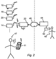
- the alarm system comprising a second category remote control device 11, a first perimeter alarm detector 16, a second perimeter alarm detector 18, an infrared detector 20 and a smoke detector 14 are operatively connected to a central monitoring station 44 through the gateway 22 and a network connection 46.
- a plurality of interconnected smoke detectors are provided. Interconnected smoke detectors will forward alarm signals to each other and thus improve the alarm signalling throughout the premises.
- the network connection 46 can be the internet, a wired telephone connection, a cellular telephone connection or any other suitable connection or combination of connections.
- the gateway 22 is provided with a self-contained power supply such as a battery so as to ensure communication and operation generally also during power failures.
- the second category remote control device 11 will change mode from sleeping mode to active mode when the panic button is pressed on the remote control device.
- a panic alarm signal will be transmitted to the gateway 22 and then further on to the central monitoring station 44.
- the central monitoring station initiates a voice communication between a supervisor 48 or other personnel and the user 47.
- a voice channel between the central monitoring station and the remote control device can be established also during other conditions and in either direction.
- the voice communication is a half-duplex communication system and communication will be possible in both directions, but only in one direction at a time. While the supervisor 48 is talking the communication system will transfer voice signals from the central monitoring station 44 to the second category remote control device 11. Sound signals will be emitted through the loudspeaker 42. In the shown embodiment the transfer of voice signals will go through the gateway 22. In other embodiments there will be a direct connection between the remote control device and the central monitoring station for the voice communication. An audio unit 50 at the central monitoring station 44 is used by the supervisor.
- the user is invited to talk and to transfer voice information in the reverse direction when the talk symbol of the remote control device is switched on. Normally, the supervisor or the central monitoring station will control the direction of communication switch on the talk symbol. Voice signals from the user are captured by the microphone 43.
- a basic configuration of the second category remote control device 11 is shown in Fig. 3 .
- a central processing unit 52 is connected to an input unit 54 and an output unit 56.
- the input unit 54 is connected to the arming button 36, the disarming button 38 and the panic button.
- the input unit 54 also is connected to and receives voice signals from the microphone 43.
- the central processing unit 52 is arranged also to code and to decode voice signals during voice communication.
- An output unit 56 is connected to the central processing unit 52 and also to the display 24 and to the display symbols 26.
- the output unit 56 also is connected to the talk symbol 32 and the loudspeaker 43.
- the output unit 56 receives decoded voice signals from the central processing unit 52 or a separate voice handling unit (not shown).
- the communications unit 58 comprises circuits and electronic devices that are suitable for radio communication at available frequencies, including circuits for coding/decoding, encryption/decryption, power adjustments.
- the communications unit 58 together with the central processing unit 52 are arranged to handle an authentication process between the wireless units, so as to ensure that wireless units not belonging to the alarm system interfere in or endanger the function of the alarm system.
- a motion detector 60 is connected to the central processing unit 52 to give an alert signal when predetermined levels of motion of the remote control device are detected.
- the motion detector comprises an accelerometer that can be based on different physical properties.
- the accelerometer can include a solid state detector utilizing a piezoelectric effect, changes in capacitance, piezoresistive effect and inertially responsive spring-mass systems.
- a first level of motions where the acceleration corresponds to lifting or tilting the second category remote control device 11 sets the remote control device into the active mode to energize backlight and other display functions. Arming of a selected group of alarm detectors is now possible.
- a second level of motions corresponds to dropping the remote control device or the acceleration that will be detected when a person carrying the remote control device falls. In various embodiments detection of the second level of motions results in transmitting a panic message to the central monitoring station and opening of the voice communication.
- the central processing unit 52 comprises a clock circuit (not shown) that is used for timing purposes, such as determining time intervals between radio communications with the gateway when the remote control device is in the sleeping mode.
- a general power supply unit 62 is connected to all unit power consuming units of the second category remote control device 11.
- the general power supply unit 62 comprises a battery. As long as the remote control device is in the sleeping mode the total power consumption of the remote control device is very low and also standard batteries will last for at least one year and preferably at least three years at normal use.
- An optional power supply 63 can be provided for the lamp 40. In accordance with such an embodiment the useful life of the general power supply will be more predictable.
- the optional power supply 63 can be a battery that is readily available through a cover of a housing of the remote control device.
Landscapes
- Physics & Mathematics (AREA)
- General Physics & Mathematics (AREA)
- Alarm Systems (AREA)
- Selective Calling Equipment (AREA)
Description
- The invention relates to a method and a device for arming and disarming alarm systems. Alarm systems comprising detectors and gateways are commonly used in private houses and office premises. Alarm detectors more and more frequently are connected through wireless communication means to a base unit or gateway which in turn is connected to a central monitoring station. In case of an alarm situation the alarm detector transmits an alarm signal to the gateway and the gateway transmits an alarm signal to the central monitoring station, should the alarm system be in an armed state.
- Besides being connected to the detectors the base station is provided with input means for receiving commands from a user. In various systems the base station is capable of receiving activation and deactivation, or arming and disarming, signals from remote control devices.
- Prior art remote control devices exist in different forms. A first embodiment of a remote control device comprises a wireless communication unit and a simple switch used for sending an arming signal and a disarming signal, respectively, to the base station. Other devices include an RFID (Radio Frequency IDentification) which has the advantage that no battery or other power source needs to be included in the device. Normally, a more sophisticated second embodiment of a remote control device is intended to be present within a protected area. The second embodiment of the remote control devices can be wall mounted in the vicinity of a door opening and requires some authorization steps before disarming is allowed.
- The use of different remote control devices for different purposes may lead to undesired situations where the system can be disarmed by unauthorized persons, should a remote control device be left unattended unintentionally.
- An example of arming and disarming an alarm system is known from
US 5 461 372 . - Battery powered devices suffer from a general disadvantage related to battery drain. Different measures have been suggested to lower the power consumption of such devices. Among such measures can be mentioned more efficient radio communication means and other low power electronic circuits. More sophisticated remote control devices are less frequently used since low power failures are considered more risky in alarm systems.
- The invention is defined in independent claims 1 and 7. An object of the present invention is to avoid the drawbacks set out above and to provide an improved method of arming and disarming an alarm system with the use of remote control devices. The improvements mainly are related to the disarming function. The remote control devices are connected over a wireless link to a gateway, also referred to as a control panel or base station. Further advantageous features and improvements are described below.
- In accordance with the invention at least two categories of remote control devices are used. A first category can be used unreservedly for both arming and disarming the alarm system. A second category is restricted from specific disarming functions.
- The alarm system can be armed in different ways and into different alarm system states, such as "Disarmed", "Armed Home" and "Armed Away". If the system is set to "Disarmed" it will not alarm to perimeter or interior detectors. Still, fire detectors, other gas detectors, flooding events, power break down events and similar detectors normally will be armed also in the "Disarmed" state. If the alarm system is set to a first armed state referred to as "Armed Home" the alarm system will generate an alarm at the occurrence of a breach of a first group of selected detectors such as perimeter detectors and selected interior detectors, but not to a breach of the interior detectors in general. If the system is set to a second armed state referred to as "Armed Away" it will alarm to a breach of the perimeter or interior detectors and normally to all types of detectors.
- The state of the system is determined by the needs of the occupants of the premises. If all of the occupants are leaving the premises then the alarm system should be set to "Armed Away". If the occupants will be staying within the premises for an extended period of time then the alarm system can be set to "Armed Home". This alarm setting can be appropriate for instance when the occupants are sleeping within the premises or are staying within a defined part thereof. For other scenarios the alarm system should be set to "Disarmed".
- In the "Armed Home" state a selected group of detectors is armed. In various embodiments the selected group of detectors includes the perimeter detectors and interior detectors covering sections of the premises that are not used by the occupants. Each installation can be set up with different detectors included in the selected group.
- A first category of remote control devices can be used for arming the system into either the "Armed Home" state or the "Armed Away" state. These devices also are allowed to disarm the system into the "Disarmed" state irrespective of the present armed state. Normally, remote control devices of the first category either are small portable units that can be carried together with keys in the pocket of a user, or wall mounted units arranged in the vicinity of door openings.
- The small portable device normally does not require any code, identification or authentication, neither for arming nor for disarming the system. It is intended to be carried by the user and not left available for unauthorized persons. To use the wall mounted units however, the user is required to provide some kind of authorization, code or authentication, at least for disarming the system. If this requirement can not be complied with no disarming function is allowed.
- A second category of remote control devices is used for arming the system into the "Armed Home" state and for disarming the system from "Armed Home" to "Disarmed". These devices are disabled from disarming the system from "Armed Away". As a result the second category of remote control devices can be left unattended when a user has armed the system into the "Armed Away" state. Even if an unauthorised person would come into possession of the remote control device the system could not be disarmed. According to the present invention devices in the second category are disabled permanently from disarming from "Armed Away", so as not to be capable of changing properties even if it is found and tampered with by an unauthorized person.
- Preferably, the second category of remote control devices also is limited to arming the system into the "Armed Home" state only. In various embodiments the limitation is fixed while in other embodiments it is possible to override the limitation by specific measures, for instance by pressing keys or buttons in a predetermined sequence.
- In various embodiments of the invention a specifically designed remote control device is included in the second category of remote control devices. The specifically designed remote control device is disabled from disarming the alarm system from "Armed Away". As a result the specifically designed remote control device can be left within a protected or not protected area because an intruder will not be able to disarm the alarm system from "Armed Away".
- Various embodiments of a remote control device in accordance with the invention are operable in two different modes. In a first sleeping mode only a minor part of electronic components and other means are active. In the sleeping mode the power consumption is very low resulting in an extending life time of batteries. In a second and active mode display means and communication means included in the remote control device are activated and all relevant functions are available.
- In accordance with one aspect of the invention the mode of operation is changed when motion of the remote control device is detected and optionally when the gateway transmits selected alarm signals. After detecting such motion the remote control device will enter the active mode. When the display means is activated different types of information previously received and stored in the remote control device are displayed to the user. This information may include that a detector included in the alarm system has detected fire, that a door or a window has been opened or any other desired condition.
- In the active mode it is further possible also to arm and disarm the alarm system as set out below and to carry out voice information exchange with a central monitoring station. In the sleeping mode there still is a sporadic radio communication with the gateway so as to allow registration and indication of alarm conditions. The remote control device also may send an acknowledge signal to the gateway so as to confirm that it is operable.
- In various embodiments the remote control device is arranged to arm and disarm the alarm system only at selected levels, such as perimeter protection. By arming the alarm system an internal state of the gateway is changed to armed. In the armed state reporting of an alarm signal from alarm detectors results in forwarding of alarm information to the central monitoring station. An alarm also may result in the generation of an alarm sound and/or other local indication of the alarm. The present state of the gateway can be transferred to selected or all alarm detectors The remote control device preferably is designed to have a size and weight that will not encourage a user to bring it out of the premises.
- In case of an emergency situation or if other circumstances are fulfilled it is possible to establish a voice connection between the remote control device and the central monitoring station. In various embodiments the connection is established through the gateway. If the emergency situation arises at the location of the remote control device the user initiates the connection by using input means of the remote control device. In a simple embodiment the input means in this respect is an alarm button. Emergency situations and also other reasons allow the central monitoring station to initiate voice communication.
- An alarm signal also is transmitted to the central monitoring station to ensure that appropriate measures are taken. When the voice connection is established the user is able to inform personnel at the central monitoring station about the present situation and an output device will output voice information that is received from the central monitoring station. In a simple embodiment the output device comprises a loudspeaker.
- The remote control device is provided also with other forms of output means. In various embodiments a graphic display unit is included and also symbol elements. The symbol elements can be provided with backlighting means that are activated and lit when there is a transition from the sleeping mode to the active mode. In various embodiments the symbol elements may include symbols depicting fire, an open door and a locked door. The graphic display unit can also be provided with backlighting means.
- Besides an alarm button and/or other alarm activating means the input means in various embodiments include an arm and disarm button, or separate buttons for arming and disarming the alarm system, and a talk symbol indicating that voice communication is available.
- The detection of motion of the remote control device can be provided by any type of accelerometer, including those based on piezoelectric effect, changes in capacitance, piezoresistive effect and inertially responsive spring-mass systems. The term accelerometer is used herein for any device that will produce a signal responsive of tilting and/or moving the remote control device. In various embodiments the accelerometer is sensitive also to shock or freefall and capable of discriminating between a normal lift up of the device and a situation where the device is dropped or when a person carrying it is falling.
- In order that the manner in which the above recited and other advantages and objects of the invention are obtained will be readily understood, a more particular description of the invention briefly described above will be rendered by reference to specific embodiments thereof which are illustrated in the appended drawings.
- Understanding that these drawings depict only typical embodiments of the invention and are not therefore to be considered to be limiting of its scope, the invention will be described and explained with additional specificity and detail through the use of the accompanying drawings in which:
- Fig. 1
- is a schematic perspective view of an installation including one embodiment of a system in accordance with the invention,
- Fig. 2
- is a schematic block diagram of an installation including an embodiment of the invention as shown in
Fig. 1 and an associated central monitoring station, and - Fig. 3
- is a schematic block diagram of one embodiment of a remote control device in accordance with the invention.
- The installation shown in
Fig. 1 is arranged in a conventional manner in a room. A first category portableremote control device 10 is shown schematically as to be carried by a user. A second categoryremote control device 11 is shown schematically as suitable to be arranged on a table or similar device. The installation includes a plurality of wireless alarm detectors, including asmoke detector 14, a firstperimeter alarm detector 16, a secondperimeter alarm detector 18 and a firstinfrared detector 20 or similar photodetector. Alarm signals fromsmoke detector 14 and detectors for gas or water leakage normally result in an alarm state, irrespective of the alarm system being armed or not. - The first
infrared detector 20 is an interior detector. Alarm signals from the detectors are transmitted to a wireless control panel orgateway 22. Detectors and the gateway form an alarm system. When the alarm system is armed the gateway will transmit an alarm signal to a central monitoring station (not shown) and normally also generate a sound alarm when an alarm signal from a detector is received. Signals from thesmoke detector 14 typically always will cause forwarding of an alarm signal irrespective of the mode of the gateway and will cause a sounder to be activated. Arming of the system normally is requested using akeypad 23 arranged by thedoor 12. Normally inputting of a code such as a PIN code is required to arm and to disarm the alarm system. Thekeypad 23 is a fixedly mounted first category remote control device. - The
smoke detector 14 is mounted in the ceiling of the premises and theinfrared detector 18 is mounted on a wall. The firstperimeter alarm detector 16 is installed above adoor 12 to detect when the door is opened. A corresponding secondperimeter alarm detector 18 is installed by awindow 13. In the shown embodiment thekeypad 23 is arranged by thedoor 12. Thegateway 22 is mounted in a room separated from the entrance of the premises. In the shown embodiment a secondinfrared detector 21 is arranged to cover thegateway 22, so as to ensure that an intruder cannot tamper with thegateway 22 when the system is armed. The secondinfrared detector 21 is an interior detector. - Preferably alarm system is armed into the "Armed Away" state by the
keypad 23 only, or by the portable arming and disarmingremote control device 10. Different arming states can be selected by pressing an associated button in connection with entering the code if thekeypad 23 is used. Normally, the portable arming and disarmingremote control device 10 is a more basic unit which is used for arming the system into a predetermined state, such as the "Armed Away" state, and for disarming the system from said "Armed Away" state into the "Disarmed" state. In the embodiment shown inFig. 1 the first category portableremote control device 10 comprises afirst arming button 13 used for arming the system into the predetermined state and asecond disarming button 15 used for disarming the system into the "Disarmed" state. The first category portableremote control device 10 is designed to be carried in the pocket of a user, for instance in a key ring through a key ring hole 17. - The alarm system can be disarmed into a disarmed state from a first armed state, such as the "Armed Home" state, in which a selected group of alarm detectors have been armed and from a second armed state, such as the "Armed Away" state, in which an extended group alarm detectors comprising also alarm detectors that are not included in said selected group have been armed. The extended group alarm detectors can comprise all detectors of the alarm system.
- The second category
remote control device 11 is used for arming the system into the "Armed Home" state only and is intended to be used by the bed or otherwise in a more stationary way than other portable devices. If the alarm system has been armed to the state "Armed Away" the second categoryremote control device 11 cannot be used to disarm the system. Normally, smoke detectors and other similar alarm detectors are active and will produce alarms when triggered irrespective of the present state of the alarm system. - The second category
remote control device 11 has a size and thickness that makes it less suitable to be carried in a pocket. It is provided with adisplay 24 andfurther display symbols 26. Preferably the display symbols are indicators of higher priority, such as afire symbol 28 and anopen symbol 30 indicating that a door or window or other perimeter entrance has been or is opened. Thedisplay 24 can be used for indicating more detailed information or information of lower priority. In various embodiments the display is used to indicate whether the alarm system is in an armed or disarmed state. A further display symbol is atalk symbol 32 indicating that a voice connection to a central monitoring station is open. This function is further explained below. The display symbols may all or at least some of them be provided with backlight means, so as to be distinctively observable also without ambient light. - The second category
remote control device 11 is provided with a set of input means including a panic orassault button 34. By pressing thepanic button 34 an alarm signal is forwarded to the central monitoring station irrespective of the present state of the remote control device. The remote control device is further provided with anarming button 36 and adisarming button 38. In various embodiments thearming button 36 is combined with the disarmingbutton 38 in a single button and the function is toggled between arming and disarming. - When the second category
remote control device 11 is used for arming only one or a plurality of perimeter alarm detectors or another group of selected alarm detectors are armed. The alarm system will be armed to the "Armed Home" state. A group of selected alarm detectors may include one alarm detector only. By limiting the function of the remote control device as described it is ensured that the alarm system is not fully but partly armed when a user still is present in the premises. Furthermore, it is also ensured that an intruder will not be able to disarm the alarm from an "Armed Away" state even if the intruder gains access to the remote control device. - A
lamp 40 can be used in emergency situations and when the second categoryremote control device 11 is operated in the night-time. A switch (not shown) can be used to manually switch on the light. In various embodiments the lamp is switched on automatically in case of fire and other high priority alarm situations. A separate power source, such as a battery, is connected to the lamp when power consumption is especially considered. Alarm signals and other sounds are generated in aloudspeaker 42. Theloudspeaker 42 is used also during voice communication as described below. The remote control device is provided with amicrophone 43 for capturing voice signals when a user talks.Display 24,display symbols 26,fire symbol 28,open symbol 30 and the loudspeaker are all indicating means used to inform a user of present conditions and status. - The second category
remote control device 11 normally is placed in a horizontal position on a table such as a bedside table. When left in a stationary position for a predetermined and adjustable time period the remote control device enters a sleeping mode. All power consuming circuits and display units are switched off or put into a low power state to reduce the power consumption. Also when in the sleeping mode a wireless connection still is maintained with thegateway 22. The wireless connection during sleeping mode mainly is a short beacon signal to establish a confirmation that the second categoryremote control device 11 is operable. - In various embodiments a wireless connection is established during a short time period followed by a longer time period without any signalling. The short time period can have a duration of 4 ms while the longer time period can last for 2 seconds. During a previous phase, such as during installation, an accurate synchronization between the remote control device and the gateway is carried out. A similar synchronization can be carried out also between the gateway and the alarm detectors.
- Should an alarm signal be sent from an alarm sensor to the gateway and the alarm system is in armed state a wake up signal is sent from the gateway to the remote control device. After receiving the wake up signal the remote control device will enter the active mode and display information regarding the present alarm situation. The displaying of information can include switching on the backlight means corresponding to the appropriate alarm symbol. High priority alarms, such as fire alarms, normally also result in activation of a sound alarm. In various embodiments also the
lamp 40 will be switched on to facilitate movements in the premises. - The second category
remote control device 11 also will change from sleeping mode to active mode when motion of the remote control device is detected. A motion corresponding to a lower level of acceleration, such as when the remote control device is lifted or tilted, will force the remote control device into the active mode and switch on backlight and display unit. Amotion detector 60 is provided in the remote control device. - Status of alarm detectors and other information previously received from the gateway will be displayed during a predetermined time period. The
lamp 40 can be switched on manually if desired. When a predetermined and adjustable time period has expired without any alarms or movements of the remote control device the status is reset to sleeping mode to save power. - In the embodiment shown in
Fig. 2 the alarm system comprising a second categoryremote control device 11, a firstperimeter alarm detector 16, a secondperimeter alarm detector 18, aninfrared detector 20 and asmoke detector 14 are operatively connected to acentral monitoring station 44 through thegateway 22 and anetwork connection 46. In various embodiments a plurality of interconnected smoke detectors are provided. Interconnected smoke detectors will forward alarm signals to each other and thus improve the alarm signalling throughout the premises. Thenetwork connection 46 can be the internet, a wired telephone connection, a cellular telephone connection or any other suitable connection or combination of connections. Thegateway 22 is provided with a self-contained power supply such as a battery so as to ensure communication and operation generally also during power failures. - The second category
remote control device 11 will change mode from sleeping mode to active mode when the panic button is pressed on the remote control device. When the panic button is pressed by a user 47 a panic alarm signal will be transmitted to thegateway 22 and then further on to thecentral monitoring station 44. The central monitoring station initiates a voice communication between asupervisor 48 or other personnel and theuser 47. A voice channel between the central monitoring station and the remote control device can be established also during other conditions and in either direction. - In various embodiments the voice communication is a half-duplex communication system and communication will be possible in both directions, but only in one direction at a time. While the
supervisor 48 is talking the communication system will transfer voice signals from thecentral monitoring station 44 to the second categoryremote control device 11. Sound signals will be emitted through theloudspeaker 42. In the shown embodiment the transfer of voice signals will go through thegateway 22. In other embodiments there will be a direct connection between the remote control device and the central monitoring station for the voice communication. Anaudio unit 50 at thecentral monitoring station 44 is used by the supervisor. - The user is invited to talk and to transfer voice information in the reverse direction when the talk symbol of the remote control device is switched on. Normally, the supervisor or the central monitoring station will control the direction of communication switch on the talk symbol. Voice signals from the user are captured by the
microphone 43. - A basic configuration of the second category
remote control device 11 is shown inFig. 3 . Acentral processing unit 52 is connected to aninput unit 54 and anoutput unit 56. Theinput unit 54 is connected to thearming button 36, the disarmingbutton 38 and the panic button. In the shown embodiment theinput unit 54 also is connected to and receives voice signals from themicrophone 43. In various embodiments thecentral processing unit 52 is arranged also to code and to decode voice signals during voice communication. - An
output unit 56 is connected to thecentral processing unit 52 and also to thedisplay 24 and to thedisplay symbols 26. Theoutput unit 56 also is connected to thetalk symbol 32 and theloudspeaker 43. During voice communication theoutput unit 56 receives decoded voice signals from thecentral processing unit 52 or a separate voice handling unit (not shown). - All communication to and from the
gateway 22 is handled in awireless communications unit 58 connected to thecentral processing unit 52. In various embodiments thecommunications unit 58 comprises circuits and electronic devices that are suitable for radio communication at available frequencies, including circuits for coding/decoding, encryption/decryption, power adjustments. Thecommunications unit 58 together with thecentral processing unit 52 are arranged to handle an authentication process between the wireless units, so as to ensure that wireless units not belonging to the alarm system interfere in or endanger the function of the alarm system. - A
motion detector 60 is connected to thecentral processing unit 52 to give an alert signal when predetermined levels of motion of the remote control device are detected. In various embodiments the motion detector comprises an accelerometer that can be based on different physical properties. The accelerometer can include a solid state detector utilizing a piezoelectric effect, changes in capacitance, piezoresistive effect and inertially responsive spring-mass systems. - A first level of motions where the acceleration corresponds to lifting or tilting the second category
remote control device 11 sets the remote control device into the active mode to energize backlight and other display functions. Arming of a selected group of alarm detectors is now possible. A second level of motions corresponds to dropping the remote control device or the acceleration that will be detected when a person carrying the remote control device falls. In various embodiments detection of the second level of motions results in transmitting a panic message to the central monitoring station and opening of the voice communication. - The
central processing unit 52 comprises a clock circuit (not shown) that is used for timing purposes, such as determining time intervals between radio communications with the gateway when the remote control device is in the sleeping mode. A generalpower supply unit 62 is connected to all unit power consuming units of the second categoryremote control device 11. In various embodiments the generalpower supply unit 62 comprises a battery. As long as the remote control device is in the sleeping mode the total power consumption of the remote control device is very low and also standard batteries will last for at least one year and preferably at least three years at normal use. - An
optional power supply 63 can be provided for thelamp 40. In accordance with such an embodiment the useful life of the general power supply will be more predictable. Theoptional power supply 63 can be a battery that is readily available through a cover of a housing of the remote control device. - While certain illustrative embodiments of the invention have been described in particularity, it will be understood that various other modifications will be readily apparent to those skilled in the art without departing from the scope of the invention as defined in the appended claims.
Claims (16)
- A method of disarming an alarm system into a disarmed state from a first armed state in which a selected group of alarm detectors have been armed and from a second armed state in which an extended group of alarm detectors comprising also alarm detectors that are not included in said selected group have been armed, characterised by the steps of enabling a first category of remote control devices (10; 23) for arming the alarm system into the first armed state and into the second armed state, enabling said first category of remote control devices (10; 23) for disarming the alarm system from the first armed state and from the second armed state,
enabling a second category (11) of remote control devices for arming the alarm system into the first armed state,
enabling said second category of remote control devices (11) for disarming the alarm system from the first armed state, and
disabling said second category of remote control devices (11) for disarming the alarm system from the second armed state. - A method as claimed in claim 1, where information is exchanged through a wireless communication link, comprising the steps of
sending activation instructions to at least one alarm detector and receiving and displaying data relating to status of at least said alarm detector in a wireless remote control device (11) included in said second category of remote control devices,
detecting motion of said wireless remote control device,
enabling the displaying of data after detecting the motion of the wireless remote control device, and
enabling sending of instructions for disarming a selected group of alarm detectors after detecting the motion of the wireless remote control device. - A method as claimed in claim 1 or 2, also including the steps of determining acceleration of the wireless remote control device (11) and generating an alarm signal when a determined value of acceleration exceeds a predetermined value.
- A method as claimed in claim 1 or 2, also including the step of activating backlight of display symbols (26) arranged on the wireless remote control device (11) when motion of said remote control device is detected.
- A method as claimed in claim 1, also including the steps of receiving a control signal allowing reception of voice signals and transmitting radio signals carrying information corresponding to said voice signals.
- A method as claimed in claim 1, also including the steps of receiving alarm signals generated in alarm detectors and activating associated indicating means arranged on the wireless remote control device (11) when an alarm signal is received.
- An alarm system capable of entering a first armed state in which a selected group of alarm detectors have been armed and a second armed state in which an extended group of alarm detectors comprising also alarm detectors that are not included in said selected group have been armed, said alarm system comprising at least two alarm detectors (14; 16; 18; 20) and a gateway (22), characterised by
a first category of remote control devices (10; 23) capable of arming the alarm system into the first armed state and into the second armed state, and of disarming the alarm system from the first armed state and from the second armed state, and
a second category of remote control devices (11) capable of arming the alarm system into the first armed state, and of disarming the alarm system from the first armed state, and wherein said second category of remote control devices (11) is disabled from disarming the alarm system from the second armed state. - An alarm system as claimed in claim 7, wherein said second category of remote control devices (11) comprises wireless communication means (58), display means (24; 26), input means (34; 36, 38), motion detection means (60) operatively connected to said display means for displaying information received from the at least one detector (14; 16; 18; 20) when motion is detected,
arming input means (36) for receiving arming instructions, wherein said arming input means (36) is operatively connected to said wireless communication means (58) and wherein said gateway (22) is set to a partly armed state upon receipt of an arming instructions forwarded by said wireless communication means (58), said gateway (22) in the partly armed state being arranged to generate an alarm signal upon receiving alarm signals from a selected group of detectors, and
disarming input means (38) for receiving disarming instructions, wherein said disarming input means (38) is operatively connected to said wireless communication means (58) and wherein said gateway (22) is set to a disarmed state from said partly armed state only upon receipt of an disarming instructions forwarded by said wireless communication means (58). - An alarm system as claimed in claim 7, wherein the remote control device (11) of the second category is provided with a plurality of display symbols (26) and associated backlight means.
- An alarm system as claimed in claim 8, wherein the motion detection means (60) is arranged to detect a first level of acceleration corresponding to lifting or tilting the remote control device (11) of the second category, and a second level of acceleration corresponding to dropping the remote control device of the second category.
- An alarm system as claimed in claim 8, wherein the remote control device (11) of the second category is provided with a loudspeaker (42) and a microphone (43) operatively connected to a communication unit (58) providing voice communication between the remote control device (11) of the second category and the gateway (22).
- An alarm system as claimed in claim 11, wherein said wireless communication means (58) comprises a half-duplex communication means arranged to allow a one way voice communication between the remote control device (11) of the second category and the gateway (22).
- An alarm system as claimed in claim 11 or claim 12, wherein the remote control device (11) of the second category is provided with a talk symbol (32) that is activated when voice communication in the direction from the remote control device (11) of the second category to the gateway (22) is allowed.
- A system as claimed in claim 8, wherein the selected group of alarm detectors consists of perimeter alarm detectors (16; 18).
- A system as claimed in claim 7, wherein the remote control device (11) of the second category is provided with a lamp (40) and wherein the motion detection means (60) is operatively connected to said lamp, so as to activate the lamp when motion is detected.
- A system as claimed in claim 15, wherein the remote control device (11) of the second category is provided with a separate power supply (63) supplying power to the lamp (40).
Priority Applications (2)
| Application Number | Priority Date | Filing Date | Title |
|---|---|---|---|
| ES10164171.0T ES2594760T3 (en) | 2010-05-27 | 2010-05-27 | Method and system for arming and disarming |
| EP10164171.0A EP2390854B1 (en) | 2010-05-27 | 2010-05-27 | A method and a system for arming and disarming |
Applications Claiming Priority (1)
| Application Number | Priority Date | Filing Date | Title |
|---|---|---|---|
| EP10164171.0A EP2390854B1 (en) | 2010-05-27 | 2010-05-27 | A method and a system for arming and disarming |
Publications (2)
| Publication Number | Publication Date |
|---|---|
| EP2390854A1 EP2390854A1 (en) | 2011-11-30 |
| EP2390854B1 true EP2390854B1 (en) | 2016-07-06 |
Family
ID=42988332
Family Applications (1)
| Application Number | Title | Priority Date | Filing Date |
|---|---|---|---|
| EP10164171.0A Active EP2390854B1 (en) | 2010-05-27 | 2010-05-27 | A method and a system for arming and disarming |
Country Status (2)
| Country | Link |
|---|---|
| EP (1) | EP2390854B1 (en) |
| ES (1) | ES2594760T3 (en) |
Family Cites Families (1)
| Publication number | Priority date | Publication date | Assignee | Title |
|---|---|---|---|---|
| US5461372A (en) * | 1993-01-19 | 1995-10-24 | Honeywell Inc. | System and method for modifying security in a security system |
-
2010
- 2010-05-27 ES ES10164171.0T patent/ES2594760T3/en active Active
- 2010-05-27 EP EP10164171.0A patent/EP2390854B1/en active Active
Also Published As
| Publication number | Publication date |
|---|---|
| EP2390854A1 (en) | 2011-11-30 |
| ES2594760T3 (en) | 2016-12-22 |
Similar Documents
| Publication | Publication Date | Title |
|---|---|---|
| US20110140868A1 (en) | Method and a system for exchanging information | |
| US10134265B2 (en) | Portable alarm system with self-monitoring sensor | |
| JP2004362252A (en) | Machine security system, control device, remote alarm, control method, control program, and computer-readable recording medium recording control program | |
| EP3989195B1 (en) | System and method for automatically disarming an intrusion detection system | |
| AU2024202157A1 (en) | A security monitoring system | |
| KR20130097258A (en) | Unmanned guard system | |
| EP2323113A1 (en) | A method and a system for exchanging information | |
| EP2390854A1 (en) | A method and a system for arming and disarming | |
| AU2020360874B2 (en) | A security monitoring system | |
| KR100742754B1 (en) | Unattended detection security system and its operation method | |
| JP2009265928A (en) | Security system | |
| EP4092643B1 (en) | A security monitoring system | |
| JP2009080585A (en) | Crime prevention system | |
| KR20230144430A (en) | Unmanned guard system | |
| CA2353870A1 (en) | Bi-directional wireless detection system | |
| KR100807814B1 (en) | Cooperation security system | |
| JP2005216051A (en) | Monitoring system and program thereof |
Legal Events
| Date | Code | Title | Description |
|---|---|---|---|
| AK | Designated contracting states |
Kind code of ref document: A1 Designated state(s): AL AT BE BG CH CY CZ DE DK EE ES FI FR GB GR HR HU IE IS IT LI LT LU LV MC MK MT NL NO PL PT RO SE SI SK SM TR |
|
| AX | Request for extension of the european patent |
Extension state: BA ME RS |
|
| PUAI | Public reference made under article 153(3) epc to a published international application that has entered the european phase |
Free format text: ORIGINAL CODE: 0009012 |
|
| 111Z | Information provided on other rights and legal means of execution |
Free format text: AL AT BE BG CH CY CZ DE DK EE ES FI FR GB GR HR HU IE IS IT LT LU LV MC MK MT NL NO PL PT RO SE SI SK SM TR Effective date: 20111027 |
|
| 17P | Request for examination filed |
Effective date: 20120530 |
|
| 17Q | First examination report despatched |
Effective date: 20120906 |
|
| GRAP | Despatch of communication of intention to grant a patent |
Free format text: ORIGINAL CODE: EPIDOSNIGR1 |
|
| INTG | Intention to grant announced |
Effective date: 20160104 |
|
| RIN1 | Information on inventor provided before grant (corrected) |
Inventor name: HOVANG, DAN |
|
| D11X | Information provided on other rights and legal means of execution (deleted) | ||
| 111Z | Information provided on other rights and legal means of execution |
Free format text: AL AT BE BG CH CY CZ DE DK EE ES FI FR GB GR HR HU IE IS IT LT LU LV MC MK MT NL NO PL PT RO SE SI SK SM TR Effective date: 20160114 |
|
| GRAS | Grant fee paid |
Free format text: ORIGINAL CODE: EPIDOSNIGR3 |
|
| GRAA | (expected) grant |
Free format text: ORIGINAL CODE: 0009210 |
|
| AK | Designated contracting states |
Kind code of ref document: B1 Designated state(s): AL AT BE BG CH CY CZ DE DK EE ES FI FR GB GR HR HU IE IS IT LI LT LU LV MC MK MT NL NO PL PT RO SE SI SK SM TR |
|
| REG | Reference to a national code |
Ref country code: GB Ref legal event code: FG4D |
|
| REG | Reference to a national code |
Ref country code: AT Ref legal event code: REF Ref document number: 811195 Country of ref document: AT Kind code of ref document: T Effective date: 20160715 Ref country code: CH Ref legal event code: EP |
|
| REG | Reference to a national code |
Ref country code: IE Ref legal event code: FG4D |
|
| REG | Reference to a national code |
Ref country code: DE Ref legal event code: R096 Ref document number: 602010034428 Country of ref document: DE |
|
| REG | Reference to a national code |
Ref country code: SE Ref legal event code: TRGR |
|
| REG | Reference to a national code |
Ref country code: NL Ref legal event code: MP Effective date: 20160706 |
|
| REG | Reference to a national code |
Ref country code: LT Ref legal event code: MG4D |
|
| REG | Reference to a national code |
Ref country code: AT Ref legal event code: MK05 Ref document number: 811195 Country of ref document: AT Kind code of ref document: T Effective date: 20160706 |
|
| REG | Reference to a national code |
Ref country code: ES Ref legal event code: FG2A Ref document number: 2594760 Country of ref document: ES Kind code of ref document: T3 Effective date: 20161222 |
|
| PG25 | Lapsed in a contracting state [announced via postgrant information from national office to epo] |
Ref country code: LT Free format text: LAPSE BECAUSE OF FAILURE TO SUBMIT A TRANSLATION OF THE DESCRIPTION OR TO PAY THE FEE WITHIN THE PRESCRIBED TIME-LIMIT Effective date: 20160706 Ref country code: NL Free format text: LAPSE BECAUSE OF FAILURE TO SUBMIT A TRANSLATION OF THE DESCRIPTION OR TO PAY THE FEE WITHIN THE PRESCRIBED TIME-LIMIT Effective date: 20160706 Ref country code: IS Free format text: LAPSE BECAUSE OF FAILURE TO SUBMIT A TRANSLATION OF THE DESCRIPTION OR TO PAY THE FEE WITHIN THE PRESCRIBED TIME-LIMIT Effective date: 20161106 Ref country code: HR Free format text: LAPSE BECAUSE OF FAILURE TO SUBMIT A TRANSLATION OF THE DESCRIPTION OR TO PAY THE FEE WITHIN THE PRESCRIBED TIME-LIMIT Effective date: 20160706 Ref country code: FI Free format text: LAPSE BECAUSE OF FAILURE TO SUBMIT A TRANSLATION OF THE DESCRIPTION OR TO PAY THE FEE WITHIN THE PRESCRIBED TIME-LIMIT Effective date: 20160706 Ref country code: NO Free format text: LAPSE BECAUSE OF FAILURE TO SUBMIT A TRANSLATION OF THE DESCRIPTION OR TO PAY THE FEE WITHIN THE PRESCRIBED TIME-LIMIT Effective date: 20161006 |
|
| PG25 | Lapsed in a contracting state [announced via postgrant information from national office to epo] |
Ref country code: GR Free format text: LAPSE BECAUSE OF FAILURE TO SUBMIT A TRANSLATION OF THE DESCRIPTION OR TO PAY THE FEE WITHIN THE PRESCRIBED TIME-LIMIT Effective date: 20161007 Ref country code: LV Free format text: LAPSE BECAUSE OF FAILURE TO SUBMIT A TRANSLATION OF THE DESCRIPTION OR TO PAY THE FEE WITHIN THE PRESCRIBED TIME-LIMIT Effective date: 20160706 Ref country code: AT Free format text: LAPSE BECAUSE OF FAILURE TO SUBMIT A TRANSLATION OF THE DESCRIPTION OR TO PAY THE FEE WITHIN THE PRESCRIBED TIME-LIMIT Effective date: 20160706 Ref country code: PL Free format text: LAPSE BECAUSE OF FAILURE TO SUBMIT A TRANSLATION OF THE DESCRIPTION OR TO PAY THE FEE WITHIN THE PRESCRIBED TIME-LIMIT Effective date: 20160706 Ref country code: PT Free format text: LAPSE BECAUSE OF FAILURE TO SUBMIT A TRANSLATION OF THE DESCRIPTION OR TO PAY THE FEE WITHIN THE PRESCRIBED TIME-LIMIT Effective date: 20161107 |
|
| REG | Reference to a national code |
Ref country code: DE Ref legal event code: R097 Ref document number: 602010034428 Country of ref document: DE |
|
| REG | Reference to a national code |
Ref country code: FR Ref legal event code: PLFP Year of fee payment: 8 |
|
| PG25 | Lapsed in a contracting state [announced via postgrant information from national office to epo] |
Ref country code: EE Free format text: LAPSE BECAUSE OF FAILURE TO SUBMIT A TRANSLATION OF THE DESCRIPTION OR TO PAY THE FEE WITHIN THE PRESCRIBED TIME-LIMIT Effective date: 20160706 Ref country code: RO Free format text: LAPSE BECAUSE OF FAILURE TO SUBMIT A TRANSLATION OF THE DESCRIPTION OR TO PAY THE FEE WITHIN THE PRESCRIBED TIME-LIMIT Effective date: 20160706 |
|
| PLBE | No opposition filed within time limit |
Free format text: ORIGINAL CODE: 0009261 |
|
| STAA | Information on the status of an ep patent application or granted ep patent |
Free format text: STATUS: NO OPPOSITION FILED WITHIN TIME LIMIT |
|
| PG25 | Lapsed in a contracting state [announced via postgrant information from national office to epo] |
Ref country code: SM Free format text: LAPSE BECAUSE OF FAILURE TO SUBMIT A TRANSLATION OF THE DESCRIPTION OR TO PAY THE FEE WITHIN THE PRESCRIBED TIME-LIMIT Effective date: 20160706 Ref country code: SK Free format text: LAPSE BECAUSE OF FAILURE TO SUBMIT A TRANSLATION OF THE DESCRIPTION OR TO PAY THE FEE WITHIN THE PRESCRIBED TIME-LIMIT Effective date: 20160706 Ref country code: DK Free format text: LAPSE BECAUSE OF FAILURE TO SUBMIT A TRANSLATION OF THE DESCRIPTION OR TO PAY THE FEE WITHIN THE PRESCRIBED TIME-LIMIT Effective date: 20160706 Ref country code: BG Free format text: LAPSE BECAUSE OF FAILURE TO SUBMIT A TRANSLATION OF THE DESCRIPTION OR TO PAY THE FEE WITHIN THE PRESCRIBED TIME-LIMIT Effective date: 20161006 Ref country code: CZ Free format text: LAPSE BECAUSE OF FAILURE TO SUBMIT A TRANSLATION OF THE DESCRIPTION OR TO PAY THE FEE WITHIN THE PRESCRIBED TIME-LIMIT Effective date: 20160706 |
|
| 26N | No opposition filed |
Effective date: 20170407 |
|
| REG | Reference to a national code |
Ref country code: DE Ref legal event code: R081 Ref document number: 602010034428 Country of ref document: DE Owner name: VERISURE SARL, CH Free format text: FORMER OWNER: SECURITAS DIRECT AB, MALMOE, SE |
|
| PG25 | Lapsed in a contracting state [announced via postgrant information from national office to epo] |
Ref country code: SI Free format text: LAPSE BECAUSE OF FAILURE TO SUBMIT A TRANSLATION OF THE DESCRIPTION OR TO PAY THE FEE WITHIN THE PRESCRIBED TIME-LIMIT Effective date: 20160706 Ref country code: LU Free format text: LAPSE BECAUSE OF NON-PAYMENT OF DUE FEES Effective date: 20170531 |
|
| REG | Reference to a national code |
Ref country code: GB Ref legal event code: 732E Free format text: REGISTERED BETWEEN 20170824 AND 20170830 |
|
| REG | Reference to a national code |
Ref country code: BE Ref legal event code: FP Effective date: 20161006 Ref country code: BE Ref legal event code: PD Owner name: VERISURE SARL; CH Free format text: DETAILS ASSIGNMENT: CHANGE OF OWNER(S), AFFECTATION / CESSION; FORMER OWNER NAME: SECURITAS DIRECT AB Effective date: 20170630 |
|
| REG | Reference to a national code |
Ref country code: FR Ref legal event code: CA Effective date: 20171109 Ref country code: FR Ref legal event code: TP Owner name: VERISURE SARL, CH Effective date: 20171109 |
|
| REG | Reference to a national code |
Ref country code: CH Ref legal event code: PL |
|
| REG | Reference to a national code |
Ref country code: ES Ref legal event code: PC2A Owner name: VERISURE SARL Effective date: 20180119 |
|
| PG25 | Lapsed in a contracting state [announced via postgrant information from national office to epo] |
Ref country code: MC Free format text: LAPSE BECAUSE OF FAILURE TO SUBMIT A TRANSLATION OF THE DESCRIPTION OR TO PAY THE FEE WITHIN THE PRESCRIBED TIME-LIMIT Effective date: 20160706 |
|
| REG | Reference to a national code |
Ref country code: IE Ref legal event code: MM4A |
|
| PG25 | Lapsed in a contracting state [announced via postgrant information from national office to epo] |
Ref country code: LI Free format text: LAPSE BECAUSE OF NON-PAYMENT OF DUE FEES Effective date: 20170531 Ref country code: CH Free format text: LAPSE BECAUSE OF NON-PAYMENT OF DUE FEES Effective date: 20170531 |
|
| PG25 | Lapsed in a contracting state [announced via postgrant information from national office to epo] |
Ref country code: LU Free format text: LAPSE BECAUSE OF NON-PAYMENT OF DUE FEES Effective date: 20170527 |
|
| PG25 | Lapsed in a contracting state [announced via postgrant information from national office to epo] |
Ref country code: IE Free format text: LAPSE BECAUSE OF NON-PAYMENT OF DUE FEES Effective date: 20170527 |
|
| REG | Reference to a national code |
Ref country code: FR Ref legal event code: PLFP Year of fee payment: 9 |
|
| PG25 | Lapsed in a contracting state [announced via postgrant information from national office to epo] |
Ref country code: MT Free format text: LAPSE BECAUSE OF NON-PAYMENT OF DUE FEES Effective date: 20170527 |
|
| PG25 | Lapsed in a contracting state [announced via postgrant information from national office to epo] |
Ref country code: AL Free format text: LAPSE BECAUSE OF FAILURE TO SUBMIT A TRANSLATION OF THE DESCRIPTION OR TO PAY THE FEE WITHIN THE PRESCRIBED TIME-LIMIT Effective date: 20160706 |
|
| PG25 | Lapsed in a contracting state [announced via postgrant information from national office to epo] |
Ref country code: HU Free format text: LAPSE BECAUSE OF FAILURE TO SUBMIT A TRANSLATION OF THE DESCRIPTION OR TO PAY THE FEE WITHIN THE PRESCRIBED TIME-LIMIT; INVALID AB INITIO Effective date: 20100527 |
|
| PG25 | Lapsed in a contracting state [announced via postgrant information from national office to epo] |
Ref country code: CY Free format text: LAPSE BECAUSE OF NON-PAYMENT OF DUE FEES Effective date: 20160706 |
|
| PG25 | Lapsed in a contracting state [announced via postgrant information from national office to epo] |
Ref country code: MK Free format text: LAPSE BECAUSE OF FAILURE TO SUBMIT A TRANSLATION OF THE DESCRIPTION OR TO PAY THE FEE WITHIN THE PRESCRIBED TIME-LIMIT Effective date: 20160706 |
|
| PG25 | Lapsed in a contracting state [announced via postgrant information from national office to epo] |
Ref country code: TR Free format text: LAPSE BECAUSE OF FAILURE TO SUBMIT A TRANSLATION OF THE DESCRIPTION OR TO PAY THE FEE WITHIN THE PRESCRIBED TIME-LIMIT Effective date: 20160706 |
|
| PGFP | Annual fee paid to national office [announced via postgrant information from national office to epo] |
Ref country code: DE Payment date: 20250529 Year of fee payment: 16 |
|
| PGFP | Annual fee paid to national office [announced via postgrant information from national office to epo] |
Ref country code: GB Payment date: 20250527 Year of fee payment: 16 Ref country code: ES Payment date: 20250602 Year of fee payment: 16 |
|
| PGFP | Annual fee paid to national office [announced via postgrant information from national office to epo] |
Ref country code: BE Payment date: 20250527 Year of fee payment: 16 Ref country code: IT Payment date: 20250521 Year of fee payment: 16 |
|
| PGFP | Annual fee paid to national office [announced via postgrant information from national office to epo] |
Ref country code: FR Payment date: 20250526 Year of fee payment: 16 |
|
| PGFP | Annual fee paid to national office [announced via postgrant information from national office to epo] |
Ref country code: SE Payment date: 20250527 Year of fee payment: 16 |