EP2390777A2 - Touch interface for three-dimensional display control - Google Patents
Touch interface for three-dimensional display control Download PDFInfo
- Publication number
- EP2390777A2 EP2390777A2 EP11167470A EP11167470A EP2390777A2 EP 2390777 A2 EP2390777 A2 EP 2390777A2 EP 11167470 A EP11167470 A EP 11167470A EP 11167470 A EP11167470 A EP 11167470A EP 2390777 A2 EP2390777 A2 EP 2390777A2
- Authority
- EP
- European Patent Office
- Prior art keywords
- display
- touch
- touch panel
- electronic device
- referred
- Prior art date
- Legal status (The legal status is an assumption and is not a legal conclusion. Google has not performed a legal analysis and makes no representation as to the accuracy of the status listed.)
- Withdrawn
Links
Images


Classifications
-
- G—PHYSICS
- G06—COMPUTING; CALCULATING OR COUNTING
- G06F—ELECTRIC DIGITAL DATA PROCESSING
- G06F3/00—Input arrangements for transferring data to be processed into a form capable of being handled by the computer; Output arrangements for transferring data from processing unit to output unit, e.g. interface arrangements
- G06F3/01—Input arrangements or combined input and output arrangements for interaction between user and computer
- G06F3/048—Interaction techniques based on graphical user interfaces [GUI]
- G06F3/0487—Interaction techniques based on graphical user interfaces [GUI] using specific features provided by the input device, e.g. functions controlled by the rotation of a mouse with dual sensing arrangements, or of the nature of the input device, e.g. tap gestures based on pressure sensed by a digitiser
- G06F3/0488—Interaction techniques based on graphical user interfaces [GUI] using specific features provided by the input device, e.g. functions controlled by the rotation of a mouse with dual sensing arrangements, or of the nature of the input device, e.g. tap gestures based on pressure sensed by a digitiser using a touch-screen or digitiser, e.g. input of commands through traced gestures
-
- G—PHYSICS
- G06—COMPUTING; CALCULATING OR COUNTING
- G06F—ELECTRIC DIGITAL DATA PROCESSING
- G06F1/00—Details not covered by groups G06F3/00 - G06F13/00 and G06F21/00
- G06F1/16—Constructional details or arrangements
- G06F1/1613—Constructional details or arrangements for portable computers
- G06F1/1633—Constructional details or arrangements of portable computers not specific to the type of enclosures covered by groups G06F1/1615 - G06F1/1626
- G06F1/1637—Details related to the display arrangement, including those related to the mounting of the display in the housing
- G06F1/1643—Details related to the display arrangement, including those related to the mounting of the display in the housing the display being associated to a digitizer, e.g. laptops that can be used as penpads
-
- G—PHYSICS
- G06—COMPUTING; CALCULATING OR COUNTING
- G06F—ELECTRIC DIGITAL DATA PROCESSING
- G06F1/00—Details not covered by groups G06F3/00 - G06F13/00 and G06F21/00
- G06F1/16—Constructional details or arrangements
- G06F1/1613—Constructional details or arrangements for portable computers
- G06F1/1633—Constructional details or arrangements of portable computers not specific to the type of enclosures covered by groups G06F1/1615 - G06F1/1626
- G06F1/1684—Constructional details or arrangements related to integrated I/O peripherals not covered by groups G06F1/1635 - G06F1/1675
- G06F1/169—Constructional details or arrangements related to integrated I/O peripherals not covered by groups G06F1/1635 - G06F1/1675 the I/O peripheral being an integrated pointing device, e.g. trackball in the palm rest area, mini-joystick integrated between keyboard keys, touch pads or touch stripes
-
- G—PHYSICS
- G06—COMPUTING; CALCULATING OR COUNTING
- G06F—ELECTRIC DIGITAL DATA PROCESSING
- G06F3/00—Input arrangements for transferring data to be processed into a form capable of being handled by the computer; Output arrangements for transferring data from processing unit to output unit, e.g. interface arrangements
- G06F3/01—Input arrangements or combined input and output arrangements for interaction between user and computer
- G06F3/03—Arrangements for converting the position or the displacement of a member into a coded form
- G06F3/033—Pointing devices displaced or positioned by the user, e.g. mice, trackballs, pens or joysticks; Accessories therefor
- G06F3/0338—Pointing devices displaced or positioned by the user, e.g. mice, trackballs, pens or joysticks; Accessories therefor with detection of limited linear or angular displacement of an operating part of the device from a neutral position, e.g. isotonic or isometric joysticks
-
- G—PHYSICS
- G06—COMPUTING; CALCULATING OR COUNTING
- G06F—ELECTRIC DIGITAL DATA PROCESSING
- G06F3/00—Input arrangements for transferring data to be processed into a form capable of being handled by the computer; Output arrangements for transferring data from processing unit to output unit, e.g. interface arrangements
- G06F3/01—Input arrangements or combined input and output arrangements for interaction between user and computer
- G06F3/03—Arrangements for converting the position or the displacement of a member into a coded form
- G06F3/033—Pointing devices displaced or positioned by the user, e.g. mice, trackballs, pens or joysticks; Accessories therefor
- G06F3/0354—Pointing devices displaced or positioned by the user, e.g. mice, trackballs, pens or joysticks; Accessories therefor with detection of 2D relative movements between the device, or an operating part thereof, and a plane or surface, e.g. 2D mice, trackballs, pens or pucks
- G06F3/03547—Touch pads, in which fingers can move on a surface
-
- G—PHYSICS
- G06—COMPUTING; CALCULATING OR COUNTING
- G06F—ELECTRIC DIGITAL DATA PROCESSING
- G06F3/00—Input arrangements for transferring data to be processed into a form capable of being handled by the computer; Output arrangements for transferring data from processing unit to output unit, e.g. interface arrangements
- G06F3/01—Input arrangements or combined input and output arrangements for interaction between user and computer
- G06F3/048—Interaction techniques based on graphical user interfaces [GUI]
- G06F3/0481—Interaction techniques based on graphical user interfaces [GUI] based on specific properties of the displayed interaction object or a metaphor-based environment, e.g. interaction with desktop elements like windows or icons, or assisted by a cursor's changing behaviour or appearance
- G06F3/04815—Interaction with a metaphor-based environment or interaction object displayed as three-dimensional, e.g. changing the user viewpoint with respect to the environment or object
-
- G—PHYSICS
- G06—COMPUTING; CALCULATING OR COUNTING
- G06F—ELECTRIC DIGITAL DATA PROCESSING
- G06F2203/00—Indexing scheme relating to G06F3/00 - G06F3/048
- G06F2203/048—Indexing scheme relating to G06F3/048
- G06F2203/04808—Several contacts: gestures triggering a specific function, e.g. scrolling, zooming, right-click, when the user establishes several contacts with the surface simultaneously; e.g. using several fingers or a combination of fingers and pen
Definitions
- a touch screen may act as an output device that displays image, video and/or graphical information, and which further may act as an input touch interface device for receiving touch control inputs from a user.
- a touch screen (or touch panel, or touch panel display) may detect the presence and location of a touch within the area of the display, where the touch may include a touching of the display with a body part (e.g., a finger) or with certain objects (e.g., a stylus).
- Touch screens typically enable the user to interact directly with what is being displayed, rather than indirectly with a cursor controlled by a mouse or touchpad. Touch screens have become widespread in use with various different types of consumer electronic devices, including, for example, cellular radiotelephones, personal digital assistants (PDAs), and hand-held gaming devices.
- PDAs personal digital assistants
- an electronic device may include a first touch panel disposed on a first side of the device and configured to receive a first touch input, and a display disposed on the first side of the device.
- the electronic device may further include a touch interface configured to receive a second touch input, wherein the touch interface is disposed on a second side of the device that is different than the first side of the device.
- the electronic device may also include a control unit configured to: receive an indication of the first touch input from the first touch panel, receive an indication of the second touch input from the touch interface, determine alterations to a three dimensional view of the display in the x, y and/or z directions based on the first touch input, and rotate the three dimensional view on the display angularly in accordance with movement of the second touch input.
- a control unit configured to: receive an indication of the first touch input from the first touch panel, receive an indication of the second touch input from the touch interface, determine alterations to a three dimensional view of the display in the x, y and/or z directions based on the first touch input, and rotate the three dimensional view on the display angularly in accordance with movement of the second touch input.
- control unit when rotating the three dimensional view on the display angularly in accordance with movement of the second touch input, the control unit may be further configured to adjust the three dimensional view within 360 degrees on the x and y axis in a direction corresponding to the second touch input.
- the electronic device may include a hand-held electronic device.
- the electronic device may include one of a cellular radiotelephone, a satellite navigation device, a smart phone, a Personal Communications System (PCS) terminal, a personal digital assistant (PDA), a gaming device, a media player device, a tablet computer, or a digital camera.
- a cellular radiotelephone a satellite navigation device
- a smart phone a personal Communications System (PCS) terminal
- a personal digital assistant (PDA) a gaming device
- media player device a media player device
- tablet computer or a digital camera.
- the first touch panel may include at least one of a near field-sensitive, an acoustically-sensitive, or a photo-sensitive touch panel.
- touch interface may include one of a joystick or a second touch panel.
- the second touch panel may include at least one of a near field-sensitive, an acoustically-sensitive, or a photo-sensitive touch panel.
- the display may include a liquid crystal display (LCD), a cathode ray tube (CRT) display, an organic light-emitting diode (OLED) display, a surface-conduction electro-emitter display (SED), a plasma display, a field emission display (FED), or a bistable display.
- LCD liquid crystal display
- CRT cathode ray tube
- OLED organic light-emitting diode
- SED surface-conduction electro-emitter display
- FED field emission display
- bistable display bistable display.
- the first touch panel may be integrated with, or overlaid upon, the display.
- a method may include receiving an indication of a first touch input on a first touch panel disposed on an electronic device, and receiving an indication of movement of a second touch input on a touch interface that is disposed on the electronic device separately from the first touch panel.
- the method may further include determining alterations to a three dimensional view of a display disposed on the electronic device in the x, y and/or z directions based on the indication of the first touch input, and rotating the three dimensional view on the display angularly in accordance with the movement of the second touch input.
- rotating the three dimensional view on the display may include adjusting the three dimensional view within 360 degrees on the x and y axis in a direction corresponding to the second touch input.
- the electronic device may include one of a cellular radiotelephone, a satellite navigation device, a smart phone; a Personal Communications System (PCS) terminal, a personal digital assistant (PDA), a gaming device, a media player device, a tablet computer, or a digital camera.
- a cellular radiotelephone a satellite navigation device
- a smart phone a personal Communications System (PCS) terminal
- PDA personal digital assistant
- gaming device a media player device
- tablet computer a tablet computer
- a digital camera a digital camera
- the first touch panel may include at least one of a near field-sensitive, an acoustically-sensitive, or a photo-sensitive touch panel.
- the touch interface may include one of a joystick or a second touch panel.
- the second touch panel may include at least one of a near field-sensitive, an acoustically-sensitive, or a photo-sensitive touch panel.
- the display may include a liquid crystal display (LCD), a cathode ray tube (CRT) display, an organic light-emitting diode (OLED) display, a surface-conduction electro-emitter display (SED), a plasma display, a field emission display (FED), or a bistable display.
- LCD liquid crystal display
- CRT cathode ray tube
- OLED organic light-emitting diode
- SED surface-conduction electro-emitter display
- FED field emission display
- bistable display bistable display.
- a hand-held electronic device may include a display and a first touch panel configured to receive a first touch input, wherein the first touch panel is integrated with, or overlaid upon, the display.
- the hand-held electronic device may further include a touch interface configured to receive a second touch input, wherein the touch interface is separate from the first touch panel and wherein the touch interface comprises a second touch panel or a joystick.
- the hand-held electronic device may also include a control unit configured to adjust a three dimensional view on the display based on the first touch input and the second touch input.
- the hand-held electronic device may include one of a cellular radiotelephone, a satellite navigation device, a smart phone, a Personal Communications System (PCS) terminal, a personal digital assistant (PDA), a gaming device, a media player device, or a digital camera and the display may include a liquid crystal display (LCD), a cathode ray tube (CRT) display, an organic light-emitting diode (OLED) display, a surface-conduction electro-emitter display (SED), a plasma display, a field emission display (FED), or a bistable display.
- LCD liquid crystal display
- CRT cathode ray tube
- OLED organic light-emitting diode
- SED surface-conduction electro-emitter display
- FED field emission display
- each of the first touch panel and the second touch panel may include at least one of a near field-sensitive, an acoustically-sensitive, or a photo-sensitive touch panel.
- the hand-held electronic device may include a front side and a rear side, and wherein the display and first touch panel are disposed on the front side and the touch interface is disposed on the rear side.
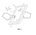
- FIG. 1 is a diagram that illustrates an overview of the use of an additional touch interface on an electronic device to permit more degrees of freedom in controlling graphics displayed on the device's display;
- FIGS. 2A and 2B are diagrams that depict two different exemplary embodiments of the electronic device of FIG. 1 ;
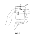
- FIG. 3 is a diagram that depicts a user using the electronic device of FIG. 1 to navigate within a view of the display of the electronic device of FIG. 1 using both a touch panel on a front of the device and a touch interface on the rear of the device;
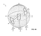
- FIG. 4A is a diagram that illustrates exemplary navigation within a three-dimensional view that may be displayed on the display of the electronic device of FIG. 1 ;
- FIG. 4B is a diagram that further illustrates the exemplary navigation within the three dimensional view of FIG. 4A in a two-dimensional representation
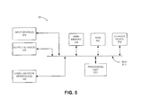
- FIG. 5 is a block diagram that depicts exemplary components of the electronic device of FIG. 1 ;
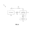
- FIG. 6 is a diagram that depicts an exemplary functional interaction between components of the electronic device of FIG. 1 ;
- FIG. 7 is a flow diagram illustrating an exemplary process for controlling navigation within a three dimensional view displayed on a display of the electronic device of FIG. 1 based on touch inputs applied to the touch panel and to the separate touch interface.
- FIG. 1 illustrates an overview of the use of an additional touch interface 110 on an electronic device 100 to permit more degrees of freedom in controlling graphics displayed on the device's display, such as, for example, more degrees of freedom in navigating in three dimensions (3-D) in graphics displayed on the device's display.
- electronic device 100 may include a touch panel 120, disposed on a front of device 100, that may display graphics and which may permit control of the device via touch input 130 by the device user.
- Electronic device 100 may further include additional touch interface 110, disposed on the back of device 100, to permit additional control of device 100 via additional touch input 140.
- touch or “touch input,” as used herein, may refer to a touch of an object, such as a body part (e.g., a finger) or a pointing device (e.g., a stylus, pen, etc.).
- Electronic device 100 may include any type of electronic device that includes a touch panel and display.
- device 100 may include a cellular radiotelephone; a satellite navigation device; a smart phone; a Personal Communications System (PCS) terminal that may combine a cellular radiotelephone with data processing, facsimile and data communications capabilities; a personal digital assistant (PDA) that can include a radiotelephone, pager, Internet/Intranet access, Web browser, organizer, calendar and/or a global positioning system (GPS) receiver; a gaming device; a media player device; a tablet computer; a digital camera; or another device that may use touch input.
- PDA personal digital assistant
- device 100 may include a hand-held electronic device.
- Touch panel 120 may be integrated with, and/or overlaid on, a display to form a touch screen or a panel-enabled display that may function as a user input interface.
- touch panel 120 may include a near field-sensitive (e.g., capacitive), acoustically-sensitive (e.g., surface acoustic wave), photo-sensitive (e.g., infrared), and/or any other type of touch panel that allows a display to be used as an input device.
- touch panel 120 may include multiple touch-sensitive technologies.
- touch panel 120 may include any kind of technology that provides the ability to identify the occurrence of a touch upon touch panel 120.
- the display associated with touch panel 120 may include a device that can display signals generated by device 100 as three dimensional text or images on a screen (e.g., a liquid crystal display (LCD), cathode ray tube (CRT) display, organic light-emitting diode (OLED) display, surface-conduction electro-emitter display (SED), plasma display, field emission display (FED), bistable display, etc.).
- the display may provide a high-resolution, active-matrix presentation suitable for the wide variety of applications and features associated with typical devices.
- the display may provide visual information to the user and serve—in conjunction with touch panel 120—as a user interface to detect user input.
- Touch interface 110 may include a touch panel (e.g., similar to touch panel 120, but having smaller dimensions), or a joystick (e.g., a micro-joystick designed for hand-held devices).
- touch input 130 to touch panel 120 may permit navigation within a three dimensional view on the display in x, y or z directions.
- Existing Pre-sense or force feedback techniques may be used to navigate in the z direction (i.e., navigate in depth "into" the displayed 3-D view) within the three dimensional view on the display of device 100. For example, applying pressure on touch panel 120 at a single point may cause navigation in the z direction in depth into the 3-D view displayed on device 100.
- touch input 140 to touch interface 110 may cause the displayed view to rotate angular to the movement of touch input 140 on touch interface 110.
- touch panel 120 in conjunction with touch interface 110, the user of device 100 may rotate and enter sideways into the 3-D view on the display of device 100.
- touch panel 120 on device 100 may be used to pan left, right, up, down, or in the z direction, while touch interface 110 may be used to adjust a heading in the 3-D view in 360 degrees on the x and y axes.
- Use of touch panel 120, in conjunction with touch interface 110 may, thus, permit the user to navigate sideways in depth in a 3-D view displayed on electronic device 100.
- touch panel 120 to navigate in the 3-D view is described in more detail below with respect to FIGS. 4A and 4B .
- FIGS. 2A and 2B depict two different exemplary embodiments of device 100 where, in one embodiment, device 100 implements a touch panel for touch interface 110 and, in another embodiment, device 100 implements a joystick for touch interface 110.
- front 200 of device 100 may include touch panel 120, a speaker 220 and a microphone 230.
- rear 210 of device 100 may include a camera 240 and touch interface 110 may include a touch panel.
- rear 210 of device 100 may include camera 240 and touch interface 110 may include a joystick.
- FIG. 3 depicts a user using device 100 to navigate within a view of the device 100's display using both a touch panel on a front of device 100 and a touch interface on the rear of device 100.
- the user may hold device 100 such that one finger (e.g., a thumb) may apply touch input 130 to touch panel 120 on a front of device 100, and another finger (e.g., an index finger) may apply touch input 140 to touch interface 110 on a rear of device 100.
- a thumb as shown in FIG. 3
- user may alternatively use an index finger of the user's other hand to apply touch input 130 to touch panel 120.
- FIG. 4A illustrates exemplary navigation within a three-dimensional representation of a 3-D view 400 that may be displayed on the display of device 100.
- FIG. 4B further illustrates the exemplary navigation within the 3-D view 400 of FIG. 4A in a two-dimensional representation.
- FIG. 4A depicts 360 degrees of a background that may be displayed on the display of device 100. The particular view of the background may be altered based on touch input to touch interface 110.
- an initial view A may correspond to joystick touch interface 110 being in a centered position 410.
- the user may then adjust joystick touch interface 110 to a position 420 such that the 3-D view rotates down and left to a second view B.
- the user may subsequently adjust joystick touch interface 110 to a position 430 such that the 3-D view rotates up and to the right to a third view C.
- the 3-D view 400 may be rotated angularly in 360 degrees in a direction that corresponds to the movement of joystick touch interface 110.
- use of joystick touch interface 110 on a rear of device 100 permits the 3-D view to be "entered" sideways thereby permitting an additional level of freedom during 3-D interface navigation.
- Navigation within the 3-D view 400 shown in FIG. 4A may, therefore, correspond to changes in the azimuthal angle ⁇ and the polar angle ⁇ within a spherical coordinate system (with the radius r being held constant).
- the azimuthal angle ⁇ is measured in the x-y plane from the x-axis with 0 ⁇ ⁇ ⁇ 2 ⁇ .
- the polar angle ⁇ is further measured from the positive z-axis with 0 ⁇ ⁇ ⁇ ⁇ , and the radius r is the distance from the origin of the coordinate system.
- 3-D view 400 may, thus, rotate up to 360 degrees around the spherical coordinate system in any direction (shown in FIG. 4A in the movement between A, B and C).
- FIG. 5 is a block diagram that depicts exemplary components of device 100.
- device 100 may include a bus 510, a processing unit 520, a main memory 530, a read only memory (ROM) 540, a storage device 550, an input device(s) 560, an output device(s) 570, and a communication interface(s) 580.
- Bus 510 may include a path that permits communication among the elements of device 100.
- Processing unit 520 may include a conventional processor, microprocessor, or processing logic that may interpret and execute instructions.
- Main memory 530 may include a random access memory (RAM) or another type of dynamic storage device that may store information and instructions for execution by processor 520.
- ROM 540 may include a conventional ROM device or another type of static storage device that may store static information and instructions for use by processing unit 520.
- Storage device 550 may include a magnetic and/or optical recording medium and its corresponding drive.
- Input device 560 may include a mechanism that permits a user to input information to device 100, such as a mouse, a pen, voice recognition and/or biometric mechanisms, etc. Input device 560 may further include touch panel 110 described above.
- Output device 570 may include a mechanism that outputs information to the operator, including a display, a printer, a speaker, etc.
- Communication interface 580 may include any transceiver-like mechanism that enables device 100 to communicate with other devices and/or systems.
- Device 100 may perform certain operations or processes described herein. Device 100 may perform these operations in response to processing unit 520 executing software instructions contained in a computer-readable medium, such as memory 530.
- a computer-readable medium may be defined as a physical or logical memory device.
- Each of main memory 530, ROM 540 and storage device 550 may include computer-readable media.
- the magnetic and/or optical recording media (e.g., readable CDs or DVDs) of storage device 550 may also include computer-readable media.
- the software instructions may be read into memory 530 from another computer-readable medium, such as data storage device 550, or from another device via communication interface 580.
- the software instructions contained in memory 530 may cause processing unit 520 to perform operations or processes described herein.
- hardwired circuitry may be used in place of or in combination with software instructions to implement processes described herein.
- implementations described herein are not limited to any specific combination of hardware circuitry and software.
- Device 100 may include additional, fewer, and/or different components or differently configured components than those depicted in FIG. 5 .
- FIG. 6 depicts an exemplary functional interaction between components of device 100.
- a 3-D view control unit 600 may receive indications of touch inputs 130 and 140 from touch panel 120 and touch interface 110, respectively.
- 3-D view control unit 600 may, for example, be implemented by processing unit 520.
- 3-D view control unit 600 may determine alterations to the view on the device 100's display in the x, y and/or z directions.
- 3-D view control unit 600 may rotate the 3-D view angularly along the x and y axes in correspondence with the movement of the touch input on touch interface 110.
- 3-D view control unit 600 may supply the generated 3-D view 610 to the display (not shown) for generating a 3-D view on the display.
- FIG. 7 is a flow diagram illustrating an exemplary process 700 for controlling navigation within a 3-D view displayed on a display of device 100 based on touch inputs applied to touch panel 120 and to the separate touch interface 110.
- the exemplary process of FIG. 7 may be performed by 3-D view control unit 600, possibly in conjunction with other components of device 100.
- the exemplary process may include receiving a first touch input from touch panel 120 on the front of device 100 (block 710).
- the user while holding device 100, may apply touch input 130 to touch panel 120 on front of device 100.
- 3-D view control unit 600 may further receive a second touch input from touch interface 110 on the rear of device 100 (block 720).
- the user while holding device 100, may apply touch input 140 to touch interface 110 on the rear of device 100.
- Alterations to the view on the display in the x, y and/or z directions may be determined based on the received first touch input (block 730).
- 3-D view control unit 600 may determine alterations to be applied to the view on the display of device 100 based on touch input 130 received from touch panel 120. For example, 3-D view control unit 600 may determine changes in the view on the display in the x and y direction (i.e., in the length and width directions of the display), and in the z direction (i.e., in depth into the display) that correspond to the user's touch input.
- the 3-D view may be rotated angularly in accordance with movement of the second touch input (block 740).
- 3-D view control unit 600 may rotate the view angularly up to 360 degrees in a direction that corresponds to the movement of touch input 140 on touch interface 110.
- the 3-D view correspondingly moves angularly along the spherical view from view A to view B.
- Rotating the 3-D view angularly may correspond to causing changes in the azimuthal angle ⁇ and the polar angle ⁇ if the view of the display of device 100 is modeled as a spherical coordinate system (coordinates in a spherical coordinate system being the azimuthal angle ⁇ , the polar angle ⁇ , and the radius r).
- Implementations described herein provide an additional touch interface that permits enhanced navigation in three dimensions on a display of an electronic device.
- a location of the additional touch interface on the rear of the electronic device in addition to having a touch panel and display on the front of the device, permits the user to use one finger to adjust the view on the display using the touch panel, and to use another finger to further adjust the view on the display using the touch interface on the rear of the device.
- touch inputs to the touch panel on the front of the device may adjust the view on the display in the x, y and/or z directions whereas touch inputs to the touch interface on the rear of the device may adjust the 3-D view angularly in the direction of movement of the touch input.
- By rotating the 3-D view angularly use of touch interface 110 on a rear of device 100 permits the 3-D view to be "entered" sideways, thereby, permitting an additional level of freedom during 3-D interface navigation.
- This logic or unit may include hardware, such as one or more processors, microprocessors, application specific integrated circuits, or field programmable gate arrays, software, or a combination of hardware and software.
Landscapes
- Engineering & Computer Science (AREA)
- Theoretical Computer Science (AREA)
- General Engineering & Computer Science (AREA)
- Human Computer Interaction (AREA)
- Physics & Mathematics (AREA)
- General Physics & Mathematics (AREA)
- Computer Hardware Design (AREA)
- Position Input By Displaying (AREA)
- User Interface Of Digital Computer (AREA)
- Controls And Circuits For Display Device (AREA)
Abstract
Description
- Many different types of consumer electronics devices nowadays typically include a touch screen that may act as an output device that displays image, video and/or graphical information, and which further may act as an input touch interface device for receiving touch control inputs from a user. A touch screen (or touch panel, or touch panel display) may detect the presence and location of a touch within the area of the display, where the touch may include a touching of the display with a body part (e.g., a finger) or with certain objects (e.g., a stylus). Touch screens typically enable the user to interact directly with what is being displayed, rather than indirectly with a cursor controlled by a mouse or touchpad. Touch screens have become widespread in use with various different types of consumer electronic devices, including, for example, cellular radiotelephones, personal digital assistants (PDAs), and hand-held gaming devices.
- In one exemplary embodiment, an electronic device may include a first touch panel disposed on a first side of the device and configured to receive a first touch input, and a display disposed on the first side of the device. The electronic device may further include a touch interface configured to receive a second touch input, wherein the touch interface is disposed on a second side of the device that is different than the first side of the device. The electronic device may also include a control unit configured to: receive an indication of the first touch input from the first touch panel, receive an indication of the second touch input from the touch interface, determine alterations to a three dimensional view of the display in the x, y and/or z directions based on the first touch input, and rotate the three dimensional view on the display angularly in accordance with movement of the second touch input.
- Additionally, when rotating the three dimensional view on the display angularly in accordance with movement of the second touch input, the control unit may be further configured to adjust the three dimensional view within 360 degrees on the x and y axis in a direction corresponding to the second touch input.
- Additionally, the electronic device may include a hand-held electronic device.
- Additionally, the electronic device may include one of a cellular radiotelephone, a satellite navigation device, a smart phone, a Personal Communications System (PCS) terminal, a personal digital assistant (PDA), a gaming device, a media player device, a tablet computer, or a digital camera.
- Additionally, the first touch panel may include at least one of a near field-sensitive, an acoustically-sensitive, or a photo-sensitive touch panel.
- Additionally, touch interface may include one of a joystick or a second touch panel.
- Additionally, the second touch panel may include at least one of a near field-sensitive, an acoustically-sensitive, or a photo-sensitive touch panel.
- Additionally, the display may include a liquid crystal display (LCD), a cathode ray tube (CRT) display, an organic light-emitting diode (OLED) display, a surface-conduction electro-emitter display (SED), a plasma display, a field emission display (FED), or a bistable display.
- Additionally, the first touch panel may be integrated with, or overlaid upon, the display.
- In another exemplary embodiment, a method may include receiving an indication of a first touch input on a first touch panel disposed on an electronic device, and receiving an indication of movement of a second touch input on a touch interface that is disposed on the electronic device separately from the first touch panel. The method may further include determining alterations to a three dimensional view of a display disposed on the electronic device in the x, y and/or z directions based on the indication of the first touch input, and rotating the three dimensional view on the display angularly in accordance with the movement of the second touch input.
- Additionally, rotating the three dimensional view on the display may include adjusting the three dimensional view within 360 degrees on the x and y axis in a direction corresponding to the second touch input.
- Additionally, the electronic device may include one of a cellular radiotelephone, a satellite navigation device, a smart phone; a Personal Communications System (PCS) terminal, a personal digital assistant (PDA), a gaming device, a media player device, a tablet computer, or a digital camera.
- Additionally, the first touch panel may include at least one of a near field-sensitive, an acoustically-sensitive, or a photo-sensitive touch panel.
- Additionally, the touch interface may include one of a joystick or a second touch panel.
- Additionally, the second touch panel may include at least one of a near field-sensitive, an acoustically-sensitive, or a photo-sensitive touch panel.
- Additionally, the display may include a liquid crystal display (LCD), a cathode ray tube (CRT) display, an organic light-emitting diode (OLED) display, a surface-conduction electro-emitter display (SED), a plasma display, a field emission display (FED), or a bistable display.
- In yet another exemplary embodiment, a hand-held electronic device may include a display and a first touch panel configured to receive a first touch input, wherein the first touch panel is integrated with, or overlaid upon, the display. The hand-held electronic device may further include a touch interface configured to receive a second touch input, wherein the touch interface is separate from the first touch panel and wherein the touch interface comprises a second touch panel or a joystick. The hand-held electronic device may also include a control unit configured to adjust a three dimensional view on the display based on the first touch input and the second touch input.
- Additionally, the hand-held electronic device may include one of a cellular radiotelephone, a satellite navigation device, a smart phone, a Personal Communications System (PCS) terminal, a personal digital assistant (PDA), a gaming device, a media player device, or a digital camera and the display may include a liquid crystal display (LCD), a cathode ray tube (CRT) display, an organic light-emitting diode (OLED) display, a surface-conduction electro-emitter display (SED), a plasma display, a field emission display (FED), or a bistable display.
- Additionally, each of the first touch panel and the second touch panel may include at least one of a near field-sensitive, an acoustically-sensitive, or a photo-sensitive touch panel.
- Additionally, the hand-held electronic device may include a front side and a rear side, and wherein the display and first touch panel are disposed on the front side and the touch interface is disposed on the rear side.
- The accompanying drawings, which are incorporated in and constitute a part of this specification, illustrate one or more embodiments described herein and, together with the description, explain these embodiments. In the drawings:
-
FIG. 1 is a diagram that illustrates an overview of the use of an additional touch interface on an electronic device to permit more degrees of freedom in controlling graphics displayed on the device's display; -
FIGS. 2A and2B are diagrams that depict two different exemplary embodiments of the electronic device ofFIG. 1 ; -
FIG. 3 is a diagram that depicts a user using the electronic device ofFIG. 1 to navigate within a view of the display of the electronic device ofFIG. 1 using both a touch panel on a front of the device and a touch interface on the rear of the device; -
FIG. 4A is a diagram that illustrates exemplary navigation within a three-dimensional view that may be displayed on the display of the electronic device ofFIG. 1 ; -
FIG. 4B is a diagram that further illustrates the exemplary navigation within the three dimensional view ofFIG. 4A in a two-dimensional representation; -
FIG. 5 is a block diagram that depicts exemplary components of the electronic device ofFIG. 1 ; -
FIG. 6 is a diagram that depicts an exemplary functional interaction between components of the electronic device ofFIG. 1 ; and -
FIG. 7 is a flow diagram illustrating an exemplary process for controlling navigation within a three dimensional view displayed on a display of the electronic device ofFIG. 1 based on touch inputs applied to the touch panel and to the separate touch interface. - The following detailed description refers to the accompanying drawings. The same reference numbers in different drawings may identify the same or similar elements. Also, the following detailed description does not limit the invention.
-
FIG. 1 illustrates an overview of the use of anadditional touch interface 110 on anelectronic device 100 to permit more degrees of freedom in controlling graphics displayed on the device's display, such as, for example, more degrees of freedom in navigating in three dimensions (3-D) in graphics displayed on the device's display. As shown inFIG. 1 ,electronic device 100 may include atouch panel 120, disposed on a front ofdevice 100, that may display graphics and which may permit control of the device viatouch input 130 by the device user.Electronic device 100 may further includeadditional touch interface 110, disposed on the back ofdevice 100, to permit additional control ofdevice 100 viaadditional touch input 140. The terms "touch" or "touch input," as used herein, may refer to a touch of an object, such as a body part (e.g., a finger) or a pointing device (e.g., a stylus, pen, etc.). -
Electronic device 100 may include any type of electronic device that includes a touch panel and display. For example,device 100 may include a cellular radiotelephone; a satellite navigation device; a smart phone; a Personal Communications System (PCS) terminal that may combine a cellular radiotelephone with data processing, facsimile and data communications capabilities; a personal digital assistant (PDA) that can include a radiotelephone, pager, Internet/Intranet access, Web browser, organizer, calendar and/or a global positioning system (GPS) receiver; a gaming device; a media player device; a tablet computer; a digital camera; or another device that may use touch input. In some exemplary embodiments,device 100 may include a hand-held electronic device. -
Touch panel 120 may be integrated with, and/or overlaid on, a display to form a touch screen or a panel-enabled display that may function as a user input interface. For example, in one implementation,touch panel 120 may include a near field-sensitive (e.g., capacitive), acoustically-sensitive (e.g., surface acoustic wave), photo-sensitive (e.g., infrared), and/or any other type of touch panel that allows a display to be used as an input device. In another implementation,touch panel 120 may include multiple touch-sensitive technologies. Generally,touch panel 120 may include any kind of technology that provides the ability to identify the occurrence of a touch upontouch panel 120. - The display associated with
touch panel 120 may include a device that can display signals generated bydevice 100 as three dimensional text or images on a screen (e.g., a liquid crystal display (LCD), cathode ray tube (CRT) display, organic light-emitting diode (OLED) display, surface-conduction electro-emitter display (SED), plasma display, field emission display (FED), bistable display, etc.). In certain implementations, the display may provide a high-resolution, active-matrix presentation suitable for the wide variety of applications and features associated with typical devices. The display may provide visual information to the user and serve—in conjunction withtouch panel 120—as a user interface to detect user input.Touch interface 110 may include a touch panel (e.g., similar totouch panel 120, but having smaller dimensions), or a joystick (e.g., a micro-joystick designed for hand-held devices). - In one exemplary embodiment,
touch input 130 to touchpanel 120 may permit navigation within a three dimensional view on the display in x, y or z directions. Existing Pre-sense or force feedback techniques may be used to navigate in the z direction (i.e., navigate in depth "into" the displayed 3-D view) within the three dimensional view on the display ofdevice 100. For example, applying pressure ontouch panel 120 at a single point may cause navigation in the z direction in depth into the 3-D view displayed ondevice 100. In this exemplary embodiment,touch input 140 to touchinterface 110 may cause the displayed view to rotate angular to the movement oftouch input 140 ontouch interface 110. Therefore, usingtouch panel 120, in conjunction withtouch interface 110, the user ofdevice 100 may rotate and enter sideways into the 3-D view on the display ofdevice 100. For example, in a "first person shooter" game,touch panel 120 ondevice 100 may be used to pan left, right, up, down, or in the z direction, whiletouch interface 110 may be used to adjust a heading in the 3-D view in 360 degrees on the x and y axes. Use oftouch panel 120, in conjunction withtouch interface 110, may, thus, permit the user to navigate sideways in depth in a 3-D view displayed onelectronic device 100. Use oftouch panel 120 to navigate in the 3-D view is described in more detail below with respect toFIGS. 4A and4B . -
FIGS. 2A and2B depict two different exemplary embodiments ofdevice 100 where, in one embodiment,device 100 implements a touch panel fortouch interface 110 and, in another embodiment,device 100 implements a joystick fortouch interface 110.FIGS. 2A and2B depict a front 200 and a rear 210 ofdevice 100. As shown inFIGS. 2A and2B ,front 200 ofdevice 100 may includetouch panel 120, aspeaker 220 and amicrophone 230. As shown inFIG. 2A , rear 210 ofdevice 100 may include acamera 240 andtouch interface 110 may include a touch panel. As additionally shown inFIG. 2B , rear 210 ofdevice 100 may includecamera 240 andtouch interface 110 may include a joystick. -
FIG. 3 depicts auser using device 100 to navigate within a view of thedevice 100's display using both a touch panel on a front ofdevice 100 and a touch interface on the rear ofdevice 100. As shown inFIG. 3 , the user may holddevice 100 such that one finger (e.g., a thumb) may applytouch input 130 to touchpanel 120 on a front ofdevice 100, and another finger (e.g., an index finger) may applytouch input 140 to touchinterface 110 on a rear ofdevice 100. Instead of using a thumb (as shown inFIG. 3 ) to applytouch input 130 to touchpanel 120, user may alternatively use an index finger of the user's other hand to applytouch input 130 to touchpanel 120. -
FIG. 4A illustrates exemplary navigation within a three-dimensional representation of a 3-D view 400 that may be displayed on the display ofdevice 100.FIG. 4B further illustrates the exemplary navigation within the 3-D view 400 ofFIG. 4A in a two-dimensional representation.FIG. 4A depicts 360 degrees of a background that may be displayed on the display ofdevice 100. The particular view of the background may be altered based on touch input to touchinterface 110. For example, as shown inFIGS. 4A and4B , an initial view A may correspond tojoystick touch interface 110 being in acentered position 410. The user may then adjustjoystick touch interface 110 to aposition 420 such that the 3-D view rotates down and left to a second view B. The user may subsequently adjustjoystick touch interface 110 to aposition 430 such that the 3-D view rotates up and to the right to a third view C. Through movement ofjoystick touch interface 110, the 3-D view 400 may be rotated angularly in 360 degrees in a direction that corresponds to the movement ofjoystick touch interface 110. By rotating the 3-D view angularly, use ofjoystick touch interface 110 on a rear ofdevice 100 permits the 3-D view to be "entered" sideways thereby permitting an additional level of freedom during 3-D interface navigation. - Navigation within the 3-
D view 400 shown inFIG. 4A may, therefore, correspond to changes in the azimuthal angle θ and the polar angle □ within a spherical coordinate system (with the radius r being held constant). In a spherical coordinate system, the azimuthal angle θ is measured in the x-y plane from the x-axis with 0 ≤ θ < 2π. The polar angle □ is further measured from the positive z-axis with 0 ≤ □ < π, and the radius r is the distance from the origin of the coordinate system. Using the spherical coordinate system as a model of 3-D view 400, then movement of thejoystick touch interface 110 on a rear ofdevice 100 may cause corresponding changes in the azimuthal angle θ and the polar angle □ within the spherical coordinate system. 3-D view 400 may, thus, rotate up to 360 degrees around the spherical coordinate system in any direction (shown inFIG. 4A in the movement between A, B and C). -
FIG. 5 is a block diagram that depicts exemplary components ofdevice 100. As illustrated,device 100 may include abus 510, aprocessing unit 520, amain memory 530, a read only memory (ROM) 540, astorage device 550, an input device(s) 560, an output device(s) 570, and a communication interface(s) 580.Bus 510 may include a path that permits communication among the elements ofdevice 100. -
Processing unit 520 may include a conventional processor, microprocessor, or processing logic that may interpret and execute instructions.Main memory 530 may include a random access memory (RAM) or another type of dynamic storage device that may store information and instructions for execution byprocessor 520.ROM 540 may include a conventional ROM device or another type of static storage device that may store static information and instructions for use by processingunit 520.Storage device 550 may include a magnetic and/or optical recording medium and its corresponding drive. -
Input device 560 may include a mechanism that permits a user to input information todevice 100, such as a mouse, a pen, voice recognition and/or biometric mechanisms, etc.Input device 560 may further includetouch panel 110 described above.Output device 570 may include a mechanism that outputs information to the operator, including a display, a printer, a speaker, etc.Communication interface 580 may include any transceiver-like mechanism that enablesdevice 100 to communicate with other devices and/or systems. -
Device 100 may perform certain operations or processes described herein.Device 100 may perform these operations in response toprocessing unit 520 executing software instructions contained in a computer-readable medium, such asmemory 530. A computer-readable medium may be defined as a physical or logical memory device. Each ofmain memory 530,ROM 540 andstorage device 550 may include computer-readable media. The magnetic and/or optical recording media (e.g., readable CDs or DVDs) ofstorage device 550 may also include computer-readable media. - The software instructions may be read into
memory 530 from another computer-readable medium, such asdata storage device 550, or from another device viacommunication interface 580. The software instructions contained inmemory 530 may causeprocessing unit 520 to perform operations or processes described herein. Alternatively, hardwired circuitry may be used in place of or in combination with software instructions to implement processes described herein. Thus, implementations described herein are not limited to any specific combination of hardware circuitry and software.Device 100 may include additional, fewer, and/or different components or differently configured components than those depicted inFIG. 5 . -
FIG. 6 depicts an exemplary functional interaction between components ofdevice 100. As shown inFIG. 6 , a 3-Dview control unit 600 may receive indications oftouch inputs touch panel 120 andtouch interface 110, respectively. 3-Dview control unit 600 may, for example, be implemented by processingunit 520. Based on the indication oftouch input 130 fromtouch panel 120, 3-Dview control unit 600 may determine alterations to the view on thedevice 100's display in the x, y and/or z directions. Based on the indication oftouch input 140 fromtouch interface 110, 3-Dview control unit 600 may rotate the 3-D view angularly along the x and y axes in correspondence with the movement of the touch input ontouch interface 110. 3-Dview control unit 600 may supply the generated 3-D view 610 to the display (not shown) for generating a 3-D view on the display. -
FIG. 7 is a flow diagram illustrating anexemplary process 700 for controlling navigation within a 3-D view displayed on a display ofdevice 100 based on touch inputs applied totouch panel 120 and to theseparate touch interface 110. The exemplary process ofFIG. 7 may be performed by 3-Dview control unit 600, possibly in conjunction with other components ofdevice 100. - The exemplary process may include receiving a first touch input from
touch panel 120 on the front of device 100 (block 710). Referring toFIG. 3 , the user, while holdingdevice 100, may applytouch input 130 to touchpanel 120 on front ofdevice 100. 3-Dview control unit 600 may further receive a second touch input fromtouch interface 110 on the rear of device 100 (block 720). Referring again toFIG. 3 , the user, while holdingdevice 100, may applytouch input 140 to touchinterface 110 on the rear ofdevice 100. - Alterations to the view on the display in the x, y and/or z directions may be determined based on the received first touch input (block 730). 3-D
view control unit 600 may determine alterations to be applied to the view on the display ofdevice 100 based ontouch input 130 received fromtouch panel 120. For example, 3-Dview control unit 600 may determine changes in the view on the display in the x and y direction (i.e., in the length and width directions of the display), and in the z direction (i.e., in depth into the display) that correspond to the user's touch input. - The 3-D view, altered in
block 730, may be rotated angularly in accordance with movement of the second touch input (block 740). 3-Dview control unit 600 may rotate the view angularly up to 360 degrees in a direction that corresponds to the movement oftouch input 140 ontouch interface 110. Referring back toFIG. 4A , when the user ofdevice 100 moves thejoystick touch interface 110 in a direction shown at 420, the 3-D view correspondingly moves angularly along the spherical view from view A to view B. By rotating the 3-D view angularly, use oftouch interface 110 on a rear ofdevice 100 permits the view to be "entered" sideways thereby permitting an additional level of freedom during 3-D interface navigation. Rotating the 3-D view angularly may correspond to causing changes in the azimuthal angle θ and the polar angle □ if the view of the display ofdevice 100 is modeled as a spherical coordinate system (coordinates in a spherical coordinate system being the azimuthal angle θ, the polar angle □, and the radius r). - Implementations described herein provide an additional touch interface that permits enhanced navigation in three dimensions on a display of an electronic device. In some exemplary embodiments, a location of the additional touch interface on the rear of the electronic device, in addition to having a touch panel and display on the front of the device, permits the user to use one finger to adjust the view on the display using the touch panel, and to use another finger to further adjust the view on the display using the touch interface on the rear of the device. In exemplary embodiments, touch inputs to the touch panel on the front of the device may adjust the view on the display in the x, y and/or z directions whereas touch inputs to the touch interface on the rear of the device may adjust the 3-D view angularly in the direction of movement of the touch input. By rotating the 3-D view angularly, use of
touch interface 110 on a rear ofdevice 100 permits the 3-D view to be "entered" sideways, thereby, permitting an additional level of freedom during 3-D interface navigation. - The foregoing description of the embodiments described herein provides illustration and description, but is not intended to be exhaustive or to limit the invention to the precise form disclosed. Modifications and variations are possible in light of the above teachings or may be acquired from practice of the invention. For example, while a series of blocks has been described with respect to
FIG. 7 , the order of the blocks may be varied in other implementations. Moreover, non-dependent blocks may be performed in parallel. - Certain features described herein may be implemented as "logic" or as a "unit" that performs one or more functions. This logic or unit may include hardware, such as one or more processors, microprocessors, application specific integrated circuits, or field programmable gate arrays, software, or a combination of hardware and software.
- The term "comprises" or "comprising" as used herein, including the claims, specifies the presence of stated features, integers, steps, or components, but does not preclude the presence or addition of one or more other features, integers, steps, components, or groups thereof.
- No element, act, or instruction used in the description of the present application should be construed as critical or essential to the invention unless explicitly described as such. Also, as used herein, the article "a" is intended to include one or more items. Further, the phrase "based on," as used herein is intended to mean "based, at least in part, on" unless explicitly stated otherwise.
Claims (15)
- An electronic device (100), comprising:a first touch panel (120) disposed on a first side (200) of the device (100) and configured to receive a first touch input (130);a display disposed on the first side (200) of the device (100);a touch interface (110) configured to receive a second touch input (140), wherein the touch interface (110) is disposed on a second side (210) of the device (100) that is different than the first side (200) of the device (100);a control unit (600) configured to:receive an indication of the first touch input (130) from the first touch panel (120),receive an indication of the second touch input (140) from the touch interface (110),determine alterations to a three dimensional view of the display in the x, y and/or z directions based on the first touch input (130), androtate the three dimensional view on the display angularly in accordance with movement of the second touch input (140).
- The electronic device (100) of claim 1, wherein, when rotating the three dimensional view on the display angularly in accordance with movement of the second touch input (140), the control unit (600) is further configured to:adjust the three dimensional view within 360 degrees on the x and y axis in a direction corresponding to the second touch input (140).
- The electronic device (100) of claim 1, wherein the electronic device (100) is a hand-held electronic device.
- The electronic device (100) of claim 1, wherein the electronic device (100) comprises one of a cellular radiotelephone, a satellite navigation device, a smart phone, a Personal Communications System, referred to as PCS, terminal, a personal digital assistant, referred to as PDA, a gaming device, a media player device, a tablet computer, or a digital camera and wherein the display includes a liquid crystal display, referred to as LCD, a cathode ray tube, referred to as CRT, display, an organic light-emitting diode, referred to as OLED, display, a surface-conduction electro-emitter display, referred to as SED, a plasma display, a field emission display, referred to as FED, or a bistable display.
- The electronic device (100) of claim 1, wherein the first touch panel (120) comprises at least one of a near field-sensitive, an acoustically-sensitive, or a photo-sensitive touch panel.
- The electronic device (100) of claim 1, wherein the touch interface (110) comprises one of a joystick or a second touch panel and wherein the second touch panel comprises at least one of a near field-sensitive, an acoustically-sensitive, or a photo-sensitive touch panel.
- The electronic device (100) of claim 1, wherein the first touch panel (120) is integrated with, or overlaid upon, the display.
- A method, comprising:receiving (710) an indication of a first touch input (130) on a first touch panel (120) disposed on an electronic device (100);receiving (720) an indication of movement of a second touch input (140) on a touch interface (110) that is disposed on the electronic device (100) separately from the first touch panel (120);determining (730) alterations to a three dimensional view of a display disposed on the electronic device (100) in the x, y and/or z directions based on the indication of the first touch input (130); androtating (740) the three dimensional view on the display angularly in accordance with the movement of the second touch input (140).
- The method of claim 8, wherein rotating the three dimensional view on the display comprises:adjusting the three dimensional view within 360 degrees on the x and y axis in a direction corresponding to the second touch input (140).
- The method of claim 8, wherein the electronic device (100) comprises one of a cellular radiotelephone, a satellite navigation device, a smart phone; a Personal Communications System, referred to as PCS, terminal, a personal digital assistant, referred to as PDA, a gaming device, a media player device; a tablet computer, or a digital camera and wherein the display includes a liquid crystal display, referred to as LCD, a cathode ray tube, referred to as CRT, display, an organic light-emitting diode, referred to as OLED, display, a surface-conduction electro-emitter display, referred to as SED, a plasma display, a field emission display, referred to as FED, or a bistable display .
- The method of claim 8, wherein the first touch panel (120) comprises at least one of
a near field-sensitive, an acoustically-sensitive, or a photo-sensitive touch panel, wherein the touch interface (110) comprises one of a joystick or a second touch panel, and wherein
the second touch panel comprises at least one of a near field-sensitive, an acoustically-sensitive, or a photo-sensitive touch panel. - A hand-held electronic device (100), comprising:a display;a first touch panel (120) configured to receive a first touch input (130), wherein the first touch panel (120) is integrated with, or overlaid upon, the display;a touch interface (110) configured to receive a second touch input, wherein the touch interface (110) is separate from the first touch panel (120) and wherein the touch interface (110) comprises a second touch panel or a joystick;a control unit (600) configured to adjust a three dimensional view on the display based on the first touch input (130) and the second touch input.
- The hand-held electronic device (100) of claim 12, wherein the device (100) comprises one of a cellular radiotelephone, a satellite navigation device, a smart phone, a Personal Communications System, referred to as PCS, terminal, a personal digital assistant, referred to as PDA, a gaming device, a media player device, or a digital camera and wherein the display includes a liquid crystal display, referred to as LCD, a cathode ray tube, referred to as CRT, display, an organic light-emitting diode, referred to as OLED, display, a surface-conduction electro-emitter display, referred to as SED, a plasma display, a field emission display, referred to as FED, or a bistable display.
- The hand-held electronic device (100) of claim 12, wherein each of the first touch panel (120) and the second touch panel comprises at least one of a near field-sensitive, an acoustically-sensitive, or a photo-sensitive touch panel.
- The hand-held electronic device (100) of claim 12, wherein the hand-held electronic device (100) includes a front side and a rear side, and wherein the display and first touch panel (120) are disposed on the front side (200) and the touch interface (110) is disposed on the rear side (210).
Applications Claiming Priority (1)
| Application Number | Priority Date | Filing Date | Title |
|---|---|---|---|
| US12/787,446 US8378985B2 (en) | 2010-05-26 | 2010-05-26 | Touch interface for three-dimensional display control |
Publications (2)
| Publication Number | Publication Date |
|---|---|
| EP2390777A2 true EP2390777A2 (en) | 2011-11-30 |
| EP2390777A3 EP2390777A3 (en) | 2016-07-06 |
Family
ID=44479702
Family Applications (1)
| Application Number | Title | Priority Date | Filing Date |
|---|---|---|---|
| EP11167470.1A Withdrawn EP2390777A3 (en) | 2010-05-26 | 2011-05-25 | Touch interface for three-dimensional display control |
Country Status (2)
| Country | Link |
|---|---|
| US (1) | US8378985B2 (en) |
| EP (1) | EP2390777A3 (en) |
Cited By (2)
| Publication number | Priority date | Publication date | Assignee | Title |
|---|---|---|---|---|
| US10045271B2 (en) | 2003-11-13 | 2018-08-07 | Interdigital Technology Corporation | Method and system for facilitating inter-system handover for wireless communication |
| WO2020130424A1 (en) * | 2018-12-19 | 2020-06-25 | Samsung Electronics Co., Ltd. | Method and electronic device for interacting between multiple areas of a display |
Families Citing this family (20)
| Publication number | Priority date | Publication date | Assignee | Title |
|---|---|---|---|---|
| KR101630302B1 (en) * | 2010-02-02 | 2016-06-14 | 삼성전자주식회사 | Digital photographing apparatus and method for controlling the same |
| EP2390772A1 (en) * | 2010-05-31 | 2011-11-30 | Sony Ericsson Mobile Communications AB | User interface with three dimensional user input |
| JP5263355B2 (en) * | 2010-09-22 | 2013-08-14 | 株式会社ニコン | Image display device and imaging device |
| US11064910B2 (en) | 2010-12-08 | 2021-07-20 | Activbody, Inc. | Physical activity monitoring system |
| JP5894380B2 (en) * | 2011-06-15 | 2016-03-30 | 株式会社スクウェア・エニックス | Video game processing apparatus and video game processing program |
| US10102345B2 (en) | 2012-06-19 | 2018-10-16 | Activbody, Inc. | Personal wellness management platform |
| US9230064B2 (en) | 2012-06-19 | 2016-01-05 | EZ as a Drink Productions, Inc. | Personal wellness device |
| US10133849B2 (en) | 2012-06-19 | 2018-11-20 | Activbody, Inc. | Merchandizing, socializing, and/or gaming via a personal wellness device and/or a personal wellness platform |
| FR2998071B1 (en) * | 2012-11-09 | 2014-11-21 | Thales Sa | METHOD FOR SECURING A CONTROL ON A TOUCH-SURFACE VISUALIZATION DEVICE AND SYSTEM THEREOF |
| US9664555B2 (en) | 2012-12-18 | 2017-05-30 | Apple Inc. | Electronic devices with light sensors |
| US20140253691A1 (en) * | 2013-03-06 | 2014-09-11 | Leap Motion, Inc. | Motion-capture apparatus with light-source form factor |
| US9229476B2 (en) | 2013-05-08 | 2016-01-05 | EZ as a Drink Productions, Inc. | Personal handheld electronic device with a touchscreen on a peripheral surface |
| US9262064B2 (en) | 2013-07-09 | 2016-02-16 | EZ as a Drink Productions, Inc. | Handheld computing platform with integrated pressure sensor and associated methods of use |
| US10124246B2 (en) | 2014-04-21 | 2018-11-13 | Activbody, Inc. | Pressure sensitive peripheral devices, and associated methods of use |
| KR102598082B1 (en) * | 2016-10-28 | 2023-11-03 | 삼성전자주식회사 | Image display apparatus, mobile device and operating method for the same |
| CN107465817A (en) * | 2017-07-26 | 2017-12-12 | 青岛海信移动通信技术股份有限公司 | The processing method of mobile terminal and its motion sensor data |
| US10459622B1 (en) * | 2017-11-02 | 2019-10-29 | Gopro, Inc. | Systems and methods for interacting with video content |
| KR20190054397A (en) * | 2017-11-13 | 2019-05-22 | 삼성전자주식회사 | Display apparatus and the control method thereof |
| US10776984B2 (en) * | 2018-11-08 | 2020-09-15 | Insightfulvr, Inc | Compositor for decoupled rendering |
| CN118276812A (en) * | 2022-09-02 | 2024-07-02 | 荣耀终端有限公司 | Interface interaction method and electronic equipment |
Family Cites Families (9)
| Publication number | Priority date | Publication date | Assignee | Title |
|---|---|---|---|---|
| US6597347B1 (en) * | 1991-11-26 | 2003-07-22 | Itu Research Inc. | Methods and apparatus for providing touch-sensitive input in multiple degrees of freedom |
| US20100013863A1 (en) * | 2006-10-27 | 2010-01-21 | Ciaran Harris | Method and apparatus for facilitating movement within a three dimensional graphical user interface |
| US9513765B2 (en) * | 2007-12-07 | 2016-12-06 | Sony Corporation | Three-dimensional sliding object arrangement method and system |
| US20090256809A1 (en) * | 2008-04-14 | 2009-10-15 | Sony Ericsson Mobile Communications Ab | Three-dimensional touch interface |
| US8130207B2 (en) * | 2008-06-18 | 2012-03-06 | Nokia Corporation | Apparatus, method and computer program product for manipulating a device using dual side input devices |
| US8169414B2 (en) * | 2008-07-12 | 2012-05-01 | Lim Seung E | Control of electronic games via finger angle using a high dimensional touchpad (HDTP) touch user interface |
| CN103324386A (en) * | 2008-08-22 | 2013-09-25 | 谷歌公司 | Anchored navigation in a three dimensional environment on a mobile device |
| KR20100050103A (en) * | 2008-11-05 | 2010-05-13 | 엘지전자 주식회사 | Method of controlling 3 dimension individual object on map and mobile terminal using the same |
| JP4743268B2 (en) * | 2008-12-15 | 2011-08-10 | ソニー株式会社 | Information processing apparatus, information processing method, and program |
-
2010
- 2010-05-26 US US12/787,446 patent/US8378985B2/en not_active Expired - Fee Related
-
2011
- 2011-05-25 EP EP11167470.1A patent/EP2390777A3/en not_active Withdrawn
Non-Patent Citations (1)
| Title |
|---|
| None |
Cited By (3)
| Publication number | Priority date | Publication date | Assignee | Title |
|---|---|---|---|---|
| US10045271B2 (en) | 2003-11-13 | 2018-08-07 | Interdigital Technology Corporation | Method and system for facilitating inter-system handover for wireless communication |
| WO2020130424A1 (en) * | 2018-12-19 | 2020-06-25 | Samsung Electronics Co., Ltd. | Method and electronic device for interacting between multiple areas of a display |
| US11449216B2 (en) | 2018-12-19 | 2022-09-20 | Samsung Electronics Co., Ltd | Method and electronic device for interacting between multiple areas of a display |
Also Published As
| Publication number | Publication date |
|---|---|
| EP2390777A3 (en) | 2016-07-06 |
| US8378985B2 (en) | 2013-02-19 |
| US20110291943A1 (en) | 2011-12-01 |
Similar Documents
| Publication | Publication Date | Title |
|---|---|---|
| US8378985B2 (en) | Touch interface for three-dimensional display control | |
| US9489096B2 (en) | Touch screen touch force measurement based on finger deformation speed | |
| US11188143B2 (en) | Three-dimensional object tracking to augment display area | |
| US11443453B2 (en) | Method and device for detecting planes and/or quadtrees for use as a virtual substrate | |
| US11157094B2 (en) | Touch input switching for multi-form factor information handling system (IHS) | |
| EP2681649B1 (en) | System and method for navigating a 3-d environment using a multi-input interface | |
| US8466934B2 (en) | Touchscreen interface | |
| US20120299876A1 (en) | Adaptable projection on occluding object in a projected user interface | |
| US10198854B2 (en) | Manipulation of 3-dimensional graphical objects for view in a multi-touch display | |
| US11068149B2 (en) | Indirect user interaction with desktop using touch-sensitive control surface | |
| US9542005B2 (en) | Representative image | |
| Ro et al. | A dynamic depth-variable ray-casting interface for object manipulation in ar environments | |
| CN103975292A (en) | Magnetic stylus | |
| KR100952306B1 (en) | Method and Apparatus Processing Image Based on the First Inputted Command | |
| US20150074614A1 (en) | Directional control using a touch sensitive device | |
| US20150177947A1 (en) | Enhanced User Interface Systems and Methods for Electronic Devices | |
| EP2771766B1 (en) | Pressure-based interaction for indirect touch input devices | |
| KR101442438B1 (en) | Single touch process to achieve dual touch experience field | |
| US9146666B2 (en) | Touch sensor navigation | |
| US20040075641A1 (en) | Input device and methods of use within a computing system | |
| US20150070288A1 (en) | Method and apparatus for providing 3d input |
Legal Events
| Date | Code | Title | Description |
|---|---|---|---|
| AK | Designated contracting states |
Kind code of ref document: A2 Designated state(s): AL AT BE BG CH CY CZ DE DK EE ES FI FR GB GR HR HU IE IS IT LI LT LU LV MC MK MT NL NO PL PT RO RS SE SI SK SM TR |
|
| AX | Request for extension of the european patent |
Extension state: BA ME |
|
| PUAI | Public reference made under article 153(3) epc to a published international application that has entered the european phase |
Free format text: ORIGINAL CODE: 0009012 |
|
| PUAL | Search report despatched |
Free format text: ORIGINAL CODE: 0009013 |
|
| AK | Designated contracting states |
Kind code of ref document: A3 Designated state(s): AL AT BE BG CH CY CZ DE DK EE ES FI FR GB GR HR HU IE IS IT LI LT LU LV MC MK MT NL NO PL PT RO RS SE SI SK SM TR |
|
| AX | Request for extension of the european patent |
Extension state: BA ME |
|
| RIC1 | Information provided on ipc code assigned before grant |
Ipc: G06F 1/16 20060101ALN20160601BHEP Ipc: G06F 3/033 20060101ALN20160601BHEP Ipc: G06F 3/048 20060101AFI20160601BHEP |
|
| STAA | Information on the status of an ep patent application or granted ep patent |
Free format text: STATUS: THE APPLICATION IS DEEMED TO BE WITHDRAWN |
|
| 18D | Application deemed to be withdrawn |
Effective date: 20170110 |