EP2390660B1 - Flussfraktionierung in einem kompartimentierten Kanal - Google Patents
Flussfraktionierung in einem kompartimentierten Kanal Download PDFInfo
- Publication number
- EP2390660B1 EP2390660B1 EP10196730.5A EP10196730A EP2390660B1 EP 2390660 B1 EP2390660 B1 EP 2390660B1 EP 10196730 A EP10196730 A EP 10196730A EP 2390660 B1 EP2390660 B1 EP 2390660B1
- Authority
- EP
- European Patent Office
- Prior art keywords
- flow
- channel
- mobile phase
- sample
- frit
- Prior art date
- Legal status (The legal status is an assumption and is not a legal conclusion. Google has not performed a legal analysis and makes no representation as to the accuracy of the status listed.)
- Not-in-force
Links
- 238000001825 field-flow fractionation Methods 0.000 title description 14
- 239000002245 particle Substances 0.000 claims description 41
- 239000012528 membrane Substances 0.000 claims description 34
- 238000000034 method Methods 0.000 claims description 34
- 238000000926 separation method Methods 0.000 claims description 32
- 238000009825 accumulation Methods 0.000 claims description 13
- 239000012510 hollow fiber Substances 0.000 claims description 13
- 239000012530 fluid Substances 0.000 claims description 10
- 239000000835 fiber Substances 0.000 claims description 9
- 230000000717 retained effect Effects 0.000 claims description 9
- 125000006850 spacer group Chemical group 0.000 claims description 9
- 239000000470 constituent Substances 0.000 claims description 6
- 238000002347 injection Methods 0.000 claims description 6
- 239000007924 injection Substances 0.000 claims description 6
- 239000007788 liquid Substances 0.000 claims description 6
- 238000007789 sealing Methods 0.000 claims description 6
- 230000003111 delayed effect Effects 0.000 claims description 5
- 230000008569 process Effects 0.000 claims description 5
- 239000000203 mixture Substances 0.000 claims description 4
- 239000012141 concentrate Substances 0.000 claims description 3
- 230000035699 permeability Effects 0.000 claims description 3
- 230000003993 interaction Effects 0.000 claims description 2
- 239000000523 sample Substances 0.000 claims 14
- 239000012521 purified sample Substances 0.000 claims 1
- 238000005194 fractionation Methods 0.000 description 10
- 238000001249 flow field-flow fractionation Methods 0.000 description 7
- 238000004458 analytical method Methods 0.000 description 4
- 239000000463 material Substances 0.000 description 4
- 239000000178 monomer Substances 0.000 description 4
- 241000894007 species Species 0.000 description 4
- XOJVVFBFDXDTEG-UHFFFAOYSA-N Norphytane Natural products CC(C)CCCC(C)CCCC(C)CCCC(C)C XOJVVFBFDXDTEG-UHFFFAOYSA-N 0.000 description 3
- 230000002163 immunogen Effects 0.000 description 3
- 230000001105 regulatory effect Effects 0.000 description 3
- 238000002398 sedimentation field-flow fractionation Methods 0.000 description 3
- 239000000243 solution Substances 0.000 description 3
- 238000000149 argon plasma sintering Methods 0.000 description 2
- 230000033228 biological regulation Effects 0.000 description 2
- 230000001276 controlling effect Effects 0.000 description 2
- 230000007423 decrease Effects 0.000 description 2
- 238000001514 detection method Methods 0.000 description 2
- 230000005684 electric field Effects 0.000 description 2
- 238000002280 electrical field-flow fractionation Methods 0.000 description 2
- 238000012986 modification Methods 0.000 description 2
- 230000004048 modification Effects 0.000 description 2
- 239000000825 pharmaceutical preparation Substances 0.000 description 2
- 229940127557 pharmaceutical product Drugs 0.000 description 2
- 238000001495 thermal field-flow fractionation Methods 0.000 description 2
- 241000894006 Bacteria Species 0.000 description 1
- 108091003079 Bovine Serum Albumin Proteins 0.000 description 1
- 229920004142 LEXAN™ Polymers 0.000 description 1
- 241000700605 Viruses Species 0.000 description 1
- 238000010521 absorption reaction Methods 0.000 description 1
- 230000003466 anti-cipated effect Effects 0.000 description 1
- 230000000903 blocking effect Effects 0.000 description 1
- 229940098773 bovine serum albumin Drugs 0.000 description 1
- 230000008859 change Effects 0.000 description 1
- 238000012512 characterization method Methods 0.000 description 1
- 239000000084 colloidal system Substances 0.000 description 1
- 239000000356 contaminant Substances 0.000 description 1
- 230000003247 decreasing effect Effects 0.000 description 1
- 238000010790 dilution Methods 0.000 description 1
- 239000012895 dilution Substances 0.000 description 1
- 230000003292 diminished effect Effects 0.000 description 1
- 238000009826 distribution Methods 0.000 description 1
- 239000003814 drug Substances 0.000 description 1
- 238000010828 elution Methods 0.000 description 1
- 239000000839 emulsion Substances 0.000 description 1
- 238000005516 engineering process Methods 0.000 description 1
- 210000000416 exudates and transudate Anatomy 0.000 description 1
- 238000001914 filtration Methods 0.000 description 1
- 239000011521 glass Substances 0.000 description 1
- 238000010438 heat treatment Methods 0.000 description 1
- 230000009851 immunogenic response Effects 0.000 description 1
- 238000003780 insertion Methods 0.000 description 1
- 230000037431 insertion Effects 0.000 description 1
- 239000002502 liposome Substances 0.000 description 1
- 238000000569 multi-angle light scattering Methods 0.000 description 1
- 239000002105 nanoparticle Substances 0.000 description 1
- 239000011148 porous material Substances 0.000 description 1
- 102000004169 proteins and genes Human genes 0.000 description 1
- 108090000623 proteins and genes Proteins 0.000 description 1
- 238000004062 sedimentation Methods 0.000 description 1
- 229910001220 stainless steel Inorganic materials 0.000 description 1
- 239000010935 stainless steel Substances 0.000 description 1
- 239000000725 suspension Substances 0.000 description 1
- 230000001225 therapeutic effect Effects 0.000 description 1
- 238000000196 viscometry Methods 0.000 description 1
Images





Classifications
-
- G—PHYSICS
- G01—MEASURING; TESTING
- G01N—INVESTIGATING OR ANALYSING MATERIALS BY DETERMINING THEIR CHEMICAL OR PHYSICAL PROPERTIES
- G01N30/00—Investigating or analysing materials by separation into components using adsorption, absorption or similar phenomena or using ion-exchange, e.g. chromatography or field flow fractionation
- G01N30/0005—Field flow fractionation
-
- G—PHYSICS
- G01—MEASURING; TESTING
- G01N—INVESTIGATING OR ANALYSING MATERIALS BY DETERMINING THEIR CHEMICAL OR PHYSICAL PROPERTIES
- G01N30/00—Investigating or analysing materials by separation into components using adsorption, absorption or similar phenomena or using ion-exchange, e.g. chromatography or field flow fractionation
- G01N30/0005—Field flow fractionation
- G01N2030/007—Field flow fractionation programming of driving force
Definitions
- particle refers to the constituents of liquid sample aliquots that may be molecules of varying types and sizes, nanoparticles, virus like particles, liposomes, emulsions, bacteria, colloids, etc . Their size range may lie between 1nm and several thousand micrometers.
- FFF techniques include sedimentation FFF, SdFFF, wherein a gravitational/centrifugal cross force is applied perpendicular to the direction of the channel flow; electrical FFF, EFFF, wherein an electric field is applied perpendicular to the channel flow; and thermal FFF, ThFFF, wherein a temperature gradient is transversely applied.
- SdFFF sedimentation FFF
- EFFF electrical field
- ThFFF thermal FFF
- the smaller particles may have long left the channel and no longer, therefore, be subject to the cross forces needed to continue their separation.
- the separation of substantially larger particles say, within the range of 500 to 1000 nm requires considerably different channel and cross flow rates than might be required to separate particles within the range of 5 to 10 nm.
- the separation of samples whose sizes extend over very large size ranges requires considerable flexibility in programming the relative channel and cross flow rates during the passage of such sample aliquots through the channel selected. Optimal fractionation of one group of sizes does not insure an equivalent or even comparable fractionation of another group of sizes.
- the A4F fractionator is considered a variation of the earlier developed symmetrical flow field fractionator, SF1FFF.
- a cross flow is provided to the channel by a separate pump.
- each flow is produced by a separate pump providing, thereby, crossflow symmetry.
- an effective cross-flow is established by restricting the channel out flow relative to the input flow. The difference between the two flows becomes the effective cross flow. Because the A4F fractionator produces the two basic flow fields of the traditional SF1FFF device with a single pump, many of the results characteristic of symmetrical cross-flow FFF have been assumed operative for A4F, as well.
- fractionating power F is proportional to the product of cross flow ⁇ x times the square root of the ratio of cross flow to channel-flow, ⁇ c , i.e. F ⁇ f x ⁇ f x f c . Since the source of the cross-flow for the symmetrical fractionator is independent of the channel flow, both may be varied and would be constant over the channel length. For the A4F device, on the other hand, the channel flow always varies along the length of the channel and reaches a minimum just before the sample leaves the channel.
- This inventive frit structure will permit the cross flow per unit membrane area to be variable at different regions of the channel. Because of this variability, another objective of the invention is achieved: the selective filtering of larger particle components of a sample undergoing fractionation. Another objective of the invention is to sharpen broadened species peaks that had been resolved/separated earlier within the channel.
- All of the objectives of this new inventive A4F-based fractionator are applicable to most classes of FFF techniques that might be modified to allow for external control of the cross field at discrete regions along the associated channel. These include the symmetrical cross flow fractionator, hollow-fiber fractionator, and, to some extent, the electrical field flow fractionator.
- a further objective of the inventive method is its enhanced ability to capture and identify outlier particle populations. This, in turn, may be used in appropriate circumstances to purify certain classes of solutions that may be contaminated by such undesirable and potentially dangerous particulates, returning them, thereby, to a requisite pristine condition.
- a new type of field flow fractionation building on the basic structure of the SF1FFF and A4F concepts is described wherein the membrane supporting frit is comprised of distinct regions/compartments, transverse to the direction of channel flow, with correspondingly distinct cross flows programmable therethrough.
- This segmented structure permits a new class of separation based fractionations to be achieved. For example, following fractionation of a sample by a traditional A4F device, the peaks associated with fractions separated thereby, though resolved, remain diluted and broadened relative to the peak width of the unfractionated injected sample aliquot. With the inventive device, the separated peaks may be re-concentrated and sharpened at different regions along the channel.
- compartmentalized field flow fractionation may be applied also to capture and/or retain outliers. Once captured, such particles may be retained for later analyses or removed from the solution entirely.
- This latter application may be used to restore pharmaceuticals contaminated with potentially immunogenic particulates to their previous pristine state.
- an early region of the channel is programmed to provide sufficient cross flow to retain or delay significantly particles above a specified size threshold, while fractions comprised of smaller particles proceed through A4F device more rapidly. Following the emergence of the smaller particles at the channel exit port, the delayed particles are released for capture or removal upon their emergence from the channel.
- the multi-region frit structure each region of which provides a selectable cross flow into a specific compartment therebelow, is capable of a wide variety of separations heretofore not possible within the traditional A4F and SF1FFF structures. Indeed, the capabilities of CFFF are so broad and extensive that the apparatus and means for their control open up new vistas for the study and application of the FFF process itself.
- Such a generalized frit structure allows simultaneous separations of complex particle distributions that may be present within a single injected sample.
- the supported membrane itself may be segmented to provide a selected permeability for the sample fractionation passing over it, at which moment the fraction may be diverted directly therethrough.
- the A4F channel illustrated in Fig. 1 , is comprised of the following elements together with means to hold them together:
- the resulting sandwich is held together with bolts 13 or other means.
- the generally coffin-shaped or tapered cavity 6 in the spacer 5 will serve as the channel in which separation will occur.
- the top assembly structure 7 usually contains three holes, called ports, that pass through the top plate 8 and are centered above the channel permitting the attachment of fittings thereto. These ports are:
- a single pump as used in the A4F preferred embodiment, provides the mobile phase at the inlet port 9 .
- the mobile phase is the source of two distinct flows: i) flow through the frit-supported membrane producing a cross flow transverse to the injected sample, and ii) longitudinal flow parallel to the membrane and leaving the channel with the fractionated sample through the exit port 11 . Because of the small diameter of the outlet tubing as well as back pressure caused by detectors downstream of the channel, the impedance to the sample-containing channel flow is generally much greater than the impedance produced by the frit-supported membrane and the cross flow therethrough. This cross flow is controlled by a needle valve or similar computer interfaced means housed in a remote control unit.
- the single needle valve controller regulates the split of the mobile phase into two components: the total so-called cross flow through the membrane 4 and exiting through 12 and, the remaining outflow through 11 .
- the outflow through 11 is subject to a large impedance/back pressure arising from its narrow outlet and the detectors downstream.
- the supporting frit is very porous and produces negligible impedance to flow through it.
- a sample aliquot Prior to separation, a sample aliquot is injected at the sample injection port 10 and a reversed flow, created by a partial split off from the normal mobile phase stream, is introduced through the exit port 11 .
- the two counter flows keep the injected sample aliquot in position under its injection port 10 , focusing it thereby within a small region transverse to the usual longitudinal channel flow.
- This "stop-flow" mode allows the aliquot to equilibrate. Once equilibrated, the sample aliquot is released by restoring the channel flow.
- the thus-focused aliquot will fractionate as it is driven forward by the channel flow while a transverse component acts to drive it downward toward the frit-supported membrane, or the often used term "accumulation wall.”
- the conventional procedure for A4F, the earlier developed symmetric cross flow FFF, SF1FFF, provided for the sample to be injected directly into the mobile phase and retained at the inlet frit for a sufficient time to permit relaxation before release to the symmetric flow separation channel.
- the particles are generally examined by means of different classes of detection instruments responsive thereto. These may include light-scattering photometers, UV absorption meters, differential refractive index detectors, differential viscometers, and combinations thereof. Such devices are used to characterize the separated particles/molecules in terms of their molar mass, intrinsic viscometry, size, etc.
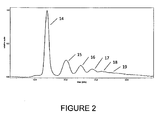
- Figure 2 shows the 90° light scattering signal as a function of time from a bovine serum albumin, BSA, sample fractionated by an A4F device.
- BSA bovine serum albumin
- the resolved peaks include certain so-called oligomers that are small 2-, 3-, 4-, and 5-mer aggregates of the monomer, respectively.
- the major peak at 14 corresponds to the monomer fraction.
- Pharmaceutical products, somewhat similar to this protein example, must be produced in such a manner that the amount of aggregated monomer is negligible. Although such oligomers do not contribute generally to the biological's therapeutic activity, their presence should be minimized. Of even greater importance are much larger aggregates that may cause immunogenic responses in the patient. In this manner, the biological becomes dangerous to the patient and must be cleared of such possible contributions.
- An objective of this invention is to show how this might be achieved.
- the width of the eluting peaks of Fig. 2 Note the width of the eluting peaks of Fig. 2 .
- Another objective of this invention is to separate and concentrate such contributions for later collection and analyses.
- immunogenic contributions are known to be present, the product cannot be sold and is generally destroyed.
- these contaminants could be removed, the product might then be considered safe and could be marketed as such.
- An additional objective of this invention is to be able to restore such contaminated pharmaceutical products to pristine, safe, and marketable states.
- FIG. 3 illustrates such a channel 6 cut into a spacer 5 of length L, initial width 2 w 0 , and final width 2 w L .
- F c cr A
- c cr is the total cross flow through the channel-defined membrane
- ⁇ 0 is the input flow rate
- A is the area of the channel from 0 to L.
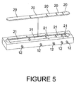
- each region 20 is a corresponding partitioned compartment 21 through whose base is an exit port fitting 12 .
- a plurality of programmable regulators, one for each compartment/region, are located in an external control unit. Needle valves combined with flow meter regulation are often selected for this purpose. As the cross flow through each region may be individually programmed in time, the inventive system provides a broad range of capabilities. Larger particles, once separated from their smaller companions, may be retained at a particular region while the smaller particles progress through the channel. Another feature would relate to the invention's ability to reconcentrate separated species that had become broadened and diluted. It is important recognize that the regions and their associated compartments may be of different sizes and, under some circumstances, might not be transverse to the direction of flow. Figure 5 shows an example of different compartment and frit configurations.
- FIG. 4 wherein the preferred embodiment is illustrated by a channel comprised of 5 equally sized regions, each with its corresponding compartment below, means by which the embodiment may be restored to its conventional form is readily visualized.
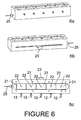
- Figures 6 and 7 suggest how the base of each compartment could be modified to incorporate a drain hole 22 at its base; each such drain emptying into a common compartment 24 below. By opening all such drains and closing each needle valve that controls out flow through the individual port fittings 12 , the common single compartment is provided with a single port fitting 12 whose out flow is controlled by a single regulator in the controller unit. The channel would thus be restored for conventional operation.
- the paddle structure 23 that may be slid out partially, opening thereby all drain holes 22 directing fluid to flow into the common compartment 24 and out through the associated out flow port fitting 12 .
- This concept may be further expanded to permit compartmental ganging to be applied to selected sets of compartments whose cross flows per unit area may be required to be the same.
- their regulators would be closed and their drainage valves opened by individual paddle features similar to the multi drain hole paddle structure 23 allowing drainage into the common compartment 24 controlled by its single port fitting 12 shown at the left of the structure in a plane at right angles to the individual compartment out flow fittings.
- Fig. 6 The structure of Fig. 6 is shown in further detail by means of the cross sectional cut through the compartmentalized structure indicated in Figs. 7a and 7b .
- the out flow port fittings 12 of each compartment are shown in Fig. 6a .
- Fig. 6a is very similar to the base of the unit of Fig. 4 but with the addition of a single out flow port fitting 12 serving the common compartment 24 .
- restoration to conventional operation may be achieved by displacing the paddle element 23 and stopping all individual flows through their port fittings 12 , it would be far easier for most experimental requirements just to replace the compartmentalized structure with a conventional cross flow unit.
- the main and most important reason that one might want to be able to restore the channel by repositioning the drain hole blocking paddle 23 illustrated in Figs.
- FIG. 4 illustrates the invention by means of a five compartment configuration
- similar systems may be developed using more or even fewer compartments of similar or different sizes.
- Means to gang different groups of compartments are easily implemented.
- the first three and the fifth compartments might be controlled by a single regulating valve following the closure of their outflow port fittings 12 and the opening of their corresponding drainage holes into a single volume, while the fourth compartment could be controlled by a single valve controlling its outflow.
- FIG. 8 illustrates the structure and key elements of the porous hollow fiber fractionator.
- a rigid vessel 25 surrounds a porous cylindrical fiber 26 mounted therein between an inlet fitting 27 and exit port fitting 29 .
- the mobile phase is introduced through fitting 27 and samples are injected into the mobile phase through injection port fitting 28 .
- the flow through the porous fiber channel 26 is comprised of two parts: transverse flow through the porous fiber and the longitudinal flow.”Thus the fiber plays the role of the membrane/frit structure of the A4F and SF1FFF fractionators.
- Figure 9 illustrates how a porous hollow fiber fractionator, H4F, might be modified to permit compartmentalization similar to the A4F implementation.
- the internal structure of the modified rigid vessel 25 is divided into compartments 21 surrounding a porous fiber 26 threaded therethrough.
- the fiber may be cooled to shrink slightly before insertion producing a tight fit against the side walls of each compartment upon heating. Additionally, the internal pressure caused by the longitudinally flowing fluid therein may be sufficient to seal each compartment.
- circular O-rings may be inserted into each.
- Other implementations would include a compartmentalized vessel that is hinged into two axial components that are easily opened and provided with suitable seals and O-rings required for adequate sealing of each compartment.
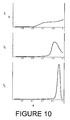
- Figure 10 illustrates how the inventive technique might be used to examine the larger aggregates 19 of the sample shown in Fig. 2 . Assume that an objective of this separation is to isolate and concentrate these larger aggregates 19 present from the most prominent oligomeric states.
- the unresolved aggregate fraction 19 has been further separated from the well defined and characterized oligomeric constituents. Once released, the aggregate fraction may be subjected to further analyses and study.
- the membrane used for separations within a compartmentalized fractionator has been assumed of uniform composition, as have the individual frit elements, these constituents may be constructed with materials of different composition.
- the membrane 4 of the A4F fractionators and, its compartmentalized variants may be constructed of segmented sections fused or otherwise connected between regions. One segment, for example could be non porous preventing thereby any cross flow affecting the sample passing therethrough.
- Other membrane sections may be composed of sections with differing porosities.
- the supporting frits, as well, may be of differing compositions expanding or restricting thereby the flow therethrough. Consider a frit section composed of a highly porous material permeable to a broad range of molecular/particle sizes that might pass therethrough unimpeded.
- any sample passing thereover at a particular time may be driven almost entirely therethrough by applying a strong cross flow as it reaches that porous section.
- Other cross flows at different compartments may be modified accordingly to establish means by which specific fractions of the separating sample may be collected and removed from therefrom.
- Another interesting application of a simple compartmentalized fractionator would be one designed to collect specifically defined fractions of a sample undergoing separation.
- the final compartment be operated independently in this manner with its corresponding membrane section almost completely permeable to any sample fraction that might pass therethrough.
- cross flow would be prevented from passing through this section. Only when a specific fraction had reached it, would the cross flow be activated briefly and the fraction swept into its companion chamber. Since such a fractionator chamber may be of extremely small volume, other easily developed means may be required to extract such collected samples without their appreciable dilution.
Landscapes
- Physics & Mathematics (AREA)
- Health & Medical Sciences (AREA)
- Life Sciences & Earth Sciences (AREA)
- Chemical & Material Sciences (AREA)
- Analytical Chemistry (AREA)
- Biochemistry (AREA)
- General Health & Medical Sciences (AREA)
- General Physics & Mathematics (AREA)
- Immunology (AREA)
- Pathology (AREA)
- Separation Using Semi-Permeable Membranes (AREA)
- Sampling And Sample Adjustment (AREA)
- Physical Or Chemical Processes And Apparatus (AREA)
Claims (16)
- Feldflussfraktionierer mit einer Kanaleinhausungseinrichtung, welcher aufweist:einen Kanal (6), der von begrenzenden Flächen an allen Seiten begrenzt wird;wobei mindestens eine der begrenzenden Flächen eine Anreicherungswand (2, 4) mit einer porösen Struktur aufweist;Anschlussmittel (9, 11), um einen mobilen Phasenfluss entlang des Kanals (6) vorzusehen und zu regeln; undeine Einrichtung (10) zur Eingabe eines Probenaliquot in die mobile Phase;dadurch gekennzeichnet, dassdie Anreicherungswand (2, 4) in unterschiedliche Bereiche (20) unterteilt ist;eine Vielzahl von separaten Kompartments (21) entlang der Länge des Kanals (6) angeordnet ist, so dass ein quer zum Fluss entlang des Kanals (6) fließender Teil der mobilen Phase durch jeden unterschiedlichen Bereich (20) der Anreicherungswand (2, 4) in ein oder mehrere separate Kompartments (21) fließen kann; undjedes Kompartment (21) mit unabhängigen Anschlussmitteln (12) zur Regelung des quer verlaufenden Flusses eines Teils der mobilen Phase dort hinein versehen ist.
- Feldflussfraktionierer nach Anspruch 1, bei welchem die Kanaleinhausungseinrichtung außerdem aufweist
eine Grundplatte (1), die eine Gruppe von separaten Kompartments enthält, die von oben offen und so ausgebildet sind, dass sie innerhalb der Grundplatte (2) liegen, wobei die Kompartments (21) allesamt in derselben Ebene parallel zur Basis der Grundplatte (2) liegen;
eine permeable Fritte (2), die die Grundplatte (1) bedeckt;
eine permeable Membran (4), die die Fritte (2) bedeckt, wobei die permeable Membran und die Fritte die Anreicherungswand aufweisen;
wobei die Fritte in unterschiedliche Bereiche (20) unterteilt ist, von denen jeder Bereich (20) ein zugehöriges Kompartment (21) darunter bedeckt;
ein Abstandselement (5) auf der Oberseite der permeablen Membran (4), aus welchem eine Sektion herausgeschnitten ist, die den Kanal (6) bildet, der an allen seinen Seiten vom übrigen Bereich des Abstandselementes (5) begrenzt wird, wobei die ausgeschnittene Sektion die Bereiche (20) der unterhalb der permeablen Membran (4) liegenden Fritte (2) überspannt;
eine obere Platte (8), die auf der Oberseite des Abstandselementes (5) liegt, die ausgeschnittene Sektion abdichtet und drei Anschlüsse (9, 10, 11) aufweist, die in geeigneter Weise über dem Kanal (6) angeordnet sind, um der Reihe nach einen Fluss durch eine mobile Phase, eine Injektion des Probenaliqot und einen Ausfluss der Probe zu ermöglichen, die durch den Kanal (6) aufgrund des mobilen Phasenflusses getrieben worden ist; und
ein Dichtungsmittel (3), durch das in den Kanal (6) eingegebenes Fluid an einem Fluss durch diesen oder quer zu diesem durch die permeable Membran (4) und die Fritte (2) in die darunterliegenden Kompartments (21) gehindert wird. - Feldflussfraktionierer nach Anspruch 1 oder 2, bei welchem die Anschlusseinrichtung aufweist
einen Auslassanschluss (12) an der Basis jedes Kompartments (21), der einen Ausfluss des Fluids aus diesem ermöglicht, das durch die permeable Membran (4) und einen zugehörigen Bereich (20) der darüberliegenden Fritte (2) eingedrungen ist; und
eine Fluidverbindungseinrichtung (24) zwischen jedem derartigen Auslassanschluss (12) und einer unabhängigen Fluidflusssteuerungseinrichtung, wodurch der Ausfluss aus jedem entsprechenden Kompartment (21) gesteuert werden kann, um dadurch die unabhängige Steuerung eines entsprechenden Querflusses am Probenaliquot zu ermöglichen, und zwar bei Bewegung über das entsprechende Kompartment (21), um auf diese Weise unabhängig voneinander Querflussfelder an jedem segmentierten Bereich des Kanals (6) zu bilden. - Symmetrische Flussimplementierung des Feldflussfraktionierers von Anspruch 2, wobei das obere Plattenelement aus einer permeablen Fritte besteht, durch die ein sekundärer Fluss bestehend aus einer mobilen Phase rechtwinklig zum Kanalfluss gepumpt wird, wobei der sekundäre Fluss eine Quelle von sämtlichen Querflussanforderungen der segmentierten Bereiche bildet.
- Asymmetrische Flussimplementierung des Feldflussfraktionierers von Anspruch 2, bei welcher die obere Platte (8) undurchlässig ist und sämtliche für alle gesteuerten segmentierten Regionen (20) erforderlichen Querflussquellen durch Einschränkung des Kanalausflusses gebildet werden, so dass die Differenz zwischen dem Eintritt in den Kanal und dem Ausfluss aus diesem Kanal gleich dem gesamten Querfluss aller segmentierten Bereiche (20) ist.
- Hohlfaserflussimplementierung des Feldflussfraktionierers von Anspruch 1, bei welcher die an allen Seiten begrenzte Kanaleinhausungseinrichtung eine permeable Hohlfaser aufweist.
- Feldflussfraktionierer nach Anspruch 1, bei welchem die permeable Membran in Bereiche unterschiedlicher Permeabilität segmentiert ist.
- Feldflussfraktionierer nach Anspruch 6, bei welchem die Hohlfaser aus unterschiedlichen Segmenten mit unterschiedlicher Permeabilität besteht.
- Verfahren zur Fraktionierung und Verarbeitung eines flüssigen Aliquot, das Partikel variierender Größen und Zusammensetzungen enthält, mit den Schritten, das zu verarbeitende Aliquot auszuwählen;
eine Kanaleinhausungseinrichtung mit einem Anschluss (9), durch den eine mobile Phase kontinuierliche eintreten und entlang eines Kanals (6) fließen kann, einem Injektionsanschluss (10), durch den das Aliquot in die mobile Phase injiziert wird, einem Auslassanschluss (11), durch den Bestandteile des Aliquots den Kanal (6) nach Zusammenwirken mit diesem verlassen können, und einer Anreicherungswand (2, 4) mit einer porösen Struktur, durch die ein quer zum Fluss entlang des Kanals (6) fließender Teil der mobilen Phase treten kann, vorzusehen;
das Aliquot in die mobile Phase zu injizieren; und
das verarbeitete Aliquot zu sammeln;
dadurch gekennzeichnet, dass
die Anreicherungswand (2, 4) in eine Vielzahl von unterschiedlichen Bereichen (20) unterteilt ist und der Fluss eines Teils der mobilen Phase quer hierzu jeweils durch einen unterschiedlichen Bereich (20) der Anreicherungswand (2, 4) in ein separates Kompartment (21) stattfindet, wobei jedes Kompartment mit unabhängigen Mitteln (12) zur Regelung des in dieses führenden Querflusses versehen ist; und
diese Mittel (12) gesteuert werden, um einen Querfluss eines Teils der mobilen Phase in jedes Kompartment (21) zur Erzielung einer gewünschten Verarbeitung des Aliquot zu regeln. - Verfahren nach Anspruch 9, bei welchem die Kanaleinhausungseinrichtung ferner aufweist
eine Grundplatte (1), die die Kompartments (21) enthält, welche von oben offen und so ausgebildet sind, dass sie innerhalb der Grundplatte (1) liegen, wobei die Öffnungen allesamt in derselben Ebene parallel zur Basis der Grundplatte (1) liegen,
eine permeable segmentierte Fritte (2), die auf der Oberseite der Kompartmentöffnungen in der Grundplatte (1) liegt, wobei jedes Frittensegment ein darunter befindliches zugehöriges Kompartment (21) bedeckt;
eine permeable Membran (4), die die segmentierte Fritte (2) bedeckt, wobei die Fritte (2) und die Membran (4) als Anreicherungswand wirken;
ein Abstandselement (5) auf der Oberseite der permeablen Membran (4), aus welchem eine Sektion herausgeschnitten ist, um dadurch einen ausgeschnittenen Kanalbereich (6) zu bilden, der an allen Seiten vom übrigen Bereich des Abstandselementes (5) begrenzt wird, wobei der ausgeschnittene Bereich die unter der permeablen Membran (4) liegende segmentierte Fritte (2) überspannt; eine obere Platte (8), die auf der Oberseite des Abstandselementes (2) liegt, den daraus ausgeschnittenen Kanalbereich (6) abdichtet und Anschlüsse (9, 10, 11) enthält, die in geeigneter Weise über dem ausgeschnittenen Kanal (6) angeordnet sind, um der Reihe nach einen Fluss durch eine mobile Phase, eine Injektion des Probenaliquot und einen Ausfluss der Probe, die durch den Kanal (6) aufgrund des Flusses der mobilen Phase getrieben worden ist, zu ermöglichen; und ein Dichtungsmittel (3), durch das in den Kanal (6) eingegebenes Fluid an einem Fluss durch diesen oder quer zu diesem durch die permeable Membran (4) und die tragende Fritte (2) in die Kompartments (21) darunter gehindert wird. - Verfahren nach Anspruch 9, bei welchem der Kanal aus einer permeablen Hohlfaser besteht, wobei die mobile Phase entlang des inneren Volumens der Hohlfaser geleitet wird und die Innenfläche der Hohlfaser als Anreicherungswand wirkt.
- Verfahren nach Anspruch 9, bei welchem die Verarbeitung des Aliquot darin besteht, eine flüssigkeitsgetragene Probe durch Separierung von großen Aggregaten aus der Probe zu reinigen, mit den weiteren Schritten,
den Querfluss der mobilen Phase in ein oder mehrere Kompartments (21) so einzustellen, dass größere Aggregate innerhalb des Kanals (6) zurückgehalten werden;
der übrigen Probe einen Austritt durch den Auslassanschluss (11) zu ermöglichen; und
die gereinigte Probe zu sammeln, aus der die großen Aggregate separiert worden sind. - Verfahren nach Anspruch 9, bei welchem das Aliquot verarbeitet wird, um Partikel von spezifischen Größen durch Steuerung geeigneter segmentierter Querflussfelder aus diesem zu separieren.
- Verfahren nach Anspruch 13, mit den weiteren Schritten,
den Querfluss der mobilen Phase in ein oder mehrere Kompartments (21) einzustellen, so dass die Partikel oberhalb des unteren Schwellwertes eines ausgewählten Größenbereiches innerhalb des Kanals (6) zurückgehalten oder verzögert werden;
der übrigen Probe der Partikel unterhalb des ausgewählten Größenbereiches den Austritt durch den Auslassanschluss (11) zu ermöglichen;
den Querfluss der mobilen Phase in ein oder mehrere Kompartments (21) so einzustellen, dass sich die übrigen Partikel innerhalb des Kanals (6) über seine Länge fortbewegen;
den Querfluss der mobilen Phase in ein oder mehrere Kompartments (21) so einzustellen, dass die Partikel oberhalb des oberen Schwellwertes des ausgewählten Größenbereiches innerhalb des Kanals (6) zurückgehalten oder verzögert werden, wodurch den Partikeln innerhalb des ausgewählten Größenbereiches ein Austritt durch den Auslassanschluss (11) ermöglicht wird; und
die Probe der Partikel innerhalb des ausgewählten Größenbereiches zu sammeln. - Verfahren nach Anspruch 9, bei welchem das Aliquot verarbeitet wird, um Partikel innerhalb einer Probe oberhalb eines spezifischen Größenbereiches innerhalb einer Flüssigkeit zu konzentrieren, mit den weiteren Schritten,
die Querflüsse der mobilen Phase in ein oder mehrere Kompartments (21) so einzustellen, dass die Partikel oberhalb des Schwellwertes eines ausgewählten Größenbereiches innerhalb des Kanals (6) zurückgehalten oder verzögert werden;
der übrigen Probe einen Austritt durch den Auslassanschluss(11) zu ermöglichen;
die Querflüsse in die Kompartments (21) so einzustellen, dass die zurückgehaltenen oder verzögerten Partikel gelöst werden und ihnen ein Austritt aus dem Kanal (6) durch den Auslassanschluss (11) ermöglicht wird; und
die Probe von Partikeln innerhalb des ausgewählten Größenbereiches zu sammeln. - Verfahren nach Anspruch 9, bei welchem ein oder mehrere Bereiche der Anreicherungswand (2, 4) angemessen permeabel ist, um Partikeln eines gewünschten Größenbereiches innerhalb des flüssigen Aliquot eine Durchleitung durch diese zu ermöglichen, mit dem weiteren Schritt, den Querfluss in das an den ausreichend permeablen Bereich der Anreicherungswand (2, 4) angrenzende Kompartment so einzustellen, dass kein Fluid dort hinein fließt, bis ein Durchfluss der gewünschten spezifischen Fraktion stattfindet, wenn der Querfluss in dieses Kompartment (21) ansteigt, so dass sich die gewünschte Fraktion dort hinein bewegt.
Applications Claiming Priority (1)
| Application Number | Priority Date | Filing Date | Title |
|---|---|---|---|
| US12/790,707 US8163182B2 (en) | 2010-05-28 | 2010-05-28 | Compartmentalized field flow fractionation |
Publications (2)
| Publication Number | Publication Date |
|---|---|
| EP2390660A1 EP2390660A1 (de) | 2011-11-30 |
| EP2390660B1 true EP2390660B1 (de) | 2015-11-25 |
Family
ID=43978006
Family Applications (1)
| Application Number | Title | Priority Date | Filing Date |
|---|---|---|---|
| EP10196730.5A Not-in-force EP2390660B1 (de) | 2010-05-28 | 2010-12-23 | Flussfraktionierung in einem kompartimentierten Kanal |
Country Status (4)
| Country | Link |
|---|---|
| US (3) | US8163182B2 (de) |
| EP (1) | EP2390660B1 (de) |
| JP (1) | JP5960948B2 (de) |
| CN (1) | CN106501379A (de) |
Cited By (1)
| Publication number | Priority date | Publication date | Assignee | Title |
|---|---|---|---|---|
| EP3531125A1 (de) | 2018-02-22 | 2019-08-28 | Assistance Publique, Hopitaux De Paris | Mikrofluidische vorrichtung zur asymmetrischen fluss feld-fluss fraktionierung und verfahren zu deren verwendung |
Families Citing this family (15)
| Publication number | Priority date | Publication date | Assignee | Title |
|---|---|---|---|---|
| US10048233B2 (en) * | 2012-11-12 | 2018-08-14 | Dionex Corporation | Suppressor device |
| US9914651B2 (en) | 2013-05-08 | 2018-03-13 | Dionex Corporation | Current efficient electrolytic device and method |
| US10175211B2 (en) | 2014-12-31 | 2019-01-08 | Dionex Corporation | Current-efficient suppressor and pretreatment device and method |
| WO2018165627A1 (en) * | 2017-03-09 | 2018-09-13 | Wyatt Technology Corporation | Injecting a liquid borne sample into a field flow fractionator |
| JP7294772B2 (ja) | 2018-04-11 | 2023-06-20 | 株式会社島津製作所 | フィールドフローフラクショネーション装置 |
| CN112384302A (zh) * | 2018-07-17 | 2021-02-19 | 株式会社岛津制作所 | 场流分离装置 |
| US11754569B2 (en) * | 2018-08-30 | 2023-09-12 | Regeneron Pharmaceuticals, Inc. | Methods for characterizing protein complexes |
| US10864483B2 (en) | 2018-11-16 | 2020-12-15 | Integrated Protein Technologies, Snc. | Molecular weight filtration system and apparatus |
| US20230061570A1 (en) * | 2021-08-24 | 2023-03-02 | Integrated Protein Technologies, Inc. | Housed consumable for use with molecular weight filtration system and apparatus |
| US11243194B2 (en) | 2019-01-25 | 2022-02-08 | Dionex Corporation | Suppressors with eluent screens for use in ion chromatography |
| US11971392B2 (en) * | 2019-06-25 | 2024-04-30 | Wyatt Technology, Llc | Sealing structure for a field flow fractionator |
| JP7215366B2 (ja) * | 2019-07-17 | 2023-01-31 | 株式会社島津製作所 | 非対称流流動場分画装置 |
| US20220118407A1 (en) * | 2020-10-19 | 2022-04-21 | Wyatt Technology Corporation | Electrical field flow fractionator |
| US11890580B2 (en) * | 2020-11-02 | 2024-02-06 | Wyatt Technology, Llc | Field flow fractionator |
| US12313606B2 (en) * | 2021-11-02 | 2025-05-27 | Wyatt Technology, Llc | Field flow fractionator configured to prevent leakage |
Family Cites Families (19)
| Publication number | Priority date | Publication date | Assignee | Title |
|---|---|---|---|---|
| US4440638A (en) | 1982-02-16 | 1984-04-03 | U.T. Board Of Regents | Surface field-effect device for manipulation of charged species |
| US5141651A (en) * | 1989-06-12 | 1992-08-25 | University Of Utah | Pinched channel inlet system for reduced relaxation effects and stopless flow injection in field-flow fractionation |
| US5193688A (en) * | 1989-12-08 | 1993-03-16 | University Of Utah | Method and apparatus for hydrodynamic relaxation and sample concentration NIN field-flow fraction using permeable wall elements |
| JPH06130035A (ja) * | 1992-10-15 | 1994-05-13 | Mitsubishi Heavy Ind Ltd | 多段型電気泳動装置 |
| US6387707B1 (en) * | 1996-04-25 | 2002-05-14 | Bioarray Solutions | Array Cytometry |
| US6109119A (en) * | 1998-02-27 | 2000-08-29 | Fffractionation, Llc | Sample focusing device and method |
| US6294063B1 (en) | 1999-02-12 | 2001-09-25 | Board Of Regents, The University Of Texas System | Method and apparatus for programmable fluidic processing |
| AU2001271330A1 (en) * | 2000-06-14 | 2001-12-24 | Board Of Regents, The University Of Texas System | Method and apparatus for combined magnetophoretic and dielectrophoretic manipulation of analyte mixtures |
| ATE304174T1 (de) | 2000-06-14 | 2005-09-15 | Univ Texas | Systeme und verfahren zur zellteilbevölkerungsanalyse |
| US20040000519A1 (en) * | 2002-06-28 | 2004-01-01 | Postnova Analytics, Inc. | Field-flow fractionation method and apparatus |
| US6905029B2 (en) * | 2002-09-12 | 2005-06-14 | California Institute Of Technology | Cross-flow differential migration classifier |
| US6774994B1 (en) | 2003-08-13 | 2004-08-10 | Wyatt Technology Corporation | Method and apparatus for determining absolute number densities of particles in suspension |
| US7811438B2 (en) * | 2004-12-08 | 2010-10-12 | Palo Alto Research Center Incorporated | Bio-enrichment device to enhance sample collection and detection |
| WO2006063625A1 (en) | 2004-12-17 | 2006-06-22 | Agilent Technologies, Inc. | Fractionation using electro elution |
| KR100792683B1 (ko) * | 2006-05-09 | 2008-01-09 | 연세대학교 산학협력단 | 모세관등전집중-중공사흐름장흐름분획법을 이용한 단백질분리장치 및 분리방법 |
| JP4770603B2 (ja) * | 2006-06-26 | 2011-09-14 | 株式会社島津製作所 | フィールドフローフラクショネーション装置 |
| DE102007047695A1 (de) * | 2007-10-05 | 2009-04-09 | Wyatt Technology Europe Gmbh | Verfahren zur Optimierung der Trennmethode für ein gegebenes Probensystem mittels asymmetrischer Feldflussfraktionierung |
| WO2009146143A2 (en) * | 2008-04-03 | 2009-12-03 | The Regents Of The University Of California | Ex-vivo multi-dimensional system for the separation and isolation of cells, vesicles, nanoparticles and biomarkers |
| US8360244B2 (en) * | 2008-06-09 | 2013-01-29 | Wyatt Technology Corporation | Method and apparatus for optimizing the separation of small particles using the asymmetric flow field flow fractionation method |
-
2010
- 2010-05-28 US US12/790,707 patent/US8163182B2/en active Active
- 2010-12-23 EP EP10196730.5A patent/EP2390660B1/de not_active Not-in-force
-
2011
- 2011-02-10 CN CN201610922476.XA patent/CN106501379A/zh active Pending
- 2011-03-08 JP JP2011049765A patent/JP5960948B2/ja not_active Expired - Fee Related
-
2012
- 2012-02-21 US US13/401,465 patent/US8206590B1/en not_active Expired - Fee Related
- 2012-02-21 US US13/401,511 patent/US8333891B2/en not_active Expired - Fee Related
Cited By (3)
| Publication number | Priority date | Publication date | Assignee | Title |
|---|---|---|---|---|
| EP3531125A1 (de) | 2018-02-22 | 2019-08-28 | Assistance Publique, Hopitaux De Paris | Mikrofluidische vorrichtung zur asymmetrischen fluss feld-fluss fraktionierung und verfahren zu deren verwendung |
| WO2019162404A1 (en) | 2018-02-22 | 2019-08-29 | Assistance Publique - Hopitaux De Paris | Microfluidic asymmetric flow field-flow fractionation device and method of using the same |
| US11946909B2 (en) | 2018-02-22 | 2024-04-02 | Assistance Publique-Hopitaux De Paris | Microfluidic asymmetric flow field-flow fractionation device and method of using the same |
Also Published As
| Publication number | Publication date |
|---|---|
| JP2011247874A (ja) | 2011-12-08 |
| EP2390660A1 (de) | 2011-11-30 |
| US20120148460A1 (en) | 2012-06-14 |
| US20120144900A1 (en) | 2012-06-14 |
| US20110290724A1 (en) | 2011-12-01 |
| JP5960948B2 (ja) | 2016-08-02 |
| US8333891B2 (en) | 2012-12-18 |
| CN106501379A (zh) | 2017-03-15 |
| CN102262007A (zh) | 2011-11-30 |
| US8163182B2 (en) | 2012-04-24 |
| US8206590B1 (en) | 2012-06-26 |
Similar Documents
| Publication | Publication Date | Title |
|---|---|---|
| US8163182B2 (en) | Compartmentalized field flow fractionation | |
| US11644446B2 (en) | Injecting a liquid borne sample into a field flow fractionator | |
| US5193688A (en) | Method and apparatus for hydrodynamic relaxation and sample concentration NIN field-flow fraction using permeable wall elements | |
| US4147621A (en) | Method and apparatus for flow field-flow fractionation | |
| US8360244B2 (en) | Method and apparatus for optimizing the separation of small particles using the asymmetric flow field flow fractionation method | |
| US6365050B1 (en) | Method for stopless and splitless flow field-flow fractionation | |
| US11971392B2 (en) | Sealing structure for a field flow fractionator | |
| US11890580B2 (en) | Field flow fractionator | |
| DE102015202667A1 (de) | Vorrichtung für die Feldflussfraktionierung | |
| US6109119A (en) | Sample focusing device and method | |
| DE112018000184T5 (de) | Automatisierte Maschine zum Sortieren biologischer Flüssigkeiten | |
| Granger et al. | Flow and diffusion of particles in a channel with one porous wall: polarization chromatography | |
| Kim et al. | Development of a multilane channel system for nongel-based two-dimensional protein separations using isoelectric focusing and asymmetrical flow field-flow fractionation | |
| Giddings et al. | Outlet stream splitting for sample concentration in field-flow fractionation | |
| US20250296019A1 (en) | System and method for automatically separating out target objects designed to not be exposed to outside | |
| Moon et al. | Retention and efficiency in frit-inlet asymmetrical flow field-flow fractionation | |
| DE19808992C2 (de) | Kanalvorrichtung für die Feldflußfraktionierung | |
| CN102262007B (zh) | 间隔化场流分级 | |
| EP1432490B1 (de) | Verfahren zur trennung von suspensionen und vorrichtung | |
| EP4409276A1 (de) | Verwaltung eines mit einem feldflussfraktionierer assoziierten lösungsmittels | |
| Lee et al. | Evaluation of multiplexed hollow fiber flow field-flow fractionation for semi-preparative purposes | |
| JP2025537143A (ja) | フィールドフローフラクショネータ | |
| DE19709250C1 (de) | Asymmetrische Fluß-Feldflußfraktionierungs-Vorrichtung | |
| US20220113286A1 (en) | Regulating a channel temperature of a field flow fractionator | |
| Rathore et al. | Optimization, scale-up, and validation ISSUES in FILTRATION of Biopharmaceuticals, Part II |
Legal Events
| Date | Code | Title | Description |
|---|---|---|---|
| AK | Designated contracting states |
Kind code of ref document: A1 Designated state(s): AL AT BE BG CH CY CZ DE DK EE ES FI FR GB GR HR HU IE IS IT LI LT LU LV MC MK MT NL NO PL PT RO RS SE SI SK SM TR |
|
| AX | Request for extension of the european patent |
Extension state: BA ME |
|
| PUAI | Public reference made under article 153(3) epc to a published international application that has entered the european phase |
Free format text: ORIGINAL CODE: 0009012 |
|
| 17P | Request for examination filed |
Effective date: 20120530 |
|
| GRAP | Despatch of communication of intention to grant a patent |
Free format text: ORIGINAL CODE: EPIDOSNIGR1 |
|
| INTG | Intention to grant announced |
Effective date: 20150601 |
|
| GRAS | Grant fee paid |
Free format text: ORIGINAL CODE: EPIDOSNIGR3 |
|
| GRAA | (expected) grant |
Free format text: ORIGINAL CODE: 0009210 |
|
| AK | Designated contracting states |
Kind code of ref document: B1 Designated state(s): AL AT BE BG CH CY CZ DE DK EE ES FI FR GB GR HR HU IE IS IT LI LT LU LV MC MK MT NL NO PL PT RO RS SE SI SK SM TR |
|
| REG | Reference to a national code |
Ref country code: GB Ref legal event code: FG4D |
|
| REG | Reference to a national code |
Ref country code: CH Ref legal event code: EP |
|
| REG | Reference to a national code |
Ref country code: AT Ref legal event code: REF Ref document number: 762861 Country of ref document: AT Kind code of ref document: T Effective date: 20151215 |
|
| REG | Reference to a national code |
Ref country code: IE Ref legal event code: FG4D |
|
| REG | Reference to a national code |
Ref country code: FR Ref legal event code: PLFP Year of fee payment: 6 |
|
| REG | Reference to a national code |
Ref country code: DE Ref legal event code: R096 Ref document number: 602010029146 Country of ref document: DE |
|
| REG | Reference to a national code |
Ref country code: LT Ref legal event code: MG4D |
|
| REG | Reference to a national code |
Ref country code: NL Ref legal event code: MP Effective date: 20160225 |
|
| REG | Reference to a national code |
Ref country code: AT Ref legal event code: MK05 Ref document number: 762861 Country of ref document: AT Kind code of ref document: T Effective date: 20151125 |
|
| PG25 | Lapsed in a contracting state [announced via postgrant information from national office to epo] |
Ref country code: NO Free format text: LAPSE BECAUSE OF FAILURE TO SUBMIT A TRANSLATION OF THE DESCRIPTION OR TO PAY THE FEE WITHIN THE PRESCRIBED TIME-LIMIT Effective date: 20160225 Ref country code: LT Free format text: LAPSE BECAUSE OF FAILURE TO SUBMIT A TRANSLATION OF THE DESCRIPTION OR TO PAY THE FEE WITHIN THE PRESCRIBED TIME-LIMIT Effective date: 20151125 Ref country code: NL Free format text: LAPSE BECAUSE OF FAILURE TO SUBMIT A TRANSLATION OF THE DESCRIPTION OR TO PAY THE FEE WITHIN THE PRESCRIBED TIME-LIMIT Effective date: 20151125 Ref country code: HR Free format text: LAPSE BECAUSE OF FAILURE TO SUBMIT A TRANSLATION OF THE DESCRIPTION OR TO PAY THE FEE WITHIN THE PRESCRIBED TIME-LIMIT Effective date: 20151125 Ref country code: IS Free format text: LAPSE BECAUSE OF FAILURE TO SUBMIT A TRANSLATION OF THE DESCRIPTION OR TO PAY THE FEE WITHIN THE PRESCRIBED TIME-LIMIT Effective date: 20160325 Ref country code: ES Free format text: LAPSE BECAUSE OF FAILURE TO SUBMIT A TRANSLATION OF THE DESCRIPTION OR TO PAY THE FEE WITHIN THE PRESCRIBED TIME-LIMIT Effective date: 20151125 |
|
| PG25 | Lapsed in a contracting state [announced via postgrant information from national office to epo] |
Ref country code: PL Free format text: LAPSE BECAUSE OF FAILURE TO SUBMIT A TRANSLATION OF THE DESCRIPTION OR TO PAY THE FEE WITHIN THE PRESCRIBED TIME-LIMIT Effective date: 20151125 Ref country code: LV Free format text: LAPSE BECAUSE OF FAILURE TO SUBMIT A TRANSLATION OF THE DESCRIPTION OR TO PAY THE FEE WITHIN THE PRESCRIBED TIME-LIMIT Effective date: 20151125 Ref country code: GR Free format text: LAPSE BECAUSE OF FAILURE TO SUBMIT A TRANSLATION OF THE DESCRIPTION OR TO PAY THE FEE WITHIN THE PRESCRIBED TIME-LIMIT Effective date: 20160226 Ref country code: PT Free format text: LAPSE BECAUSE OF FAILURE TO SUBMIT A TRANSLATION OF THE DESCRIPTION OR TO PAY THE FEE WITHIN THE PRESCRIBED TIME-LIMIT Effective date: 20160325 Ref country code: BE Free format text: LAPSE BECAUSE OF NON-PAYMENT OF DUE FEES Effective date: 20151231 Ref country code: AT Free format text: LAPSE BECAUSE OF FAILURE TO SUBMIT A TRANSLATION OF THE DESCRIPTION OR TO PAY THE FEE WITHIN THE PRESCRIBED TIME-LIMIT Effective date: 20151125 Ref country code: SE Free format text: LAPSE BECAUSE OF FAILURE TO SUBMIT A TRANSLATION OF THE DESCRIPTION OR TO PAY THE FEE WITHIN THE PRESCRIBED TIME-LIMIT Effective date: 20151125 Ref country code: RS Free format text: LAPSE BECAUSE OF FAILURE TO SUBMIT A TRANSLATION OF THE DESCRIPTION OR TO PAY THE FEE WITHIN THE PRESCRIBED TIME-LIMIT Effective date: 20151125 Ref country code: FI Free format text: LAPSE BECAUSE OF FAILURE TO SUBMIT A TRANSLATION OF THE DESCRIPTION OR TO PAY THE FEE WITHIN THE PRESCRIBED TIME-LIMIT Effective date: 20151125 |
|
| PG25 | Lapsed in a contracting state [announced via postgrant information from national office to epo] |
Ref country code: CZ Free format text: LAPSE BECAUSE OF FAILURE TO SUBMIT A TRANSLATION OF THE DESCRIPTION OR TO PAY THE FEE WITHIN THE PRESCRIBED TIME-LIMIT Effective date: 20151125 Ref country code: IT Free format text: LAPSE BECAUSE OF FAILURE TO SUBMIT A TRANSLATION OF THE DESCRIPTION OR TO PAY THE FEE WITHIN THE PRESCRIBED TIME-LIMIT Effective date: 20151125 |
|
| REG | Reference to a national code |
Ref country code: CH Ref legal event code: PL |
|
| REG | Reference to a national code |
Ref country code: DE Ref legal event code: R097 Ref document number: 602010029146 Country of ref document: DE |
|
| PG25 | Lapsed in a contracting state [announced via postgrant information from national office to epo] |
Ref country code: EE Free format text: LAPSE BECAUSE OF FAILURE TO SUBMIT A TRANSLATION OF THE DESCRIPTION OR TO PAY THE FEE WITHIN THE PRESCRIBED TIME-LIMIT Effective date: 20151125 Ref country code: RO Free format text: LAPSE BECAUSE OF FAILURE TO SUBMIT A TRANSLATION OF THE DESCRIPTION OR TO PAY THE FEE WITHIN THE PRESCRIBED TIME-LIMIT Effective date: 20151125 Ref country code: DK Free format text: LAPSE BECAUSE OF FAILURE TO SUBMIT A TRANSLATION OF THE DESCRIPTION OR TO PAY THE FEE WITHIN THE PRESCRIBED TIME-LIMIT Effective date: 20151125 Ref country code: SM Free format text: LAPSE BECAUSE OF FAILURE TO SUBMIT A TRANSLATION OF THE DESCRIPTION OR TO PAY THE FEE WITHIN THE PRESCRIBED TIME-LIMIT Effective date: 20151125 Ref country code: SK Free format text: LAPSE BECAUSE OF FAILURE TO SUBMIT A TRANSLATION OF THE DESCRIPTION OR TO PAY THE FEE WITHIN THE PRESCRIBED TIME-LIMIT Effective date: 20151125 |
|
| REG | Reference to a national code |
Ref country code: IE Ref legal event code: MM4A |
|
| PG25 | Lapsed in a contracting state [announced via postgrant information from national office to epo] |
Ref country code: MC Free format text: LAPSE BECAUSE OF FAILURE TO SUBMIT A TRANSLATION OF THE DESCRIPTION OR TO PAY THE FEE WITHIN THE PRESCRIBED TIME-LIMIT Effective date: 20151125 |
|
| PLBE | No opposition filed within time limit |
Free format text: ORIGINAL CODE: 0009261 |
|
| STAA | Information on the status of an ep patent application or granted ep patent |
Free format text: STATUS: NO OPPOSITION FILED WITHIN TIME LIMIT |
|
| PG25 | Lapsed in a contracting state [announced via postgrant information from national office to epo] |
Ref country code: LI Free format text: LAPSE BECAUSE OF NON-PAYMENT OF DUE FEES Effective date: 20151231 Ref country code: IE Free format text: LAPSE BECAUSE OF NON-PAYMENT OF DUE FEES Effective date: 20151223 Ref country code: CH Free format text: LAPSE BECAUSE OF NON-PAYMENT OF DUE FEES Effective date: 20151231 |
|
| 26N | No opposition filed |
Effective date: 20160826 |
|
| PG25 | Lapsed in a contracting state [announced via postgrant information from national office to epo] |
Ref country code: SI Free format text: LAPSE BECAUSE OF FAILURE TO SUBMIT A TRANSLATION OF THE DESCRIPTION OR TO PAY THE FEE WITHIN THE PRESCRIBED TIME-LIMIT Effective date: 20151125 |
|
| REG | Reference to a national code |
Ref country code: FR Ref legal event code: PLFP Year of fee payment: 7 |
|
| PG25 | Lapsed in a contracting state [announced via postgrant information from national office to epo] |
Ref country code: BE Free format text: LAPSE BECAUSE OF FAILURE TO SUBMIT A TRANSLATION OF THE DESCRIPTION OR TO PAY THE FEE WITHIN THE PRESCRIBED TIME-LIMIT Effective date: 20151125 |
|
| PG25 | Lapsed in a contracting state [announced via postgrant information from national office to epo] |
Ref country code: BG Free format text: LAPSE BECAUSE OF FAILURE TO SUBMIT A TRANSLATION OF THE DESCRIPTION OR TO PAY THE FEE WITHIN THE PRESCRIBED TIME-LIMIT Effective date: 20151125 Ref country code: HU Free format text: LAPSE BECAUSE OF FAILURE TO SUBMIT A TRANSLATION OF THE DESCRIPTION OR TO PAY THE FEE WITHIN THE PRESCRIBED TIME-LIMIT; INVALID AB INITIO Effective date: 20101223 |
|
| PG25 | Lapsed in a contracting state [announced via postgrant information from national office to epo] |
Ref country code: CY Free format text: LAPSE BECAUSE OF FAILURE TO SUBMIT A TRANSLATION OF THE DESCRIPTION OR TO PAY THE FEE WITHIN THE PRESCRIBED TIME-LIMIT Effective date: 20151125 |
|
| PG25 | Lapsed in a contracting state [announced via postgrant information from national office to epo] |
Ref country code: TR Free format text: LAPSE BECAUSE OF FAILURE TO SUBMIT A TRANSLATION OF THE DESCRIPTION OR TO PAY THE FEE WITHIN THE PRESCRIBED TIME-LIMIT Effective date: 20151125 Ref country code: MT Free format text: LAPSE BECAUSE OF FAILURE TO SUBMIT A TRANSLATION OF THE DESCRIPTION OR TO PAY THE FEE WITHIN THE PRESCRIBED TIME-LIMIT Effective date: 20151125 |
|
| PG25 | Lapsed in a contracting state [announced via postgrant information from national office to epo] |
Ref country code: LU Free format text: LAPSE BECAUSE OF NON-PAYMENT OF DUE FEES Effective date: 20151223 |
|
| REG | Reference to a national code |
Ref country code: FR Ref legal event code: PLFP Year of fee payment: 8 |
|
| PGFP | Annual fee paid to national office [announced via postgrant information from national office to epo] |
Ref country code: GB Payment date: 20171221 Year of fee payment: 8 |
|
| PG25 | Lapsed in a contracting state [announced via postgrant information from national office to epo] |
Ref country code: MK Free format text: LAPSE BECAUSE OF FAILURE TO SUBMIT A TRANSLATION OF THE DESCRIPTION OR TO PAY THE FEE WITHIN THE PRESCRIBED TIME-LIMIT Effective date: 20151125 |
|
| PG25 | Lapsed in a contracting state [announced via postgrant information from national office to epo] |
Ref country code: AL Free format text: LAPSE BECAUSE OF FAILURE TO SUBMIT A TRANSLATION OF THE DESCRIPTION OR TO PAY THE FEE WITHIN THE PRESCRIBED TIME-LIMIT Effective date: 20151125 |
|
| PGFP | Annual fee paid to national office [announced via postgrant information from national office to epo] |
Ref country code: FR Payment date: 20181218 Year of fee payment: 9 |
|
| GBPC | Gb: european patent ceased through non-payment of renewal fee |
Effective date: 20181223 |
|
| PG25 | Lapsed in a contracting state [announced via postgrant information from national office to epo] |
Ref country code: GB Free format text: LAPSE BECAUSE OF NON-PAYMENT OF DUE FEES Effective date: 20181223 |
|
| PGFP | Annual fee paid to national office [announced via postgrant information from national office to epo] |
Ref country code: DE Payment date: 20210105 Year of fee payment: 11 |
|
| PG25 | Lapsed in a contracting state [announced via postgrant information from national office to epo] |
Ref country code: FR Free format text: LAPSE BECAUSE OF NON-PAYMENT OF DUE FEES Effective date: 20191231 |
|
| REG | Reference to a national code |
Ref country code: DE Ref legal event code: R119 Ref document number: 602010029146 Country of ref document: DE |
|
| PG25 | Lapsed in a contracting state [announced via postgrant information from national office to epo] |
Ref country code: DE Free format text: LAPSE BECAUSE OF NON-PAYMENT OF DUE FEES Effective date: 20220701 |