EP2390515A1 - Fixing device - Google Patents
Fixing device Download PDFInfo
- Publication number
- EP2390515A1 EP2390515A1 EP11167088A EP11167088A EP2390515A1 EP 2390515 A1 EP2390515 A1 EP 2390515A1 EP 11167088 A EP11167088 A EP 11167088A EP 11167088 A EP11167088 A EP 11167088A EP 2390515 A1 EP2390515 A1 EP 2390515A1
- Authority
- EP
- European Patent Office
- Prior art keywords
- screw
- fixing
- fixing member
- target object
- portions
- Prior art date
- Legal status (The legal status is an assumption and is not a legal conclusion. Google has not performed a legal analysis and makes no representation as to the accuracy of the status listed.)
- Granted
Links
- 238000006073 displacement reaction Methods 0.000 claims description 17
- 238000005452 bending Methods 0.000 claims description 6
- 230000007423 decrease Effects 0.000 claims description 2
- 229910052751 metal Inorganic materials 0.000 claims description 2
- 239000002184 metal Substances 0.000 claims description 2
- 238000010168 coupling process Methods 0.000 description 60
- 238000005859 coupling reaction Methods 0.000 description 60
- 230000008878 coupling Effects 0.000 description 57
- 229920001971 elastomer Polymers 0.000 description 14
- 238000003780 insertion Methods 0.000 description 14
- 230000037431 insertion Effects 0.000 description 14
- 239000000463 material Substances 0.000 description 13
- 238000000034 method Methods 0.000 description 12
- 239000000806 elastomer Substances 0.000 description 10
- -1 polyethylene Polymers 0.000 description 8
- 238000004873 anchoring Methods 0.000 description 6
- 239000000470 constituent Substances 0.000 description 6
- 238000004519 manufacturing process Methods 0.000 description 5
- RYGMFSIKBFXOCR-UHFFFAOYSA-N Copper Chemical compound [Cu] RYGMFSIKBFXOCR-UHFFFAOYSA-N 0.000 description 4
- 229910045601 alloy Inorganic materials 0.000 description 4
- 239000000956 alloy Substances 0.000 description 4
- 229910052782 aluminium Inorganic materials 0.000 description 4
- XAGFODPZIPBFFR-UHFFFAOYSA-N aluminium Chemical compound [Al] XAGFODPZIPBFFR-UHFFFAOYSA-N 0.000 description 4
- 229910052802 copper Inorganic materials 0.000 description 4
- 239000010949 copper Substances 0.000 description 4
- 230000003247 decreasing effect Effects 0.000 description 4
- 239000007769 metal material Substances 0.000 description 4
- 230000004048 modification Effects 0.000 description 4
- 238000012986 modification Methods 0.000 description 4
- 229920000915 polyvinyl chloride Polymers 0.000 description 4
- 239000004800 polyvinyl chloride Substances 0.000 description 4
- 239000005060 rubber Substances 0.000 description 4
- 239000004962 Polyamide-imide Substances 0.000 description 3
- 239000004698 Polyethylene Substances 0.000 description 3
- 239000004642 Polyimide Substances 0.000 description 3
- 239000004743 Polypropylene Substances 0.000 description 3
- 239000004793 Polystyrene Substances 0.000 description 3
- 238000013461 design Methods 0.000 description 3
- 229920002312 polyamide-imide Polymers 0.000 description 3
- 229920000573 polyethylene Polymers 0.000 description 3
- 229920001721 polyimide Polymers 0.000 description 3
- 229920001155 polypropylene Polymers 0.000 description 3
- 229920002223 polystyrene Polymers 0.000 description 3
- 238000003825 pressing Methods 0.000 description 3
- 239000011347 resin Substances 0.000 description 3
- 229920005989 resin Polymers 0.000 description 3
- 230000000452 restraining effect Effects 0.000 description 3
- 238000003466 welding Methods 0.000 description 3
- 239000005062 Polybutadiene Substances 0.000 description 2
- PPBRXRYQALVLMV-UHFFFAOYSA-N Styrene Chemical compound C=CC1=CC=CC=C1 PPBRXRYQALVLMV-UHFFFAOYSA-N 0.000 description 2
- 238000006243 chemical reaction Methods 0.000 description 2
- 230000002708 enhancing effect Effects 0.000 description 2
- 229920001973 fluoroelastomer Polymers 0.000 description 2
- 230000001965 increasing effect Effects 0.000 description 2
- 238000003754 machining Methods 0.000 description 2
- 229920002857 polybutadiene Polymers 0.000 description 2
- 239000004709 Chlorinated polyethylene Substances 0.000 description 1
- 229910017518 Cu Zn Inorganic materials 0.000 description 1
- 229910017752 Cu-Zn Inorganic materials 0.000 description 1
- 229910017943 Cu—Zn Inorganic materials 0.000 description 1
- 229920000181 Ethylene propylene rubber Polymers 0.000 description 1
- 244000043261 Hevea brasiliensis Species 0.000 description 1
- 229910003310 Ni-Al Inorganic materials 0.000 description 1
- 229920000459 Nitrile rubber Polymers 0.000 description 1
- 229920006311 Urethane elastomer Polymers 0.000 description 1
- 230000009471 action Effects 0.000 description 1
- 239000000853 adhesive Substances 0.000 description 1
- 238000013459 approach Methods 0.000 description 1
- 229920005549 butyl rubber Polymers 0.000 description 1
- TVZPLCNGKSPOJA-UHFFFAOYSA-N copper zinc Chemical compound [Cu].[Zn] TVZPLCNGKSPOJA-UHFFFAOYSA-N 0.000 description 1
- 230000000694 effects Effects 0.000 description 1
- KHYBPSFKEHXSLX-UHFFFAOYSA-N iminotitanium Chemical compound [Ti]=N KHYBPSFKEHXSLX-UHFFFAOYSA-N 0.000 description 1
- 230000002401 inhibitory effect Effects 0.000 description 1
- 229920003049 isoprene rubber Polymers 0.000 description 1
- 229920003052 natural elastomer Polymers 0.000 description 1
- 229920001194 natural rubber Polymers 0.000 description 1
- 229910001000 nickel titanium Inorganic materials 0.000 description 1
- 230000000704 physical effect Effects 0.000 description 1
- 229920001084 poly(chloroprene) Polymers 0.000 description 1
- 229920002647 polyamide Polymers 0.000 description 1
- 229920000728 polyester Polymers 0.000 description 1
- 229920001195 polyisoprene Polymers 0.000 description 1
- 229920000098 polyolefin Polymers 0.000 description 1
- 229920002635 polyurethane Polymers 0.000 description 1
- 239000004814 polyurethane Substances 0.000 description 1
- 230000008569 process Effects 0.000 description 1
- 230000002441 reversible effect Effects 0.000 description 1
- 229920002379 silicone rubber Polymers 0.000 description 1
- 229920003048 styrene butadiene rubber Polymers 0.000 description 1
- 229920002725 thermoplastic elastomer Polymers 0.000 description 1
Images


Classifications
-
- F—MECHANICAL ENGINEERING; LIGHTING; HEATING; WEAPONS; BLASTING
- F16—ENGINEERING ELEMENTS AND UNITS; GENERAL MEASURES FOR PRODUCING AND MAINTAINING EFFECTIVE FUNCTIONING OF MACHINES OR INSTALLATIONS; THERMAL INSULATION IN GENERAL
- F16B—DEVICES FOR FASTENING OR SECURING CONSTRUCTIONAL ELEMENTS OR MACHINE PARTS TOGETHER, e.g. NAILS, BOLTS, CIRCLIPS, CLAMPS, CLIPS OR WEDGES; JOINTS OR JOINTING
- F16B37/00—Nuts or like thread-engaging members
- F16B37/02—Nuts or like thread-engaging members made of thin sheet material
-
- F—MECHANICAL ENGINEERING; LIGHTING; HEATING; WEAPONS; BLASTING
- F16—ENGINEERING ELEMENTS AND UNITS; GENERAL MEASURES FOR PRODUCING AND MAINTAINING EFFECTIVE FUNCTIONING OF MACHINES OR INSTALLATIONS; THERMAL INSULATION IN GENERAL
- F16B—DEVICES FOR FASTENING OR SECURING CONSTRUCTIONAL ELEMENTS OR MACHINE PARTS TOGETHER, e.g. NAILS, BOLTS, CIRCLIPS, CLAMPS, CLIPS OR WEDGES; JOINTS OR JOINTING
- F16B37/00—Nuts or like thread-engaging members
- F16B37/04—Devices for fastening nuts to surfaces, e.g. sheets, plates
- F16B37/044—Nut cages
-
- F—MECHANICAL ENGINEERING; LIGHTING; HEATING; WEAPONS; BLASTING
- F16—ENGINEERING ELEMENTS AND UNITS; GENERAL MEASURES FOR PRODUCING AND MAINTAINING EFFECTIVE FUNCTIONING OF MACHINES OR INSTALLATIONS; THERMAL INSULATION IN GENERAL
- F16B—DEVICES FOR FASTENING OR SECURING CONSTRUCTIONAL ELEMENTS OR MACHINE PARTS TOGETHER, e.g. NAILS, BOLTS, CIRCLIPS, CLAMPS, CLIPS OR WEDGES; JOINTS OR JOINTING
- F16B41/00—Measures against loss of bolts, nuts, or pins; Measures against unauthorised operation of bolts, nuts or pins
- F16B41/002—Measures against loss of bolts, nuts or pins
-
- F—MECHANICAL ENGINEERING; LIGHTING; HEATING; WEAPONS; BLASTING
- F16—ENGINEERING ELEMENTS AND UNITS; GENERAL MEASURES FOR PRODUCING AND MAINTAINING EFFECTIVE FUNCTIONING OF MACHINES OR INSTALLATIONS; THERMAL INSULATION IN GENERAL
- F16B—DEVICES FOR FASTENING OR SECURING CONSTRUCTIONAL ELEMENTS OR MACHINE PARTS TOGETHER, e.g. NAILS, BOLTS, CIRCLIPS, CLAMPS, CLIPS OR WEDGES; JOINTS OR JOINTING
- F16B5/00—Joining sheets or plates, e.g. panels, to one another or to strips or bars parallel to them
- F16B5/02—Joining sheets or plates, e.g. panels, to one another or to strips or bars parallel to them by means of fastening members using screw-thread
Definitions
- the present invention relates to a fixing device.
- various kinds of parts are fixed to a vehicle body by a screw holding work using screws.
- a worker performs such a screw holding work by keeping a part in a specified position of a vehicle body with one hand and tightening a screw with a tool such as a screwdriver held by the other hand while applying a pressing force to the screw.
- both hands are not free, which makes it hard to hold the screw.
- a problem is posed in that the screw may be removed and dropped during the work, thereby reducing the work efficiency.
- JP2005-504933A discloses a fixing clip for solving the problem noted above.
- the fixing clip is used to, e.g., fix a hand grip to the ceiling of a vehicle body.
- the fixing clip includes an anchoring portion, which has a U-shaped extension and a strip provided in the base end of the U-shaped extension and greater in diameter than the U-shaped extension, and a clip plate formed independently of the anchoring portion and provided inside the anchoring portion.
- the fixing clip can fix the handgrip to the vehicle body in the following manner. First, the U-shaped extension of the anchoring portion is inserted into a body hole formed in the ceiling of the vehicle body until the strip comes into contact with the ceiling. Then, a holder plate of the handgrip is embedded in the strip. A strip hole for passage of a fixing screw is formed in the strip. The fixing screw is inserted through the strip hole and threadedly coupled with the clip plate. Then, the fixing screw is rotated to cause the clip plate to come close to the holder plate. During displacement toward the holder plate, the clip plate outwardly expands an expansion flap provided in the anchoring portion. By pressing the expanded expansion flap against the ceiling area around the body hole, the clip plate securely fixes the holder plate to the ceiling.
- JP5-263816A discloses a temporary screw holding device (or a temporary screw fixation holder) for solving the problems mentioned above.
- the temporary screw holding device includes a base and a holder portion supported on the base by a pair of leg portions in a spaced-apart relationship with the base.
- a hole having a diameter a little smaller than the diameter of a screw is formed in the holder portion.
- a screw is press-fitted to the hole.
- the respective leg portions are formed into an inwardly-curved shape so that they can be deformed with ease.
- the temporary screw holding device is used in such a manner that the base thereof is fixed to a screw fixation area of a part by a double-sided tape.
- a worker brings the part carrying the temporary screw holding device into alignment with a specified area of a vehicle body and tightens a screw with a tool such as a screwdriver while applying a pressing force to the screw.
- the temporary screw holding device disclosed in JP5-263816A is designed so that, upon tightening the screw, the leg portions can be crushed inwards in a double folded state. In this work, the screw is held in position by the temporary screw holding device, consequently preventing the problem inherent in the prior art, namely the problem that the screw is dropped during the work. This makes it possible to easily and smoothly screw-fix the part to the vehicle body.
- a first problem resides in that the temporary screw holding device becomes greater in size due to the configuration thereof. Since the temporary screw holding device is designed so that, when tightening the screw, the leg portions can be crushed inwards in a double folded state, it is necessary to increase the length of the base and the holder portion (namely, the length of the base and the holder portion in the direction in which the leg portions are spaced apart) and to secure a space within which the leg portions are crushed. As a result, the temporary screw holding device becomes greater in size.
- a second problem lies in that the tightening force of the screw is decreased in the temporary screw holding device.
- the temporary screw holding device is designed so that, when tightening the screw, the leg portions can be crushed inwards in a double folded state. In the state that the screw is tightened, therefore, the crushed leg portions exist between the holder portion and the base, thereby leaving a gap between the holder portion and the base (see Fig. 3 in JP5-263816A ). The gap thus formed makes it impossible to sufficiently tighten the screw, eventually reducing the tightening force of the screw.
- the present invention is directed to a fixing device for fixing an object onto a target object having an opening, which comprises a fixing member formed from a plate-shaped member having a through-hole, the object being provided on the fixing member; a fastening member for fixing the fixing member with the object onto the target object, the fastening member comprising a pair of leg portions which are engaged at respective one ends thereof with the fixing member, a connecting portion which connects the other ends of the leg portions together and in which a threaded hole is formed, and at least one projecting portion projecting outwardly with respect to the connecting portion toward the fixing member; and a screw which rotatably passes through the through-hole of the fixing member and is adapted to be threaded into the threaded hole of the fastening member.
- the fastening member when the screw is rotated to be threaded into the threaded hole in a state that the fixing member is positioned on one surface of the target object and the fastening member is positioned on the other surface of the target object through the opening of the target object, the fastening member is displaced according to the rotation of the screw so that the projecting portion makes abutment with the other surface of the target object so as to hold the target object between the projecting portion of the fastening member and the fixing member, thereby fixing the object onto the target object through the fixing member.
- the projection portion engages a part of the other surface of the target object near an edge of the opening in a state that the target object is held between the projecting portion of the fastening member and the fixing member.
- the at least one projecting portion includes two pairs of projecting portions, and each pair of projecting portions is provided at each end of the connecting portion.
- the fixing member includes a pair of cutout portions formed in the plate-shaped member at the opposite sides of the through-hole, and the pair of leg portions are slidably displaced within the cutout portions, respectively.
- the connecting portion includes a threaded portion in which the threaded hole is formed and a pair of tapered portions which are coupled to the leg portions and both sides of the threaded portion, respectively, wherein the tapered portions are inclined so that a distance therebetween decreases far away from the fixing member.
- the fastening member includes a pair of shoulder portions which are coupled to the one ends of the leg portions, respectively, so as to engage with the fixing member for preventing the fastening member from being fallen off from the fixing member when the screw is threaded off from the threaded hole.
- the fastening member is formed by bending and/or folding a single metal plate member.
- the fixing device further comprises a displacement preventing means for preventing the screw from being displaced with respect to the fixing member in an axial direction of the screw.
- the displacement preventing means includes a clamp member secured around the screw in such a manner that the fixing member is sandwiched between a screw head of the screw and the clamp member.
- Fig. 1 is a perspective view of a fixing device for fixing an object onto a target object with a screw according to a first embodiment of the present invention.
- Fig. 2 is a cross-sectional view of the fixing device shown in Fig. 1 .
- Fig. 3 is a top view of the fixing device shown in Fig. 1 .
- Fig. 4 is a side view of the fixing device shown in Fig. 1 .
- Fig. 5 is a bottom view of a part of the fixing device shown in Fig. 1 .
- Fig. 6 is a cross-sectional view of the fixing device shown in Fig. 1 which shows a method of using the fixing device.
- Fig. 7 is a cross-sectional view of the fixing device shown in Fig. 1 which shows a method of using the fixing device.
- Fig. 8 is a side view of a modification of a fixing member to be fixed by the fixing device shown in Fig. 1 .
- Fig. 9 is a side view which shows a method of fixing the fixing member shown in Fig. 8 .
- Fig. 10 is a cross-sectional view of a fixing device for fixing an object onto a target object with a screw according to a second embodiment of the present invention.
- Fig. 11 is a cross-sectional view of the fixing device shown in Fig. 10 which shows a state that the fixing member is fixed to the target object by the fixing device shown in Fig. 10 .
- Fig. 12 is a perspective view of a temporary screw holding device according to a third embodiment of the present invention, which shows a state that the temporary screw holding device is attached to a fixing member.
- Fig. 13(A) is a perspective view of the fixing member shown in Fig. 12 and Fig. 13(B) is a cross-sectional view thereof along line A-A in Fig. 13(A) .
- Fig. 14 is a perspective view of the temporary screw holding device shown in Fig. 12 .
- Fig. 15 is a cross-sectional view of the temporary screw holding device shown in Fig. 12 .
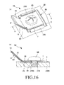
- Fig. 16(A) is a perspective view of the temporary screw holding device shown in Fig. 12 which shows a state that the screw is tightened into a threaded hole of the target object and Fig. 16(B) is a cross-sectional view thereof along line A-A in Fig. 16(A)
- Fig. 17 is a cross-sectional view of a modification of the temporary screw holding device shown in Fig. 12 .
- Fig. 18 is a perspective view of a temporary screw holding device according to a fourth embodiment of the present invention.
- Fig. 19 is a cross-sectional view of the temporary screw holding device shown in Fig. 18 which shows a state that the screw is tightened into a threaded hole of the target object.
- a fixing device 1 shown in Fig. 1 is used to fix an object 300 to be fixed (hereinafter just referred to as "object 300") to the upper surface (one surface) of a plate-shaped target object 200 provided with an opening 210.
- the opening 210 has a rectangular shape with its longitudinal direction running parallel to the Y-axis direction.
- the shape of the opening 210 is not particularly limited thereto.
- One fixing device 1 is attached to the object 300 in the present embodiment.
- a plurality of fixing devices 1 may be attached to the object 300 in different positions depending on the size, shape and weight of the object 300.
- the object 300 is not particularly limited and may be, e.g., electronic parts such as an AM/FM tuner, an AM/FM amplifier, a power supply unit and a motor.
- the target object 200 to which the object 300 is to be fixed is not particularly limited and may be, e.g., a vehicle body or a building wall (such as an inner wall, an outer wall, a ceiling or a floor).
- the object 300 used in the present embodiment includes a housing 310 for holding major components of an electronic part therein and a base 320 for supporting the housing 310.
- the housing 310 and the base 320 are made of, e.g., metallic materials such as aluminum and copper or various kinds of resin materials such as polyethylene, polypropylene, polyvinylchloride, polystyrene, polyamide and polyimide.
- the fixing device 1 includes a plate-shaped fixing member 2 fixedly provided in the object 300, a fastening member 3 engageable with the fixing member 2 and movable in the Z-axis direction with respect to the fixing member 2, a screw 4 for displacing the fastening member 3 in the Z-axis direction with respect to the fixing member 2, and a displacement preventing member (displacement preventing means) 5 for preventing the screw 4 from being displaced in the Z-axis direction.
- the fixing member 2 is integrally formed with the base 320 of the object 300.
- the base 320 partially protrudes from the housing 310 to make up the fixing member 2.
- the fixing member 2 may be formed independently of the base 320 as long as it can be attached to the object 300, and may be attached to the object 300 by bonding, welding, thread-coupling or fitting.
- the constituent material of the fixing member 2 may be, but is not particularly limited to, relatively hard materials, e.g., metallic materials such as aluminum and copper or various kinds of resin materials such as polyethylene, polypropylene, polyvinylchloride, polystyrene, polyamide and polyimide.
- the fixing member 2 is formed into a thin plate shape and the major surfaces thereof (a pair of surfaces of the fixing member 2 opposing to each other in the thickness direction) are arranged parallel to the X-Y plane.
- a through-hole 21 is formed in the fixing member 2.
- the through-hole 21 is a hole through which the shaft of the screw 4 passes. As the screw 4 is inserted through the through-hole 21, the fixing member 2 holds the screw 4 in place.
- the screw 4 is not threadedly coupled to the fixing member 2 when held in place by the fixing member 2 and is rotatable (can idle) with respect to the fixing member 2.
- the shape and size of the through-hole 21 is not particularly limited insofar as the afore-mentioned conditions are satisfied.
- the through-hole 21 may be formed into a circular shape to have a diameter greater than the largest outer diameter of the shaft of the screw 4 (namely, the outer diameter of the apexes of the thread ridges of the screw 4) but smaller than the outer diameter of the head of the screw 4.
- the fixing member 2 has a pair of cutout portions 22 and 23 arranged in a mutually opposing relationship in the Y-axis direction with the through-hole 21 interposed therebetween.
- the cutout portions 22 and 23 are formed so that they can be opened laterally outwards from the fixing member 2.
- each of the cutout portions 22 and 23 has a rectangular shape with its longitudinal direction running parallel to the X-axis direction.
- the cutout portions 22 and 23 are identical in shape with each other.
- the fastening member 3 engages with the fixing member 2 so that it can be displaced in the Z-axis direction.
- the fastening member 3 is inserted into the opening 210 of the target object 200 and serves to fasten the fixing member 2 onto the target object 200.
- the fastening member 3 includes a pair of leg portions 31 and 32, a pair of shoulder portions (drop preventing means) 38 and 39 connected to the upper ends of the leg portions 31 and 32, respectively, a connecting portion 33 for interconnecting the lower ends of the leg portions 31 and 32, and four projecting portions 34, 35, 36 and 37 provided at the opposite ends of the connecting portion 33.
- the leg portions 31 and 32 are arranged in a mutually opposing relationship in the Y-axis direction with the fixing member 2 (the through-hole 21) interposed therebetween.
- the leg portions 31 and 32 are formed into a thin plate shape to extend in the Z-axis direction and the major surfaces thereof (a pair of surfaces of each of the leg portions 31 and 32 opposing to each other in the thickness direction) are arranged parallel to the X-Z plane.
- the leg portion 31 is inserted into the cutout portion 22 of the fixing member 2, and the leg portion 32 is inserted into the cutout portion 23.
- the leg portions 31 and 32 are slidable within the cutout portions 22 and 23 with respect to the fixing member 2.
- the width (the X-axis length) W1 of the leg portion 31 is set a little smaller than the width (the X-axis length) W2 of the cutout portion 22.
- the width (the X-axis length) W3 of the leg portion 32 is set a little smaller than the width (the X-axis length) W4 of the cutout portion 23.
- the spaced-apart distance D1 between the leg portions 31 and 32 is greater than the spaced-apart distance D2 between the cutout portions 22 and 23 but smaller than the width (the Y-axis length) D3 of the fixing member 2.
- leg portions 31 and 32 By designing the leg portions 31 and 32 in this manner, it is possible to prevent the fastening member 3 from falling off from the cutout portions 22 and 23 and to prevent the leg portions 31 and 32 from making excessive contact with the fixing member 2, which makes it possible to reduce the sliding resistance caused by the contact of the leg portions 31 and 32 with the fixing member 2. This enables the leg portions 31 and 32 (namely, the fastening member 3) to smoothly slide with respect to the fixing member 2.
- the spaced-apart distance D1 between the leg portions 31 and 32 is set smaller than the length (the Y-axis length) of the opening 210.
- the connecting portion 33 is provided to interconnect the lower ends of the leg portions 31 and 32 (the insertion direction tip ends of the fastening member 3).
- the connecting portion 33 includes a threaded portion 331 positioned in the tip end of the fastening member 3 (the insertion direction tip end of the opening 210), a first tapered portion 332 for interconnecting the threaded portion 331 and the leg portion 31, and a second tapered portion 333 for interconnecting the threaded portion 331 and the leg portion 32.
- the threaded portion 331 is formed into a thin plate shape and the major surfaces thereof (a pair of surfaces of the threaded portion 331 opposing to each other in the thickness direction) are arranged parallel to the X-Y plane.
- the Y-axis length of the threaded portion 331 is smaller than the spaced-apart distance D1 between the leg portions 31 and 32. When seen in the X-Y plane, the threaded portion 331 is positioned between the leg portions 31 and 32.
- the plan-view shape of the threaded portion 331 is not particularly limited as long as the threaded portion 331 can pass through the opening 210 of the target object 200.
- the long side and short side of the threaded portion 331 are shorter than the long side and short side of the opening 210.
- the threaded portion 331 is formed into a generally rectangular shape to extend in the Y-axis direction.
- a threaded hole 331a thicker than other areas of the threaded portion 331 is formed in the central area of the threaded portion 331 by, e.g., burring.
- a female thread threadedly engaging with the screw 4 is formed on the inner surface of the threaded hole 331a.
- the screw 4 is threadedly coupled to the threaded hole 331a. If the screw 4 is rotated in one direction, the fastening member 3 is displaced to cause the threaded portion 331 to move toward the fixing member 2. If the screw 4 is rotated in the other direction, the fastening member 3 is displaced to cause the threaded portion 331 to move away from the fixing member 2.
- the first tapered portion 332 is formed into a thin plate shape and the major surfaces thereof (a pair of surfaces of the first tapered portion 332 opposing to each other in the thickness direction) are arranged in a slanting relationship with the X-Y plane and the X-Z plane.
- the second tapered portion 333 is formed into a thin plate shape and the major surfaces thereof (a pair of surfaces of the tapered portion 333 opposing to each other in the thickness direction) are arranged in a slanting relationship with the X-Y plane and the X-Z plane.
- the spaced-apart distance D4 between the first and second tapered portions 332 and 333 is gradually decreased from the threaded portion 331 toward the leg portions 31 and 32.
- the connecting portion 33 makes up a taper portion in which the tip end extension of the fastening member 3 tapers off. Provision of the connecting portion 33 of this shape makes it easy to guide the tip end portion of the fastening member 3 into the opening 210 and makes it possible to smoothly insert the fastening member 3 into the opening 210.
- the first tapered portion 332 is formed into a generally trapezoidal shape so that the width (the X-axis length) W5 thereof can be gradually increased from the threaded portion 331 toward the leg portion 31.
- the width of the upper end of the first tapered portion 332 (the end of the first tapered portion 332 near the leg portion 31) is greater than the width of the leg portion 31.
- the first tapered portion 332 is connected to the leg portion 31 in the central portion of the upper end thereof excluding the lateral edge portions.
- the shape of the second tapered portion 333 is the same as the shape of the first tapered portion 332 and therefore will not be described in detail.
- a pair of projecting portions 34 and 35 are respectively provided at the upper end portion of the first tapered portion 332, namely at one end portion of the connecting portion 33.
- the projecting portions 34 and 35 are positioned at the opposite sides with respect to the leg portion 31, that is at the lateral edge portions thereof.
- each of the projecting portions 34 and 35 projects laterally outward from the fastening member 3 and toward the fixing member 2 (In other words, the projecting portions 34 and 35 project obliquely leftwards and upwards in Fig. 2 ).
- each of the projecting portions 34 and 35 is formed on the same plane as the first tapered portion 332.
- the projecting portions 34 and 35 are formed into a generally triangular shape so that the width thereof can be gradually decreased toward the tip end thereof.
- the corner making up the tip end portion is positioned at the outermost side in the Y-axis direction.
- the spaced-apart distance D5 between the tip ends of the projecting portions 34 and 35 is greater than the width W2 of the cutout portion 22 formed in the fixing member 2.
- a pair of projecting portions 36 and 37 are respectively provided at the upper end portion of the second tapered portion 333, namely at the other end portion of the connecting portion 33.
- the projecting portions 36 and 37 have the same configuration as that of the projecting portions 34 and 35 and therefore will not be described in detail.
- the spaced-apart distance D6 between the tip ends of the projecting portions 34 and 36 spaced apart in the Y-axis direction is set a little greater than the Y-axis length of the opening 210. This holds true in case of the spaced-apart distance between the tip ends of the projecting portions 35 and 37. This ensures that, when the fastening member 3 is displaced toward the fixing member 2 with the fastening member 3 being inserted into the opening 210, the four projecting portions 34, 35, 36 and 37 come into abutment with the lower surface of the target object 200 in a reliable manner.
- the projecting portions 34 and 36 make abutment with the lower surface of the target object 200 at the opposite sides with respect to the opening 210 (This holds true in case of the projecting portions 35 and 37). This makes it possible to fix the object 300 onto the target object 200 in a reliable manner.
- a shoulder portion 38 is provided in the upper end portion of the leg portion 31 (in the end portion of the leg portion 31 opposite to the fastening member 3).
- a shoulder portion 39 is provided in the upper end portion of the leg portion 32.
- the shoulder portions 38 and 39 have a function of keeping the fastening member 3 engaged with the fixing member 2, namely a function of preventing any falling of the fastening member 3 from the fixing member 2, when the thread-coupling of the threaded hole 331a and the screw 4 is released inadvertently or when the screw 4 is not attached in the manufacturing process of the fixing device 1.
- each of the shoulder portions 38 and 39 is formed into a thin plate shape and the major surfaces thereof (a pair of surfaces of each of the shoulder portions 38 and 39 opposing to each other in the thickness direction) are arranged parallel to the X-Z plane.
- the width (the X-axis length) W6 of the shoulder portion 38 is set greater than the width W2 of the cutout portion 22.
- the width (the X-axis length) W7 of the shoulder portion 39 is set greater than the width W4 of the cutout portion 23.
- the leg portions 31 and 32, the connecting portion 33, the projecting portions 34, 35, 36 and 37, the shoulder portions 38 and 39, which make up the fastening member 3, have been described above in detail. These components can be formed in one piece by, e.g., machining a single thin plate member into a desired outward shape and then bending the plate at specified points. This makes it possible to manufacture the fastening member 3 in a simple manner.
- the constituent material of the fastening member 3 is not particularly limited but may preferably be a relatively hard material.
- metallic materials such as aluminum and copper can be used as the constituent material of the fastening member 3.
- the screw 4 is not threadedly coupled to but rotatably inserted through the through-hole 21 of the fixing member 2.
- the screw 4 is threadedly coupled to the threaded hole 331a formed in the threaded portion 331 of the fastening member 3.
- the length of the screw 4 is set such that the thread coupling of the screw 4 to the threaded hole 331a is not released when the threaded portion 331 of the fastening member 3 is moved farthest away from the fixing member 2, namely when the shoulder portions 38 and 39 are brought into abutment with the fixing member 2.
- the screw 4 and the fastening member 3 may be displaced together in the Z-axis direction with respect to the fixing member 2. If such displacement occurs, it may be hard to insert the fastening member 3 into the opening 210.
- a displacement preventing means 5 is attached to the screw 4 in the fixing device 1 of the present embodiment.
- the displacement preventing means 5 is formed of a clamp member that can be secured around the shaft of the screw 4, e.g., an E-ring.
- the displacement preventing means 5 is fixed to the base end portion of the shaft of the screw 4 with the fixing member 2 interposed between the displacement preventing means 5 and the head of the screw 4.
- the screw 4 cannot be displaced in the Z-axis direction, thereby restraining free displacement of the fastening member 3 in the Z-axis direction.
- the fastening member 3 cannot be displaced in the Z-axis direction with respect to the fixing member 2.
- Use of this configuration makes it possible to easily insert the fastening member 3 into the opening 210.
- the configuration of the fixing device 1 has been described above in detail. Next, a method of using the fixing device 1 will be described with reference to Figs. 6 and 7 .
- the screw 4 is rotated so that the threaded portion 331 of the fastening member 3 can be moved farthest away from the fixing member 2 as shown in Fig. 6A , namely so that the shoulder portions 38 and 39 can be brought into abutment with the upper surface of the fixing member 2.
- the fastening member 3 is inserted into the opening 210 of the target object 200 to place the projecting portions 34, 35, 36 and 37 below the lower surface of the target object 200 as shown in Fig. 6B .
- the projecting portions 34, 35, 36 and 37 are brought into abutment with the side surface of the opening 210 and are flexed inwards.
- the projecting portions 34, 35, 36 and 37 are quickly returned to the original state (the state available before passing through the opening 210).
- the screw 4 is rotated in the reverse direction to displace the threaded portion 331 of the fastening member 3 toward the fixing member 2.
- the fixing member 2 is fastened to the target object 200 by the projecting portions 34, 35, 36 and 37, and the object 300 is fixed onto the target object 200.
- the screw 4 may be further rotated to cause the threaded portion 331 to move nearer to the fixing member 2.
- the projecting portions 34, 35, 36 and 37 may cut into the target object 200 as shown in Fig. 7B or may be deformed as shown in Fig. 7C . This makes it possible to more securely fix the object 300 onto the target object 200.
- the first embodiment has been described above. Description will now be made on a modified example of the first embodiment.
- the base 320 of the object 300 is formed into an elongate shape so that the opposite end portions thereof can protrude from the housing 310.
- One end portion of the base 320 makes up the fixing member 2 of the fixing device 1 described above.
- the other end portion of the base 320 makes up a deformable portion 321 that can be bent or flexed in the thickness direction of the base 320.
- the tip end portion 321a of the deformable portion 321 is arranged so that the major surfaces thereof can extend parallel to the X-Y plane.
- An elastic body 322 made of rubber or other like materials is provided on the upper surface of the tip end portion 321a. In this deformable portion 321, the Z-axis spaced-apart distance D8 between the upper surface of the elastic body 322 and the central portion 323 of the base 320 is set a little smaller than the thickness of the target object 200.
- an opening 220 for insertion of the deformable portion 321 is formed in the target object 200.
- the object 300 is fixed to the target object 200 in the following manner.
- the deformable portion 321 is first inserted into the opening 220 with the object 300 kept inclined with respect to the target object 200. Then, as shown in Fig. 9B , the fastening member 3 of the fixing device 1 is inserted into the opening 210. Thereafter, the object 300 is fixed onto the target object 200 by tightening the fixing device 1 in the manner described above. In this state, the elastic body 322 provided in the deformable portion 321 is compressed in the thickness direction and the deformable portion 321 is flexed in the thickness direction. Thus, there is generated a force biasing the elastic body 322 and the deformable portion 321 into a natural state (namely, a reaction force). The object 300 is more strongly fixed onto the target object 200 by the reaction force.
- Fig. 10 is a cross-sectional view of a fixing device for fixing an object onto a target object with a screw according to a second embodiment of the present invention.
- Fig. 11 is a cross-sectional view of the fixing device shown in Fig. 10 which shows a state that the fixing member is fixed onto the target object by the fixing device shown in Fig. 10 .
- the fixing device 1A of the present embodiment is the same as the fixing device 1 of the first embodiment except that the fastening member 3A is fixed to the fixing member 2 and that the leg portions 31A and 32B of the fastening member 3A are deformable.
- the same components as those of the first embodiment will be designated by like reference symbols.
- the fastening member 3A of the fixing device 1A is fixed to the fixing member 2.
- the method of fixing the fastening member 3A to the fixing member 2 is not particularly limited.
- the shoulder portions 38 and 39 and the fixing member 2 may be welded together or may be bonded together through the use of an adhesive agent.
- Each of the leg portions 31A and 32B is formed into an inwardly-bent generally wedge shape.
- the bend portion of each of the leg portions 31A and 32B is weaker than the remaining portions thereof.
- Each of the leg portions 31A and 32B is readily deformable because it can be collapsed around the bend portion.
- the screw 4 is rotated to cause the threaded portion 331 of the fastening member 3A to move toward the fixing member 2
- the threaded portion 331 is moved toward the fixing member 2 along with the flexural deformation of the leg portions 31A and 32B around the bend portions thereof as shown in Fig. 11 . Consequently, the lower surface of the fixing member 2 comes into abutment with the upper surface of the target object 200, and the four projecting portions 34, 35, 36 and 37 make contact with the lower surface of the target object 200.
- the object 300 is fixed onto the target object 200.
- the object of the prevent invention is also achieved by a temporary screw holding device described below.
- the present invention is directed to a temporary screw holding device 3B to be attached to a fixing member 2B to be fixed onto a target object 200B with a screw 4B, the fixing member 2B being provided with an object to be fixed 300B.
- the target object 200B has a threaded hole 230B to which the screw 4B is to be threaded.
- the temporary screw holding device 3B comprises a plate-shaped support portion 6 which is to be placed on the fixing member 2B, the support portion 6 having a hole 61 in which the screw 4B passes; a screw holding portion 7 having a screw insertion hole 71 for holding the screw 4B, the screw holding portion 7 being provided above the support portion 6 with a space therebetween; and a coupling portion 8 which couples one side of the support portion 6 and a corresponding side of the screw holding portion 7, the coupling portion 8 having a bend portion 81 which is bendable or deformable toward an outside direction at a region between the support portion 6 and the screw holding portion 7.
- the coupling portion 8 is configured so that the bend portion 8 of the coupling portion 81 is deformed to protrude toward the outside direction as the screw holding portion 7 approaches the support portion 6 by fastening the screw 4B into the threaded hole 230B of the target object 200B.
- the temporary screw holding device 3B further comprises a falling preventing means 9 for preventing the screw 4B from being fallen off from the screw insertion hole 71.
- the falling preventing means 9 includes at least one projection 91, 92, 93, 94 projecting from an edge of the screw insertion hole 71 toward a center thereof so that the at least one projection engages with a screw groove of the screw 4B.
- the bend portion 81 of the coupling portion 8 is in advance bent so as to form a wedge shape part.
- a length L1 from a tip of the wedge shape bend portion 81 of the coupling portion 8 to the screw holding portion 7 is shorter than a length L2 from the tip of the wedge shape bend portion 81 of the coupling portion 8 to the support portion 6.
- the fixing member 2B has a slide holder 22B, 23B provided on an upper surface thereof, and the temporary screw holding device 3B is adapted to be attached to the fixing member 2B by inserting the support portion 6 into the slide holder 22B, 23B.
- the support portion 6 has an edge part from which the support portion 6 is inserted into the slide holder 22B, 23B, and the edge part of the support portion 6 is tapered.
- the temporary screw holding device 3B further comprises a positioning means 10 for positioning the support portion 6 with respect to the fixing member 2B when the temporary screw holding device 3B is attached to the fixing member 2B.
- the positioning means 10 includes an engagement portion 63 formed in the support portion 6, and the support portion 6 is positioned with respect to the fixing member 2B in such a manner that the engagement portion 63 is engaged with a protrusion 24B formed on the fixing member 2B.
- Fig. 12 is a perspective view of a temporary screw holding device according to the third embodiment of the present invention, which shows a state that the temporary screw holding device is attached to the fixing member.
- Fig. 13(A) is a perspective view of the fixing member shown in Fig. 12 and Fig. 13(B) is a cross-sectional view thereof along line A-A in Fig. 13(A) .
- Fig. 14 is a perspective view of the temporary screw holding device shown in Fig. 12 .
- Fig. 15 is a cross-sectional view of the temporary screw holding device shown in Fig. 12 .
- Fig. 16(A) is a perspective view of the temporary screw holding device shown in Fig.
- Fig. 16(B) is a cross-sectional view thereof along A-A line in Fig. 16(A) .
- Fig. 17 is a cross-sectional view of a modification of the temporary screw holding device shown in Fig. 12 .
- the upper side in Fig 16(B) will be referred to as "upper” and the lower side thereof will be referred to as "lower” for convenience of explanation.
- the temporary screw holding device 3B is attached, when in use, to the fixing member 2B to be screw-fixed to the target object 200B.
- the temporary screw holding device 3B is used to temporarily fix a screw (including a bolt or other threaded members) 4B to the fixing member 2B.
- this temporary screw holding device 3B it is possible to keep the screw 4B held by the fixing member 2B, namely to prevent the screw 4B from dropping from the fixing member 2B even when the screw 4B is not held by the hands of a worker.
- the worker keeps the fixing member 2B being provided with the object 300B in a specified position of the target object 200B with one hand and tightens the screw 4B into a threaded hole 230B (see Fig. 16B ) of the target object 200B with a tool such as a screwdriver held by the other hand.
- the temporary screw holding device 3B is readily deformed when tightening the screw 4B and does not hinder the screw-fixing operation using the screw 4B.
- the object 300B of the present embodiment includes a housing 310B for holding major components of an electronic part therein, and a base 320B for supporting the housing 310B.
- the fixing member 2B is integrally formed with the base 320B of the object 300B.
- the base 320B partially protrudes from the housing 310B to make up the fixing member 2B.
- the fixing member 2B may be formed independently of the base 320B as long as it can be attached to the object 300B, and may be attached to the object 300B by bonding, welding, thread-coupling or fitting.
- At least one through-hole 21B for insertion of the screw 4B serving as a screw-fixing hole is formed in the fixing member 2B.
- the number and arrangement of the through-hole 21B is not particularly limited insofar as the fixing member 2B can be screw-fixed to a specified position of the target object 200B through the through-hole 21B.
- a plurality of through-holes 21B may be formed depending on the shape, size and weight of the fixing member 2B.
- the shape and size of the through-hole 21B is not particularly limited insofar as the screw 4B can pass through the through-hole 21B. It is preferred that the through-hole 21B be formed into a circular shape to have a diameter slightly greater than the outer diameter of the shaft of the screw 4B (namely, the outer diameter of the apexes of the thread ridges of the screw 4B or the largest diameter of the screw 4B). This makes it possible to smoothly insert the screw 4B into the through-hole 21B. This also makes it difficult for a gap to be formed between the shaft of the screw 4B and the fixing member 2B. Thus, it is possible to prevent deviation of the fixing member 2B from the specified position, which would otherwise be caused by the gap.
- a slide holder including a pair of slide pieces 22B and 23B which extend in the same direction and are arranged in a mutually opposing relationship with the through-hole 21B interposed therebetween.
- the temporary screw holding device 3B has a support portion 6 to be inserted into the slide holder 22B and 23B.
- the support portion 6 is attached to the fixing member 2B by sliding the support portion 6 along the surface of the fixing member 2B so that the support portion 6 can be inserted into and engaged with the slide holder 22B and 23B.
- Each of the slide holder pieces 22B and 23B can be formed by forming a generally C-like cutout portion in the fixing member 2B and bending the cutout portion into a desired shape. With this method, the slide holder 22B and 23B can be integrally formed with the fixing member 2B, which makes it easy to form the slide holder 22B and 23B.
- a protrusion 24B is formed in the vicinity of the through-hole 21B.
- the protrusion 24B is engageable with an engagement portion 63 formed in the support portion 6 of the temporary screw holding device 3B.
- the protrusion 24B decides the position of the support portion 6 with respect to the fixing member 2B by engaging with the engagement portion 63.
- the protrusion 24B and the engagement portion 63 constitute a positioning means 10 for deciding the position of the support portion 6 with respect to the fixing member 2B.
- the protrusion 24B is not particularly limited in its shape but may preferably have a shape with a slanting surface, e.g., a hemispherical shape. This enables the insertion direction tip end of the support portion 6 to easily climb over the protrusion 24B when the support portion 6 is slid into the slide holder 22B and 23B. Therefore, the protrusion 24B can smoothly engage with the engagement portion 63. It is preferred that the height of the protrusion 24B be smaller than the thickness of the support portion 6.
- the protrusion 24B be positioned ahead of the through-hole 21B in the direction in which the support portion 6 is inserted into the slide holder 22B and 23B. This makes it possible to prevent the protrusion 24B from hindering the insertion of the support portion 6 into the slide holder 22B and 23B and to eliminate the need to apply an excessive force when the support portion 6 is inserted into the slide holder 22B and 23B.
- the temporary screw holding device 3B includes the support portion 6 to be attached to the fixing member 2B, a screw holding portion 7 for holding the screw 4B used in screw fixation and a coupling portion 8 for interconnecting the support portion 6 and the screw holding portion 7.
- the temporary screw holding device 3B further includes a falling preventing means 9 for preventing falling of the screw 4B held by the screw holding portion 7.
- the support portion 6, the screw holding portion 7 and the coupling portion 8 are integrally formed by, e.g., machining a thin plate member into a desired shape and bending the plate member at specified points.
- the constituent material of the support portion 6, the screw holding portion 7 and the coupling portion 8 may be, but is not particularly limited to, e.g., metallic materials such as aluminum and copper or various kinds of resin materials such as polyethylene, polypropylene, polyvinylchloride, polystyrene, polyamide and polyimide.
- the support portion 6 is attached to the fixing member 2B by inserting the same into the slide holder 22B and 23B of the fixing member 2B in the manner mentioned above.
- the support portion 6 is formed into a thin plate shape. When seen in a plan view, the support portion 6 has a rectangular shape (a generally square shape).
- the plan-view shape of the support portion 6 is not particularly limited but may be a circular shape, a triangular shape, a pentagonal shape or other polygonal shapes.
- the thickness of the support portion 6 may preferably be, but is not limited to, about 0.3 mm to 0.6 mm. This makes it possible to reduce the thickness of the support portion 6 while securing the mechanical strength of the support portion 6. Accordingly, it is possible to reduce the size of the temporary screw holding device 3B.
- a through-hole 61 for insertion of the screw 4B is formed in the central area of the support portion 6.
- the through-hole 61 is positioned so that it can overlap with the through-hole 21B of the fixing member 2B when the position of the support portion 6 is decided with respect to the fixing member 2B by means of the positioning means 10.
- the shape and size of the through-hole 61 is not particularly limited insofar as the shaft of the screw 4B can pass through the through-hole 61. It is preferred that the through-hole 61 be formed into a circular shape having a diameter slightly greater than the outer diameter of the shaft of the screw 4B. This enables the screw 4B to smoothly pass through the through-hole 61. This also makes it difficult for a gap to be formed between the shaft of the screw 4B and the support portion 6, thereby making it possible to strongly screw-fix the fixing member 2B onto the target object 200B.
- the support portion 6 is inserted into the slide holder 22B and 23B at the opposite side from the coupling portion 8.
- the tip end portion 62 positioned at the insertion direction tip end of the support portion 6 is formed into such a shape that the thickness thereof is gradually decreased toward the tip end (edge part), more specifically such a shape that the upper surface of the support portion 6 (the surface of the support portion 6 facing the screw holding portion 7) is tapered.
- the positioning means 10 for deciding the position of the support portion 6 with respect to the fixing member 2B is provided in the support portion 6. This makes it possible to reliably position the temporary screw holding device 3B in a specified position on the fixing member 2B and to maintain such state.
- the positioning means 10 includes the engagement portion 63 formed in the support portion 6. As shown in Fig. 15 , the positioning means 10 decides the position of the support portion 6 with respect to the fixing member 2B by bringing the engagement portion 63 into engagement with the protrusion 24B of the fixing member 2B in a state that the support portion 6 is inserted into the slide holder 22B and 23B. As mentioned above, the hole 61 overlaps with the through-hole 21B when the position of the support portion 6 is decided with respect to the fixing member 2B by means of the positioning means 10.
- the positioning means 10 may include a recessed portion opened toward the lower surface of the support portion 6 (the surface of the support portion 6 facing the fixing member 2B) so that the recessed portion can engage with the protrusion 24B.
- the screw holding portion 7 serves to hold the screw 4B in place.
- the screw holding portion 7 is formed into a thin plate shape.
- the screw holding portion 7 is arranged in a generally-parallel opposing relationship with the support portion 6 through a space left therebetween.
- the plan-view shape of the screw holding portion 7 is not particularly limited but may preferably be such a shape that the screw holding portion 7 does not make contact with the slide holder 22B and 23B when the screw-fixing of the fixing member 2B to the target object 200B is completed as shown in Fig. 16 (namely, when the screw 4B is tightened).
- the screw holding portion 7 is formed to have a generally rectangular plan-view shape so that the screw holding portion 7 does not make contact with the slide holder 22B and 23B when the screw-fixing of the fixing member 2B to the target object 200B is completed.
- the plan-view shape of the screw holding portion 7 is not limited to the rectangular shape but may be a circular shape, a triangular shape, a pentagonal shape or other polygonal shapes.
- the thickness of the screw holding portion 7 may preferably be, but is not limited to, about 0.3 mm to 0.6 mm. This makes it possible to reduce the thickness of the screw holding portion 7 while securing the mechanical strength of the screw holding portion 7. Accordingly, it is possible to further reduce the size of the temporary screw holding device 3B.
- a through-hole 71 for insertion of the screw 4B is formed in the central area of the screw holding portion 7.
- the through-hole 71 is formed into a circular shape to have a diameter slightly greater than the outer diameter of the shaft of the screw 4B but smaller than the outer diameter of the head of the screw 4B.
- the screw holding portion 7 holds the screw 4B in place in a state that the shaft of the screw 4B is inserted through the through-hole 71. With this configuration, the screw 4B is held in place upon merely inserting the screw 4B through the through-hole 71. This helps simplify the work of holding the screw 4B in the screw holding portion 7.
- the spaced-apart distance between the screw holding portion 7 and the support portion 6 is not particularly limited and can be properly set depending on the length of the shaft of the screw 4B to be held in the screw holding portion 7.
- the spaced-apart distance between the screw holding portion 7 and the support portion 6 is set a little shorter than the length of the shaft of the screw B. This makes it possible to keep the tip end portion of the shaft of the screw 4B passing through the through-holes 61 and 21B when the screw 4B is held by the screw holding portion 7 as shown in Fig. 15 . Accordingly, it is possible to further enhance the efficiency of the screw-fixing work.
- the falling preventing means 9 for preventing falling of the screw 4B from the screw holding portion 7 is provided in the screw holding portion 7. Provision of such falling preventing means 9 makes it possible to prevent any inadvertent falling of the screw 4B from the screw holding portion 7, thereby further enhancing the work efficiency.
- the falling preventing means 9 includes four protrusions 91, 92, 93 and 94 protruding from the side surface (edge part) of the through-hole 71 toward the center thereof.
- the protrusions 91, 92, 93 and 94 are arranged along the circumferential direction of the through-hole 71 at a regular interval.
- the protrusions 91, 92, 93 and 94 are integrally formed with the screw holding portion 7.
- the number of the protrusions 91, 92, 93 and 94 is not limited to four as in the present embodiment but may be one through three or five or more. In case of providing a plurality of protrusions, they may be arranged along the circumferential direction of the through-hole 71 at a regular interval.
- the protrusions 91, 92, 93 and 94 get into the thread grooves of the screw 4B (the valleys between the adjoining thread ridges), thereby preventing the screw 4B from just falling off from the through-hole 71. It is preferred that the tip ends of the protrusions 91, 92, 93 and 94 be positioned between the bottoms of the thread grooves and the apexes of the thread ridges when the shaft of the screw 4B is aligned with the center axis of the through-hole 71. In other words, it is preferred that the protrusions 91, 92, 93 and 94B do not make contact with the bottoms of the thread grooves. This means that the screw 4B and the protrusions 91, 92, 93 and 94 do not come into full thread coupling, which makes it possible to easily insert the screw 4B into the through-hole 71.
- the coupling portion 8 interconnects the support portion 6 and the screw holding portion 7.
- the screw holding portion 7 is cantilevered to the support portion 6 through the coupling portion 8. More specifically, the coupling portion 8 of the present embodiment is formed to interconnect one side of the support portion 6 and a corresponding side of the screw holding portion 7. With the configuration in which the screw holding portion 7 is cantilevered to the support portion 6 through the coupling portion 8, it is possible to further reduce the size of the temporary screw holding device 3B.
- the coupling portion 8 is bent outwards from the space (region) S between the support portion 6 and the screw holding portion 7 and is formed into a generally wedge shape.
- the coupling portion 8 having such a shape is easily deformable. If the screw 4B is tightened to cause the screw holding portion 7 to move toward the support portion 6, the coupling portion 8 is collapsed and deformed so that it can protrude outwards from the space S. Since the coupling portion 8 is easily deformable as mentioned above, it is possible to perform the screw-fixing work of the fixing member 2B to the target object 200B easily.
- the screw holding portion 7 is pressed by the head of the screw 4B and moved toward the support portion 6.
- the screw holding portion 7 makes contact with the support portion 6 as shown in Fig. 16 .
- the coupling portion 8 is deformed by the displacement of the screw holding portion 7 so that it can be double-folded in the bend portion 81, namely so that the first extension portion 82 extending from the bend portion 81 to the screw holding portion 7 can overlap with the second extension portion 83 extending from the bend portion 81 to the support portion 6.
- the coupling portion 8 is formed into such a shape that it can remain bent outwards from the space S in a natural state. Therefore, if the screw holding portion 7 is displaced by tightening the screw 4B, the coupling portion 8 is reliably deformed to protrude outwards from the space S. Since nothing exists between the screw holding portion 7 and the support portion 6, it is possible to bring the screw holding portion 7 into contact (surface-to-surface contact) with the support portion 6 by tightening the screw 4B. As a result, it is possible to screw-fix the fixing member 2B to the target object 200B with a strong tightening force as compared with the prior art example in which a gap is left between the screw holding portion 7 and the support portion 6.
- the inclination of the first extension portion 82 and the second extension portion 83 with respect to the plane parallel to the support portion 6 and the screw holding portion 7 is not particularly limited but may be preferably about 30° to 70°, more preferably about 40° to 50° and even more preferably about 45°. If the angles ⁇ 1 and ⁇ 2 are smaller than the lower limit values noted above, it is sometimes the case that, depending on the strength and size (length) of the coupling portion 8, bending occurs in other portions than the bend portion 81 or double-folded deformation of the coupling portion 8 does not occur in the tidy manner mentioned above.
- angles ⁇ 1 and ⁇ 2 are greater than the upper limit values noted above, it is likely that, depending on the length of the coupling portion 8 (the spaced-apart distance between the screw holding portion 7 and the support portion 6), the coupling portion 8 may excessively protrude outwards from the space S, consequently increasing the size of the temporary screw holding device 3B.
- the angles ⁇ 1 and ⁇ 2 fall within the numerical value ranges noted above, it is possible to reliably deform the coupling portion 8 into a desired shape while restraining any increase in the size of the temporary screw holding device 3B.
- the coupling portion 8 of the present embodiment is inclined with respect to the major surfaces of the support portion 6 so that, when the screw-fixing work comes to an end, the bend portion 81 can be positioned above the opposite end portions of the coupling portion 8 (namely, the end portion 84 connected to the screw holding portion 7 and the end portion 85 connected to the support portion 6).
- the coupling portion 8 By allowing the coupling portion 8 to be deformed in this manner, it is possible to prevent the coupling portion 8 from making contact with the fixing member 2B during deformation.
- the coupling portion 8 may make contact with the fixing member 2B, thereby restraining movement of the screw holding portion 7, hindering a smooth screw-fixing work and unwillingly breaking the coupling portion 8.
- the coupling portion 8 is deformed in the manner described above.
- the shape of the coupling portion 8 is designed as follows.
- the length L1 of the first extension portion 82 extending from the bend portion (a tip of the wedge shape bend portion) 81 to the screw holding portion 7 is set shorter than the length L2 of the second extension portion 83 extending from the bend portion (a tip of the wedge shape bend portion) 81 to the support portion 6.
- the difference between L1 and L2 is not particularly limited but may preferably be equal to, e.g., the thickness of the support portion 6.
- the end portion 84 of the first extension portion 82 connected to the screw holding portion 7 is deviated toward the space S (to the right in Fig. 15 ) from the end portion 85 of the second extension portion 83 connected to the support portion 6.
- the coupling portion 15 is not particularly limited but may preferably be equal to, e.g., the thickness of the coupling portion 8.
- first and second design items are all employed in the present embodiment, the same effects as mentioned above can be attained by employing only one of the first and second design items.
- the temporary screw holding device 3B of the third embodiment has been described above, it is possible to distribute the temporary screw holding device 3B as a screw-fixing member assembly in which the temporary screw holding device 3B is attached to the fixing member 2B with the screw 4B held in the temporary screw holding device 3B. This makes it possible to directly attach the object 300B to a target object 200B at a manufacturing site such as a factory or the like.
- Fig. 18 is a perspective view of a temporary screw holding device according to the fourth embodiment of the present invention.
- Fig. 19 is a cross-sectional view of the temporary screw holding device shown in Fig. 18 which shows a state that the screw is tightened into a threaded hole of the target object.
- the temporary screw holding device 3C of the present embodiment is the same as the temporary screw holding device 3B of the third embodiment except the shape and physical properties of the coupling portion 8C.
- the same components as those of the third embodiment will be designated by like reference symbols.
- the coupling portion 8C of the temporary screw holding device 3C is curved or bulged outwards from the space S.
- the coupling portion 8C has a radius of curvature substantially constant along the extension direction thereof.
- the coupling portion 8C is elastically deformable.
- a force biasing the coupling portion 8C into a natural state namely, a state in which the screw holding portion 7 and the support portion 6 are spaced apart from each other
- the screw holding portion 7 is pressed against the head of the screw 4B and the support portion 6 is pressed against the fixing member 2B. This makes it possible to prevent the screw 4B from being loosened over time.
- the coupling portion 8C is returned back to the natural state, thereby restoring the temporary screw holding device 3C to the original shape. This means that the temporary screw holding device 3C of the present embodiment is reusable.
- the constituent material of the coupling portion 8C is not particularly limited as long as it is elastically deformable.
- Examples of the constituent material of the coupling portion 8C include: various kinds of rubber materials (particularly, vulcanized ones) such as natural rubber, isoprene rubber, butadiene rubber, styrene-butadiene rubber, nitrile rubber, chloroprene rubber, butyl rubber, acryl rubber, ethylene-propylene rubber, hydrin rubber, urethane rubber, silicon rubber and fluoro-rubber; various kinds of thermoplastic elastomer such as styrene-based elastomer, polyolefin-based elastomer, polyvinylchloride-based elastomer, polyurethane-based elastomer, polyester-based elastomer, polyamide-based elastomer, polybutadiene-based elastomer, trans-polyisoprene-based elastomer, fluor
- the coupling portion 8C is formed independently of the screw holding portion 7 and the support portion 6 and then bonded to the screw holding portion 7 and the support portion 6 by various kinds of bonding methods such as welding and the like.
- the coupling portion of the third embodiment described above includes a single bend portion
- the number of the bend portion is not particularly limited but may be plural.
Abstract
Description
- The present invention relates to a fixing device.
- In the manufacture of, e.g., a motor vehicle, various kinds of parts (particularly, electronic parts such as an AM filter and an AM/FM amplifier) are fixed to a vehicle body by a screw holding work using screws. In general, a worker performs such a screw holding work by keeping a part in a specified position of a vehicle body with one hand and tightening a screw with a tool such as a screwdriver held by the other hand while applying a pressing force to the screw. In this method, however, both hands are not free, which makes it hard to hold the screw. As a result, a problem is posed in that the screw may be removed and dropped during the work, thereby reducing the work efficiency.
-
JP2005-504933A - The fixing clip can fix the handgrip to the vehicle body in the following manner. First, the U-shaped extension of the anchoring portion is inserted into a body hole formed in the ceiling of the vehicle body until the strip comes into contact with the ceiling. Then, a holder plate of the handgrip is embedded in the strip. A strip hole for passage of a fixing screw is formed in the strip. The fixing screw is inserted through the strip hole and threadedly coupled with the clip plate. Then, the fixing screw is rotated to cause the clip plate to come close to the holder plate. During displacement toward the holder plate, the clip plate outwardly expands an expansion flap provided in the anchoring portion. By pressing the expanded expansion flap against the ceiling area around the body hole, the clip plate securely fixes the holder plate to the ceiling.
- With the fixing clip set forth above, it is possible to easily fix a desired object member to a desired anchoring spot (member). In the fixing clip disclosed in
JP2005-504933A -
JP5-263816A - The temporary screw holding device is used in such a manner that the base thereof is fixed to a screw fixation area of a part by a double-sided tape. A worker brings the part carrying the temporary screw holding device into alignment with a specified area of a vehicle body and tightens a screw with a tool such as a screwdriver while applying a pressing force to the screw. The temporary screw holding device disclosed in
JP5-263816A - While the temporary screw holding device disclosed in
JP5-263816A - A first problem resides in that the temporary screw holding device becomes greater in size due to the configuration thereof. Since the temporary screw holding device is designed so that, when tightening the screw, the leg portions can be crushed inwards in a double folded state, it is necessary to increase the length of the base and the holder portion (namely, the length of the base and the holder portion in the direction in which the leg portions are spaced apart) and to secure a space within which the leg portions are crushed. As a result, the temporary screw holding device becomes greater in size.
- A second problem lies in that the tightening force of the screw is decreased in the temporary screw holding device. The temporary screw holding device is designed so that, when tightening the screw, the leg portions can be crushed inwards in a double folded state. In the state that the screw is tightened, therefore, the crushed leg portions exist between the holder portion and the base, thereby leaving a gap between the holder portion and the base (see
Fig. 3 inJP5-263816A - It is an object of the present invention to provide a fixing device capable of easily fixing an object onto a target object with a simple configuration.
- In order to achieve the above object, the present invention is directed to a fixing device for fixing an object onto a target object having an opening, which comprises a fixing member formed from a plate-shaped member having a through-hole, the object being provided on the fixing member; a fastening member for fixing the fixing member with the object onto the target object, the fastening member comprising a pair of leg portions which are engaged at respective one ends thereof with the fixing member, a connecting portion which connects the other ends of the leg portions together and in which a threaded hole is formed, and at least one projecting portion projecting outwardly with respect to the connecting portion toward the fixing member; and a screw which rotatably passes through the through-hole of the fixing member and is adapted to be threaded into the threaded hole of the fastening member. With the fixing device having the above structure, when the screw is rotated to be threaded into the threaded hole in a state that the fixing member is positioned on one surface of the target object and the fastening member is positioned on the other surface of the target object through the opening of the target object, the fastening member is displaced according to the rotation of the screw so that the projecting portion makes abutment with the other surface of the target object so as to hold the target object between the projecting portion of the fastening member and the fixing member, thereby fixing the object onto the target object through the fixing member.
- This makes it possible to prevent the screw from removing and dropping during the work.
- In the fixing device according to the present invention, it is preferred that the projection portion engages a part of the other surface of the target object near an edge of the opening in a state that the target object is held between the projecting portion of the fastening member and the fixing member.
- This makes it possible to prevent the fastening member from being excessively displaced toward the fixing member, which assists in improving the operability of the fixing device.
- In the fixing device according to the present invention, it is preferred that the at least one projecting portion includes two pairs of projecting portions, and each pair of projecting portions is provided at each end of the connecting portion.
- This makes it possible to fix the object to the target object in a reliable manner.
- In the fixing device according to the present invention, it is preferred that the fixing member includes a pair of cutout portions formed in the plate-shaped member at the opposite sides of the through-hole, and the pair of leg portions are slidably displaced within the cutout portions, respectively.
- This makes it possible to prevent the fastening member from being fallen off from the cutout portions.
- In the fixing device according to the present invention, it is preferred that the connecting portion includes a threaded portion in which the threaded hole is formed and a pair of tapered portions which are coupled to the leg portions and both sides of the threaded portion, respectively, wherein the tapered portions are inclined so that a distance therebetween decreases far away from the fixing member.
- This makes it possible to smoothly insert the fastening member into the opening of the target object.
- In the fixing device according to the present invention, it is preferred that the fastening member includes a pair of shoulder portions which are coupled to the one ends of the leg portions, respectively, so as to engage with the fixing member for preventing the fastening member from being fallen off from the fixing member when the screw is threaded off from the threaded hole.
- This makes it possible to keep the fastening member engaged with the fixing member when the screw is threaded off from the threaded hole.
- In the fixing device according to the present invention, it is preferred that the fastening member is formed by bending and/or folding a single metal plate member.
- This makes it possible to manufacture the fastening member in a simple manner.
- In the fixing device according to the present invention, it is preferred that the fixing device further comprises a displacement preventing means for preventing the screw from being displaced with respect to the fixing member in an axial direction of the screw.
- This makes it possible to prevent the screw from displacing in the axial direction with respect to the fixing member.
- In the fixing device according to the present invention, it is preferred that the displacement preventing means includes a clamp member secured around the screw in such a manner that the fixing member is sandwiched between a screw head of the screw and the clamp member.
- This makes it possible to prevent the fastening member from displaced in the axial direction with respect to the fixing member without relying upon the rotation of the screw.
-
Fig. 1 is a perspective view of a fixing device for fixing an object onto a target object with a screw according to a first embodiment of the present invention. -
Fig. 2 is a cross-sectional view of the fixing device shown inFig. 1 . -
Fig. 3 is a top view of the fixing device shown inFig. 1 . -
Fig. 4 is a side view of the fixing device shown inFig. 1 . -
Fig. 5 is a bottom view of a part of the fixing device shown inFig. 1 . -
Fig. 6 is a cross-sectional view of the fixing device shown inFig. 1 which shows a method of using the fixing device. -
Fig. 7 is a cross-sectional view of the fixing device shown inFig. 1 which shows a method of using the fixing device. -
Fig. 8 is a side view of a modification of a fixing member to be fixed by the fixing device shown inFig. 1 . -
Fig. 9 is a side view which shows a method of fixing the fixing member shown inFig. 8 . -
Fig. 10 is a cross-sectional view of a fixing device for fixing an object onto a target object with a screw according to a second embodiment of the present invention. -
Fig. 11 is a cross-sectional view of the fixing device shown inFig. 10 which shows a state that the fixing member is fixed to the target object by the fixing device shown inFig. 10 . -
Fig. 12 is a perspective view of a temporary screw holding device according to a third embodiment of the present invention, which shows a state that the temporary screw holding device is attached to a fixing member. -
Fig. 13(A) is a perspective view of the fixing member shown inFig. 12 andFig. 13(B) is a cross-sectional view thereof along line A-A inFig. 13(A) . -
Fig. 14 is a perspective view of the temporary screw holding device shown inFig. 12 . -
Fig. 15 is a cross-sectional view of the temporary screw holding device shown inFig. 12 . -
Fig. 16(A) is a perspective view of the temporary screw holding device shown inFig. 12 which shows a state that the screw is tightened into a threaded hole of the target object andFig. 16(B) is a cross-sectional view thereof along line A-A inFig. 16(A) -
Fig. 17 is a cross-sectional view of a modification of the temporary screw holding device shown inFig. 12 . -
Fig. 18 is a perspective view of a temporary screw holding device according to a fourth embodiment of the present invention. -
Fig. 19 is a cross-sectional view of the temporary screw holding device shown inFig. 18 which shows a state that the screw is tightened into a threaded hole of the target object. - Hereinafter, certain embodiments of a fixing device according to the present invention will be described in detail with reference to the accompanying drawings.
- First, description will be made on a first embodiment of a fixing device according to the present invention.
-
-
Fig. 1 is a perspective view of a fixing device for fixing an object onto a target object with a screw according to a first embodiment of the present invention.Fig. 2 is a cross-sectional view of the fixing device shown inFig. 1 .Fig. 3 is a top view of the fixing device shown inFig. 1 .Fig. 4 is a side view of the fixing device shown inFig. 1 .Fig. 5 is a bottom view of a part of the fixing device shown inFig. 1 .Fig. 6 is a cross-sectional view of the fixing device shown inFig. 1 which shows a method of using the fixing device.Fig. 7 is a cross-sectional view of the fixing device shown inFig. 1 which shows a method of using the fixing device.Fig. 8 is a side view of a modification of a fixing member to be fixed by the fixing device shown inFig. 1 .Fig. 9 is a side view which shows a method of fixing the fixing member shown inFig. 8 . In the following description, the upper side inFigs. 1 to 9 will be referred to as "upper" and the lower side thereof will be referred to as "lower" for convenience of explanation. - A fixing device 1 shown in
Fig. 1 is used to fix anobject 300 to be fixed (hereinafter just referred to as "object 300") to the upper surface (one surface) of a plate-shapedtarget object 200 provided with anopening 210. - In the present embodiment, the
opening 210 has a rectangular shape with its longitudinal direction running parallel to the Y-axis direction. However, the shape of theopening 210 is not particularly limited thereto. One fixing device 1 is attached to theobject 300 in the present embodiment. However, a plurality of fixing devices 1 may be attached to theobject 300 in different positions depending on the size, shape and weight of theobject 300. - The
object 300 is not particularly limited and may be, e.g., electronic parts such as an AM/FM tuner, an AM/FM amplifier, a power supply unit and a motor. Thetarget object 200 to which theobject 300 is to be fixed is not particularly limited and may be, e.g., a vehicle body or a building wall (such as an inner wall, an outer wall, a ceiling or a floor). - The
object 300 used in the present embodiment includes ahousing 310 for holding major components of an electronic part therein and abase 320 for supporting thehousing 310. Thehousing 310 and the base 320 are made of, e.g., metallic materials such as aluminum and copper or various kinds of resin materials such as polyethylene, polypropylene, polyvinylchloride, polystyrene, polyamide and polyimide. - As shown in
Fig. 1 , the fixing device 1 includes a plate-shaped fixingmember 2 fixedly provided in theobject 300, afastening member 3 engageable with the fixingmember 2 and movable in the Z-axis direction with respect to the fixingmember 2, ascrew 4 for displacing thefastening member 3 in the Z-axis direction with respect to the fixingmember 2, and a displacement preventing member (displacement preventing means) 5 for preventing thescrew 4 from being displaced in the Z-axis direction. - The fixing
member 2 is integrally formed with thebase 320 of theobject 300. In the present embodiment, the base 320 partially protrudes from thehousing 310 to make up the fixingmember 2. The fixingmember 2 may be formed independently of the base 320 as long as it can be attached to theobject 300, and may be attached to theobject 300 by bonding, welding, thread-coupling or fitting. - In case where the fixing
member 2 is formed independently of thebase 320, the constituent material of the fixingmember 2 may be, but is not particularly limited to, relatively hard materials, e.g., metallic materials such as aluminum and copper or various kinds of resin materials such as polyethylene, polypropylene, polyvinylchloride, polystyrene, polyamide and polyimide. - As shown in
Fig. 1 , the fixingmember 2 is formed into a thin plate shape and the major surfaces thereof (a pair of surfaces of the fixingmember 2 opposing to each other in the thickness direction) are arranged parallel to the X-Y plane. As can be seen inFig. 2 , a through-hole 21 is formed in the fixingmember 2. The through-hole 21 is a hole through which the shaft of thescrew 4 passes. As thescrew 4 is inserted through the through-hole 21, the fixingmember 2 holds thescrew 4 in place. - As shown in
Fig. 2 , thescrew 4 is not threadedly coupled to the fixingmember 2 when held in place by the fixingmember 2 and is rotatable (can idle) with respect to the fixingmember 2. The shape and size of the through-hole 21 is not particularly limited insofar as the afore-mentioned conditions are satisfied. For example, the through-hole 21 may be formed into a circular shape to have a diameter greater than the largest outer diameter of the shaft of the screw 4 (namely, the outer diameter of the apexes of the thread ridges of the screw 4) but smaller than the outer diameter of the head of thescrew 4. - As shown in
Figs. 1 and2 , the fixingmember 2 has a pair ofcutout portions hole 21 interposed therebetween. Thecutout portions member 2. When seen in a plan view, each of thecutout portions cutout portions - The
fastening member 3 engages with the fixingmember 2 so that it can be displaced in the Z-axis direction. Thefastening member 3 is inserted into theopening 210 of thetarget object 200 and serves to fasten the fixingmember 2 onto thetarget object 200. - As shown in
Figs. 1 and2 , thefastening member 3 includes a pair ofleg portions leg portions portion 33 for interconnecting the lower ends of theleg portions portions portion 33. - The
leg portions leg portions leg portions leg portion 31 is inserted into thecutout portion 22 of the fixingmember 2, and theleg portion 32 is inserted into thecutout portion 23. Theleg portions cutout portions member 2. - Referring to
Fig. 3 , the width (the X-axis length) W1 of theleg portion 31 is set a little smaller than the width (the X-axis length) W2 of thecutout portion 22. Similarly, the width (the X-axis length) W3 of theleg portion 32 is set a little smaller than the width (the X-axis length) W4 of thecutout portion 23. The spaced-apart distance D1 between theleg portions cutout portions member 2. By designing theleg portions fastening member 3 from falling off from thecutout portions leg portions member 2, which makes it possible to reduce the sliding resistance caused by the contact of theleg portions member 2. This enables theleg portions 31 and 32 (namely, the fastening member 3) to smoothly slide with respect to the fixingmember 2. - The spaced-apart distance D1 between the
leg portions opening 210. - As shown in
Fig. 2 , the connectingportion 33 is provided to interconnect the lower ends of theleg portions 31 and 32 (the insertion direction tip ends of the fastening member 3). The connectingportion 33 includes a threadedportion 331 positioned in the tip end of the fastening member 3 (the insertion direction tip end of the opening 210), a firsttapered portion 332 for interconnecting the threadedportion 331 and theleg portion 31, and a secondtapered portion 333 for interconnecting the threadedportion 331 and theleg portion 32. - The threaded
portion 331 is formed into a thin plate shape and the major surfaces thereof (a pair of surfaces of the threadedportion 331 opposing to each other in the thickness direction) are arranged parallel to the X-Y plane. The Y-axis length of the threadedportion 331 is smaller than the spaced-apart distance D1 between theleg portions portion 331 is positioned between theleg portions - The plan-view shape of the threaded
portion 331 is not particularly limited as long as the threadedportion 331 can pass through theopening 210 of thetarget object 200. In the present embodiment, the long side and short side of the threadedportion 331 are shorter than the long side and short side of theopening 210. The threadedportion 331 is formed into a generally rectangular shape to extend in the Y-axis direction. - As shown in
Fig. 2 , a threadedhole 331a thicker than other areas of the threadedportion 331 is formed in the central area of the threadedportion 331 by, e.g., burring. A female thread threadedly engaging with thescrew 4 is formed on the inner surface of the threadedhole 331a. - The
screw 4 is threadedly coupled to the threadedhole 331a. If thescrew 4 is rotated in one direction, thefastening member 3 is displaced to cause the threadedportion 331 to move toward the fixingmember 2. If thescrew 4 is rotated in the other direction, thefastening member 3 is displaced to cause the threadedportion 331 to move away from the fixingmember 2. - The first
tapered portion 332 is formed into a thin plate shape and the major surfaces thereof (a pair of surfaces of the firsttapered portion 332 opposing to each other in the thickness direction) are arranged in a slanting relationship with the X-Y plane and the X-Z plane. Similarly, the secondtapered portion 333 is formed into a thin plate shape and the major surfaces thereof (a pair of surfaces of the taperedportion 333 opposing to each other in the thickness direction) are arranged in a slanting relationship with the X-Y plane and the X-Z plane. - The spaced-apart distance D4 between the first and second
tapered portions portion 331 toward theleg portions portion 33 makes up a taper portion in which the tip end extension of thefastening member 3 tapers off. Provision of the connectingportion 33 of this shape makes it easy to guide the tip end portion of thefastening member 3 into theopening 210 and makes it possible to smoothly insert thefastening member 3 into theopening 210. - Referring to
Fig. 4 , the firsttapered portion 332 is formed into a generally trapezoidal shape so that the width (the X-axis length) W5 thereof can be gradually increased from the threadedportion 331 toward theleg portion 31. The width of the upper end of the first tapered portion 332 (the end of the firsttapered portion 332 near the leg portion 31) is greater than the width of theleg portion 31. The firsttapered portion 332 is connected to theleg portion 31 in the central portion of the upper end thereof excluding the lateral edge portions. The shape of the secondtapered portion 333 is the same as the shape of the firsttapered portion 332 and therefore will not be described in detail. - As shown in
Fig. 4 , a pair of projectingportions tapered portion 332, namely at one end portion of the connectingportion 33. When seen in the X-Z plane, the projectingportions leg portion 31, that is at the lateral edge portions thereof. - The projecting
portions fastening member 3 and toward the fixing member 2 (In other words, the projectingportions Fig. 2 ). In the present embodiment, each of the projectingportions tapered portion 332. As shown inFig. 4 , the projectingportions portions - As shown in
Fig. 4 , the spaced-apart distance D5 between the tip ends of the projectingportions cutout portion 22 formed in the fixingmember 2. With this design, if thefastening member 3 is displaced to cause the threadedportion 331 to move toward the fixingmember 2, the projectingportions member 2 during the displacement of thefastening member 3, thereby inhibiting further displacement of thefastening member 3. This makes it possible to prevent thefastening member 3 from being excessively displaced toward the fixingmember 2, which assists in improving the operability of the fixing device 1. It is preferred that the spaced-apart distance D5 be equal to or smaller than the X-axis length of theopening 210. This makes it possible to smoothly insert thefastening member 3 into theopening 210. Moreover, a pair of projectingportions tapered portion 333, namely at the other end portion of the connectingportion 33. The projectingportions portions - As shown in
Fig. 2 , the spaced-apart distance D6 between the tip ends of the projectingportions opening 210. This holds true in case of the spaced-apart distance between the tip ends of the projectingportions fastening member 3 is displaced toward the fixingmember 2 with thefastening member 3 being inserted into theopening 210, the four projectingportions target object 200 in a reliable manner. In particular, the projectingportions target object 200 at the opposite sides with respect to the opening 210 (This holds true in case of the projectingportions 35 and 37). This makes it possible to fix theobject 300 onto thetarget object 200 in a reliable manner. - A
shoulder portion 38 is provided in the upper end portion of the leg portion 31 (in the end portion of theleg portion 31 opposite to the fastening member 3). Similarly, ashoulder portion 39 is provided in the upper end portion of theleg portion 32. Theshoulder portions fastening member 3 engaged with the fixingmember 2, namely a function of preventing any falling of thefastening member 3 from the fixingmember 2, when the thread-coupling of the threadedhole 331a and thescrew 4 is released inadvertently or when thescrew 4 is not attached in the manufacturing process of the fixing device 1. - As shown in
Fig. 1 , each of theshoulder portions shoulder portions Fig. 3 , the width (the X-axis length) W6 of theshoulder portion 38 is set greater than the width W2 of thecutout portion 22. Similarly, the width (the X-axis length) W7 of theshoulder portion 39 is set greater than the width W4 of thecutout portion 23. Thus, theshoulder portions member 2, consequently preventing thefastening member 3 from falling off from the fixingmember 2. - The
leg portions portion 33, the projectingportions shoulder portions fastening member 3, have been described above in detail. These components can be formed in one piece by, e.g., machining a single thin plate member into a desired outward shape and then bending the plate at specified points. This makes it possible to manufacture thefastening member 3 in a simple manner. The constituent material of thefastening member 3 is not particularly limited but may preferably be a relatively hard material. For example, metallic materials such as aluminum and copper can be used as the constituent material of thefastening member 3. - As set forth above, the
screw 4 is not threadedly coupled to but rotatably inserted through the through-hole 21 of the fixingmember 2. Thescrew 4 is threadedly coupled to the threadedhole 331a formed in the threadedportion 331 of thefastening member 3. The length of thescrew 4 is set such that the thread coupling of thescrew 4 to the threadedhole 331a is not released when the threadedportion 331 of thefastening member 3 is moved farthest away from the fixingmember 2, namely when theshoulder portions member 2. - In the state that the
screw 4 is not threadedly coupled to but rotatably inserted through the through-hole 21 of the fixingmember 2, thescrew 4 and thefastening member 3 may be displaced together in the Z-axis direction with respect to the fixingmember 2. If such displacement occurs, it may be hard to insert thefastening member 3 into theopening 210. In order to prevent occurrence of such displacement, adisplacement preventing means 5 is attached to thescrew 4 in the fixing device 1 of the present embodiment. - Referring to
Fig. 5 , thedisplacement preventing means 5 is formed of a clamp member that can be secured around the shaft of thescrew 4, e.g., an E-ring. Thedisplacement preventing means 5 is fixed to the base end portion of the shaft of thescrew 4 with the fixingmember 2 interposed between thedisplacement preventing means 5 and the head of thescrew 4. Thus, thescrew 4 cannot be displaced in the Z-axis direction, thereby restraining free displacement of thefastening member 3 in the Z-axis direction. In other words, without relying upon the rotation of thescrew 4, thefastening member 3 cannot be displaced in the Z-axis direction with respect to the fixingmember 2. Use of this configuration makes it possible to easily insert thefastening member 3 into theopening 210. - The configuration of the fixing device 1 has been described above in detail. Next, a method of using the fixing device 1 will be described with reference to
Figs. 6 and7 . - First, the
screw 4 is rotated so that the threadedportion 331 of thefastening member 3 can be moved farthest away from the fixingmember 2 as shown inFig. 6A , namely so that theshoulder portions member 2. Then, thefastening member 3 is inserted into theopening 210 of thetarget object 200 to place the projectingportions target object 200 as shown inFig. 6B . When inserting thefastening member 3 into theopening 210, the projectingportions opening 210 and are flexed inwards. After passing through theopening 210, the projectingportions - Thereafter, the
screw 4 is rotated in the reverse direction to displace the threadedportion 331 of thefastening member 3 toward the fixingmember 2. This reduces the spaced-apart distance between the fixingmember 2 and the four projectingportions Fig. 7A . Consequently, the lower surface of the fixingmember 2 comes into abutment with the upper surface of thetarget object 200, and the four projectingportions target object 200. Thus, the fixingmember 2 is fastened to thetarget object 200 by the projectingportions object 300 is fixed onto thetarget object 200. - Even after the lower surface of the fixing
member 2 comes into abutment with the upper surface of thetarget object 200 and the four projectingportions target object 200 near the edge of theopening 210, thescrew 4 may be further rotated to cause the threadedportion 331 to move nearer to the fixingmember 2. Depending on the hardness relationship between thetarget object 200 and the projectingportions portions target object 200 as shown inFig. 7B or may be deformed as shown inFig. 7C . This makes it possible to more securely fix theobject 300 onto thetarget object 200.
The first embodiment has been described above. Description will now be made on a modified example of the first embodiment. - Referring to
Fig. 8 , thebase 320 of theobject 300 is formed into an elongate shape so that the opposite end portions thereof can protrude from thehousing 310. One end portion of thebase 320 makes up the fixingmember 2 of the fixing device 1 described above. The other end portion of thebase 320 makes up adeformable portion 321 that can be bent or flexed in the thickness direction of thebase 320. Thetip end portion 321a of thedeformable portion 321 is arranged so that the major surfaces thereof can extend parallel to the X-Y plane. Anelastic body 322 made of rubber or other like materials is provided on the upper surface of thetip end portion 321a. In thisdeformable portion 321, the Z-axis spaced-apart distance D8 between the upper surface of theelastic body 322 and thecentral portion 323 of thebase 320 is set a little smaller than the thickness of thetarget object 200. - In addition to the
opening 210 for insertion of thefastening member 3 of the fixing device 1, anopening 220 for insertion of thedeformable portion 321 is formed in thetarget object 200. Theobject 300 is fixed to thetarget object 200 in the following manner. - As shown in
Fig. 9A , thedeformable portion 321 is first inserted into theopening 220 with theobject 300 kept inclined with respect to thetarget object 200. Then, as shown inFig. 9B , thefastening member 3 of the fixing device 1 is inserted into theopening 210. Thereafter, theobject 300 is fixed onto thetarget object 200 by tightening the fixing device 1 in the manner described above. In this state, theelastic body 322 provided in thedeformable portion 321 is compressed in the thickness direction and thedeformable portion 321 is flexed in the thickness direction. Thus, there is generated a force biasing theelastic body 322 and thedeformable portion 321 into a natural state (namely, a reaction force). Theobject 300 is more strongly fixed onto thetarget object 200 by the reaction force. - Next, description will be made on a second embodiment of the fixing device according to the present invention.
-
Fig. 10 is a cross-sectional view of a fixing device for fixing an object onto a target object with a screw according to a second embodiment of the present invention.Fig. 11 is a cross-sectional view of the fixing device shown inFig. 10 which shows a state that the fixing member is fixed onto the target object by the fixing device shown inFig. 10 . - The description on the second embodiment made below will be centered on the points differing from the first embodiment. No description will be made on the same points.
- The fixing
device 1A of the present embodiment is the same as the fixing device 1 of the first embodiment except that thefastening member 3A is fixed to the fixingmember 2 and that theleg portions 31A and 32B of thefastening member 3A are deformable. The same components as those of the first embodiment will be designated by like reference symbols. - Referring to
Fig. 10 , thefastening member 3A of thefixing device 1A is fixed to the fixingmember 2. The method of fixing thefastening member 3A to the fixingmember 2 is not particularly limited. For example, theshoulder portions member 2 may be welded together or may be bonded together through the use of an adhesive agent. - Each of the
leg portions 31A and 32B is formed into an inwardly-bent generally wedge shape. The bend portion of each of theleg portions 31A and 32B is weaker than the remaining portions thereof. Each of theleg portions 31A and 32B is readily deformable because it can be collapsed around the bend portion. - In the
fixing device 1A, if thescrew 4 is rotated to cause the threadedportion 331 of thefastening member 3A to move toward the fixingmember 2, the threadedportion 331 is moved toward the fixingmember 2 along with the flexural deformation of theleg portions 31A and 32B around the bend portions thereof as shown inFig. 11 . Consequently, the lower surface of the fixingmember 2 comes into abutment with the upper surface of thetarget object 200, and the four projectingportions target object 200. Thus, theobject 300 is fixed onto thetarget object 200. - In addition, the object of the prevent invention is also achieved by a temporary screw holding device described below.
- Namely, in order to achieve the object, the present invention is directed to a temporary
screw holding device 3B to be attached to a fixingmember 2B to be fixed onto atarget object 200B with ascrew 4B, the fixingmember 2B being provided with an object to be fixed 300B. Thetarget object 200B has a threadedhole 230B to which thescrew 4B is to be threaded. The temporaryscrew holding device 3B comprises a plate-shapedsupport portion 6 which is to be placed on the fixingmember 2B, thesupport portion 6 having ahole 61 in which thescrew 4B passes; ascrew holding portion 7 having ascrew insertion hole 71 for holding thescrew 4B, thescrew holding portion 7 being provided above thesupport portion 6 with a space therebetween; and acoupling portion 8 which couples one side of thesupport portion 6 and a corresponding side of thescrew holding portion 7, thecoupling portion 8 having abend portion 81 which is bendable or deformable toward an outside direction at a region between thesupport portion 6 and thescrew holding portion 7. Further, thecoupling portion 8 is configured so that thebend portion 8 of thecoupling portion 81 is deformed to protrude toward the outside direction as thescrew holding portion 7 approaches thesupport portion 6 by fastening thescrew 4B into the threadedhole 230B of thetarget object 200B. - This makes it possible to prevent the
screw 4B from dropping during the work and to easily and smoothly fix theobject 300B onto thetarget object 200B through the fixingmember 2B. - In the temporary
screw holding device 3B according to the present invention, it is preferred that the temporaryscrew holding device 3B further comprises a falling preventingmeans 9 for preventing thescrew 4B from being fallen off from thescrew insertion hole 71. - This makes it possible to prevent any inadvertent falling of the
screw 4B from thescrew holding portion 7, thereby the work efficiency is enhanced. - In the temporary
screw holding device 3B according to the present invention, it is preferred that the falling preventingmeans 9 includes at least oneprojection screw insertion hole 71 toward a center thereof so that the at least one projection engages with a screw groove of thescrew 4B. - This means that the
screw 4B and theprotrusions screw 4B is easily inserted into the through-hole 71. - In the temporary
screw holding device 3B according to the present invention, it is preferred that thebend portion 81 of thecoupling portion 8 is in advance bent so as to form a wedge shape part. - This makes it possible to easily deform the
coupling portion 8, thereby the screw-fixing work of the fixingmember 2B being provided with theobject 300B is peformed easily. - In the temporary
screw holding device 3B according to the present invention, it is preferred that a length L1 from a tip of the wedgeshape bend portion 81 of thecoupling portion 8 to thescrew holding portion 7 is shorter than a length L2 from the tip of the wedgeshape bend portion 81 of thecoupling portion 8 to thesupport portion 6. - This makes it possible to position the
bend portion 81 above opposite end portions of thecoupling portion 8 when the screw-fixing work comes to an end. - In the temporary
screw holding device 3B according to the present invention, it is preferred that the fixingmember 2B has aslide holder screw holding device 3B is adapted to be attached to the fixingmember 2B by inserting thesupport portion 6 into theslide holder - This makes it possible to easily attach the temporary
screw holding device 3B onto the fixingmember 2B. - In the temporary
screw holding device 3B according to the present invention, it is preferred that thesupport portion 6 has an edge part from which thesupport portion 6 is inserted into theslide holder support portion 6 is tapered. - This makes it possible to smoothly insert the
support portion 6 into theslide holder - In the temporary
screw holding device 3B according to the present invention, it is preferred that the temporaryscrew holding device 3B further comprises a positioning means 10 for positioning thesupport portion 6 with respect to the fixingmember 2B when the temporaryscrew holding device 3B is attached to the fixingmember 2B. - This makes it possible to reliably position the temporary
screw holding device 3B in a specified position on the fixingmember 2B and to maintain the state. - In the temporary
screw holding device 3B according to the present invention, it is preferred that the positioning means 10 includes anengagement portion 63 formed in thesupport portion 6, and thesupport portion 6 is positioned with respect to the fixingmember 2B in such a manner that theengagement portion 63 is engaged with aprotrusion 24B formed on the fixingmember 2B. - This makes it possible to reliably decide the position of the
support portion 6 with respect to the fixingmember 2B through the use of a simple configuration. - Hereinafter, the temporary
screw holding device 3B according to the present invention will be described in detail as a third embodiment and a fourth embodiment with reference to the accompanying drawings. - Next, description will be made on a third embodiment of the present invention.
-
Fig. 12 is a perspective view of a temporary screw holding device according to the third embodiment of the present invention, which shows a state that the temporary screw holding device is attached to the fixing member.Fig. 13(A) is a perspective view of the fixing member shown inFig. 12 andFig. 13(B) is a cross-sectional view thereof along line A-A inFig. 13(A) .Fig. 14 is a perspective view of the temporary screw holding device shown inFig. 12 .Fig. 15 is a cross-sectional view of the temporary screw holding device shown inFig. 12 .Fig. 16(A) is a perspective view of the temporary screw holding device shown inFig. 12 which shows a state that the screw is tightened into a threaded hole of the target object andFig. 16(B) is a cross-sectional view thereof along A-A line inFig. 16(A) .Fig. 17 is a cross-sectional view of a modification of the temporary screw holding device shown inFig. 12 . In the following description, the upper side inFig 16(B) will be referred to as "upper" and the lower side thereof will be referred to as "lower" for convenience of explanation. - Referring to
Fig. 12 , the temporaryscrew holding device 3B is attached, when in use, to the fixingmember 2B to be screw-fixed to thetarget object 200B. The temporaryscrew holding device 3B is used to temporarily fix a screw (including a bolt or other threaded members) 4B to the fixingmember 2B. - With this temporary
screw holding device 3B, it is possible to keep thescrew 4B held by the fixingmember 2B, namely to prevent thescrew 4B from dropping from the fixingmember 2B even when thescrew 4B is not held by the hands of a worker. When screw-fixing the fixingmember 2B, the worker keeps the fixingmember 2B being provided with theobject 300B in a specified position of thetarget object 200B with one hand and tightens thescrew 4B into a threadedhole 230B (seeFig. 16B ) of thetarget object 200B with a tool such as a screwdriver held by the other hand. This makes it possible to easily and smoothly screw-fix the fixingmember 2B to thetarget object 200B and to fix theobject 300B onto thetarget object 200B, thereby remarkably enhancing the work efficiency. As will be described later, the temporaryscrew holding device 3B is readily deformed when tightening thescrew 4B and does not hinder the screw-fixing operation using thescrew 4B. - The description on the third embodiment will be made below.
- Referring to
Fig. 12 , theobject 300B of the present embodiment includes ahousing 310B for holding major components of an electronic part therein, and a base 320B for supporting thehousing 310B. - The fixing
member 2B is integrally formed with the base 320B of theobject 300B. In the present embodiment, thebase 320B partially protrudes from thehousing 310B to make up the fixingmember 2B. The fixingmember 2B may be formed independently of thebase 320B as long as it can be attached to theobject 300B, and may be attached to theobject 300B by bonding, welding, thread-coupling or fitting. - At least one through-
hole 21B for insertion of thescrew 4B serving as a screw-fixing hole is formed in the fixingmember 2B. The number and arrangement of the through-hole 21B is not particularly limited insofar as the fixingmember 2B can be screw-fixed to a specified position of thetarget object 200B through the through-hole 21B. A plurality of through-holes 21B may be formed depending on the shape, size and weight of the fixingmember 2B. - The shape and size of the through-
hole 21B is not particularly limited insofar as thescrew 4B can pass through the through-hole 21B. It is preferred that the through-hole 21B be formed into a circular shape to have a diameter slightly greater than the outer diameter of the shaft of thescrew 4B (namely, the outer diameter of the apexes of the thread ridges of thescrew 4B or the largest diameter of thescrew 4B). This makes it possible to smoothly insert thescrew 4B into the through-hole 21B. This also makes it difficult for a gap to be formed between the shaft of thescrew 4B and the fixingmember 2B. Thus, it is possible to prevent deviation of the fixingmember 2B from the specified position, which would otherwise be caused by the gap. - In the vicinity of the through-
hole 21B, there is provided a slide holder including a pair ofslide pieces hole 21B interposed therebetween. The temporaryscrew holding device 3B has asupport portion 6 to be inserted into theslide holder support portion 6 is attached to the fixingmember 2B by sliding thesupport portion 6 along the surface of the fixingmember 2B so that thesupport portion 6 can be inserted into and engaged with theslide holder support portion 6 be inserted into theslide holder housing 310B. This makes it possible to smoothly insert thesupport portion 6 into theslide holder support portion 6 into theslide holder housing 310B. - Each of the
slide holder pieces member 2B and bending the cutout portion into a desired shape. With this method, theslide holder member 2B, which makes it easy to form theslide holder - A
protrusion 24B is formed in the vicinity of the through-hole 21B. Theprotrusion 24B is engageable with anengagement portion 63 formed in thesupport portion 6 of the temporaryscrew holding device 3B. Theprotrusion 24B decides the position of thesupport portion 6 with respect to the fixingmember 2B by engaging with theengagement portion 63. Theprotrusion 24B and theengagement portion 63 constitute a positioning means 10 for deciding the position of thesupport portion 6 with respect to the fixingmember 2B. - The
protrusion 24B is not particularly limited in its shape but may preferably have a shape with a slanting surface, e.g., a hemispherical shape. This enables the insertion direction tip end of thesupport portion 6 to easily climb over theprotrusion 24B when thesupport portion 6 is slid into theslide holder protrusion 24B can smoothly engage with theengagement portion 63. It is preferred that the height of theprotrusion 24B be smaller than the thickness of thesupport portion 6. - It is preferred that the
protrusion 24B be positioned ahead of the through-hole 21B in the direction in which thesupport portion 6 is inserted into theslide holder protrusion 24B from hindering the insertion of thesupport portion 6 into theslide holder support portion 6 is inserted into theslide holder - Referring to
Fig. 14 , the temporaryscrew holding device 3B includes thesupport portion 6 to be attached to the fixingmember 2B, ascrew holding portion 7 for holding thescrew 4B used in screw fixation and acoupling portion 8 for interconnecting thesupport portion 6 and thescrew holding portion 7. The temporaryscrew holding device 3B further includes a falling preventingmeans 9 for preventing falling of thescrew 4B held by thescrew holding portion 7. - The
support portion 6, thescrew holding portion 7 and thecoupling portion 8 are integrally formed by, e.g., machining a thin plate member into a desired shape and bending the plate member at specified points. The constituent material of thesupport portion 6, thescrew holding portion 7 and thecoupling portion 8 may be, but is not particularly limited to, e.g., metallic materials such as aluminum and copper or various kinds of resin materials such as polyethylene, polypropylene, polyvinylchloride, polystyrene, polyamide and polyimide. - The
support portion 6 is attached to the fixingmember 2B by inserting the same into theslide holder member 2B in the manner mentioned above. - The
support portion 6 is formed into a thin plate shape. When seen in a plan view, thesupport portion 6 has a rectangular shape (a generally square shape). The plan-view shape of thesupport portion 6 is not particularly limited but may be a circular shape, a triangular shape, a pentagonal shape or other polygonal shapes. - The thickness of the
support portion 6 may preferably be, but is not limited to, about 0.3 mm to 0.6 mm. This makes it possible to reduce the thickness of thesupport portion 6 while securing the mechanical strength of thesupport portion 6. Accordingly, it is possible to reduce the size of the temporaryscrew holding device 3B. - A through-
hole 61 for insertion of thescrew 4B is formed in the central area of thesupport portion 6. The through-hole 61 is positioned so that it can overlap with the through-hole 21B of the fixingmember 2B when the position of thesupport portion 6 is decided with respect to the fixingmember 2B by means of the positioning means 10. The shape and size of the through-hole 61 is not particularly limited insofar as the shaft of thescrew 4B can pass through the through-hole 61. It is preferred that the through-hole 61 be formed into a circular shape having a diameter slightly greater than the outer diameter of the shaft of thescrew 4B. This enables thescrew 4B to smoothly pass through the through-hole 61. This also makes it difficult for a gap to be formed between the shaft of thescrew 4B and thesupport portion 6, thereby making it possible to strongly screw-fix the fixingmember 2B onto thetarget object 200B. - In the temporary
screw holding device 3B, thesupport portion 6 is inserted into theslide holder coupling portion 8. In order for thesupport portion 6 to be inserted into theslide holder tip end portion 62 positioned at the insertion direction tip end of thesupport portion 6 is formed into such a shape that the thickness thereof is gradually decreased toward the tip end (edge part), more specifically such a shape that the upper surface of the support portion 6 (the surface of thesupport portion 6 facing the screw holding portion 7) is tapered. - The positioning means 10 for deciding the position of the
support portion 6 with respect to the fixingmember 2B is provided in thesupport portion 6. This makes it possible to reliably position the temporaryscrew holding device 3B in a specified position on the fixingmember 2B and to maintain such state. - As described above, the positioning means 10 includes the
engagement portion 63 formed in thesupport portion 6. As shown inFig. 15 , the positioning means 10 decides the position of thesupport portion 6 with respect to the fixingmember 2B by bringing theengagement portion 63 into engagement with theprotrusion 24B of the fixingmember 2B in a state that thesupport portion 6 is inserted into theslide holder hole 61 overlaps with the through-hole 21B when the position of thesupport portion 6 is decided with respect to the fixingmember 2B by means of the positioning means 10. - With the positioning means 10 of this configuration, it is possible to reliably decide the position of the
support portion 6 with respect to the fixingmember 2B through the use of a simple configuration. In place of theengagement portion 63 employed in the present embodiment, the positioning means 10 may include a recessed portion opened toward the lower surface of the support portion 6 (the surface of thesupport portion 6 facing the fixingmember 2B) so that the recessed portion can engage with theprotrusion 24B. - The
screw holding portion 7 serves to hold thescrew 4B in place. Thescrew holding portion 7 is formed into a thin plate shape. Thescrew holding portion 7 is arranged in a generally-parallel opposing relationship with thesupport portion 6 through a space left therebetween. - The plan-view shape of the
screw holding portion 7 is not particularly limited but may preferably be such a shape that thescrew holding portion 7 does not make contact with theslide holder member 2B to thetarget object 200B is completed as shown inFig. 16 (namely, when thescrew 4B is tightened). In the present embodiment, thescrew holding portion 7 is formed to have a generally rectangular plan-view shape so that thescrew holding portion 7 does not make contact with theslide holder member 2B to thetarget object 200B is completed. The plan-view shape of thescrew holding portion 7 is not limited to the rectangular shape but may be a circular shape, a triangular shape, a pentagonal shape or other polygonal shapes. - The thickness of the
screw holding portion 7 may preferably be, but is not limited to, about 0.3 mm to 0.6 mm. This makes it possible to reduce the thickness of thescrew holding portion 7 while securing the mechanical strength of thescrew holding portion 7. Accordingly, it is possible to further reduce the size of the temporaryscrew holding device 3B. - As shown in
Fig. 14 , a through-hole 71 for insertion of thescrew 4B is formed in the central area of thescrew holding portion 7. The through-hole 71 is formed into a circular shape to have a diameter slightly greater than the outer diameter of the shaft of thescrew 4B but smaller than the outer diameter of the head of thescrew 4B. Thescrew holding portion 7 holds thescrew 4B in place in a state that the shaft of thescrew 4B is inserted through the through-hole 71. With this configuration, thescrew 4B is held in place upon merely inserting thescrew 4B through the through-hole 71. This helps simplify the work of holding thescrew 4B in thescrew holding portion 7. - The spaced-apart distance between the
screw holding portion 7 and thesupport portion 6 is not particularly limited and can be properly set depending on the length of the shaft of thescrew 4B to be held in thescrew holding portion 7. Preferably, the spaced-apart distance between thescrew holding portion 7 and thesupport portion 6 is set a little shorter than the length of the shaft of the screw B. This makes it possible to keep the tip end portion of the shaft of thescrew 4B passing through the through-holes screw 4B is held by thescrew holding portion 7 as shown inFig. 15 . Accordingly, it is possible to further enhance the efficiency of the screw-fixing work. - The falling preventing
means 9 for preventing falling of thescrew 4B from thescrew holding portion 7 is provided in thescrew holding portion 7. Provision of such falling preventingmeans 9 makes it possible to prevent any inadvertent falling of thescrew 4B from thescrew holding portion 7, thereby further enhancing the work efficiency. - The falling preventing
means 9 includes fourprotrusions hole 71 toward the center thereof. Theprotrusions hole 71 at a regular interval. Theprotrusions screw holding portion 7. The number of theprotrusions hole 71 at a regular interval. - In the falling preventing
means 9 of this configuration, theprotrusions screw 4B (the valleys between the adjoining thread ridges), thereby preventing thescrew 4B from just falling off from the through-hole 71. It is preferred that the tip ends of theprotrusions screw 4B is aligned with the center axis of the through-hole 71. In other words, it is preferred that theprotrusions screw 4B and theprotrusions screw 4B into the through-hole 71. - The
coupling portion 8 interconnects thesupport portion 6 and thescrew holding portion 7. Thescrew holding portion 7 is cantilevered to thesupport portion 6 through thecoupling portion 8. More specifically, thecoupling portion 8 of the present embodiment is formed to interconnect one side of thesupport portion 6 and a corresponding side of thescrew holding portion 7. With the configuration in which thescrew holding portion 7 is cantilevered to thesupport portion 6 through thecoupling portion 8, it is possible to further reduce the size of the temporaryscrew holding device 3B. - The
coupling portion 8 is bent outwards from the space (region) S between thesupport portion 6 and thescrew holding portion 7 and is formed into a generally wedge shape. Thecoupling portion 8 having such a shape is easily deformable. If thescrew 4B is tightened to cause thescrew holding portion 7 to move toward thesupport portion 6, thecoupling portion 8 is collapsed and deformed so that it can protrude outwards from the space S. Since thecoupling portion 8 is easily deformable as mentioned above, it is possible to perform the screw-fixing work of the fixingmember 2B to thetarget object 200B easily. - If the
screw 4B is tightened into the threaded hole 210B of the fixingmember 2B with a tool such as a screwdriver, thescrew holding portion 7 is pressed by the head of thescrew 4B and moved toward thesupport portion 6. When thescrew 4B is completely tightened, thescrew holding portion 7 makes contact with thesupport portion 6 as shown inFig. 16 . - Referring to
Fig. 16 , thecoupling portion 8 is deformed by the displacement of thescrew holding portion 7 so that it can be double-folded in thebend portion 81, namely so that thefirst extension portion 82 extending from thebend portion 81 to thescrew holding portion 7 can overlap with thesecond extension portion 83 extending from thebend portion 81 to thesupport portion 6. - In the temporary
screw holding device 3B of the present embodiment, thecoupling portion 8 is formed into such a shape that it can remain bent outwards from the space S in a natural state. Therefore, if thescrew holding portion 7 is displaced by tightening thescrew 4B, thecoupling portion 8 is reliably deformed to protrude outwards from the space S. Since nothing exists between thescrew holding portion 7 and thesupport portion 6, it is possible to bring thescrew holding portion 7 into contact (surface-to-surface contact) with thesupport portion 6 by tightening thescrew 4B. As a result, it is possible to screw-fix the fixingmember 2B to thetarget object 200B with a strong tightening force as compared with the prior art example in which a gap is left between thescrew holding portion 7 and thesupport portion 6. - In this regard, the inclination of the
first extension portion 82 and thesecond extension portion 83 with respect to the plane parallel to thesupport portion 6 and the screw holding portion 7 (namely, the angles θ1 and θ2 inFig. 15 ) is not particularly limited but may be preferably about 30° to 70°, more preferably about 40° to 50° and even more preferably about 45°. If the angles θ1 and θ2 are smaller than the lower limit values noted above, it is sometimes the case that, depending on the strength and size (length) of thecoupling portion 8, bending occurs in other portions than thebend portion 81 or double-folded deformation of thecoupling portion 8 does not occur in the tidy manner mentioned above. In contrast, if the angles θ1 and θ2 are greater than the upper limit values noted above, it is likely that, depending on the length of the coupling portion 8 (the spaced-apart distance between thescrew holding portion 7 and the support portion 6), thecoupling portion 8 may excessively protrude outwards from the space S, consequently increasing the size of the temporaryscrew holding device 3B. By ensuring that the angles θ1 and θ2 fall within the numerical value ranges noted above, it is possible to reliably deform thecoupling portion 8 into a desired shape while restraining any increase in the size of the temporaryscrew holding device 3B. - As can be seen in
Figs. 16A and 16B , thecoupling portion 8 of the present embodiment is inclined with respect to the major surfaces of thesupport portion 6 so that, when the screw-fixing work comes to an end, thebend portion 81 can be positioned above the opposite end portions of the coupling portion 8 (namely, theend portion 84 connected to thescrew holding portion 7 and theend portion 85 connected to the support portion 6). By allowing thecoupling portion 8 to be deformed in this manner, it is possible to prevent thecoupling portion 8 from making contact with the fixingmember 2B during deformation. In a hypothetical case that, contrary to the present embodiment, thecoupling portion 8 would be deformed to extend obliquely downwards, it is likely that, depending on the strength and size of thecoupling portion 8, thecoupling portion 8 may make contact with the fixingmember 2B, thereby restraining movement of thescrew holding portion 7, hindering a smooth screw-fixing work and unwillingly breaking thecoupling portion 8. - In the temporary
screw holding device 3B of the present embodiment, thecoupling portion 8 is deformed in the manner described above. For this purpose, the shape of thecoupling portion 8 is designed as follows. - First, the length L1 of the
first extension portion 82 extending from the bend portion (a tip of the wedge shape bend portion) 81 to thescrew holding portion 7 is set shorter than the length L2 of thesecond extension portion 83 extending from the bend portion (a tip of the wedge shape bend portion) 81 to thesupport portion 6. The difference between L1 and L2 is not particularly limited but may preferably be equal to, e.g., the thickness of thesupport portion 6. Secondly, theend portion 84 of thefirst extension portion 82 connected to thescrew holding portion 7 is deviated toward the space S (to the right inFig. 15 ) from theend portion 85 of thesecond extension portion 83 connected to thesupport portion 6. The transverse deviation width of theend portions Fig. 15 is not particularly limited but may preferably be equal to, e.g., the thickness of thecoupling portion 8. By designing thecoupling portion 8 in this manner, a force pulling thesecond extension portion 83 toward thefirst extension portion 82 can be applied to thesecond extension portion 83. This makes it possible to deform thecoupling portion 8 to extend obliquely upwards when thescrew 4B is fully tightened as described above. - While the first and second design items are all employed in the present embodiment, the same effects as mentioned above can be attained by employing only one of the first and second design items.
- If the difference between L1 and L2 and the deviation width of the
end portions coupling portion 8 so that it can be substantially upright with respect to the fixingmember 2B as shown inFig. 17 . In this case, it becomes possible to reduce the plan-view area occupied by the temporaryscrew holding device 3B after finishing the screw-fixing work. - While the temporary
screw holding device 3B of the third embodiment has been described above, it is possible to distribute the temporaryscrew holding device 3B as a screw-fixing member assembly in which the temporaryscrew holding device 3B is attached to the fixingmember 2B with thescrew 4B held in the temporaryscrew holding device 3B. This makes it possible to directly attach theobject 300B to atarget object 200B at a manufacturing site such as a factory or the like. - Next, description will be made on a fourth embodiment of the temporary screw holding device according to the present invention.
-
Fig. 18 is a perspective view of a temporary screw holding device according to the fourth embodiment of the present invention.Fig. 19 is a cross-sectional view of the temporary screw holding device shown inFig. 18 which shows a state that the screw is tightened into a threaded hole of the target object. - The description on the fourth embodiment made below will be centered on the points differing from the third embodiment. No description will be made on the same points.
- The temporary
screw holding device 3C of the present embodiment is the same as the temporaryscrew holding device 3B of the third embodiment except the shape and physical properties of thecoupling portion 8C. The same components as those of the third embodiment will be designated by like reference symbols. - Referring to
Fig. 18 , thecoupling portion 8C of the temporaryscrew holding device 3C is curved or bulged outwards from the space S. Thecoupling portion 8C has a radius of curvature substantially constant along the extension direction thereof. - The
coupling portion 8C is elastically deformable. In the state that the screw-fixing work of the fixingmember 2B to thetarget object 200B using thescrew 4B is completed with thescrew holding portion 7 making contact with thesupport portion 6, a force biasing thecoupling portion 8C into a natural state (namely, a state in which thescrew holding portion 7 and thesupport portion 6 are spaced apart from each other) is generated in thedeformed coupling portion 8C. Under the action of this force, thescrew holding portion 7 is pressed against the head of thescrew 4B and thesupport portion 6 is pressed against the fixingmember 2B. This makes it possible to prevent thescrew 4B from being loosened over time. - If the tightened
screw 4B is removed, thecoupling portion 8C is returned back to the natural state, thereby restoring the temporaryscrew holding device 3C to the original shape. This means that the temporaryscrew holding device 3C of the present embodiment is reusable. - The constituent material of the
coupling portion 8C is not particularly limited as long as it is elastically deformable. Examples of the constituent material of thecoupling portion 8C include: various kinds of rubber materials (particularly, vulcanized ones) such as natural rubber, isoprene rubber, butadiene rubber, styrene-butadiene rubber, nitrile rubber, chloroprene rubber, butyl rubber, acryl rubber, ethylene-propylene rubber, hydrin rubber, urethane rubber, silicon rubber and fluoro-rubber; various kinds of thermoplastic elastomer such as styrene-based elastomer, polyolefin-based elastomer, polyvinylchloride-based elastomer, polyurethane-based elastomer, polyester-based elastomer, polyamide-based elastomer, polybutadiene-based elastomer, trans-polyisoprene-based elastomer, fluoro-rubber-based elastomer and chlorinated polyethylene-based elastomer; and super-elastic alloy such as Ni-Ti alloy, Cu-Zn alloy and Ni-Al alloy. - In the present embodiment, the
coupling portion 8C is formed independently of thescrew holding portion 7 and thesupport portion 6 and then bonded to thescrew holding portion 7 and thesupport portion 6 by various kinds of bonding methods such as welding and the like. - While certain temporary screw holding devices of the present invention have been described above based on the embodiments shown in the drawings, the present invention is not limited thereto. For example, the respective components of the temporary screw holding devices of the present invention may be substituted by arbitrary components having equivalent functions or may be added with other arbitrary components.
- While the coupling portion of the third embodiment described above includes a single bend portion, the number of the bend portion is not particularly limited but may be plural.
Claims (9)
- A fixing device (1) for fixing an object (300) onto a target object (200) having an opening (210), comprising:a fixing member (2) formed from a plate-shaped member having a through-hole (21), the object (300) being provided on the fixing member (2);a fastening member (3) for fixing the fixing member (2) with the object (300) onto the target object (200), the fastening member (3) comprising a pair of leg portions (31, 32) which are engaged at respective one ends thereof with the fixing member (2), a connecting portion (33) which connects the other ends of the leg portions together and in which a threaded hole (331a) is formed, and at least one projecting portion (34, 35, 36, 37) projecting outwardly with respect to the connecting portion (33) toward the fixing member (2); anda screw (4) which rotatably passes through the through-hole (21) of the fixing member (2) and is adapted to be threaded into the thread hole (331a) of the fastening member (3) ,wherein when the screw (4) is rotated to be threaded into the threaded hole (331a) in a state that the fixing member (2) is positioned on one surface of the target object (200) and the fastening member (3) is positioned on the other surface of the target object (200) through the opening (210) of the target object (200), the fastening member (3) is displaced according to the rotation of the screw (4) so that the projecting portion (34, 35, 36, 37) makes abutment with the other surface of the target object (200) so as to hold the target object (200) between the projecting portion (34, 35, 36, 37) of the fastening member (3) and the fixing member (2), thereby fixing the object (300) onto the target object (200) through the fixing member (2).
- The fixing device (1) as claimed in claim 1, wherein the projection portion (34, 35, 36, 37) engages a part of the other surface of the target object (200) near an edge of the opening (210) in a state that the target object (200) is held between the projecting portion (34, 35, 36, 37) of the fastening member (3) and the fixing member (2).
- The fixing device (1) as claimed in claim 1 or 2, wherein the at least one projecting portion (34, 35, 36, 37) includes two pairs of projecting portions (34, 35, 36, 37), and each pair of projecting portions (34, 35, 36, 37) is provided at each end of the connecting portion (33).
- The fixing device (1) as claimed in any one of claims 1 to 3, wherein the fixing member (2) includes a pair of cutout portions (22, 23) formed in the plate-shaped member at the opposite sides of the through-hole (21), and the pair of leg portions (31, 32) are slidably displaced within the cutout portions (22, 23), respectively.
- The fixing device (1) as claimed in any one of claims 1 to 4, wherein the connecting portion (33) includes a threaded portion (331) in which the threaded hole (331a) is formed and a pair of tapered portions (332, 333) which are coupled to the leg portions (38, 39) and both sides of the threaded portion (331), respectively, wherein the tapered portions (332, 333) are inclined so that a distance therebetween decreases far away from the fixing member (2).
- The fixing device (1) as claimed in any one of claims 1 to 5, wherein the fastening member (3) includes a pair of shoulder portions (38, 39) which are coupled to the one ends of the leg portions (31, 32), respectively, so as to engage with the fixing member (2) for preventing the fastening member (3) from being fallen off from the fixing member (2) when the screw (4) is threaded off from the threaded hole (331a).
- The fixing device (1) as claimed in any one of claims 1 to 6, wherein the fastening member (3) is formed by bending and/or folding a single metal plate member.
- The fixing device (1) as claimed in any one of claims 1 to 7, further comprising a displacement preventing means (5) for preventing the screw (4) from being displaced with respect to the fixing member (2) in an axial direction of the screw (4).
- The fixing device (1) as claimed in claim 8, wherein the displacement preventing means (5) includes a clamp member secured around the screw (4) in such a manner that the fixing member (2) is sandwiched between a screw head of the screw (4) and the clamp member.
Applications Claiming Priority (2)
| Application Number | Priority Date | Filing Date | Title |
|---|---|---|---|
| JP2010118354A JP2011247296A (en) | 2010-05-24 | 2010-05-24 | Fixing device |
| JP2010118353A JP5527012B2 (en) | 2010-05-24 | 2010-05-24 | Screw temporary fixing member and electronic component |
Publications (2)
| Publication Number | Publication Date |
|---|---|
| EP2390515A1 true EP2390515A1 (en) | 2011-11-30 |
| EP2390515B1 EP2390515B1 (en) | 2013-04-24 |
Family
ID=44168019
Family Applications (1)
| Application Number | Title | Priority Date | Filing Date |
|---|---|---|---|
| EP11167088.1A Not-in-force EP2390515B1 (en) | 2010-05-24 | 2011-05-23 | Fixing device |
Country Status (1)
| Country | Link |
|---|---|
| EP (1) | EP2390515B1 (en) |
Cited By (5)
| Publication number | Priority date | Publication date | Assignee | Title |
|---|---|---|---|---|
| US20160123606A1 (en) * | 2013-08-07 | 2016-05-05 | Mitsubishi Electric Corporation | Decorative panel mount structure of air-conditioning apparatus and indoor unit having the same |
| EP2534386B1 (en) * | 2010-02-12 | 2019-12-25 | Hirschmann Car Communication GmbH | Attachment of equipment with high frequency characteristics such as impedance converters or amplifiers at a vehicle body |
| CN110914557A (en) * | 2017-07-26 | 2020-03-24 | 费希尔厂有限责任两合公司 | Mounting rail with fastening element |
| TWI723593B (en) * | 2019-10-22 | 2021-04-01 | 達霆精密工業有限公司 | Buckle body structure and manufacturing method thereof |
| US11808480B2 (en) | 2018-11-28 | 2023-11-07 | Mitsubishi Electric Corporation | Decorative panel and indoor unit |
Citations (5)
| Publication number | Priority date | Publication date | Assignee | Title |
|---|---|---|---|---|
| US2303148A (en) * | 1941-03-24 | 1942-11-24 | Tinnerman Products Inc | Nut fastened installations |
| GB613974A (en) * | 1945-07-17 | 1948-12-07 | United Carr Fastener Corp | Improvements in and relating to tubular nut fasteners |
| US4606688A (en) * | 1982-12-15 | 1986-08-19 | Eaton Corporation | Removable fastening assembly |
| JPH05263816A (en) | 1992-03-23 | 1993-10-12 | Kinugawa Rubber Ind Co Ltd | Screw temporary fastening holder |
| WO2003021112A2 (en) * | 2001-08-30 | 2003-03-13 | A. Raymond & Cie | Fixing clamp for anchoring a component in the hole of a support plate |
-
2011
- 2011-05-23 EP EP11167088.1A patent/EP2390515B1/en not_active Not-in-force
Patent Citations (6)
| Publication number | Priority date | Publication date | Assignee | Title |
|---|---|---|---|---|
| US2303148A (en) * | 1941-03-24 | 1942-11-24 | Tinnerman Products Inc | Nut fastened installations |
| GB613974A (en) * | 1945-07-17 | 1948-12-07 | United Carr Fastener Corp | Improvements in and relating to tubular nut fasteners |
| US4606688A (en) * | 1982-12-15 | 1986-08-19 | Eaton Corporation | Removable fastening assembly |
| JPH05263816A (en) | 1992-03-23 | 1993-10-12 | Kinugawa Rubber Ind Co Ltd | Screw temporary fastening holder |
| WO2003021112A2 (en) * | 2001-08-30 | 2003-03-13 | A. Raymond & Cie | Fixing clamp for anchoring a component in the hole of a support plate |
| JP2005504933A (en) | 2001-08-30 | 2005-02-17 | アー ライモント エ カンパニュイ | Securing clips for anchoring components in holes in support plate |
Cited By (7)
| Publication number | Priority date | Publication date | Assignee | Title |
|---|---|---|---|---|
| EP2534386B1 (en) * | 2010-02-12 | 2019-12-25 | Hirschmann Car Communication GmbH | Attachment of equipment with high frequency characteristics such as impedance converters or amplifiers at a vehicle body |
| US20160123606A1 (en) * | 2013-08-07 | 2016-05-05 | Mitsubishi Electric Corporation | Decorative panel mount structure of air-conditioning apparatus and indoor unit having the same |
| US10352573B2 (en) * | 2013-08-07 | 2019-07-16 | Mitsubishi Electric Corporation | Air-conditioning apparatus having decorative panel mount structure and indoor unit having the same |
| CN110914557A (en) * | 2017-07-26 | 2020-03-24 | 费希尔厂有限责任两合公司 | Mounting rail with fastening element |
| CN110914557B (en) * | 2017-07-26 | 2023-10-31 | 费希尔厂有限责任两合公司 | Mounting rail with fastening element |
| US11808480B2 (en) | 2018-11-28 | 2023-11-07 | Mitsubishi Electric Corporation | Decorative panel and indoor unit |
| TWI723593B (en) * | 2019-10-22 | 2021-04-01 | 達霆精密工業有限公司 | Buckle body structure and manufacturing method thereof |
Also Published As
| Publication number | Publication date |
|---|---|
| EP2390515B1 (en) | 2013-04-24 |
Similar Documents
| Publication | Publication Date | Title |
|---|---|---|
| EP2390515B1 (en) | Fixing device | |
| EP2456989B1 (en) | Quick acting panel fastener | |
| US20170051850A1 (en) | Pipe Clamp | |
| JP5006216B2 (en) | T-bolt clamp quick attach latch | |
| CN105008091B (en) | Welding machine orbit ring fixture | |
| US7896601B2 (en) | Two-piece Fastener | |
| EP1757820A1 (en) | Fixing device for structure member | |
| TWM515040U (en) | Resilience fastener | |
| US5704746A (en) | Plastic fastener for threaded blind aperture | |
| KR101269686B1 (en) | Hose clamp | |
| US20100107376A1 (en) | Plastic hinged trim clip | |
| JP6284668B1 (en) | Bolt connector | |
| KR100806010B1 (en) | Part fixing tool and nailing device | |
| JP2010529392A (en) | Clamp and seismic sway reinforcement | |
| TW201137247A (en) | Locking device for bolt and nut | |
| JP6313737B2 (en) | Brace coupling bracket | |
| JP2011247296A (en) | Fixing device | |
| JP5527012B2 (en) | Screw temporary fixing member and electronic component | |
| TW200809102A (en) | Fastener retention device and method | |
| JP2002354637A (en) | Fixture for wiring and piping materials | |
| WO2005069950A3 (en) | Surgical fastener | |
| KR101300824B1 (en) | Hose clamp | |
| JP5198812B2 (en) | Wiring and piping material support | |
| KR101334852B1 (en) | Belt type clamp | |
| JP7125740B2 (en) | connector |
Legal Events
| Date | Code | Title | Description |
|---|---|---|---|
| AK | Designated contracting states |
Kind code of ref document: A1 Designated state(s): AL AT BE BG CH CY CZ DE DK EE ES FI FR GB GR HR HU IE IS IT LI LT LU LV MC MK MT NL NO PL PT RO RS SE SI SK SM TR |
|
| AX | Request for extension of the european patent |
Extension state: BA ME |
|
| PUAI | Public reference made under article 153(3) epc to a published international application that has entered the european phase |
Free format text: ORIGINAL CODE: 0009012 |
|
| 17P | Request for examination filed |
Effective date: 20120530 |
|
| RIC1 | Information provided on ipc code assigned before grant |
Ipc: F16B 37/02 20060101AFI20120914BHEP Ipc: F16B 37/04 20060101ALI20120914BHEP Ipc: F16B 41/00 20060101ALI20120914BHEP |
|
| GRAP | Despatch of communication of intention to grant a patent |
Free format text: ORIGINAL CODE: EPIDOSNIGR1 |
|
| GRAS | Grant fee paid |
Free format text: ORIGINAL CODE: EPIDOSNIGR3 |
|
| GRAA | (expected) grant |
Free format text: ORIGINAL CODE: 0009210 |
|
| AK | Designated contracting states |
Kind code of ref document: B1 Designated state(s): AL AT BE BG CH CY CZ DE DK EE ES FI FR GB GR HR HU IE IS IT LI LT LU LV MC MK MT NL NO PL PT RO RS SE SI SK SM TR |
|
| REG | Reference to a national code |
Ref country code: GB Ref legal event code: FG4D |
|
| REG | Reference to a national code |
Ref country code: CH Ref legal event code: EP |
|
| REG | Reference to a national code |
Ref country code: AT Ref legal event code: REF Ref document number: 608792 Country of ref document: AT Kind code of ref document: T Effective date: 20130515 |
|
| REG | Reference to a national code |
Ref country code: IE Ref legal event code: FG4D |
|
| REG | Reference to a national code |
Ref country code: DE Ref legal event code: R096 Ref document number: 602011001425 Country of ref document: DE Effective date: 20130627 |
|
| REG | Reference to a national code |
Ref country code: AT Ref legal event code: MK05 Ref document number: 608792 Country of ref document: AT Kind code of ref document: T Effective date: 20130424 |
|
| REG | Reference to a national code |
Ref country code: LT Ref legal event code: MG4D |
|
| REG | Reference to a national code |
Ref country code: NL Ref legal event code: VDEP Effective date: 20130424 |
|
| PG25 | Lapsed in a contracting state [announced via postgrant information from national office to epo] |
Ref country code: NO Free format text: LAPSE BECAUSE OF FAILURE TO SUBMIT A TRANSLATION OF THE DESCRIPTION OR TO PAY THE FEE WITHIN THE PRESCRIBED TIME-LIMIT Effective date: 20130724 Ref country code: SI Free format text: LAPSE BECAUSE OF FAILURE TO SUBMIT A TRANSLATION OF THE DESCRIPTION OR TO PAY THE FEE WITHIN THE PRESCRIBED TIME-LIMIT Effective date: 20130424 Ref country code: PT Free format text: LAPSE BECAUSE OF FAILURE TO SUBMIT A TRANSLATION OF THE DESCRIPTION OR TO PAY THE FEE WITHIN THE PRESCRIBED TIME-LIMIT Effective date: 20130826 Ref country code: FI Free format text: LAPSE BECAUSE OF FAILURE TO SUBMIT A TRANSLATION OF THE DESCRIPTION OR TO PAY THE FEE WITHIN THE PRESCRIBED TIME-LIMIT Effective date: 20130424 Ref country code: LT Free format text: LAPSE BECAUSE OF FAILURE TO SUBMIT A TRANSLATION OF THE DESCRIPTION OR TO PAY THE FEE WITHIN THE PRESCRIBED TIME-LIMIT Effective date: 20130424 Ref country code: SE Free format text: LAPSE BECAUSE OF FAILURE TO SUBMIT A TRANSLATION OF THE DESCRIPTION OR TO PAY THE FEE WITHIN THE PRESCRIBED TIME-LIMIT Effective date: 20130424 Ref country code: IS Free format text: LAPSE BECAUSE OF FAILURE TO SUBMIT A TRANSLATION OF THE DESCRIPTION OR TO PAY THE FEE WITHIN THE PRESCRIBED TIME-LIMIT Effective date: 20130824 Ref country code: ES Free format text: LAPSE BECAUSE OF FAILURE TO SUBMIT A TRANSLATION OF THE DESCRIPTION OR TO PAY THE FEE WITHIN THE PRESCRIBED TIME-LIMIT Effective date: 20130804 Ref country code: AT Free format text: LAPSE BECAUSE OF FAILURE TO SUBMIT A TRANSLATION OF THE DESCRIPTION OR TO PAY THE FEE WITHIN THE PRESCRIBED TIME-LIMIT Effective date: 20130424 Ref country code: GR Free format text: LAPSE BECAUSE OF FAILURE TO SUBMIT A TRANSLATION OF THE DESCRIPTION OR TO PAY THE FEE WITHIN THE PRESCRIBED TIME-LIMIT Effective date: 20130725 Ref country code: BE Free format text: LAPSE BECAUSE OF FAILURE TO SUBMIT A TRANSLATION OF THE DESCRIPTION OR TO PAY THE FEE WITHIN THE PRESCRIBED TIME-LIMIT Effective date: 20130424 |
|
| PG25 | Lapsed in a contracting state [announced via postgrant information from national office to epo] |
Ref country code: RS Free format text: LAPSE BECAUSE OF FAILURE TO SUBMIT A TRANSLATION OF THE DESCRIPTION OR TO PAY THE FEE WITHIN THE PRESCRIBED TIME-LIMIT Effective date: 20130424 Ref country code: LV Free format text: LAPSE BECAUSE OF FAILURE TO SUBMIT A TRANSLATION OF THE DESCRIPTION OR TO PAY THE FEE WITHIN THE PRESCRIBED TIME-LIMIT Effective date: 20130424 Ref country code: HR Free format text: LAPSE BECAUSE OF FAILURE TO SUBMIT A TRANSLATION OF THE DESCRIPTION OR TO PAY THE FEE WITHIN THE PRESCRIBED TIME-LIMIT Effective date: 20130424 Ref country code: BG Free format text: LAPSE BECAUSE OF FAILURE TO SUBMIT A TRANSLATION OF THE DESCRIPTION OR TO PAY THE FEE WITHIN THE PRESCRIBED TIME-LIMIT Effective date: 20130724 Ref country code: PL Free format text: LAPSE BECAUSE OF FAILURE TO SUBMIT A TRANSLATION OF THE DESCRIPTION OR TO PAY THE FEE WITHIN THE PRESCRIBED TIME-LIMIT Effective date: 20130424 Ref country code: CY Free format text: LAPSE BECAUSE OF FAILURE TO SUBMIT A TRANSLATION OF THE DESCRIPTION OR TO PAY THE FEE WITHIN THE PRESCRIBED TIME-LIMIT Effective date: 20130424 |
|
| PG25 | Lapsed in a contracting state [announced via postgrant information from national office to epo] |
Ref country code: DK Free format text: LAPSE BECAUSE OF FAILURE TO SUBMIT A TRANSLATION OF THE DESCRIPTION OR TO PAY THE FEE WITHIN THE PRESCRIBED TIME-LIMIT Effective date: 20130424 Ref country code: SK Free format text: LAPSE BECAUSE OF FAILURE TO SUBMIT A TRANSLATION OF THE DESCRIPTION OR TO PAY THE FEE WITHIN THE PRESCRIBED TIME-LIMIT Effective date: 20130424 Ref country code: MC Free format text: LAPSE BECAUSE OF FAILURE TO SUBMIT A TRANSLATION OF THE DESCRIPTION OR TO PAY THE FEE WITHIN THE PRESCRIBED TIME-LIMIT Effective date: 20130424 Ref country code: CZ Free format text: LAPSE BECAUSE OF FAILURE TO SUBMIT A TRANSLATION OF THE DESCRIPTION OR TO PAY THE FEE WITHIN THE PRESCRIBED TIME-LIMIT Effective date: 20130424 Ref country code: EE Free format text: LAPSE BECAUSE OF FAILURE TO SUBMIT A TRANSLATION OF THE DESCRIPTION OR TO PAY THE FEE WITHIN THE PRESCRIBED TIME-LIMIT Effective date: 20130424 |
|
| REG | Reference to a national code |
Ref country code: IE Ref legal event code: MM4A |
|
| PG25 | Lapsed in a contracting state [announced via postgrant information from national office to epo] |
Ref country code: RO Free format text: LAPSE BECAUSE OF FAILURE TO SUBMIT A TRANSLATION OF THE DESCRIPTION OR TO PAY THE FEE WITHIN THE PRESCRIBED TIME-LIMIT Effective date: 20130424 Ref country code: NL Free format text: LAPSE BECAUSE OF FAILURE TO SUBMIT A TRANSLATION OF THE DESCRIPTION OR TO PAY THE FEE WITHIN THE PRESCRIBED TIME-LIMIT Effective date: 20130424 Ref country code: IT Free format text: LAPSE BECAUSE OF FAILURE TO SUBMIT A TRANSLATION OF THE DESCRIPTION OR TO PAY THE FEE WITHIN THE PRESCRIBED TIME-LIMIT Effective date: 20130424 |
|
| PLBE | No opposition filed within time limit |
Free format text: ORIGINAL CODE: 0009261 |
|
| STAA | Information on the status of an ep patent application or granted ep patent |
Free format text: STATUS: NO OPPOSITION FILED WITHIN TIME LIMIT |
|
| REG | Reference to a national code |
Ref country code: FR Ref legal event code: ST Effective date: 20140131 |
|
| 26N | No opposition filed |
Effective date: 20140127 |
|
| PG25 | Lapsed in a contracting state [announced via postgrant information from national office to epo] |
Ref country code: IE Free format text: LAPSE BECAUSE OF NON-PAYMENT OF DUE FEES Effective date: 20130523 |
|
| REG | Reference to a national code |
Ref country code: DE Ref legal event code: R097 Ref document number: 602011001425 Country of ref document: DE Effective date: 20140127 |
|
| PG25 | Lapsed in a contracting state [announced via postgrant information from national office to epo] |
Ref country code: FR Free format text: LAPSE BECAUSE OF NON-PAYMENT OF DUE FEES Effective date: 20130624 |
|
| PGFP | Annual fee paid to national office [announced via postgrant information from national office to epo] |
Ref country code: DE Payment date: 20130620 Year of fee payment: 3 |
|
| REG | Reference to a national code |
Ref country code: DE Ref legal event code: R119 Ref document number: 602011001425 Country of ref document: DE |
|
| REG | Reference to a national code |
Ref country code: CH Ref legal event code: PL |
|
| PG25 | Lapsed in a contracting state [announced via postgrant information from national office to epo] |
Ref country code: CH Free format text: LAPSE BECAUSE OF NON-PAYMENT OF DUE FEES Effective date: 20140531 Ref country code: LI Free format text: LAPSE BECAUSE OF NON-PAYMENT OF DUE FEES Effective date: 20140531 |
|
| REG | Reference to a national code |
Ref country code: DE Ref legal event code: R119 Ref document number: 602011001425 Country of ref document: DE Effective date: 20141202 |
|
| PG25 | Lapsed in a contracting state [announced via postgrant information from national office to epo] |
Ref country code: MT Free format text: LAPSE BECAUSE OF FAILURE TO SUBMIT A TRANSLATION OF THE DESCRIPTION OR TO PAY THE FEE WITHIN THE PRESCRIBED TIME-LIMIT Effective date: 20130424 |
|
| PG25 | Lapsed in a contracting state [announced via postgrant information from national office to epo] |
Ref country code: DE Free format text: LAPSE BECAUSE OF NON-PAYMENT OF DUE FEES Effective date: 20141202 |
|
| PG25 | Lapsed in a contracting state [announced via postgrant information from national office to epo] |
Ref country code: SM Free format text: LAPSE BECAUSE OF FAILURE TO SUBMIT A TRANSLATION OF THE DESCRIPTION OR TO PAY THE FEE WITHIN THE PRESCRIBED TIME-LIMIT Effective date: 20130424 |
|
| PG25 | Lapsed in a contracting state [announced via postgrant information from national office to epo] |
Ref country code: TR Free format text: LAPSE BECAUSE OF FAILURE TO SUBMIT A TRANSLATION OF THE DESCRIPTION OR TO PAY THE FEE WITHIN THE PRESCRIBED TIME-LIMIT Effective date: 20130424 |
|
| PG25 | Lapsed in a contracting state [announced via postgrant information from national office to epo] |
Ref country code: HU Free format text: LAPSE BECAUSE OF FAILURE TO SUBMIT A TRANSLATION OF THE DESCRIPTION OR TO PAY THE FEE WITHIN THE PRESCRIBED TIME-LIMIT; INVALID AB INITIO Effective date: 20110523 Ref country code: LU Free format text: LAPSE BECAUSE OF NON-PAYMENT OF DUE FEES Effective date: 20130523 Ref country code: MK Free format text: LAPSE BECAUSE OF FAILURE TO SUBMIT A TRANSLATION OF THE DESCRIPTION OR TO PAY THE FEE WITHIN THE PRESCRIBED TIME-LIMIT Effective date: 20130424 |
|
| GBPC | Gb: european patent ceased through non-payment of renewal fee |
Effective date: 20150523 |
|
| PG25 | Lapsed in a contracting state [announced via postgrant information from national office to epo] |
Ref country code: GB Free format text: LAPSE BECAUSE OF NON-PAYMENT OF DUE FEES Effective date: 20150523 |
|
| PG25 | Lapsed in a contracting state [announced via postgrant information from national office to epo] |
Ref country code: AL Free format text: LAPSE BECAUSE OF FAILURE TO SUBMIT A TRANSLATION OF THE DESCRIPTION OR TO PAY THE FEE WITHIN THE PRESCRIBED TIME-LIMIT Effective date: 20130424 |