EP2390182A2 - Aircraft heating system - Google Patents
Aircraft heating system Download PDFInfo
- Publication number
- EP2390182A2 EP2390182A2 EP11250553A EP11250553A EP2390182A2 EP 2390182 A2 EP2390182 A2 EP 2390182A2 EP 11250553 A EP11250553 A EP 11250553A EP 11250553 A EP11250553 A EP 11250553A EP 2390182 A2 EP2390182 A2 EP 2390182A2
- Authority
- EP
- European Patent Office
- Prior art keywords
- haven
- conductive
- set forth
- section
- bus bar
- Prior art date
- Legal status (The legal status is an assumption and is not a legal conclusion. Google has not performed a legal analysis and makes no representation as to the accuracy of the status listed.)
- Granted
Links
Images


Classifications
-
- B—PERFORMING OPERATIONS; TRANSPORTING
- B64—AIRCRAFT; AVIATION; COSMONAUTICS
- B64D—EQUIPMENT FOR FITTING IN OR TO AIRCRAFT; FLIGHT SUITS; PARACHUTES; ARRANGEMENTS OR MOUNTING OF POWER PLANTS OR PROPULSION TRANSMISSIONS IN AIRCRAFT
- B64D15/00—De-icing or preventing icing on exterior surfaces of aircraft
- B64D15/12—De-icing or preventing icing on exterior surfaces of aircraft by electric heating
-
- B—PERFORMING OPERATIONS; TRANSPORTING
- B64—AIRCRAFT; AVIATION; COSMONAUTICS
- B64D—EQUIPMENT FOR FITTING IN OR TO AIRCRAFT; FLIGHT SUITS; PARACHUTES; ARRANGEMENTS OR MOUNTING OF POWER PLANTS OR PROPULSION TRANSMISSIONS IN AIRCRAFT
- B64D33/00—Arrangements in aircraft of power plant parts or auxiliaries not otherwise provided for
- B64D33/02—Arrangements in aircraft of power plant parts or auxiliaries not otherwise provided for of combustion air intakes
- B64D2033/0233—Arrangements in aircraft of power plant parts or auxiliaries not otherwise provided for of combustion air intakes comprising de-icing means
-
- B—PERFORMING OPERATIONS; TRANSPORTING
- B64—AIRCRAFT; AVIATION; COSMONAUTICS
- B64D—EQUIPMENT FOR FITTING IN OR TO AIRCRAFT; FLIGHT SUITS; PARACHUTES; ARRANGEMENTS OR MOUNTING OF POWER PLANTS OR PROPULSION TRANSMISSIONS IN AIRCRAFT
- B64D33/00—Arrangements in aircraft of power plant parts or auxiliaries not otherwise provided for
- B64D33/02—Arrangements in aircraft of power plant parts or auxiliaries not otherwise provided for of combustion air intakes
- B64D2033/0266—Arrangements in aircraft of power plant parts or auxiliaries not otherwise provided for of combustion air intakes specially adapted for particular type of power plants
- B64D2033/0286—Arrangements in aircraft of power plant parts or auxiliaries not otherwise provided for of combustion air intakes specially adapted for particular type of power plants for turbofan engines
Definitions
- An aircraft heating system can comprise an electrothermal heater that converts electrical energy into thermal energy (i.e., heat).
- Graphite fabric has recently shown great promise for functioning as the heating element in aircraft applications.
- Graphite heaters are lightweight, robust, provide a well-distributed heat pattern, and have a stable temperature coefficient. Moreover, such material is usually easily conformable to the three-dimensional shapes so commonly found on aircraft.
- An aircraft heating system wherein the heater comprises bus-bar havens that are compatible with graphite-fabric heating lanes.
- the havens shelter vulnerable interfaces, mitigate cold spots on the primary heating surface, shield sensitive junctions, guard against adhesive migration during manufacture, offer electrical-connection redundancy, reinforce delamination-prone regions, fortify conductive seams, and/or address thermal stress concerns.
- the aircraft 10 comprises fuselage 12, wings 14, and engines 16.
- Each engine 16 comprises internal engine components 18 and a nacelle 20 which houses the internal engine components 18.
- Each nacelle 20 includes an inlet lip 22 which defines the inlet opening 24 through which air enters the engine 16.
- the nacelle 20, the inlet lip 22, and other areas of the aircraft 10 can be protected from ice accumulation during flight by the electrical heating system 26 shown in Figure 2 .
- the system 26 includes an electrical power source 27 which, in an aircraft application, could be an onboard generator.
- the source 27 provides power to a controller 28 which is connected, via electric conductors 29 to an electrothermal heater 30.
- the heater 30 is drawn flat in Figure 2 for ease in illustration. But it can instead have a roughly parabolic profile to match the geometry of the aircraft area being heated. If, for example, the heater 30 is intended to heat the engine's inlet lip 22, this contour allows it to bend therearound to cover both inner and outer regions. And if the heater 30 is intended to heat a wing 14, this geometry lends to curving around its leading edge to cover both upper and lower regions. Analogous arrangements could be used with the stabilizers, or any other aircraft area requiring heating. For larger aircraft areas (e.g., the nacelle lip 22 or the wings 14), a plurality of the heaters 30 can be arranged lateral-edge to lateral-edge to collectively service the entire ice-susceptible vicinity.
- the heater 30 has an exterior surface 31 (covered in Figure 2 ), an interior surface 32, lateral edges 33, and havens 34 along its lateral edges.
- the exterior surface 31 of the heater 30 typically faces outward and it can function as the primary heating surface.
- the interior surface 32 of the heater 30 faces inward and can be, for example, mounted to the relevant aircraft structure.
- the heater 30 comprises a dielectric layer 40 and a dielectric layer 50.
- the layers 40-50 can made be of one or more plies of electrically insulating glass cloth that are impregnated with a suitable curable resin.
- the heater 30 can include other layers adjacent its dielectric layer 40 and/or its dielectric layer 50 (e.g., a bonding, erosion-shield, and/or structural layers).
- the heater 30 additionally comprises conductive lanes 60 sandwiched between the dielectric layers 40-50.
- the heater 30 can have one conductive lane 60, two conductive lanes 60, or more (e.g., at least three lanes, at least four lanes, at least six lanes, at least eight lanes, at least ten lanes, etc.).
- the conductive lanes 60 are the heat-generating elements that convert electrical power into thermal power (i.e., heat). They each establish an electrical path between its lateral ends and affords ohmic generation of heat by dint of its electrical resistance.
- the lanes 60 can each comprise a resin-impregnated woven fabric that includes electrically-conductive fibers (e.g., carbon and/or graphite fibers).
- the lanes 60 can be distinct fabric strips spaced apart from each other and/or isolated from each other via inter-strip insulation.
- the dielectric layer 40 includes a façade section 41
- the dielectric layer 50 includes a façade section 51
- each conductive lane 60 includes a façade section 61.
- the façade sections 41/51/61 span the length of the heater 30 and form the primary heating surface 31.
- the layers 40-50 and/or the lanes 60 can each also include a haven portion 42/52/62 on the lateral ends of its façade section 41/51/61.
- the portions 42/52/62 contribute to the construction of the havens 34, as is explained in more detail below.
- the layer 40, the layer 50, and/or the lanes 60 can include a plurality of aligned openings established to tailor electrical resistance and/or enhance noise attenuation.
- the heater 30 also comprises bus bars 70 aligned along each lateral edge 33. As is best seen by referring briefly back to Figure 2 , a pair of bus bars 70 is provided per conductive lane 60, with one at each end of the electric path formed thereby. Each bus bar 70 has a section 71 adapted for electrical connection to the power source 27 (either directly or through a controller 28).
- the bus-bar material should be electrically conductive and compatible with the electrical connection of the lines 28.
- the bus bar 70 can be a very thin plate (e.g., in the range or about 0.05 mm to about 0.13 mm thick). Such thinness can help reduce thermal stress in the fabric-bus interface caused by temperature-expansion mismatches between graphite and copper.
- the heater 30 further comprises a set of strips 80-150 for each bus bar 60.
- the heater 30 can be made by compiling the layers 40-50, the lanes 60, the bus bars 70, and the strips 80-150, and then curing this compilation to form a composite structure.
- the haven 34 can be viewed as comprising a floor 35, a distal wall 36, a roof 37, an upper proximal wall 38 (above the bus-bar section 71) and a lower proximal wall 39 (below the bus-bar section 71).
- the haven portion 42 of the dielectric layer 40 includes distal side sections 43-44 that form the haven's distal wall 36. This portion 42 also includes a ceiling section 45 that forms the haven's roof 37 and a proximal-side section 46 that forms the haven's upper proximal wall 38.
- the haven portion 52 of the dielectric layer 50 includes a distal bend section 53, a ceiling section 54, and a tail section 55 extending therefrom.
- the tail section 55 projects outward and is positioned below the bus-bar section 71. This projection functions as an underpinning for bus-bar section 71 when the lines 29 are soldered or otherwise electrically connected thereto.
- the haven portion 62 of the conductive lane 60 includes a distal bend section 63 and a ceiling section 64.
- the bend section 63 is located between the distal edge section 43 of the dielectric layer 40 and the bend section 53 of the dielectric layer 50.
- the ceiling section 64 is spaced above the façade section 61 to thereby form a pocket.
- the bend section 53 and the ceiling section 54 (but not the tail section 55) of the dielectric layer 50 are situated within this pocket.
- the bus bar 70 has a section 71 adapted for electrical connection to the power source 27 and this section planks beyond the haven's proximal walls 38 and 39.
- the bus bar 71 also has a section 72 harbored within the haven 34 and electrically connected to ceiling 64 of the conductive lane 60.
- the lane's ceiling section 64 can serve only as an attachment platform for the bus bar 70.
- bus bar 70 is not attached to the segment 65 of the lane's facade section 61 underlying the haven 34, whereby it can serve only as part of the primary heating surface 31.
- cold spots on the segment 65 are mitigated as bus-bar attachment/insulation does not interfere with its heating function.
- overheating is alleviated by the bus bar 70 not being surrounded by heating elements. This improves heat distribution patterns in the heater 30.
- the bus-bar section 71 is distanced from the shelter provided by the dielectric layer 40 ( e.g ., its sections 44, 45, 46). Additionally or alternatively, it is disassociated from the (adhesive) strips 90 and 100. This remoteness can be beneficial when soldering or other techniques are performed to electrically connect the bus-bar section 71 to the power source 27. Specifically, for example, this seclusion can help minimize the thermal degradation of the underlying conductive adhesive and/or mechanical stress on the interface caused by such electrical-connection procedures.
- the strip 80 comprises a dielectric polymer and the strip 90 comprises a conductive adhesive.
- the polymer strip 80 is located within the pocket formed by conductive lane 60. More specifically, the strip 80 is situated between the ceiling section 54 of the dielectric layer 50 and the ceiling section 64 of the conductive lane 60.
- the adhesive strip 90 is located on the lane's ceiling 64 whereby this conductive section 63 is sandwiched between the strips 80 and 90.
- the strip 80 prevents migration of conductive adhesive from the strip 90 towards the façade section 61 of the conductive lane 60 during the manufacturing process.
- the strip 80 can be made of a polymer having good dielectric qualities and non-permeable with respect to the strip 80.
- KaptonTM is a strong contender for this cause, because of its good dielectric qualities, and its availability in thin sheets.
- the strip 90 can be made of a conductive adhesive able to withstand high temperatures and can tolerate a wide temperature range during the course of a flight.
- the adhesive can be effective in temperatures ranging from -90EC to 200EC.
- a suitable adhesive is a silver-filled high temperature-cryogenic epoxy adhesive available from Creative Materials (CMI 128-4A/B) or from Master Bond (Supreme 10 HT/S).
- the strip 100 can be another adhesive strip located on the other face of the harbored section 72 of the bus bar 70. It can be made of the same or a similar material as adhesive strip 90 ( i.e ., electrically conductive, high temperature tolerance, and wide temperature range compatibility).
- the strip 110 can comprise a ceiling section 111, a bend section 112, and a junction section 113.
- the ceiling section 111 is bonded (via adhesive strip 100) to the harbor section 72 of the bus bar 70 and thus electrically connected thereto.
- the bend section 112 is sandwiched between the distal section 43 of the dielectric layer 40 and the distal ends of bus bar 70 and the adhesive strips 90-100.
- the junction section 113 is secured to the ceiling section 64 of the conductive lane 60.
- the strip 110 can be made of the same conductive fabric as the lanes 60 and is, in any event, electrically conductive.
- the strip 110 offers redundancy in the electrical connection between the bus bar 70 and the lane 60. If the lane's ceiling section 64 were somehow electrically isolated from the bus bar 70, a current path would still be provided by the strip 110.
- the strip 110 serves as a shield for a delamination-prone district of the haven 34.
- its bend section 112 seals the distal ends of the adhesive-copper-adhesive interface of the bus bar 70 and the adhesive strips 90-100. This reinforcement is directed at the part of the haven 34 most vulnerable to stratum separation.
- the strips 120-150 provide the haven 34 with a sliding decoupling between the bus bar 70 and the haven's walls 44, 45, 46.
- the strips 120 and 150 each comprise bonding adhesive and the strips 130 and 140 each comprise anti-stick film.
- the adhesive strip 120 bonds the anti-stick strip 130 to the strip 110 and the adhesive strip 150 bonds the anti-stick strip 140 to the haven's roof ( i.e ., the ceiling section 44 of the dielectric layer 40).
- the adhesive strips 120 and 150 can be any suitable adhesive (preferably non-conductive) that creates a suitable bond between the relevant surfaces.
- the adjacent faces of the anti-stick strips 130 and 140 are not attached together, whereby they are free to slide relative to each other. This sliding interface affords some "give” allowing the bus bar 70 ( e.g ., copper) to shift during thermal expansion-contraction episodes and counter deformation stress.
- the strips 130 and 140 can be made, for example, of KaptonTM, a high-temperature silicone rubber, or any other suitable "slippery" material.
- the sections 62 and 63 of the conductive lane 60 are provided by a separate strip 160.
- This two-piece construction may be preferred if the lane 60 and the dielectric layer 40 are perforated, to reduce the risk that an opening will fall on the bend 62 and create a line of weakness.
- the tail 163 of the strip 160 can be slightly larger than the sum of the perforations diameter and the inter-perforation gap. In this manner, an opening would not electrically disconnect the bend 62 and it would not be too large to cause a cold spot.
- the haven portion 62 of the conductive lane 60 does not include a distal bend section 63 and/or does not include a ceiling section 64.
- This construction can be employed, for example, when it is not crucial to shield the bus bar 70 from heating elements.
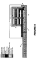
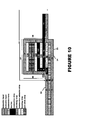
- the layer 50 need not include a haven portion 52 (see Figure 8 ). If the layer 40 is cured together with the rest, then the layer 50 may need to include a haven portion 52 to prevent conductive ink leaking (see Figure 9 ). If the bus-bar harbored section 72 is oriented outward, rather than inward, the dielectric layer 50 can form haven walls 54-56 and the dielectric layer 40 can include a tail section 47 underlying the bus-bar section 71 (see Figure 10 ).
- the "redundant" strip 110 and corresponding strips 120-150 are omitted.
- the harbored section 72 of the bus bar 70 can be secured directly to the haven roof 45 by the adhesive strip 100. This modification can be used when redundancy and/or reinforcement are not necessary.
- a coupling-agent 170 may be coated on the face of the bus bar 70 adjacent to the adhesive strip 90 and/or a coupling-agent 180 may be coated on the face of the bus bar 70 adjacent to the adhesive strip 100.
- the coupling agents 170/180 can comprise agents that promote and strengthen adhesion of the conductive adhesive 90/100 to the bus bar 70.
- a suitable coupling agent would be one that can react with the conductive resin in the adhesive and form a covalent bond.
- the adhesive strip 90/100 is a silver-filled epoxy adhesive (e.g. , Creative Materials 128-4A/B)
- the coupling agent 170/180 can contain NuSil Sp170 available from NuSil Silicone Technology.
- a protection inset 190 is included to further protect the bus bar 70 during perforation procedures.
- the inset 190 can be made of a high temperature elastomer such as silicone and/or fluorocarbon elastomers.
- the inset 190 can be used in addition to the shielding strip 80 (as shown) or as an alternative thereto.
- the inset 190 can be situated within the pocket formed by the conductive lane 60. More particularly, the inset 190 can be located in the bend of the dielectric layer 50 ( e.g ., between its ceiling section 54 and the underlying segment of its façade section 51). With this placement, the setting of the inset 190 is assured, even if it does not fully bond to the pocket.
- the heat distribution pattern for the heater 30 is shown in Figure 14 and Figure 15 .
- excessively cold spots do not exist on the exterior surface 31 (i.e ., the primary heating surface) in the regions overlying the havens 34.
- cold spots do strategically occupy the havens 34 on the interior surface 32 where heat is not needed and may even be detrimental.
- a plurality of heaters 30 can be laterally disposed edge-to-edge to service a larger aircraft area such as a nacelle lip or a wing. With such an arrangement, any overheating issues along the edges are compounded by the close-proximity of the neighboring heaters 30. As is shown in Figures 16 and 17 , the haven construction does not result in overheated lateral edges in the heaters 30.
- the thickness of the layers, lanes, bars, and strips are greatly exaggerated. If such thicknesses were drawn to scale, it would be difficult to decipher and/or number the various stratums. And although corners and turns are represented as right angles, they are more likely to follow smooth curved paths resembling folds as oppose to perpendicular street intersections. Furthermore, although the drawings reflect approximately equal-thickness among the stratums, this would probably not be the case.
- the conductive lanes 60 could be somewhat thicker ( e.g. , two to five times as thick) as the dielectric layers 40-50, the bus bar 70, and/or the adhesive strips 90-100.
- havens 34 shelter vulnerable interfaces, mitigate cold spots on the primary heating surface 31, shield sensitive junctions during soldering steps, and accommodate perforation procedures, guard against adhesive migration during manufacture, offer electrical-connection redundancy, reinforce delamination-prone region, secure conductive seams, and/or address thermal stress concerns.
- the aircraft 10, the heating system 26, the heater 30, the platform 33, the haven 34, and/or the layers therein have been shown and described with respect to a certain embodiment or embodiments, it is obvious that equivalent alterations and modifications will occur to others skilled in the art upon the reading and understanding of this specification and the annexed drawings.
- the heater 30 need not be used in an aircraft application, as it may be apt for use in other fields.
- the conductive lanes 60 need not comprise fabric, as the haven 34 may provides features helpful with other types of heating elements.
- each feature may be combined with one or more other features as may be desired and/or advantageous in a given situation.
Abstract
Description
- An aircraft heating system can comprise an electrothermal heater that converts electrical energy into thermal energy (i.e., heat). Graphite fabric has recently shown great promise for functioning as the heating element in aircraft applications. Graphite heaters are lightweight, robust, provide a well-distributed heat pattern, and have a stable temperature coefficient. Moreover, such material is usually easily conformable to the three-dimensional shapes so commonly found on aircraft.
- An aircraft heating system is provided wherein the heater comprises bus-bar havens that are compatible with graphite-fabric heating lanes. The havens shelter vulnerable interfaces, mitigate cold spots on the primary heating surface, shield sensitive junctions, guard against adhesive migration during manufacture, offer electrical-connection redundancy, reinforce delamination-prone regions, fortify conductive seams, and/or address thermal stress concerns.
-
-
Figure 1 is a view of an aircraft incorporating the heating system. -
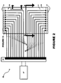
Figure 2 is a schematic view of the heating system. -
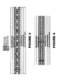
Figures 3 and 4 are sectional views as seen along the corresponding lines inFigure 2 . -
Figure 5 is a close-up view of the corresponding circled area inFigure 2 . -
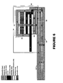
Figure 6 is a sectional view as seen along the corresponding line inFigure 5 . -
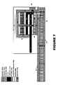
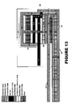
Figures 7-13 are views similar toFigure 6 , showing some modified haven constructions. -
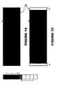
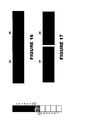
Figures 14-17 depict heat distribution patterns. - Referring now to the drawings, and initially to
Figure 1 , anaircraft 10 is shown. Theaircraft 10 comprisesfuselage 12,wings 14, andengines 16. Eachengine 16 comprisesinternal engine components 18 and anacelle 20 which houses theinternal engine components 18. Eachnacelle 20 includes aninlet lip 22 which defines the inlet opening 24 through which air enters theengine 16. - The
nacelle 20, theinlet lip 22, and other areas of theaircraft 10 can be protected from ice accumulation during flight by theelectrical heating system 26 shown inFigure 2 . Thesystem 26 includes anelectrical power source 27 which, in an aircraft application, could be an onboard generator. Thesource 27 provides power to acontroller 28 which is connected, viaelectric conductors 29 to anelectrothermal heater 30. - The
heater 30 is drawn flat inFigure 2 for ease in illustration. But it can instead have a roughly parabolic profile to match the geometry of the aircraft area being heated. If, for example, theheater 30 is intended to heat the engine'sinlet lip 22, this contour allows it to bend therearound to cover both inner and outer regions. And if theheater 30 is intended to heat awing 14, this geometry lends to curving around its leading edge to cover both upper and lower regions. Analogous arrangements could be used with the stabilizers, or any other aircraft area requiring heating. For larger aircraft areas (e.g., thenacelle lip 22 or the wings 14), a plurality of theheaters 30 can be arranged lateral-edge to lateral-edge to collectively service the entire ice-susceptible vicinity. - The
heater 30 has an exterior surface 31 (covered inFigure 2 ), aninterior surface 32,lateral edges 33, andhavens 34 along its lateral edges. Theexterior surface 31 of theheater 30 typically faces outward and it can function as the primary heating surface. Theinterior surface 32 of theheater 30 faces inward and can be, for example, mounted to the relevant aircraft structure. - Referring now to
Figures 3-4 , theheater 30 comprises adielectric layer 40 and adielectric layer 50. The layers 40-50 can made be of one or more plies of electrically insulating glass cloth that are impregnated with a suitable curable resin. Theheater 30 can include other layers adjacent itsdielectric layer 40 and/or its dielectric layer 50 (e.g., a bonding, erosion-shield, and/or structural layers). - The
heater 30 additionally comprisesconductive lanes 60 sandwiched between the dielectric layers 40-50. Theheater 30 can have oneconductive lane 60, twoconductive lanes 60, or more (e.g., at least three lanes, at least four lanes, at least six lanes, at least eight lanes, at least ten lanes, etc.). - The
conductive lanes 60 are the heat-generating elements that convert electrical power into thermal power (i.e., heat). They each establish an electrical path between its lateral ends and affords ohmic generation of heat by dint of its electrical resistance. Thelanes 60 can each comprise a resin-impregnated woven fabric that includes electrically-conductive fibers (e.g., carbon and/or graphite fibers). Thelanes 60 can be distinct fabric strips spaced apart from each other and/or isolated from each other via inter-strip insulation. - The
dielectric layer 40 includes a façade section 41, thedielectric layer 50 includes afaçade section 51, and eachconductive lane 60 includes a façade section 61. The façade sections 41/51/61 span the length of theheater 30 and form theprimary heating surface 31. The layers 40-50 and/or thelanes 60 can each also include a haven portion 42/52/62 on the lateral ends of its façade section 41/51/61. The portions 42/52/62 contribute to the construction of thehavens 34, as is explained in more detail below. - Although not specifically shown in the drawings, the
layer 40, thelayer 50, and/or thelanes 60 can include a plurality of aligned openings established to tailor electrical resistance and/or enhance noise attenuation. - Turning now to
Figure 5 , theheater 30 also comprisesbus bars 70 aligned along eachlateral edge 33. As is best seen by referring briefly back toFigure 2 , a pair ofbus bars 70 is provided perconductive lane 60, with one at each end of the electric path formed thereby. Eachbus bar 70 has asection 71 adapted for electrical connection to the power source 27 (either directly or through a controller 28). - The bus-bar material should be electrically conductive and compatible with the electrical connection of the
lines 28. For example, if thelines 28 are to be soldered to thebus bar 70, copper would be an appropriate material selection. If so (and in any event), thebus bar 70 can be a very thin plate (e.g., in the range or about 0.05 mm to about 0.13 mm thick). Such thinness can help reduce thermal stress in the fabric-bus interface caused by temperature-expansion mismatches between graphite and copper. - As is best seen by referring to
Figure 6 , theheater 30 further comprises a set of strips 80-150 for eachbus bar 60. Theheater 30 can be made by compiling the layers 40-50, thelanes 60, thebus bars 70, and the strips 80-150, and then curing this compilation to form a composite structure. - The
haven 34 can be viewed as comprising afloor 35, adistal wall 36, aroof 37, an upper proximal wall 38 (above the bus-bar section 71) and a lower proximal wall 39 (below the bus-bar section 71). - The haven portion 42 of the
dielectric layer 40 includes distal side sections 43-44 that form the haven'sdistal wall 36. This portion 42 also includes aceiling section 45 that forms the haven'sroof 37 and a proximal-side section 46 that forms the haven's upperproximal wall 38. - The haven portion 52 of the
dielectric layer 50 includes a distal bend section 53, a ceiling section 54, and atail section 55 extending therefrom. Thetail section 55 projects outward and is positioned below the bus-bar section 71. This projection functions as an underpinning for bus-bar section 71 when thelines 29 are soldered or otherwise electrically connected thereto. - The haven portion 62 of the
conductive lane 60 includes a distal bend section 63 and aceiling section 64. The bend section 63 is located between the distal edge section 43 of thedielectric layer 40 and the bend section 53 of thedielectric layer 50. Theceiling section 64 is spaced above the façade section 61 to thereby form a pocket. The bend section 53 and the ceiling section 54 (but not the tail section 55) of thedielectric layer 50 are situated within this pocket. - As was indicated above, the
bus bar 70 has asection 71 adapted for electrical connection to thepower source 27 and this section planks beyond the haven'sproximal walls bus bar 71 also has asection 72 harbored within thehaven 34 and electrically connected toceiling 64 of theconductive lane 60. - Accordingly, the lane's
ceiling section 64 can serve only as an attachment platform for thebus bar 70. Andbus bar 70 is not attached to thesegment 65 of the lane's facade section 61 underlying thehaven 34, whereby it can serve only as part of theprimary heating surface 31. In this manner, cold spots on thesegment 65 are mitigated as bus-bar attachment/insulation does not interfere with its heating function. Likewise, overheating is alleviated by thebus bar 70 not being surrounded by heating elements. This improves heat distribution patterns in theheater 30. - Additionally or alternatively, the bus-
bar section 71 is distanced from the shelter provided by the dielectric layer 40 (e.g., itssections 44, 45, 46). Additionally or alternatively, it is disassociated from the (adhesive) strips 90 and 100. This remoteness can be beneficial when soldering or other techniques are performed to electrically connect the bus-bar section 71 to thepower source 27. Specifically, for example, this seclusion can help minimize the thermal degradation of the underlying conductive adhesive and/or mechanical stress on the interface caused by such electrical-connection procedures. - The strip 80 comprises a dielectric polymer and the
strip 90 comprises a conductive adhesive. The polymer strip 80 is located within the pocket formed byconductive lane 60. More specifically, the strip 80 is situated between the ceiling section 54 of thedielectric layer 50 and theceiling section 64 of theconductive lane 60. Theadhesive strip 90 is located on the lane'sceiling 64 whereby this conductive section 63 is sandwiched between thestrips 80 and 90. - The strip 80 prevents migration of conductive adhesive from the
strip 90 towards the façade section 61 of theconductive lane 60 during the manufacturing process. To this end, the strip 80 can be made of a polymer having good dielectric qualities and non-permeable with respect to the strip 80. Kapton™ is a strong contender for this cause, because of its good dielectric qualities, and its availability in thin sheets. - The
strip 90 can be made of a conductive adhesive able to withstand high temperatures and can tolerate a wide temperature range during the course of a flight. Specifically, for example, the adhesive can be effective in temperatures ranging from -90EC to 200EC. A suitable adhesive is a silver-filled high temperature-cryogenic epoxy adhesive available from Creative Materials (CMI 128-4A/B) or from Master Bond (Supreme 10 HT/S). - The
strip 100 can be another adhesive strip located on the other face of the harboredsection 72 of thebus bar 70. It can be made of the same or a similar material as adhesive strip 90 (i.e., electrically conductive, high temperature tolerance, and wide temperature range compatibility). - The
strip 110 can comprise aceiling section 111, a bend section 112, and ajunction section 113. Theceiling section 111 is bonded (via adhesive strip 100) to theharbor section 72 of thebus bar 70 and thus electrically connected thereto. The bend section 112 is sandwiched between the distal section 43 of thedielectric layer 40 and the distal ends ofbus bar 70 and the adhesive strips 90-100. Thejunction section 113 is secured to theceiling section 64 of theconductive lane 60. - The
strip 110 can be made of the same conductive fabric as thelanes 60 and is, in any event, electrically conductive. Thestrip 110 offers redundancy in the electrical connection between thebus bar 70 and thelane 60. If the lane'sceiling section 64 were somehow electrically isolated from thebus bar 70, a current path would still be provided by thestrip 110. - Additionally or alternatively, the
strip 110 serves as a shield for a delamination-prone district of thehaven 34. Specifically, for example, its bend section 112 seals the distal ends of the adhesive-copper-adhesive interface of thebus bar 70 and the adhesive strips 90-100. This reinforcement is directed at the part of thehaven 34 most vulnerable to stratum separation. - The strips 120-150 provide the
haven 34 with a sliding decoupling between thebus bar 70 and the haven'swalls strips strips adhesive strip 120 bonds theanti-stick strip 130 to thestrip 110 and theadhesive strip 150 bonds theanti-stick strip 140 to the haven's roof (i.e., the ceiling section 44 of the dielectric layer 40). Theadhesive strips - The adjacent faces of the
anti-stick strips strips - In a modified haven construction shown in
Figure 7 , the sections 62 and 63 of theconductive lane 60 are provided by aseparate strip 160. This two-piece construction may be preferred if thelane 60 and thedielectric layer 40 are perforated, to reduce the risk that an opening will fall on the bend 62 and create a line of weakness. The tail 163 of thestrip 160 can be slightly larger than the sum of the perforations diameter and the inter-perforation gap. In this manner, an opening would not electrically disconnect the bend 62 and it would not be too large to cause a cold spot. - In the modified haven constructions shown in
Figures 8-10 , the haven portion 62 of theconductive lane 60 does not include a distal bend section 63 and/or does not include aceiling section 64. This construction can be employed, for example, when it is not crucial to shield thebus bar 70 from heating elements. If thedielectric layer 40 is cured in a secondary operation (i.e., after thedielectric layer 50, theconductive lanes 60, and the strips 70-110 are cured together), thelayer 50 need not include a haven portion 52 (seeFigure 8 ). If thelayer 40 is cured together with the rest, then thelayer 50 may need to include a haven portion 52 to prevent conductive ink leaking (seeFigure 9 ). If the bus-bar harboredsection 72 is oriented outward, rather than inward, thedielectric layer 50 can form haven walls 54-56 and thedielectric layer 40 can include a tail section 47 underlying the bus-bar section 71 (seeFigure 10 ). - In a modified haven construction shown in
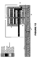
Figure 11 , the "redundant"strip 110 and corresponding strips 120-150 are omitted. The harboredsection 72 of thebus bar 70 can be secured directly to thehaven roof 45 by theadhesive strip 100. This modification can be used when redundancy and/or reinforcement are not necessary. - In the modified haven construction shown in
Figure 12 , a coupling-agent 170 may be coated on the face of thebus bar 70 adjacent to theadhesive strip 90 and/or a coupling-agent 180 may be coated on the face of thebus bar 70 adjacent to theadhesive strip 100. Thecoupling agents 170/180 can comprise agents that promote and strengthen adhesion of the conductive adhesive 90/100 to thebus bar 70. A suitable coupling agent would be one that can react with the conductive resin in the adhesive and form a covalent bond. If, for example, theadhesive strip 90/100 is a silver-filled epoxy adhesive (e.g., Creative Materials 128-4A/B), thecoupling agent 170/180 can contain NuSil Sp170 available from NuSil Silicone Technology. - In the modified haven construction shown in
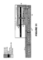
Figure 13 , a protection inset 190 is included to further protect thebus bar 70 during perforation procedures. The inset 190 can be made of a high temperature elastomer such as silicone and/or fluorocarbon elastomers. The inset 190 can be used in addition to the shielding strip 80 (as shown) or as an alternative thereto. The inset 190 can be situated within the pocket formed by theconductive lane 60. More particularly, the inset 190 can be located in the bend of the dielectric layer 50 (e.g., between its ceiling section 54 and the underlying segment of its façade section 51). With this placement, the setting of the inset 190 is assured, even if it does not fully bond to the pocket. - The heat distribution pattern for the
heater 30 is shown inFigure 14 and Figure 15 . Notably, excessively cold spots do not exist on the exterior surface 31 (i.e., the primary heating surface) in the regions overlying thehavens 34. At the same time, cold spots do strategically occupy thehavens 34 on theinterior surface 32 where heat is not needed and may even be detrimental. - As was noted above, a plurality of
heaters 30 can be laterally disposed edge-to-edge to service a larger aircraft area such as a nacelle lip or a wing. With such an arrangement, any overheating issues along the edges are compounded by the close-proximity of the neighboringheaters 30. As is shown inFigures 16 and 17 , the haven construction does not result in overheated lateral edges in theheaters 30. - In the above cross-sectional drawings, the thickness of the layers, lanes, bars, and strips are greatly exaggerated. If such thicknesses were drawn to scale, it would be difficult to decipher and/or number the various stratums. And although corners and turns are represented as right angles, they are more likely to follow smooth curved paths resembling folds as oppose to perpendicular street intersections. Furthermore, although the drawings reflect approximately equal-thickness among the stratums, this would probably not be the case. For example, the
conductive lanes 60 could be somewhat thicker (e.g., two to five times as thick) as the dielectric layers 40-50, thebus bar 70, and/or the adhesive strips 90-100. - One may now appreciate that the
havens 34 shelter vulnerable interfaces, mitigate cold spots on theprimary heating surface 31, shield sensitive junctions during soldering steps, and accommodate perforation procedures, guard against adhesive migration during manufacture, offer electrical-connection redundancy, reinforce delamination-prone region, secure conductive seams, and/or address thermal stress concerns. - Although the
aircraft 10, theheating system 26, theheater 30, theplatform 33, thehaven 34, and/or the layers therein have been shown and described with respect to a certain embodiment or embodiments, it is obvious that equivalent alterations and modifications will occur to others skilled in the art upon the reading and understanding of this specification and the annexed drawings. By way of example, theheater 30 need not be used in an aircraft application, as it may be apt for use in other fields. Additionally or alternatively, theconductive lanes 60 need not comprise fabric, as thehaven 34 may provides features helpful with other types of heating elements. And while certain features may have been described with respect to only one or some embodiments, each feature may be combined with one or more other features as may be desired and/or advantageous in a given situation.
Claims (15)
- An electrothermal heater (30) comprising dielectric layers (40, 50), one or more conductive lanes (60), a pair of bus bars (70) for each conductive lane (60), and a set of strips (80-150) for each bus bar (70); wherein:each dielectric layer (40, 50) has a façade section (41, 51) and each conductive lane (60) has a façade section (61) sandwiched between the dielectric façade sections (41, 51),the façade sections (41, 51, 61) form the primary heating surface (31);each conductive lane (60) establishes an electrical path between its lateral ends;each bus bar (70) has a section (71) adapted for electrical connection to a power source and a harbor section (72) electrically connected to the respective end of the electrical path; andeach set of strips (80-150) forms a haven (34) that shelters the harbor section (72) of its respective bus bar (70).
- An electrothermal heater (30) as set forth in the preceding claim, comprising a plurality of conductive lanes (60).
- An electrothermal heater (30) as set forth in any of the preceding claims, wherein the conductive lane(s) (60) comprise an electrically conductive fabric.
- An electrothermal heater (30) as set forth in the preceding claim,
wherein the fabric comprises a woven fabric that includes electrically-conductive fibers. - An electrothermal heater (30) as set forth in either of the two preceding claims, wherein the fabric affords ohmic generation of heat by dint of its electrical resistance.
- An electrothermal heater (30) as set forth in any of the preceding claims, wherein the dielectric layer (40/50) has a haven portion (42/52) that encloses the distal ends, the proximal ends, and the ceilings of certain strips (100-150), and wherein the dielectric layer (50/40) has a haven portion (52/42) contributing to the formation of the haven (34).
- An electrothermal heater (30) as set forth in the preceding claims, wherein the section (71) of the bus bar (70) extends beyond the haven's proximal walls (38, 39) and wherein the harbor section (72) of the bus bar (70) resides within proximal walls (44 - 46) of the haven (34).
- An electrothermal heater (30) as set forth in any of the preceding claims, wherein the haven (34) has a sliding decoupling between the bus bar (70) and haven walls (44/54, 45/55, 46/56).
- An electrothermal heater (30) as set forth in any of the preceding claims, wherein the haven-forming set of strips comprise a polymer strip (80) situated to prevent migration of adhesive towards a façade section (61) of the conductive lane (60) during the manufacturing process.
- An electrothermal heater (30) as set forth in any of the preceding claims, wherein the haven-forming set of strips comprise an adhesive strip (90) securing the conductive lane (60) to the bus bar (70), wherein this adhesive strip (90) comprises an electrically conductive adhesive that can withstand high temperatures and can tolerate a wide temperature range.
- An electrothermal heater (30) as set forth in any of the preceding claims, wherein the haven-forming set of strips comprise a conductive strip (110) which forms a redundant electrical connection between the bus bar (70) and the conductive lane (60) and/or which reinforces a delamination-prone district of the haven (34).
- An electrothermal heater (30) as set forth in any of the preceding claims, wherein the haven-forming set of strips comprise an anti-stick strip (130) secured to the bus bar (70) and an anti-stick strip (140) secured to a roof (45/55) of the haven (34), wherein the anti-stick strips (130, 140) face each other but are not secured together to form a sliding decoupling.
- An electrothermal heater (30) as set forth in any of the preceding claims, wherein the haven-forming set of strips comprise an inset strip (190) situated in a pocket formed by the conductive lane (60) to protect the bus bar 70 during perforation procedures.
- An electrothermal heater (30) as set forth in any of the preceding claims, wherein at least one of the layers (40, 50), the lanes (60), the bus bars (70), and the sets of strips (80-160) are compiled and cured together to form a composite structure.
- An aircraft (10) comprising an ice-susceptible area and the electrical heating system (26) set forth in any of the preceding claims mounted to provide ice protection for this area.
Applications Claiming Priority (1)
| Application Number | Priority Date | Filing Date | Title |
|---|---|---|---|
| US34916710P | 2010-05-27 | 2010-05-27 |
Publications (3)
| Publication Number | Publication Date |
|---|---|
| EP2390182A2 true EP2390182A2 (en) | 2011-11-30 |
| EP2390182A3 EP2390182A3 (en) | 2014-09-17 |
| EP2390182B1 EP2390182B1 (en) | 2017-04-12 |
Family
ID=44501581
Family Applications (1)
| Application Number | Title | Priority Date | Filing Date |
|---|---|---|---|
| EP11250553.2A Active EP2390182B1 (en) | 2010-05-27 | 2011-05-26 | Aircraft heating system |
Country Status (3)
| Country | Link |
|---|---|
| US (1) | US10293947B2 (en) |
| EP (1) | EP2390182B1 (en) |
| CA (1) | CA2741154C (en) |
Cited By (1)
| Publication number | Priority date | Publication date | Assignee | Title |
|---|---|---|---|---|
| EP3297393A1 (en) * | 2016-09-20 | 2018-03-21 | Goodrich Corporation | Bus bar attachment for carbon nanotube heaters |
Families Citing this family (8)
| Publication number | Priority date | Publication date | Assignee | Title |
|---|---|---|---|---|
| US8159825B1 (en) | 2006-08-25 | 2012-04-17 | Hypres Inc. | Method for fabrication of electrical contacts to superconducting circuits |
| US10368401B2 (en) | 2014-06-03 | 2019-07-30 | Aurora Flight Sciences Corporation | Multi-functional composite structures |
| US10167550B2 (en) | 2014-06-03 | 2019-01-01 | Aurora Flight Sciences Corporation | Multi-functional composite structures |
| US10285219B2 (en) | 2014-09-25 | 2019-05-07 | Aurora Flight Sciences Corporation | Electrical curing of composite structures |
| US11319934B2 (en) * | 2016-06-30 | 2022-05-03 | Vestas Wind Systems A/S | Busbars in a stacking arrangement |
| US10787267B2 (en) * | 2017-05-30 | 2020-09-29 | Bell Helicopter Textron Inc. | Electrical bus arrangement for ice protection systems |
| US11130559B2 (en) * | 2018-08-20 | 2021-09-28 | Goodrich Corporation | Heated panels with ballistic structures |
| GB2584693A (en) * | 2019-06-12 | 2020-12-16 | Rolls Royce Plc | Improving deceleration of a gas turbine |
Family Cites Families (30)
| Publication number | Priority date | Publication date | Assignee | Title |
|---|---|---|---|---|
| US2741692A (en) * | 1952-11-26 | 1956-04-10 | Goodrich Co B F | Electrically heated protective covering for an airfoil and method of making the covering |
| US3397302A (en) * | 1965-12-06 | 1968-08-13 | Harry W. Hosford | Flexible sheet-like electric heater |
| US3557344A (en) | 1969-03-07 | 1971-01-19 | Delta Control Inc | Immersible electrical heating device |
| US3737621A (en) | 1971-11-09 | 1973-06-05 | S Elkins | Water-immersible electrical heating device |
| US3935422A (en) | 1974-02-12 | 1976-01-27 | Burlington Industries, Inc. | Electrically heated laminate with a glass heating fabric |
| US4972197A (en) | 1987-09-03 | 1990-11-20 | Ford Aerospace Corporation | Integral heater for composite structure |
| US4942078A (en) | 1988-09-30 | 1990-07-17 | Rockwell International Corporation | Electrically heated structural composite and method of its manufacture |
| ATE104493T1 (en) | 1990-01-24 | 1994-04-15 | Hastings Otis | ELECTRICALLY CONDUCTIVE LAMINATE FOR TEMPERATURE REGULATION OF SURFACES. |
| CA2176359C (en) * | 1993-11-30 | 2004-01-27 | David Charles Lawson | An electrically conductive composite heater and method of manufacture |
| FR2744872B1 (en) * | 1996-02-08 | 1998-04-10 | Eurocopter France | DEVICE FOR HEATING AN AERODYNAMIC PROFILE |
| US5824996A (en) | 1997-05-13 | 1998-10-20 | Thermosoft International Corp | Electroconductive textile heating element and method of manufacture |
| WO1998009478A1 (en) | 1996-08-29 | 1998-03-05 | Arthur Gurevich | Heating element and method of manufacture |
| FR2756253B1 (en) | 1996-11-27 | 1999-01-29 | Eurocopter France | RESISTIVE ELEMENTS FOR HEATING AN AERODYNAMIC PROFILE, AND DEVICE FOR HEATING AN AERODYNAMIC PROFILE INCORPORATING SUCH ELEMENTS |
| DK0983437T3 (en) | 1997-05-20 | 2004-02-16 | Thermion Systems Int | Apparatus and method for heating and defrosting wind turbine blades |
| US6279856B1 (en) * | 1997-09-22 | 2001-08-28 | Northcoast Technologies | Aircraft de-icing system |
| US5934617A (en) | 1997-09-22 | 1999-08-10 | Northcoast Technologies | De-ice and anti-ice system and method for aircraft surfaces |
| US7202444B2 (en) | 1999-01-25 | 2007-04-10 | Illinois Tool Works Inc. | Flexible seat heater |
| US6373034B1 (en) | 1999-04-22 | 2002-04-16 | Malden Mills Industries, Inc. | Electric heating/warming fabric articles |
| KR100731967B1 (en) | 1999-07-22 | 2007-06-25 | 토요 탄소 가부시키가이샤 | Heating element |
| AU2071701A (en) * | 1999-12-10 | 2001-06-18 | Thermion Systems International | A thermoplastic laminate fabric heater and methods for making same |
| US6870134B2 (en) * | 2002-02-01 | 2005-03-22 | Centre Luxembourgeois De Recherches Pour Le Verre Et La Ceramique S.A. (C.R.V.C.) | Heatable vehicle windshield with bus bars including braided and printed portions |
| FR2866000B1 (en) | 2004-02-11 | 2007-04-06 | Eurocopter France | HEATING MATERIAL COMPOSED OF ELECTRICALLY CONDUCTIVE FIBERS. |
| US20060278631A1 (en) | 2005-06-10 | 2006-12-14 | Challenge Carbon Technology Co., Ltd. Of Taiwan | Laminate fabric heater and method of making |
| ES2341794T3 (en) | 2005-08-25 | 2010-06-28 | Gkn Aerospace Services Limited | AUXILIARY WING OF THE WING ATTACK OF THE WING OF AN AIRPLANE. |
| AU2006299636A1 (en) | 2005-09-29 | 2007-04-12 | Augustine Biomedical And Design Llc | Heating blanket and pads |
| US7340933B2 (en) | 2006-02-16 | 2008-03-11 | Rohr, Inc. | Stretch forming method for a sheet metal skin segment having compound curvatures |
| US7291815B2 (en) | 2006-02-24 | 2007-11-06 | Goodrich Corporation | Composite ice protection heater and method of producing same |
| US7923668B2 (en) * | 2006-02-24 | 2011-04-12 | Rohr, Inc. | Acoustic nacelle inlet lip having composite construction and an integral electric ice protection heater disposed therein |
| EP1880832A1 (en) * | 2006-07-18 | 2008-01-23 | Nederlandse Organisatie voor Toegepast-Natuuurwetenschappelijk Onderzoek TNO | Method and system for layerwise production of a tangible object |
| US7716815B2 (en) | 2007-10-12 | 2010-05-18 | Bariaq Co., Ltd | Process for fabricating a cloth-like heating element with two pairs of electrical conductors and parallel circuits |
-
2011
- 2011-05-24 US US13/115,081 patent/US10293947B2/en active Active
- 2011-05-26 EP EP11250553.2A patent/EP2390182B1/en active Active
- 2011-05-26 CA CA2741154A patent/CA2741154C/en active Active
Non-Patent Citations (1)
| Title |
|---|
| None |
Cited By (2)
| Publication number | Priority date | Publication date | Assignee | Title |
|---|---|---|---|---|
| EP3297393A1 (en) * | 2016-09-20 | 2018-03-21 | Goodrich Corporation | Bus bar attachment for carbon nanotube heaters |
| US10470249B2 (en) | 2016-09-20 | 2019-11-05 | Goodrich Corporation | Bus bar attachment for carbon nanotube heaters |
Also Published As
| Publication number | Publication date |
|---|---|
| US10293947B2 (en) | 2019-05-21 |
| EP2390182B1 (en) | 2017-04-12 |
| US20110290786A1 (en) | 2011-12-01 |
| CA2741154C (en) | 2018-07-17 |
| CA2741154A1 (en) | 2011-11-27 |
| EP2390182A3 (en) | 2014-09-17 |
Similar Documents
| Publication | Publication Date | Title |
|---|---|---|
| EP2390182B1 (en) | Aircraft heating system | |
| US10252806B2 (en) | Electrothermal heater mat | |
| US11597524B2 (en) | Heating device and method for manufacturing same | |
| US9868545B2 (en) | Primary structure for an attachment pylon with firewall and thermal layers | |
| EP1820943B1 (en) | Electrothermal heater assembly for anti-icing and deicing a component, corresponding gas turbine engine component and method of forming a heater assembly | |
| EP3333081B1 (en) | Ice protection system for a multi-segment aircraft component | |
| US8006934B2 (en) | Heating architecture for a composite fairing | |
| ES2513515T3 (en) | Electrothermal heating blanket | |
| US10272770B2 (en) | Carbon-fiber-reinforced plastic structure and fuel tank | |
| US8981266B2 (en) | Electrical apparatus | |
| US8714489B2 (en) | Structural bonding arrangement | |
| JP2020008273A (en) | Floor panel assembly, heater, method of making heating layer for floor panel assembly, and method of making floor panel assembly | |
| ES2805365T3 (en) | Composite structure | |
| GB2517465A (en) | Panel for an aircraft | |
| US20190039746A1 (en) | Acoustic honeycomb panel with integrated electrical heater | |
| US11130559B2 (en) | Heated panels with ballistic structures | |
| US10472473B2 (en) | Enhancing z-conductivity in carbon fiber reinforced plastic composite layups | |
| WO2009050460A1 (en) | Bonding of thermoplastics | |
| JP2000356358A (en) | Plate structural member of floor surface plate particularly for aircraft | |
| US20200361612A1 (en) | Resistive heated aircraft component and method for manufacturing said aircraft component | |
| US20160280355A1 (en) | Apparatus and method for heat-sheilding fan duct inner wall | |
| CN110356540A (en) | For aircraft can heating floor panel and floor heating system | |
| CN209938966U (en) | Anti-icing electric heating unit | |
| US20220146119A1 (en) | Heating mat for use in a floor structure, floor structure, and method for producing same | |
| CN110794992A (en) | Touch screen and display device |
Legal Events
| Date | Code | Title | Description |
|---|---|---|---|
| 17P | Request for examination filed |
Effective date: 20110609 |
|
| AK | Designated contracting states |
Kind code of ref document: A2 Designated state(s): AL AT BE BG CH CY CZ DE DK EE ES FI FR GB GR HR HU IE IS IT LI LT LU LV MC MK MT NL NO PL PT RO RS SE SI SK SM TR |
|
| AX | Request for extension of the european patent |
Extension state: BA ME |
|
| PUAI | Public reference made under article 153(3) epc to a published international application that has entered the european phase |
Free format text: ORIGINAL CODE: 0009012 |
|
| PUAL | Search report despatched |
Free format text: ORIGINAL CODE: 0009013 |
|
| AK | Designated contracting states |
Kind code of ref document: A3 Designated state(s): AL AT BE BG CH CY CZ DE DK EE ES FI FR GB GR HR HU IE IS IT LI LT LU LV MC MK MT NL NO PL PT RO RS SE SI SK SM TR |
|
| AX | Request for extension of the european patent |
Extension state: BA ME |
|
| RIC1 | Information provided on ipc code assigned before grant |
Ipc: H05B 3/06 20060101ALI20140813BHEP Ipc: B64D 33/02 20060101ALI20140813BHEP Ipc: B64D 15/12 20060101AFI20140813BHEP |
|
| 17Q | First examination report despatched |
Effective date: 20160216 |
|
| GRAP | Despatch of communication of intention to grant a patent |
Free format text: ORIGINAL CODE: EPIDOSNIGR1 |
|
| INTG | Intention to grant announced |
Effective date: 20161024 |
|
| GRAS | Grant fee paid |
Free format text: ORIGINAL CODE: EPIDOSNIGR3 |
|
| GRAA | (expected) grant |
Free format text: ORIGINAL CODE: 0009210 |
|
| AK | Designated contracting states |
Kind code of ref document: B1 Designated state(s): AL AT BE BG CH CY CZ DE DK EE ES FI FR GB GR HR HU IE IS IT LI LT LU LV MC MK MT NL NO PL PT RO RS SE SI SK SM TR |
|
| REG | Reference to a national code |
Ref country code: GB Ref legal event code: FG4D |
|
| REG | Reference to a national code |
Ref country code: CH Ref legal event code: EP |
|
| REG | Reference to a national code |
Ref country code: FR Ref legal event code: PLFP Year of fee payment: 7 |
|
| REG | Reference to a national code |
Ref country code: IE Ref legal event code: FG4D |
|
| REG | Reference to a national code |
Ref country code: AT Ref legal event code: REF Ref document number: 883579 Country of ref document: AT Kind code of ref document: T Effective date: 20170515 |
|
| REG | Reference to a national code |
Ref country code: DE Ref legal event code: R096 Ref document number: 602011036853 Country of ref document: DE |
|
| REG | Reference to a national code |
Ref country code: NL Ref legal event code: MP Effective date: 20170412 |
|
| REG | Reference to a national code |
Ref country code: LT Ref legal event code: MG4D |
|
| REG | Reference to a national code |
Ref country code: AT Ref legal event code: MK05 Ref document number: 883579 Country of ref document: AT Kind code of ref document: T Effective date: 20170412 |
|
| PG25 | Lapsed in a contracting state [announced via postgrant information from national office to epo] |
Ref country code: NL Free format text: LAPSE BECAUSE OF FAILURE TO SUBMIT A TRANSLATION OF THE DESCRIPTION OR TO PAY THE FEE WITHIN THE PRESCRIBED TIME-LIMIT Effective date: 20170412 |
|
| PG25 | Lapsed in a contracting state [announced via postgrant information from national office to epo] |
Ref country code: AT Free format text: LAPSE BECAUSE OF FAILURE TO SUBMIT A TRANSLATION OF THE DESCRIPTION OR TO PAY THE FEE WITHIN THE PRESCRIBED TIME-LIMIT Effective date: 20170412 Ref country code: ES Free format text: LAPSE BECAUSE OF FAILURE TO SUBMIT A TRANSLATION OF THE DESCRIPTION OR TO PAY THE FEE WITHIN THE PRESCRIBED TIME-LIMIT Effective date: 20170412 Ref country code: NO Free format text: LAPSE BECAUSE OF FAILURE TO SUBMIT A TRANSLATION OF THE DESCRIPTION OR TO PAY THE FEE WITHIN THE PRESCRIBED TIME-LIMIT Effective date: 20170712 Ref country code: LT Free format text: LAPSE BECAUSE OF FAILURE TO SUBMIT A TRANSLATION OF THE DESCRIPTION OR TO PAY THE FEE WITHIN THE PRESCRIBED TIME-LIMIT Effective date: 20170412 Ref country code: HR Free format text: LAPSE BECAUSE OF FAILURE TO SUBMIT A TRANSLATION OF THE DESCRIPTION OR TO PAY THE FEE WITHIN THE PRESCRIBED TIME-LIMIT Effective date: 20170412 Ref country code: GR Free format text: LAPSE BECAUSE OF FAILURE TO SUBMIT A TRANSLATION OF THE DESCRIPTION OR TO PAY THE FEE WITHIN THE PRESCRIBED TIME-LIMIT Effective date: 20170713 Ref country code: FI Free format text: LAPSE BECAUSE OF FAILURE TO SUBMIT A TRANSLATION OF THE DESCRIPTION OR TO PAY THE FEE WITHIN THE PRESCRIBED TIME-LIMIT Effective date: 20170412 |
|
| PG25 | Lapsed in a contracting state [announced via postgrant information from national office to epo] |
Ref country code: LV Free format text: LAPSE BECAUSE OF FAILURE TO SUBMIT A TRANSLATION OF THE DESCRIPTION OR TO PAY THE FEE WITHIN THE PRESCRIBED TIME-LIMIT Effective date: 20170412 Ref country code: PL Free format text: LAPSE BECAUSE OF FAILURE TO SUBMIT A TRANSLATION OF THE DESCRIPTION OR TO PAY THE FEE WITHIN THE PRESCRIBED TIME-LIMIT Effective date: 20170412 Ref country code: IS Free format text: LAPSE BECAUSE OF FAILURE TO SUBMIT A TRANSLATION OF THE DESCRIPTION OR TO PAY THE FEE WITHIN THE PRESCRIBED TIME-LIMIT Effective date: 20170812 Ref country code: SE Free format text: LAPSE BECAUSE OF FAILURE TO SUBMIT A TRANSLATION OF THE DESCRIPTION OR TO PAY THE FEE WITHIN THE PRESCRIBED TIME-LIMIT Effective date: 20170412 Ref country code: BG Free format text: LAPSE BECAUSE OF FAILURE TO SUBMIT A TRANSLATION OF THE DESCRIPTION OR TO PAY THE FEE WITHIN THE PRESCRIBED TIME-LIMIT Effective date: 20170712 Ref country code: RS Free format text: LAPSE BECAUSE OF FAILURE TO SUBMIT A TRANSLATION OF THE DESCRIPTION OR TO PAY THE FEE WITHIN THE PRESCRIBED TIME-LIMIT Effective date: 20170412 |
|
| REG | Reference to a national code |
Ref country code: CH Ref legal event code: PL |
|
| REG | Reference to a national code |
Ref country code: DE Ref legal event code: R097 Ref document number: 602011036853 Country of ref document: DE |
|
| PG25 | Lapsed in a contracting state [announced via postgrant information from national office to epo] |
Ref country code: MC Free format text: LAPSE BECAUSE OF FAILURE TO SUBMIT A TRANSLATION OF THE DESCRIPTION OR TO PAY THE FEE WITHIN THE PRESCRIBED TIME-LIMIT Effective date: 20170412 Ref country code: DK Free format text: LAPSE BECAUSE OF FAILURE TO SUBMIT A TRANSLATION OF THE DESCRIPTION OR TO PAY THE FEE WITHIN THE PRESCRIBED TIME-LIMIT Effective date: 20170412 Ref country code: CZ Free format text: LAPSE BECAUSE OF FAILURE TO SUBMIT A TRANSLATION OF THE DESCRIPTION OR TO PAY THE FEE WITHIN THE PRESCRIBED TIME-LIMIT Effective date: 20170412 Ref country code: RO Free format text: LAPSE BECAUSE OF FAILURE TO SUBMIT A TRANSLATION OF THE DESCRIPTION OR TO PAY THE FEE WITHIN THE PRESCRIBED TIME-LIMIT Effective date: 20170412 Ref country code: EE Free format text: LAPSE BECAUSE OF FAILURE TO SUBMIT A TRANSLATION OF THE DESCRIPTION OR TO PAY THE FEE WITHIN THE PRESCRIBED TIME-LIMIT Effective date: 20170412 Ref country code: SK Free format text: LAPSE BECAUSE OF FAILURE TO SUBMIT A TRANSLATION OF THE DESCRIPTION OR TO PAY THE FEE WITHIN THE PRESCRIBED TIME-LIMIT Effective date: 20170412 |
|
| PLBE | No opposition filed within time limit |
Free format text: ORIGINAL CODE: 0009261 |
|
| STAA | Information on the status of an ep patent application or granted ep patent |
Free format text: STATUS: NO OPPOSITION FILED WITHIN TIME LIMIT |
|
| REG | Reference to a national code |
Ref country code: IE Ref legal event code: MM4A |
|
| PG25 | Lapsed in a contracting state [announced via postgrant information from national office to epo] |
Ref country code: IT Free format text: LAPSE BECAUSE OF FAILURE TO SUBMIT A TRANSLATION OF THE DESCRIPTION OR TO PAY THE FEE WITHIN THE PRESCRIBED TIME-LIMIT Effective date: 20170412 Ref country code: LI Free format text: LAPSE BECAUSE OF NON-PAYMENT OF DUE FEES Effective date: 20170531 Ref country code: SM Free format text: LAPSE BECAUSE OF FAILURE TO SUBMIT A TRANSLATION OF THE DESCRIPTION OR TO PAY THE FEE WITHIN THE PRESCRIBED TIME-LIMIT Effective date: 20170412 Ref country code: CH Free format text: LAPSE BECAUSE OF NON-PAYMENT OF DUE FEES Effective date: 20170531 |
|
| 26N | No opposition filed |
Effective date: 20180115 |
|
| PG25 | Lapsed in a contracting state [announced via postgrant information from national office to epo] |
Ref country code: LU Free format text: LAPSE BECAUSE OF NON-PAYMENT OF DUE FEES Effective date: 20170526 |
|
| REG | Reference to a national code |
Ref country code: FR Ref legal event code: PLFP Year of fee payment: 8 |
|
| REG | Reference to a national code |
Ref country code: BE Ref legal event code: MM Effective date: 20170531 |
|
| PG25 | Lapsed in a contracting state [announced via postgrant information from national office to epo] |
Ref country code: IE Free format text: LAPSE BECAUSE OF NON-PAYMENT OF DUE FEES Effective date: 20170526 |
|
| PG25 | Lapsed in a contracting state [announced via postgrant information from national office to epo] |
Ref country code: SI Free format text: LAPSE BECAUSE OF FAILURE TO SUBMIT A TRANSLATION OF THE DESCRIPTION OR TO PAY THE FEE WITHIN THE PRESCRIBED TIME-LIMIT Effective date: 20170412 |
|
| PG25 | Lapsed in a contracting state [announced via postgrant information from national office to epo] |
Ref country code: BE Free format text: LAPSE BECAUSE OF NON-PAYMENT OF DUE FEES Effective date: 20170531 |
|
| PG25 | Lapsed in a contracting state [announced via postgrant information from national office to epo] |
Ref country code: MT Free format text: LAPSE BECAUSE OF NON-PAYMENT OF DUE FEES Effective date: 20170526 |
|
| PG25 | Lapsed in a contracting state [announced via postgrant information from national office to epo] |
Ref country code: HU Free format text: LAPSE BECAUSE OF FAILURE TO SUBMIT A TRANSLATION OF THE DESCRIPTION OR TO PAY THE FEE WITHIN THE PRESCRIBED TIME-LIMIT; INVALID AB INITIO Effective date: 20110526 |
|
| PG25 | Lapsed in a contracting state [announced via postgrant information from national office to epo] |
Ref country code: CY Free format text: LAPSE BECAUSE OF NON-PAYMENT OF DUE FEES Effective date: 20170412 |
|
| PG25 | Lapsed in a contracting state [announced via postgrant information from national office to epo] |
Ref country code: MK Free format text: LAPSE BECAUSE OF FAILURE TO SUBMIT A TRANSLATION OF THE DESCRIPTION OR TO PAY THE FEE WITHIN THE PRESCRIBED TIME-LIMIT Effective date: 20170412 |
|
| PG25 | Lapsed in a contracting state [announced via postgrant information from national office to epo] |
Ref country code: TR Free format text: LAPSE BECAUSE OF FAILURE TO SUBMIT A TRANSLATION OF THE DESCRIPTION OR TO PAY THE FEE WITHIN THE PRESCRIBED TIME-LIMIT Effective date: 20170412 |
|
| PG25 | Lapsed in a contracting state [announced via postgrant information from national office to epo] |
Ref country code: PT Free format text: LAPSE BECAUSE OF FAILURE TO SUBMIT A TRANSLATION OF THE DESCRIPTION OR TO PAY THE FEE WITHIN THE PRESCRIBED TIME-LIMIT Effective date: 20170412 |
|
| PG25 | Lapsed in a contracting state [announced via postgrant information from national office to epo] |
Ref country code: AL Free format text: LAPSE BECAUSE OF FAILURE TO SUBMIT A TRANSLATION OF THE DESCRIPTION OR TO PAY THE FEE WITHIN THE PRESCRIBED TIME-LIMIT Effective date: 20170412 |
|
| REG | Reference to a national code |
Ref country code: DE Ref legal event code: R082 Ref document number: 602011036853 Country of ref document: DE |
|
| P01 | Opt-out of the competence of the unified patent court (upc) registered |
Effective date: 20230522 |
|
| PGFP | Annual fee paid to national office [announced via postgrant information from national office to epo] |
Ref country code: FR Payment date: 20230420 Year of fee payment: 13 Ref country code: DE Payment date: 20230419 Year of fee payment: 13 |
|
| PGFP | Annual fee paid to national office [announced via postgrant information from national office to epo] |
Ref country code: GB Payment date: 20230420 Year of fee payment: 13 |