EP2390133A1 - Active seat suspension system - Google Patents
Active seat suspension system Download PDFInfo
- Publication number
- EP2390133A1 EP2390133A1 EP11166710A EP11166710A EP2390133A1 EP 2390133 A1 EP2390133 A1 EP 2390133A1 EP 11166710 A EP11166710 A EP 11166710A EP 11166710 A EP11166710 A EP 11166710A EP 2390133 A1 EP2390133 A1 EP 2390133A1
- Authority
- EP
- European Patent Office
- Prior art keywords
- link
- suspension system
- outer housing
- output shaft
- base frame
- Prior art date
- Legal status (The legal status is an assumption and is not a legal conclusion. Google has not performed a legal analysis and makes no representation as to the accuracy of the status listed.)
- Granted
Links
- 239000000725 suspension Substances 0.000 title claims abstract description 27
- 230000005540 biological transmission Effects 0.000 claims description 2
- 238000010276 construction Methods 0.000 description 1
- 210000005069 ears Anatomy 0.000 description 1
- 239000012530 fluid Substances 0.000 description 1
- 238000000034 method Methods 0.000 description 1
Images

Classifications
-
- B—PERFORMING OPERATIONS; TRANSPORTING
- B60—VEHICLES IN GENERAL
- B60N—SEATS SPECIALLY ADAPTED FOR VEHICLES; VEHICLE PASSENGER ACCOMMODATION NOT OTHERWISE PROVIDED FOR
- B60N2/00—Seats specially adapted for vehicles; Arrangement or mounting of seats in vehicles
- B60N2/50—Seat suspension devices
- B60N2/501—Seat suspension devices actively controlled suspension, e.g. electronic control
-
- B—PERFORMING OPERATIONS; TRANSPORTING
- B60—VEHICLES IN GENERAL
- B60N—SEATS SPECIALLY ADAPTED FOR VEHICLES; VEHICLE PASSENGER ACCOMMODATION NOT OTHERWISE PROVIDED FOR
- B60N2/00—Seats specially adapted for vehicles; Arrangement or mounting of seats in vehicles
- B60N2/02—Seats specially adapted for vehicles; Arrangement or mounting of seats in vehicles the seat or part thereof being movable, e.g. adjustable
- B60N2/0224—Non-manual adjustments, e.g. with electrical operation
- B60N2/02246—Electric motors therefor
- B60N2/02258—Electric motors therefor characterised by the mounting of the electric motor for adjusting the seat
-
- B—PERFORMING OPERATIONS; TRANSPORTING
- B60—VEHICLES IN GENERAL
- B60N—SEATS SPECIALLY ADAPTED FOR VEHICLES; VEHICLE PASSENGER ACCOMMODATION NOT OTHERWISE PROVIDED FOR
- B60N2/00—Seats specially adapted for vehicles; Arrangement or mounting of seats in vehicles
- B60N2/50—Seat suspension devices
- B60N2/502—Seat suspension devices attached to the base of the seat
-
- B—PERFORMING OPERATIONS; TRANSPORTING
- B60—VEHICLES IN GENERAL
- B60N—SEATS SPECIALLY ADAPTED FOR VEHICLES; VEHICLE PASSENGER ACCOMMODATION NOT OTHERWISE PROVIDED FOR
- B60N2/00—Seats specially adapted for vehicles; Arrangement or mounting of seats in vehicles
- B60N2/50—Seat suspension devices
- B60N2/506—Seat guided by rods
- B60N2/508—Scissors-like structure
Definitions
- Agricultural and construction equipment must often be driven over rough terrain. As a result, the operator may experience a bumpy or uncomfortable ride.
- operator seats have been equipped with a suspension, typically a passive system consisting of an air spring and hydraulic damper.
- active seat suspension systems have been used wherein the hydraulic damper is replaced with a hydraulic cylinder. While significantly improving the ride by actively controlling seat top velocity, the suspension performance is limited by the response speed of the hydraulic system, including a hydraulic control valve for the hydraulic cylinder. Additionally, a hydraulic active seat suspension system can be noisy due to the hydraulic fluid flow.
- Such an active seat suspension system also requires high pressure hydraulic lines to enter and/or exit the operator cab, consumes significant power over the minimum required by the suspension due to a pressure reducing valve, and must be tuned to the ride performance of individual vehicles, which requires hardware changes to the hydraulic control valve.
- an object of this invention is to provide an active seat suspension system which is quiet and is capable for being actively controlled.
- a further object of the invention is to provide such an active seat suspension system which does not require high pressure hydraulic lines to enter and/or exit the operator cab.
- a further object of the invention is to provide such an active seat suspension system which consumes little power.
- an active seat suspension system comprises a base frame, a seat carrier frame, and a linkage mounted on the base frame and supporting the seat carrier frame.
- the linkage comprises a first link which is pivotally coupled to the base frame and the seat carrier frame.
- the linkage further comprises a second link which is pivotally coupled to the base frame and the seat carrier frame and which is pivotally coupled to the first link about a link pivot axis A.
- a rotary motor has an outer housing and an output shaft which rotates with respect to the outer housing. The outer housing is coupled to the first link and the output shaft is drivingly coupled to the second link, so that rotation of the output shaft relative to the outer housing causes the first and second links to rotate relative to each other and varies a space between the seat carrier frame and the base frame.
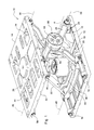
- the active seat suspension system 10 includes a base frame 12 for mounting on a vehicle chassis and a seat carrier frame 14 which is adapted to support a seat assembly (not shown).
- the seat carrier frame 14 is supported with respect to the base frame 12 by a linkage 16, preferably a scissors mechanism.
- the linkage 16 includes a first link 19 with a pair of first arms 20 and 22, and a second link 21 with a pair of second arms 24 and 26.
- First arms 20 and 22 are interconnected by an upper cross arm 28 and a lower cross arm 30.
- Second arms 24 and 26 are interconnected by an upper cross arm 32 and a lower cross arm 34.
- first arms 20 and 22 are pivotally coupled to one end of the seat carrier frame 14 at a pivot axis 36.
- Lower ends of second arms 24 and 26 are pivotally coupled to one end of the base frame 12 at a pivot axis 38.
- Upper ends of second arms 24 and 26 are pivotally coupled to an upper slide member 40 at a pivot axis 42.
- Lower ends of first arms 20 and 22 are pivotally coupled to a lower slide member 44 at a pivot axis 46.
- the upper slide member 40 is slidably supported by upper slide rods 48 and 50 which are fixed to the seat carrier frame 14.
- the lower slide member 44 is slidably supported by lower slide rods 52 and 54 which are fixed to the base frame 12.
- First arm 20 has a central portion 60 which surrounds a central opening 62.
- Second arm 24 has a central portion 64 which surrounds a central opening 66.
- the active seat suspension system 10 also includes a rotary motor 70, preferably an electric motor.
- Rotary motor 70 includes an outer housing 72 and an output shaft 74 which projects outwardly from and rotates with respect to the outer housing 72. Gear teeth are formed on the end of the output shaft 74 forming a sun gear 76.
- Outer housing 72 is received by central opening 62 and is fixed to the first arm 20 by bolts which extend through bores 78 and 80 in the first arm 20 and which are threaded into bores 82 and 84 formed in flanges or ears 86 and 88 which project from the outer housing 72.
- a ring gear 90 is fixedly mounted in or formed on inner side of central opening 66 of central portion 64.
- Three planet gears 92 are mounted within the ring gear 90 for meshing engagement with the sun gear 64 and the ring gear 90.
- the planet gears 92 are rotatably supported by pins 94 which are carried by planet carrier 96.
- Sun gear 76, planet gears 92 and ring gear 90 forming a planetary transmission being part of a gear reduction unit 98 which couples the output shaft 74 to the second arm 24.
- the first and second links 19 and 21 are pivotally coupled to each other about a link pivot axis A, which is aligned with the axis of the output shaft 74.
- the active seat suspension system 10 uses the rotary motor 70 and the gear reduction unit 98 as a primary power delivery source instead of a conventional hydraulic cylinder.
- Rotary motor 70 and gear reduction unit 98 driving one link of the scissors mechanism relative to the other link via a central pivot joint.
- One link is connected to the outer housing 72 and the other link is connected to an output of the gear reduction unit 98.
- the use of a high reduction ratio in the gear reduction unit 98 allows the use of a compact and relatively low torque rotary motor 70.
- the seat suspension system 10 is more responsive dynamically due to the low inertia of the rotary motor 70. It also consumes significantly less power than a comparable active seat suspension system driven by a hydraulic cylinder, since there is no hydraulic pressure reducing valve, and there are no hydraulic lines entering and/or exiting the operator cab.
Landscapes
- Engineering & Computer Science (AREA)
- Aviation & Aerospace Engineering (AREA)
- Transportation (AREA)
- Mechanical Engineering (AREA)
- Seats For Vehicles (AREA)
Abstract
Description
- Agricultural and construction equipment must often be driven over rough terrain. As a result, the operator may experience a bumpy or uncomfortable ride. To minimize the roughness of the operator's ride, operator seats have been equipped with a suspension, typically a passive system consisting of an air spring and hydraulic damper. To improve the ride, active seat suspension systems have been used wherein the hydraulic damper is replaced with a hydraulic cylinder. While significantly improving the ride by actively controlling seat top velocity, the suspension performance is limited by the response speed of the hydraulic system, including a hydraulic control valve for the hydraulic cylinder. Additionally, a hydraulic active seat suspension system can be noisy due to the hydraulic fluid flow. Such an active seat suspension system also requires high pressure hydraulic lines to enter and/or exit the operator cab, consumes significant power over the minimum required by the suspension due to a pressure reducing valve, and must be tuned to the ride performance of individual vehicles, which requires hardware changes to the hydraulic control valve.
- Accordingly, an object of this invention is to provide an active seat suspension system which is quiet and is capable for being actively controlled.
- A further object of the invention is to provide such an active seat suspension system which does not require high pressure hydraulic lines to enter and/or exit the operator cab.
- A further object of the invention is to provide such an active seat suspension system which consumes little power.
- These and other objects are achieved by the present invention, wherein an active seat suspension system comprises a base frame, a seat carrier frame, and a linkage mounted on the base frame and supporting the seat carrier frame. The linkage comprises a first link which is pivotally coupled to the base frame and the seat carrier frame. The linkage further comprises a second link which is pivotally coupled to the base frame and the seat carrier frame and which is pivotally coupled to the first link about a link pivot axis A. A rotary motor has an outer housing and an output shaft which rotates with respect to the outer housing. The outer housing is coupled to the first link and the output shaft is drivingly coupled to the second link, so that rotation of the output shaft relative to the outer housing causes the first and second links to rotate relative to each other and varies a space between the seat carrier frame and the base frame.
- For a complete understanding of the objects, techniques, and structure of the invention reference should be made to the following detailed description and accompanying drawings, wherein similar components are designated by identical reference numerals:
- Fig. 1
- is a perspective view of an active seat suspension system embodying the invention, and
- Fig. 2
- is an exploded perspective view of the active seat suspension system of
Fig. 1 with parts removed for clarity. - Referring to
Fig. 1 , the activeseat suspension system 10 includes abase frame 12 for mounting on a vehicle chassis and aseat carrier frame 14 which is adapted to support a seat assembly (not shown). Theseat carrier frame 14 is supported with respect to thebase frame 12 by alinkage 16, preferably a scissors mechanism. - As best shown in
Fig. 2 , thelinkage 16 includes afirst link 19 with a pair offirst arms second link 21 with a pair ofsecond arms First arms upper cross arm 28 and alower cross arm 30.Second arms upper cross arm 32 and alower cross arm 34. - Upper ends of
first arms seat carrier frame 14 at apivot axis 36. Lower ends ofsecond arms base frame 12 at apivot axis 38. - Upper ends of
second arms upper slide member 40 at apivot axis 42. Lower ends offirst arms lower slide member 44 at apivot axis 46. Theupper slide member 40 is slidably supported byupper slide rods seat carrier frame 14. Thelower slide member 44 is slidably supported bylower slide rods base frame 12. Thus, the lower ends offirst arms base frame 12, and the upper ends of thesecond arms seat carrier frame 12. -
First arm 20 has acentral portion 60 which surrounds acentral opening 62.Second arm 24 has acentral portion 64 which surrounds acentral opening 66. - The active
seat suspension system 10 also includes arotary motor 70, preferably an electric motor.Rotary motor 70 includes anouter housing 72 and anoutput shaft 74 which projects outwardly from and rotates with respect to theouter housing 72. Gear teeth are formed on the end of theoutput shaft 74 forming asun gear 76.Outer housing 72 is received bycentral opening 62 and is fixed to thefirst arm 20 by bolts which extend throughbores first arm 20 and which are threaded intobores ears outer housing 72. - A
ring gear 90 is fixedly mounted in or formed on inner side ofcentral opening 66 ofcentral portion 64. Threeplanet gears 92 are mounted within thering gear 90 for meshing engagement with thesun gear 64 and thering gear 90. Theplanet gears 92 are rotatably supported bypins 94 which are carried byplanet carrier 96. Sungear 76,planet gears 92 andring gear 90 forming a planetary transmission being part of agear reduction unit 98 which couples theoutput shaft 74 to thesecond arm 24. As a result, the first andsecond links output shaft 74. - With this active
seat suspension system 10, rotation of thesun gear 76 by therotary motor 70 causes thefirst arm 20 and thesecond arm 24 to rotate relative to each other, which in turn causes theseat carrier frame 14 to move towards and away from thebase frame 12. - Thus, the active
seat suspension system 10 uses therotary motor 70 and thegear reduction unit 98 as a primary power delivery source instead of a conventional hydraulic cylinder.Rotary motor 70 andgear reduction unit 98 driving one link of the scissors mechanism relative to the other link via a central pivot joint. One link is connected to theouter housing 72 and the other link is connected to an output of thegear reduction unit 98. The use of a high reduction ratio in thegear reduction unit 98 allows the use of a compact and relatively low torquerotary motor 70. Theseat suspension system 10 is more responsive dynamically due to the low inertia of therotary motor 70. It also consumes significantly less power than a comparable active seat suspension system driven by a hydraulic cylinder, since there is no hydraulic pressure reducing valve, and there are no hydraulic lines entering and/or exiting the operator cab.
Claims (7)
- Active seat suspension system, comprising a base frame (12); a seat carrier frame (14); a linkage (16) mounted on the base frame (12) and supporting the seat carrier frame (14), the linkage (16) comprising a first link (19) being pivotally coupled to the base frame (12) and the seat carrier frame (14), and a second link (21) being pivotally coupled to the base frame (12) and the seat carrier frame (14) and being pivotally coupled to the first link (19) about a link pivot axis A; and a rotary motor (70) having an outer housing (72) and an output shaft (74) which rotates with respect to the outer housing (72), the outer housing (72) being coupled to the first link (19), and the output shaft (74) being drivingly coupled to the second link (21), so that rotation of the output shaft (74) relative to the outer housing (72) causes the first and second links (19, 21) to rotate relative to each other and varies a space between the seat carrier frame (14) and the base frame (12).
- The active seat suspension system according to claim 1, characterized by a gear reduction unit (98) coupled between the output shaft (74) and the second link (21).
- The active seat suspension system according to claim 1 or 2, characterized in that the gear reduction unit (98) comprising a planetary transmission having a sun gear (76) fixed to the output shaft (74), a ring gear (90) fixed to the second link (21), and a plurality of planet gears (92) meshing with the sun gear (76) and the ring gear (90).
- The active seat suspension system according to one of claims 1 to 3, characterized in that the output shaft (74) is aligned with the link pivot axis A.
- The active seat suspension system according to one of claims 1 to 4, characterized in that the outer housing (72) is non-rotatably coupled to the first link (19).
- The active seat suspension system according to one of claims 1 to 5, characterized in that the outer housing (72) is received by a central opening (62) formed in the first link (19).
- The active seat suspension system according to one of claims 1 to 6, characterized in that the gear reduction unit (98) is received by a central opening (66) formed in the second link (21).
Applications Claiming Priority (1)
| Application Number | Priority Date | Filing Date | Title |
|---|---|---|---|
| US12/787,047 US8622362B2 (en) | 2010-05-25 | 2010-05-25 | Suspension system |
Publications (2)
| Publication Number | Publication Date |
|---|---|
| EP2390133A1 true EP2390133A1 (en) | 2011-11-30 |
| EP2390133B1 EP2390133B1 (en) | 2019-03-06 |
Family
ID=44544001
Family Applications (1)
| Application Number | Title | Priority Date | Filing Date |
|---|---|---|---|
| EP11166710.1A Active EP2390133B1 (en) | 2010-05-25 | 2011-05-19 | Active seat suspension system |
Country Status (2)
| Country | Link |
|---|---|
| US (1) | US8622362B2 (en) |
| EP (1) | EP2390133B1 (en) |
Cited By (9)
| Publication number | Priority date | Publication date | Assignee | Title |
|---|---|---|---|---|
| WO2014152138A1 (en) * | 2013-03-15 | 2014-09-25 | Bose Corporation | Rotary actuator driven vibration isolation |
| DE102013214453A1 (en) | 2013-07-24 | 2015-01-29 | Ovalo Gmbh | Linear |
| US8973886B2 (en) | 2010-03-26 | 2015-03-10 | Bose Corporation | Actuator including mechanism for converting rotary motion to linear motion |
| DE102013110927A1 (en) * | 2013-10-01 | 2015-04-02 | Grammer Aktiengesellschaft | Vehicle seat or vehicle cabin with a suspension device and utility vehicle |
| CN104842825A (en) * | 2014-02-14 | 2015-08-19 | 格拉默股份有限公司 | Device for damping an upper suspension part in at least one spatial direction with respect to a lower suspension part movable relative thereto |
| US9291300B2 (en) | 2013-03-15 | 2016-03-22 | Bose Corporation | Rotary actuator driven vibration isolation |
| CN105857124A (en) * | 2016-05-27 | 2016-08-17 | 常州嘉盈车辆部件有限公司 | Motor fixing installing frame for electric slide rail |
| CN105966271A (en) * | 2016-05-27 | 2016-09-28 | 常州嘉盈车辆部件有限公司 | Electric sliding rail for car seat |
| US11427115B2 (en) * | 2019-11-06 | 2022-08-30 | Steering Solutions Ip Holding Corporation | System and method for seat vibration cancellation |
Families Citing this family (8)
| Publication number | Priority date | Publication date | Assignee | Title |
|---|---|---|---|---|
| US9052005B2 (en) | 2013-06-12 | 2015-06-09 | Deere & Company | Method of backlash compensation |
| DE102015113176B4 (en) * | 2015-08-10 | 2021-12-30 | Grammer Aktiengesellschaft | Horizontal vibration device for a vehicle seat |
| US9923433B2 (en) * | 2015-08-10 | 2018-03-20 | Bose Corporation | Encoder for a rotary motor |
| GB201514951D0 (en) * | 2015-08-21 | 2015-10-07 | Cobra Seats Technology Ltd | A vehicle seat suspension mechanism |
| DE102015117820B4 (en) * | 2015-10-20 | 2023-02-09 | Grammer Aktiengesellschaft | Device for springing and/or damping an upper part in relation to a lower part and vehicle seat with this device |
| WO2018075257A1 (en) * | 2016-10-17 | 2018-04-26 | Clearmotion Acquisition I Llc | Active vibration isolation system |
| DE102018126404B4 (en) * | 2018-10-23 | 2021-02-25 | Grammer Aktiengesellschaft | Vehicle seat with residual spring travel control |
| US11065989B2 (en) * | 2019-09-18 | 2021-07-20 | Ford Global Technologies, Llc | Scissor lift assembly |
Citations (3)
| Publication number | Priority date | Publication date | Assignee | Title |
|---|---|---|---|---|
| GB2309894A (en) * | 1996-02-08 | 1997-08-13 | Sears Mfg Co | Pneumatic suspension for seats |
| EP1852302A2 (en) * | 2006-05-03 | 2007-11-07 | Bose Corporation | Active suspending |
| US20070278025A1 (en) * | 2006-06-06 | 2007-12-06 | Deere & Company, A Delaware Corporation. | Suspension system having active compensation for vibration |
Family Cites Families (46)
| Publication number | Priority date | Publication date | Assignee | Title |
|---|---|---|---|---|
| DE2736242C3 (en) | 1977-08-11 | 1980-11-27 | Fa. Willibald Grammer, 8450 Amberg | Vehicle seat |
| GB1601370A (en) | 1977-11-29 | 1981-10-28 | Uop Inc | Vehicle seats |
| US4363377A (en) | 1980-09-22 | 1982-12-14 | Deere & Company | Active seat suspension control system |
| DE3228834A1 (en) | 1982-08-02 | 1984-02-02 | Siemens Ag | LIFTING DEVICE FOR IN PARTICULAR A DENTAL PATIENT CHAIR |
| DE3546578C2 (en) | 1985-03-07 | 1988-10-06 | Peter 7989 Eisenharz De Schmidt | Bath tub insert |
| US4913482A (en) | 1985-09-30 | 1990-04-03 | Mitsubishi Denki Kabushiki Kaisha | Seat suspension system for automotive vehicle or the like |
| US4771785A (en) | 1986-07-25 | 1988-09-20 | Resonex, Inc. | Magnetic resonance imaging apparatus and three-axis patient positioning assembly for use therewith |
| US4822094A (en) * | 1988-01-12 | 1989-04-18 | J. I. Case Company | Tractor seat suspension mechanism with automatic seat stop |
| US5060959A (en) | 1988-10-05 | 1991-10-29 | Ford Motor Company | Electrically powered active suspension for a vehicle |
| US5169112A (en) | 1991-08-26 | 1992-12-08 | Milsco Manufacturing Company | Electronic suspension vehicle seat |
| US6126132A (en) | 1995-04-28 | 2000-10-03 | Lear Automotive Dearborn, Inc. | Multi-function single motor seat track actuator assembly |
| JP3147742B2 (en) | 1995-10-24 | 2001-03-19 | 三菱自動車工業株式会社 | Suspension device for vehicle seat |
| US6059253A (en) | 1996-05-14 | 2000-05-09 | Sears Manufacturing Company | Active suspension system for vehicle seats |
| FR2761643B1 (en) | 1997-04-08 | 1999-06-04 | Faure Bertrand Equipements Sa | VARIABLE DAMPING SEAT |
| US5833198A (en) * | 1997-05-22 | 1998-11-10 | Graetz Manufacturing Inc. | Mechanically operated lift table |
| US5941920A (en) | 1997-11-12 | 1999-08-24 | Case Corporation | Control of an active suspension system for a work vehicle based upon a parameter of another vehicle system |
| US6371456B1 (en) | 1999-02-04 | 2002-04-16 | Freightliner Llc | Seat suspension system |
| US6354556B1 (en) | 1999-02-04 | 2002-03-12 | Freightliner Llc | Seat suspension method |
| US6286819B1 (en) | 1999-02-04 | 2001-09-11 | Freightliner Corporation Llc | Vibration damper with latch |
| GB2360447B (en) | 2000-03-20 | 2003-12-31 | Sears Mfg Co | Seat suspension height adjustment |
| US6467748B1 (en) | 2000-09-05 | 2002-10-22 | Deere & Company | Hydraulic circuit for active suspension system |
| US6371459B1 (en) | 2000-09-05 | 2002-04-16 | Deere & Company | Active suspension with offload adjustment |
| US7418324B2 (en) | 2002-03-06 | 2008-08-26 | Vssl Commercial, Inc. | Active suspension for a marine platform |
| US7039512B2 (en) | 2002-03-06 | 2006-05-02 | Vssl Commercial, Inc. | Active suspension for a marine platform |
| JP2006515415A (en) | 2002-07-22 | 2006-05-25 | サエス ゲッターズ ソチエタ ペル アツィオニ | Method for performing ion mobility spectrometry |
| US6886650B2 (en) | 2002-11-13 | 2005-05-03 | Deere & Company | Active seat suspension control system |
| AU2003291011A1 (en) * | 2002-11-15 | 2004-06-15 | Milsco Manufacturing Company | Vehicle seat suspension and method |
| US6866236B2 (en) * | 2003-02-18 | 2005-03-15 | National Seating Company, Inc. | Vehicle seating system with improved vibration isolation |
| CA2420324A1 (en) | 2003-03-04 | 2004-09-04 | Bruno Paillard | Active seat suspension |
| US7140055B2 (en) | 2003-07-18 | 2006-11-28 | Joseph Bishop | Lightweight mobile lift-assisted patient transport device |
| DE102004013395A1 (en) | 2004-03-17 | 2005-10-06 | Daimlerchrysler Ag | Vehicle seat for a commercial vehicle |
| US7044553B2 (en) * | 2004-06-22 | 2006-05-16 | Sears Manufacturing Co. | Vehicle seat suspension with omni directional isolator |
| US7983813B2 (en) | 2004-10-29 | 2011-07-19 | Bose Corporation | Active suspending |
| US20060272893A1 (en) | 2005-05-26 | 2006-12-07 | Joe Foggio | Therapeutic foot/leg/knee elevation |
| DE102006017774B4 (en) | 2006-04-15 | 2014-02-13 | Grammer Aktiengesellschaft | Vehicle seat with a height-adjustable seat frame |
| US7822522B2 (en) | 2006-05-31 | 2010-10-26 | Techno-Sciences, Inc. (corporation) | Adaptive energy absorption system for a vehicle seat |
| US7921973B2 (en) | 2006-05-31 | 2011-04-12 | Techno-Sciences, Inc. | Adaptive energy absorption system for a vehicle seat |
| US7878312B2 (en) | 2006-05-31 | 2011-02-01 | University Of Maryland | Adaptive energy absorption system for a vehicle seat |
| US7887033B2 (en) | 2006-06-06 | 2011-02-15 | Deere & Company | Suspension system having active compensation for vibration |
| US7568675B2 (en) | 2006-06-23 | 2009-08-04 | Caterpillar Inc. | Scissor suspension |
| DE102006059088B4 (en) * | 2006-12-13 | 2010-02-18 | Keiper Gmbh & Co. Kg | Vehicle seat, in particular commercial vehicle seat |
| DE202007002243U1 (en) | 2007-02-15 | 2007-04-19 | Festo Ag & Co | Height adjusting device for a vehicle seat comprises control connecting links arranged on a control carriage which moves linearly in the direction of a linear switching movement |
| US7818109B2 (en) | 2007-10-23 | 2010-10-19 | Bose Corporation | Methods and apparatus for securing an active vehicle seat |
| US7962261B2 (en) | 2007-11-12 | 2011-06-14 | Bose Corporation | Vehicle suspension |
| US20090198419A1 (en) | 2008-02-05 | 2009-08-06 | Bose Corporation | Suspended seat autolocking |
| US7909404B2 (en) | 2008-05-20 | 2011-03-22 | Caterpillar Inc. | Independent height adjustment system for a seat assembly and machine using same |
-
2010
- 2010-05-25 US US12/787,047 patent/US8622362B2/en active Active
-
2011
- 2011-05-19 EP EP11166710.1A patent/EP2390133B1/en active Active
Patent Citations (3)
| Publication number | Priority date | Publication date | Assignee | Title |
|---|---|---|---|---|
| GB2309894A (en) * | 1996-02-08 | 1997-08-13 | Sears Mfg Co | Pneumatic suspension for seats |
| EP1852302A2 (en) * | 2006-05-03 | 2007-11-07 | Bose Corporation | Active suspending |
| US20070278025A1 (en) * | 2006-06-06 | 2007-12-06 | Deere & Company, A Delaware Corporation. | Suspension system having active compensation for vibration |
Cited By (18)
| Publication number | Priority date | Publication date | Assignee | Title |
|---|---|---|---|---|
| US8973886B2 (en) | 2010-03-26 | 2015-03-10 | Bose Corporation | Actuator including mechanism for converting rotary motion to linear motion |
| US11353084B2 (en) | 2013-03-15 | 2022-06-07 | Clearmotion Acquisition I Llc | Rotary actuator driven vibration isolation |
| WO2014152138A1 (en) * | 2013-03-15 | 2014-09-25 | Bose Corporation | Rotary actuator driven vibration isolation |
| EP3584111A1 (en) * | 2013-03-15 | 2019-12-25 | ClearMotion Acquisition I LLC | Rotary actuator driven vibration isolation |
| US9291300B2 (en) | 2013-03-15 | 2016-03-22 | Bose Corporation | Rotary actuator driven vibration isolation |
| DE102013214453B4 (en) | 2013-07-24 | 2019-03-14 | Ovalo Gmbh | Linear |
| DE102013214453A1 (en) | 2013-07-24 | 2015-01-29 | Ovalo Gmbh | Linear |
| DE102013214453B9 (en) | 2013-07-24 | 2019-06-27 | Ovalo Gmbh | Linear |
| WO2015049134A1 (en) * | 2013-10-01 | 2015-04-09 | Grammer Ag | Vehicle seat or vehicle cab with a suspension system, and utility vehicle |
| CN105473888B (en) * | 2013-10-01 | 2017-08-04 | 格拉默股份有限公司 | Seat or vehicle cab and multi-purpose vehicle with suspension |
| US9758078B2 (en) | 2013-10-01 | 2017-09-12 | Grammer Ag | Vehicle seat or vehicle cab with a suspension system, and utility vehicle |
| CN105473888A (en) * | 2013-10-01 | 2016-04-06 | 格拉默股份有限公司 | Vehicle seat or vehicle cab with a suspension system, and utility vehicle |
| DE102013110927B4 (en) * | 2013-10-01 | 2020-09-03 | Grammer Aktiengesellschaft | Vehicle seat or vehicle cabin with a suspension device and commercial vehicle |
| DE102013110927A1 (en) * | 2013-10-01 | 2015-04-02 | Grammer Aktiengesellschaft | Vehicle seat or vehicle cabin with a suspension device and utility vehicle |
| CN104842825A (en) * | 2014-02-14 | 2015-08-19 | 格拉默股份有限公司 | Device for damping an upper suspension part in at least one spatial direction with respect to a lower suspension part movable relative thereto |
| CN105966271A (en) * | 2016-05-27 | 2016-09-28 | 常州嘉盈车辆部件有限公司 | Electric sliding rail for car seat |
| CN105857124A (en) * | 2016-05-27 | 2016-08-17 | 常州嘉盈车辆部件有限公司 | Motor fixing installing frame for electric slide rail |
| US11427115B2 (en) * | 2019-11-06 | 2022-08-30 | Steering Solutions Ip Holding Corporation | System and method for seat vibration cancellation |
Also Published As
| Publication number | Publication date |
|---|---|
| US20110290978A1 (en) | 2011-12-01 |
| EP2390133B1 (en) | 2019-03-06 |
| US8622362B2 (en) | 2014-01-07 |
Similar Documents
| Publication | Publication Date | Title |
|---|---|---|
| EP2390133B1 (en) | Active seat suspension system | |
| EP2011674B1 (en) | Stabiliser assembly | |
| US8607659B2 (en) | Robotic arm assembly | |
| US9586457B2 (en) | Active rotary stabilizer and stabilizer bar link assembly for vehicle | |
| EP1977924A1 (en) | In-wheel motor system | |
| US20200207405A1 (en) | Steering device and vehicle wheel mounting module including the same | |
| JP2018083520A (en) | Vehicular steering system | |
| JP2019501031A (en) | A robot with a multi-coupling transmission unit with a lightweight design | |
| CN114055436A (en) | Portable full-coupling parallel connection type continuum mechanical arm | |
| CN102601795A (en) | Power head capable of realizing five-shaft linkage operation | |
| EP2594481A1 (en) | Anti-vibration suspension means of a restraint bar of an aircraft power transmission gearbox, anti-vibration suspension device and aircraft | |
| JP4825331B2 (en) | Active suspension device for vehicle | |
| JP6959008B2 (en) | Scissor drive | |
| EP1049591B1 (en) | Operating device | |
| CN212124918U (en) | Seat inclination angle adjusting mechanism | |
| FR3050151B1 (en) | ELECTRIFIC RIGID AXLE FOR REAR AXLE OF MOTOR VEHICLE | |
| US7198121B2 (en) | Skid steer vehicle with belt drive suspension | |
| CN112722108B (en) | Wheel-leg structure of motor vehicle, wheel-leg motor vehicle and wheel-leg motor vehicle set | |
| JPH05155225A (en) | Height adjusting device with torsion bar for vehicle | |
| KR102469453B1 (en) | Roll stabilizer and use of roll stabilizer for use in automobiles | |
| CN111565985B (en) | Gear drive motor and gear assembly thereof, parking brake system and service brake system for motor vehicle | |
| JP2008114846A (en) | Continuously variable transmission device of sulky rice transplanter | |
| CN106958647B (en) | Tractor control rod adjusting mechanism | |
| JP3576256B2 (en) | Power reclining device for seat | |
| CN218929780U (en) | Steering mechanism and aircraft |
Legal Events
| Date | Code | Title | Description |
|---|---|---|---|
| AK | Designated contracting states |
Kind code of ref document: A1 Designated state(s): AL AT BE BG CH CY CZ DE DK EE ES FI FR GB GR HR HU IE IS IT LI LT LU LV MC MK MT NL NO PL PT RO RS SE SI SK SM TR |
|
| AX | Request for extension of the european patent |
Extension state: BA ME |
|
| PUAI | Public reference made under article 153(3) epc to a published international application that has entered the european phase |
Free format text: ORIGINAL CODE: 0009012 |
|
| 17P | Request for examination filed |
Effective date: 20120530 |
|
| REG | Reference to a national code |
Ref country code: DE Ref legal event code: R079 Ref document number: 602011056801 Country of ref document: DE Free format text: PREVIOUS MAIN CLASS: B60N0002500000 Ipc: B60N0002020000 |
|
| GRAP | Despatch of communication of intention to grant a patent |
Free format text: ORIGINAL CODE: EPIDOSNIGR1 |
|
| STAA | Information on the status of an ep patent application or granted ep patent |
Free format text: STATUS: GRANT OF PATENT IS INTENDED |
|
| RIC1 | Information provided on ipc code assigned before grant |
Ipc: B60N 2/50 20060101ALI20180831BHEP Ipc: B60N 2/02 20060101AFI20180831BHEP |
|
| INTG | Intention to grant announced |
Effective date: 20180925 |
|
| GRAS | Grant fee paid |
Free format text: ORIGINAL CODE: EPIDOSNIGR3 |
|
| GRAA | (expected) grant |
Free format text: ORIGINAL CODE: 0009210 |
|
| STAA | Information on the status of an ep patent application or granted ep patent |
Free format text: STATUS: THE PATENT HAS BEEN GRANTED |
|
| AK | Designated contracting states |
Kind code of ref document: B1 Designated state(s): AL AT BE BG CH CY CZ DE DK EE ES FI FR GB GR HR HU IE IS IT LI LT LU LV MC MK MT NL NO PL PT RO RS SE SI SK SM TR |
|
| REG | Reference to a national code |
Ref country code: GB Ref legal event code: FG4D |
|
| REG | Reference to a national code |
Ref country code: CH Ref legal event code: EP Ref country code: AT Ref legal event code: REF Ref document number: 1104084 Country of ref document: AT Kind code of ref document: T Effective date: 20190315 |
|
| REG | Reference to a national code |
Ref country code: DE Ref legal event code: R096 Ref document number: 602011056801 Country of ref document: DE |
|
| REG | Reference to a national code |
Ref country code: IE Ref legal event code: FG4D |
|
| REG | Reference to a national code |
Ref country code: NL Ref legal event code: MP Effective date: 20190306 |
|
| REG | Reference to a national code |
Ref country code: LT Ref legal event code: MG4D |
|
| PG25 | Lapsed in a contracting state [announced via postgrant information from national office to epo] |
Ref country code: NO Free format text: LAPSE BECAUSE OF FAILURE TO SUBMIT A TRANSLATION OF THE DESCRIPTION OR TO PAY THE FEE WITHIN THE PRESCRIBED TIME-LIMIT Effective date: 20190606 Ref country code: LT Free format text: LAPSE BECAUSE OF FAILURE TO SUBMIT A TRANSLATION OF THE DESCRIPTION OR TO PAY THE FEE WITHIN THE PRESCRIBED TIME-LIMIT Effective date: 20190306 Ref country code: SE Free format text: LAPSE BECAUSE OF FAILURE TO SUBMIT A TRANSLATION OF THE DESCRIPTION OR TO PAY THE FEE WITHIN THE PRESCRIBED TIME-LIMIT Effective date: 20190306 Ref country code: FI Free format text: LAPSE BECAUSE OF FAILURE TO SUBMIT A TRANSLATION OF THE DESCRIPTION OR TO PAY THE FEE WITHIN THE PRESCRIBED TIME-LIMIT Effective date: 20190306 |
|
| PG25 | Lapsed in a contracting state [announced via postgrant information from national office to epo] |
Ref country code: RS Free format text: LAPSE BECAUSE OF FAILURE TO SUBMIT A TRANSLATION OF THE DESCRIPTION OR TO PAY THE FEE WITHIN THE PRESCRIBED TIME-LIMIT Effective date: 20190306 Ref country code: NL Free format text: LAPSE BECAUSE OF FAILURE TO SUBMIT A TRANSLATION OF THE DESCRIPTION OR TO PAY THE FEE WITHIN THE PRESCRIBED TIME-LIMIT Effective date: 20190306 Ref country code: BG Free format text: LAPSE BECAUSE OF FAILURE TO SUBMIT A TRANSLATION OF THE DESCRIPTION OR TO PAY THE FEE WITHIN THE PRESCRIBED TIME-LIMIT Effective date: 20190606 Ref country code: LV Free format text: LAPSE BECAUSE OF FAILURE TO SUBMIT A TRANSLATION OF THE DESCRIPTION OR TO PAY THE FEE WITHIN THE PRESCRIBED TIME-LIMIT Effective date: 20190306 Ref country code: GR Free format text: LAPSE BECAUSE OF FAILURE TO SUBMIT A TRANSLATION OF THE DESCRIPTION OR TO PAY THE FEE WITHIN THE PRESCRIBED TIME-LIMIT Effective date: 20190607 Ref country code: HR Free format text: LAPSE BECAUSE OF FAILURE TO SUBMIT A TRANSLATION OF THE DESCRIPTION OR TO PAY THE FEE WITHIN THE PRESCRIBED TIME-LIMIT Effective date: 20190306 |
|
| REG | Reference to a national code |
Ref country code: AT Ref legal event code: MK05 Ref document number: 1104084 Country of ref document: AT Kind code of ref document: T Effective date: 20190306 |
|
| PG25 | Lapsed in a contracting state [announced via postgrant information from national office to epo] |
Ref country code: EE Free format text: LAPSE BECAUSE OF FAILURE TO SUBMIT A TRANSLATION OF THE DESCRIPTION OR TO PAY THE FEE WITHIN THE PRESCRIBED TIME-LIMIT Effective date: 20190306 Ref country code: IT Free format text: LAPSE BECAUSE OF FAILURE TO SUBMIT A TRANSLATION OF THE DESCRIPTION OR TO PAY THE FEE WITHIN THE PRESCRIBED TIME-LIMIT Effective date: 20190306 Ref country code: SK Free format text: LAPSE BECAUSE OF FAILURE TO SUBMIT A TRANSLATION OF THE DESCRIPTION OR TO PAY THE FEE WITHIN THE PRESCRIBED TIME-LIMIT Effective date: 20190306 Ref country code: AL Free format text: LAPSE BECAUSE OF FAILURE TO SUBMIT A TRANSLATION OF THE DESCRIPTION OR TO PAY THE FEE WITHIN THE PRESCRIBED TIME-LIMIT Effective date: 20190306 Ref country code: PT Free format text: LAPSE BECAUSE OF FAILURE TO SUBMIT A TRANSLATION OF THE DESCRIPTION OR TO PAY THE FEE WITHIN THE PRESCRIBED TIME-LIMIT Effective date: 20190706 Ref country code: ES Free format text: LAPSE BECAUSE OF FAILURE TO SUBMIT A TRANSLATION OF THE DESCRIPTION OR TO PAY THE FEE WITHIN THE PRESCRIBED TIME-LIMIT Effective date: 20190306 Ref country code: RO Free format text: LAPSE BECAUSE OF FAILURE TO SUBMIT A TRANSLATION OF THE DESCRIPTION OR TO PAY THE FEE WITHIN THE PRESCRIBED TIME-LIMIT Effective date: 20190306 Ref country code: CZ Free format text: LAPSE BECAUSE OF FAILURE TO SUBMIT A TRANSLATION OF THE DESCRIPTION OR TO PAY THE FEE WITHIN THE PRESCRIBED TIME-LIMIT Effective date: 20190306 |
|
| PG25 | Lapsed in a contracting state [announced via postgrant information from national office to epo] |
Ref country code: SM Free format text: LAPSE BECAUSE OF FAILURE TO SUBMIT A TRANSLATION OF THE DESCRIPTION OR TO PAY THE FEE WITHIN THE PRESCRIBED TIME-LIMIT Effective date: 20190306 Ref country code: PL Free format text: LAPSE BECAUSE OF FAILURE TO SUBMIT A TRANSLATION OF THE DESCRIPTION OR TO PAY THE FEE WITHIN THE PRESCRIBED TIME-LIMIT Effective date: 20190306 |
|
| REG | Reference to a national code |
Ref country code: DE Ref legal event code: R097 Ref document number: 602011056801 Country of ref document: DE |
|
| REG | Reference to a national code |
Ref country code: CH Ref legal event code: PL |
|
| PG25 | Lapsed in a contracting state [announced via postgrant information from national office to epo] |
Ref country code: AT Free format text: LAPSE BECAUSE OF FAILURE TO SUBMIT A TRANSLATION OF THE DESCRIPTION OR TO PAY THE FEE WITHIN THE PRESCRIBED TIME-LIMIT Effective date: 20190306 Ref country code: IS Free format text: LAPSE BECAUSE OF FAILURE TO SUBMIT A TRANSLATION OF THE DESCRIPTION OR TO PAY THE FEE WITHIN THE PRESCRIBED TIME-LIMIT Effective date: 20190706 |
|
| PLBE | No opposition filed within time limit |
Free format text: ORIGINAL CODE: 0009261 |
|
| STAA | Information on the status of an ep patent application or granted ep patent |
Free format text: STATUS: NO OPPOSITION FILED WITHIN TIME LIMIT |
|
| PG25 | Lapsed in a contracting state [announced via postgrant information from national office to epo] |
Ref country code: DK Free format text: LAPSE BECAUSE OF FAILURE TO SUBMIT A TRANSLATION OF THE DESCRIPTION OR TO PAY THE FEE WITHIN THE PRESCRIBED TIME-LIMIT Effective date: 20190306 Ref country code: MC Free format text: LAPSE BECAUSE OF FAILURE TO SUBMIT A TRANSLATION OF THE DESCRIPTION OR TO PAY THE FEE WITHIN THE PRESCRIBED TIME-LIMIT Effective date: 20190306 Ref country code: LI Free format text: LAPSE BECAUSE OF NON-PAYMENT OF DUE FEES Effective date: 20190531 Ref country code: CH Free format text: LAPSE BECAUSE OF NON-PAYMENT OF DUE FEES Effective date: 20190531 |
|
| REG | Reference to a national code |
Ref country code: BE Ref legal event code: MM Effective date: 20190531 |
|
| 26N | No opposition filed |
Effective date: 20191209 |
|
| PG25 | Lapsed in a contracting state [announced via postgrant information from national office to epo] |
Ref country code: LU Free format text: LAPSE BECAUSE OF NON-PAYMENT OF DUE FEES Effective date: 20190519 Ref country code: SI Free format text: LAPSE BECAUSE OF FAILURE TO SUBMIT A TRANSLATION OF THE DESCRIPTION OR TO PAY THE FEE WITHIN THE PRESCRIBED TIME-LIMIT Effective date: 20190306 |
|
| PG25 | Lapsed in a contracting state [announced via postgrant information from national office to epo] |
Ref country code: TR Free format text: LAPSE BECAUSE OF FAILURE TO SUBMIT A TRANSLATION OF THE DESCRIPTION OR TO PAY THE FEE WITHIN THE PRESCRIBED TIME-LIMIT Effective date: 20190306 |
|
| PG25 | Lapsed in a contracting state [announced via postgrant information from national office to epo] |
Ref country code: IE Free format text: LAPSE BECAUSE OF NON-PAYMENT OF DUE FEES Effective date: 20190519 |
|
| PG25 | Lapsed in a contracting state [announced via postgrant information from national office to epo] |
Ref country code: BE Free format text: LAPSE BECAUSE OF NON-PAYMENT OF DUE FEES Effective date: 20190531 |
|
| PG25 | Lapsed in a contracting state [announced via postgrant information from national office to epo] |
Ref country code: FR Free format text: LAPSE BECAUSE OF NON-PAYMENT OF DUE FEES Effective date: 20190531 |
|
| PG25 | Lapsed in a contracting state [announced via postgrant information from national office to epo] |
Ref country code: CY Free format text: LAPSE BECAUSE OF FAILURE TO SUBMIT A TRANSLATION OF THE DESCRIPTION OR TO PAY THE FEE WITHIN THE PRESCRIBED TIME-LIMIT Effective date: 20190306 |
|
| PG25 | Lapsed in a contracting state [announced via postgrant information from national office to epo] |
Ref country code: MT Free format text: LAPSE BECAUSE OF FAILURE TO SUBMIT A TRANSLATION OF THE DESCRIPTION OR TO PAY THE FEE WITHIN THE PRESCRIBED TIME-LIMIT Effective date: 20190306 Ref country code: HU Free format text: LAPSE BECAUSE OF FAILURE TO SUBMIT A TRANSLATION OF THE DESCRIPTION OR TO PAY THE FEE WITHIN THE PRESCRIBED TIME-LIMIT; INVALID AB INITIO Effective date: 20110519 |
|
| PG25 | Lapsed in a contracting state [announced via postgrant information from national office to epo] |
Ref country code: MK Free format text: LAPSE BECAUSE OF FAILURE TO SUBMIT A TRANSLATION OF THE DESCRIPTION OR TO PAY THE FEE WITHIN THE PRESCRIBED TIME-LIMIT Effective date: 20190306 |
|
| PGFP | Annual fee paid to national office [announced via postgrant information from national office to epo] |
Ref country code: DE Payment date: 20230419 Year of fee payment: 13 |
|
| PGFP | Annual fee paid to national office [announced via postgrant information from national office to epo] |
Ref country code: GB Payment date: 20230529 Year of fee payment: 13 |