EP2390119B1 - Heckanbauvorrichtung - Google Patents
Heckanbauvorrichtung Download PDFInfo
- Publication number
- EP2390119B1 EP2390119B1 EP11167403.2A EP11167403A EP2390119B1 EP 2390119 B1 EP2390119 B1 EP 2390119B1 EP 11167403 A EP11167403 A EP 11167403A EP 2390119 B1 EP2390119 B1 EP 2390119B1
- Authority
- EP
- European Patent Office
- Prior art keywords
- attachment device
- cross member
- rear attachment
- cross
- sectional profile
- Prior art date
- Legal status (The legal status is an assumption and is not a legal conclusion. Google has not performed a legal analysis and makes no representation as to the accuracy of the status listed.)
- Active
Links
Images







Classifications
-
- B—PERFORMING OPERATIONS; TRANSPORTING
- B60—VEHICLES IN GENERAL
- B60D—VEHICLE CONNECTIONS
- B60D1/00—Traction couplings; Hitches; Draw-gear; Towing devices
- B60D1/48—Traction couplings; Hitches; Draw-gear; Towing devices characterised by the mounting
- B60D1/485—Traction couplings; Hitches; Draw-gear; Towing devices characterised by the mounting mounted by means of transversal members attached to the frame of a vehicle
Definitions
- the invention relates to a rear attachment device for vehicles with a vehicle body, wherein the rear attachment device comprises a transversely to a longitudinal center plane of the vehicle body extending cross member to which a load receiving unit is mounted and held on end portions of the cross member side carrier, by means of which the cross member is connectable to the vehicle body.
- Heckanbauvoriquesen are known from the prior art, for example from the EP 1445 126 A1 showing the preamble of claim 1.
- the cross member is formed as a welded part of rolled or drawn profile material, wherein the shape of the cross member is made by bending and / or welding and / or additionally attaching further elements.
- Such a cross member made either difficult to adapt to complex space geometries or is complex to produce.
- the invention is therefore an object of the invention to improve a rear attachment device for vehicle bodies such that it is both easy and inexpensive to produce and on the other hand optimally adapted to the respective space geometry, especially with regard to their stability and stiffness properties.
- the support web areas of the cross-sectional profile can be optimally adapted to the respective loads and dynamic loads.
- cross-sectional profile is T-shaped.
- Yet another embodiment advantageously provides that the cross-sectional profile is L-shaped.
- a further alternative embodiment provides that the cross-sectional profile is V-shaped.
- the cross-sectional profile has at least one profile interior open towards one side, preferably enclosing this profile interior except for the open side.
- the profile interior is designed to widen the open side.
- Another particularly advantageous embodiment of a rear attachment device according to the invention provides that the casting comprises at least two transverse support portions extending from one end region to the other end region.
- At least one of the support web areas extends with its width extension substantially transverse to a direction of travel.
- At least one of the support web areas extends with its width extension approximately parallel to the direction of travel.
- the casting has at least three support web portions which extend from one end region to the other end region and in particular merge into one another in one piece.
- two of the at least three carrier web regions can run transversely to a third carrier web region.
- the support web areas are formed by wall portions whose width dimension is greater than a wall thickness thereof.
- the cross member has at least one support web region extending with its width extension in an approximately vertical direction.
- Such a support web portion of the cross member creates the possibility to accommodate particularly optimal support loads.
- the cross member has at least one with its width extension approximately in the horizontal direction extending support web area and such a support web area creates the possibility of optimally absorbing tensile loads.
- the cross-sectional profile varies between a central region and the end regions, so that by the variation of the cross-sectional profile an optimal adaptation to the forces acting on the cross member loads can be done without unnecessarily turn to the weight of the cross member provide contributing material.
- cross-sectional profile in the central region has a smaller extent in a first direction than in the end regions.
- the first direction may preferably run approximately parallel to the direction of travel.
- an advantageous solution provides that at least one of the support web portions of the cross-sectional profile at the end regions has a smaller wall thickness than in the central region.
- an advantageous solution provides that the cross member in its installation on the body between the end portions is curved upward, that is, that the central region of the cross member at a greater distance from a roadway than the end portions.
- cross member is curved in its installed position on the body between the end regions opposite to the direction of travel to the rear.
- Such a solution has the advantage that it can be optimally adapted to body shapes, since the body usually also in the region of the rear apron convex runs back so that so that the installation space that is needed for the cross member can be minimized.
- At least one mounting connection region is integrally formed on the cross member in the central region.
- Such a mounting connection area simplifies the design of the cross member and also provides the ability to mount a variety of recordings for load-bearing units on the cross member as modules.
- Such a mounting connection region may be formed in the simplest case as a breakthrough with a contact surface on which a receptacle can be fixed by screws or other fasteners.
- the mounting connection area comprises a screw connection area.
- the screw connection region is designed as a screw-on dome.
- Such contact surfaces for the side members are formed in particular by integrally formed on the support web areas mounting land areas, which on the one hand allow application of the side support to the contact surfaces, on the other hand are designed so that the side support can be mounted in a simple manner.
- the mounting web portions extend transversely to the support web areas and connect them together.
- the mounting web portions extend beyond the cross-sectional profile of the cross member in the end regions and thus allow an improved fixation, in particular a kippfeste fixation on the side supports.
- the mounting web portions extend in the direction of the side support beyond the cross-sectional profile of the cross member.
- screw connection areas are additionally provided on these.
- the screw connection regions are preferably designed as screw connection domes.
- An in Fig. 1 illustrated embodiment of a motor vehicle according to the invention comprises a vehicle body 10 which is provided at its rear portion 12, in particular in the region of a lower rear skirt 14 with a designated as a whole with 20 Heckanbauvoriques at which, for example by means of a pivot bearing unit 22 as a whole with 24 designated ball neck is held with a first end 26 which carries at a second end 28 a designated as a whole with 30 coupling ball.
- the rear attachment device 20 comprises a transversely to a direction of travel 32 and thus also transverse to a longitudinal center plane 34 extending cross member 40, which is held with side beams 42a and 42b at a rear body portion 36, which adjoins the lower rear skirt 14, wherein the side supports 42a and 42b extend approximately in the direction of travel.
- the cross member 40 is located between the side parts 42a and 42b, wherein end portions 44a and 44b of the cross member 40 are connected to the side beams 42, as described in more detail below.
- the cross member 40 includes at its end portions 44a and 44b each have a mounting web portion 46a and 46b, which extends approximately parallel to the side beams 42a and 42b and respectively contact surfaces 48a and 48b, to which the side support 42 can be applied flat.
- mounting web portions 46a and 46b include, as in particular in FIGS FIGS. 7 and 8 recognizable, ringan gleich Suitee 52 and 54, which are designed as steran gleichdome 56 and thereby each form starting from the corresponding mounting web portion 46 a blind hole 58 with a cut into this screw thread 60, as in Fig. 9 shown.
- the cross member 40 extending between the mounting web areas 46a and 46b is seen in the direction of travel 32 in plan view, as in FIG Fig. 3 represented on its front in the direction of travel side with a concave contour 62 and on its rear in the direction of travel 32 side with a convex contour 64, wherein the concave contour 62 and the convex contour 64 are not identical, so that their distance in the course of extension of the cross member 40 from one mounting web portion 46a, b to the other mounting web portion 46b, a varies.
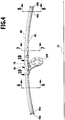
- the cross member 40 as in Fig. 4 represented projected on a transversely and perpendicular to the direction of travel 32 extending vertical plane with a concave subline 66 and provided with a convex top line 68, that is, that the cross member 40 between the mounting pad portions 46a and 46b extends upward, that is, starting from the Mounting land areas 46a and 46b up to a central area 70 progressively away from a roadway 72, so that the central area 70 has a greater distance from the roadway 72 than the end portions 44a and 44b with the mounting land areas 46a and 46b.
- center region 70 is arranged offset relative to the symmetrical to the longitudinal center plane 34 of the body 10 assembly mounting portions 46 a and 46 b opposite to the direction of travel 32 to the rear and above.
- the cross member is provided with an inverted U-shaped cross-sectional profile 80 formed by a front support web portion 82 and a rear support web portion 84 forming the two lateral legs of the U and joined by a central support web portion 86 which defines the center leg of the U forms.
- the support web areas 82 and 84 thereby run approximately parallel to one another, that is to say deviate from a parallel course at a maximum angle of 15 °, while the middle support web area 86 extends transversely to the front support web area 82 and the rear support web area 84, preferably approximately vertically to this.
- the support web areas 82, 84 and 86 enclose an inner space 88 which is open on a side 90 opposite the middle support web area, so that the cross member is suitable for production as a cast part.
- the inner space 88 extends without undercuts to the middle support web region 86, so that the cross member 40 is easily demoldable.
- the central support web portion 86 is arranged so that it extends substantially parallel to the direction of travel 32, that is with this a maximum angle of ⁇ 15 ° includes, while the front support web portion 82 and the rear support web portion 84 with its widthwise extension B, that is, extend substantially perpendicular to the direction of travel 32, that is with this include an angle in the range between 75 and 105 °.
- the support web regions 82 and 84 extend essentially vertically with their width extension and the support web region 86 essentially horizontally, that is to say they enclose an angle in the range between ⁇ 15 ° with a vertical or horizontal.
- the front support web portion 82 forms the concave contour 62, while the rear support web portion 84 forms the convex contour 64.
- front and rear support land portions 82 and 84 form the concave subline 66
- center support land portion 86 forms the convex top line 68.
- the cross-sectional profile 80 is formed varying with respect to its wall thickness W.
- the wall thickness W 2 of the cross-sectional profile 80 2 in the central region 70 is greater than the wall thickness W 3 of the cross-sectional profile 80 3 in the end region 44b, while conversely, the cross-sectional profile 80 2 in the central region 70 has a smaller extent, ie in particular one smaller extent of the central support web portion 86 than the cross-sectional profile 80 3 near the end portion 44, as in Fig. 8 shown, because the cross-sectional profile 80 3 has in particular a greater width extension B of the central support web portion 86.
- the ringan gleichdome 56 are not only formed on the mounting web portions 46, but also to at least the support web portions 82 and 84 and possibly also to the support web portion 86 and thus the cross member is an integrally manufactured as a cast part with integral stability, wherein the stability of minimized weight and the variation of the cross-sectional profiles 80 over the extension of the cross member 40 between the respective mounting web portion 46 and the central region 70 both in terms of the wall thickness W and the overall extent, in particular the width extent B of the central support web portion 86, contributes.
- a receptacle 100 for the pivot bearing unit 22 could be formed on the center region 70.
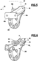
- the receptacle 100 is formed as a separate part, which, as in Fig. 6 and Fig. 10 shown connected to mounting terminal portions 102, 104 and 106, which are also integrally formed on the central region 70 of the cross member 40 and, for example, also ringan gleichdome 56 form, which are an integral part of the mounting pads 102, 104 and 106.
- the receptacle 100 in adaptation to the respective load-bearing unit, that is, for example, the respective pivot bearing unit 22 with the respective ball neck 24, form without a change in the cross member 40 is required in terms of its design when changing the load-bearing unit.
- the cross-sectional profile 80 ' is approximately E-shaped and thus has, in addition to the support web portions 82 and 84, a wide support web portion 92 which lies between the support web portions 82 and 84, while the central support web portion 86 interconnects the support web portions 82, 84 and 92 ,
- a third embodiment of a cross member according to the invention 40 "- shown in Fig. 12 - Is the cross-sectional profile 80 "U-shaped, that is just the reverse of the first embodiment, so that in this regard to the comments on the first embodiment can be fully incorporated by reference, however, in this cross-sectional profile 80" of the middle support web portion 86 in the installation position of the Cross member lower lying support bridge area is.
- a cross member according to the invention 40 '''- shown in Fig. 13 - Is the cross-sectional profile 80 '''formed so that this one has only the support web portion 82 and that the Support web portion 86 '''extends beyond both sides of the support web portion 82, so that the support web portion 86''' together with the support web portion 82 forms an approximately T-shaped cross-sectional shape.
- the cross member 40 "" is merely formed by the support web portions 84 and 86 and thus approximately angular or L-shaped.
- a support web region 94 extending at an angle thereto is also provided, so that the two support web regions 86 and 94 run approximately V-shaped, that is to say at an acute angle relative to one another.
Landscapes
- Engineering & Computer Science (AREA)
- Transportation (AREA)
- Mechanical Engineering (AREA)
- Body Structure For Vehicles (AREA)
Description
- Die Erfindung betrifft eine Heckanbauvorrichtung für Fahrzeuge mit einer Fahrzeugkarosserie, wobei die Heckanbauvorrichtung einen sich quer zu einer Längsmittelebene der Fahrzeugkarosserie erstreckenden Querträger umfasst, an welchem eine Lastaufnahmeeinheit montierbar ist und an Endbereichen des Querträgers gehaltene Seitenträger, mittels welchen der Querträger mit der Fahrzeugkarosserie verbindbar ist.
- Derartige Heckanbauvorrichtungen sind aus dem Stand der Technik bekannt, beispielsweise aus der
EP 1445 126 A1 , die den Oberbegriff des Anspruchs 1 zeigt. Bei diesen Heckanbauvorrichtungen ist der Querträger als geschweißtes Teil aus gewalztem oder gezogenem Profilmaterial ausgebildet, wobei die Form des Querträgers durch Biegen und/oder Schweißen und/oder zusätzliches Anbringen weiterer Elemente hergestellt wird. - Ein derart hergestellter Querträger lässt sich entweder nur schwer an komplexe Bauraumgeometrien anpassen oder ist aufwändig herzustellen.
- Der Erfindung liegt daher die Aufgabe zugrunde, eine Heckanbauvorrichtung für Fahrzeugkarosserien derart zu verbessern, dass diese einerseits einfach und kostengünstig herstellbar ist und andererseits an die jeweilige Bauraumgeometrie optimal anpassbar ist, insbesondere auch im Hinblick auf ihre Stabilitäts- und Steifigkeitseigenschaften.
- Diese Aufgabe wird bei einer Heckanbauvorrichtung der eingangs beschriebenen Art erfindungsgemäß durch die Merkmale des Anspruchs 1 gelöst. Der Vorteil der erfindungsgemäßen Lösung ist darin zu sehen, dass damit die Möglichkeit besteht, die Form des Querträgers optimal an die gegebenen Verhältnisse anzupassen und auch die gesamten am Querträger vorgesehenen Elemente bei der einstückigen Herstellung des Querträgers an diese anzuformen.
- Insbesondere lassen sich dabei die Tragstegbereiche des Querschnittsprofils optimal an die jeweiligen Lasten und dynamischen Beanspruchungen anpassen.
- Eine vorteilhafte Ausführungsform sieht dabei vor, dass das Querschnittsprofil U-ähnlich ist.
- Eine andere vorteilhafte Lösung sieht vor, dass das Querschnittsprofil T-ähnlich ausgebildet ist.
- Wieder eine andere Ausführungsform sieht vorteilhafterweise vor, dass das Querschnittsprofil L-ähnlich ausgebildet ist.
- Eine weitere alternative Ausführungsform sieht vor, dass das Querschnittsprofil V-ähnlich ausgebildet ist.
- Es besteht aber auch die Möglichkeit, in Abwandlung einer U-Form, das Querschnittsprofil ähnlich einem Kreissegment auszubilden.
- Um den Querträger gießtechnisch besonders einfach herstellen zu können, ist vorzugsweise vorgesehen, dass das Querschnittsprofil mindestens einen zu einer Seite hin offenen Profilinnenraum aufweist, vorzugsweise diesen Profilinnenraum bis auf die offene Seite umschließt.
- Besonders günstig ist es, insbesondere zum Entformen des gießtechnisch hergestellten Querträgers, wenn ausgehend von der offenen Seite der Profilinnenraum hinterschneidungsfrei ausgebildet ist.
- Noch vorteilhafter ist es dabei, wenn der Profilinnenraum zur offenen Seite hin sich erweiternd ausgebildet ist.
- Eine weitere besonders günstige Ausführungsform einer erfindungsgemäßen Heckanbauvorrichtung sieht vor, dass das Gussteil mindestens zwei quer zueinander verlaufende und sich von einem Endbereich zum anderen Endbereich erstreckende Tragstegbereiche umfasst.
- Eine derartige Konzeption des Gussteils aus mindestens zwei quer zueinander verlaufenden Tragstegbereichen schafft eine hohe Stabilität.
- Vorzugsweise ist dabei vorgesehen, dass mindestens einer der Tragstegbereiche mit seiner Breitenausdehnung im Wesentlichen quer zu einer Fahrtrichtung verläuft.
- Alternativ oder ergänzend hierzu ist vorgesehen, dass mindestens einer der Tragstegbereiche mit seiner Breitenausdehnung ungefähr parallel zur Fahrtrichtung verläuft.
- Noch vorteilhafter ist eine Lösung, bei welcher das Gussteil mindestens drei Tragstegbereiche aufweist, die sich von einem Endbereich zum anderen Endbereich erstrecken und insbesondere einstückig ineinander übergehen.
- Vorzugsweise können dabei von den mindestens drei Tragstegbereichen zwei Tragstegbereiche quer zu einem dritten Tragstegbereich verlaufen.
- Ferner ist vorteilhafterweise vorgesehen, dass die Tragstegbereiche durch Wandbereiche gebildet sind, deren Breitenausdehnung größer als eine Wanddicke derselben ist.
- Um insbesondere die bei einem erfindungsgemäß eingesetzten Querträger auftretenden Kräfte optimal aufnehmen zu können, ist dabei vorgesehen, dass der Querträger mindestens einen sich mit seiner Breitenausdehnung in ungefähr vertikaler Richtung erstreckenden Tragstegbereich aufweist.
- Ein derartiger Tragstegbereich des Querträgers schafft die Möglichkeit, besonders optimal Stützlasten aufzunehmen.
- Ferner ist vorzugsweise vorgesehen, dass der Querträger mindestens einen sich mit seiner Breitenausdehnung ungefähr in horizontaler Richtung erstreckenden Tragstegbereich aufweist und ein derartiger Tragstegbereich schafft die Möglichkeit, möglichst optimal Zuglasten aufzunehmen.
- Um den Querträger möglichst gewichtsparend ausbilden zu können, ist vorgesehen, dass das Querschnittsprofil zwischen einem Mittenbereich und den Endbereichen variiert, so dass durch die Variation des Querschnittsprofils eine optimale Anpassung an die auf den Querträger wirkenden Lasten erfolgen kann, ohne unnötig wiederum zum Gewicht des Querträgers beitragendes Material vorzusehen.
- Eine Möglichkeit einer derartigen Variation des Querschnittsprofils sieht vor, dass das Querschnittsprofil in dem Mittenbereich in einer ersten Richtung eine geringere Ausdehnung aufweist als in den Endbereichen.
- Die erste Richtung kann dabei vorzugsweise ungefähr parallel zur Fahrtrichtung verlaufen.
- Es ist aber auch denkbar, dass die erste Richtung quer zur Fahrtrichtung, das heißt ungefähr in vertikaler Richtung verläuft.
- Darüber hinaus sieht eine vorteilhafte Lösung vor, dass mindestens einer der Tragstegbereiche des Querschnittsprofils an den Endbereichen eine geringere Wandstärke aufweist als in dem Mittenbereich.
- Hinsichtlich der Gesamtform des Querträgers wurden bislang keine näheren Angaben gemacht.
- So sieht eine vorteilhafte Lösung vor, dass der Querträger in seiner Einbauanlage an der Karosserie zwischen den Endbereichen nach oben gekrümmt ist, das heißt, dass der Mittenbereich des Querträgers in größerem Abstand von einer Fahrbahn verläuft als die Endbereiche.
- Eine derartige Lösung hat den Vorteil, dass sich mit dieser Stützlasten optimal aufnehmen lassen.
- Eine andere vorteilhafte Lösung sieht vor, dass der Querträger in seiner Einbaulage an der Karosserie zwischen den Endbereichen entgegengesetzt zur Fahrtrichtung nach hinten gekrümmt ist.
- Eine derartige Lösung hat den Vorteil, dass sie sich optimal an Karosserieformen anpassen lässt, da die Karosserie in der Regel ebenfalls im Bereich ihrer Heckschürze nach hinten konvex verläuft, so dass damit der Einbauraum, der für den Querträger benötigt wird, minimiert werden kann.
- Grundsätzlich wäre es denkbar, den Querträger auch mit einer Aufnahme für eine Lastaufnahmeeinheit auszubilden.
- Dies würde jedoch eine komplizierte Gussformgebung erfordern, die kostenträchtig ist.
- Aus diesem Grund sieht eine vorteilhafte Lösung vor, dass an dem Querträger in dem Mittenbereich mindestens ein Montageanschlussbereich einstückig angeformt ist.
- Ein derartiger Montageanschlussbereich vereinfacht die Formgebung des Querträgers und schafft außerdem die Möglichkeit, unterschiedlichste Aufnahmen für Lastaufnahmeeinheiten an dem Querträger als Module zu montieren.
- Ein derartiger Montageanschlussbereich kann im einfachsten Fall als Durchbruch mit einer Anlagefläche ausgebildet sein, an welchen sich durch Schrauben oder andere Befestigungselemente eine Aufnahme fixieren lässt.
- Eine besonders günstige Lösung sieht jedoch vor, dass der Montageanschlussbereich einen Schraubanschlussbereich umfasst.
- In einem vorteilhaften Fall der Schraubanschlussbereich als Anschraubdom ausgebildet ist.
- Hinsichtlich der Verbindung des Querträgers mit den Seitenträgern wurden ebenfalls bislang keine näheren Angaben gemacht.
- Um die Seitenträger einfach montieren zu können, ist vorzugsweise vorgesehen, dass an den Endbereichen des Querträgers Anlageflächen für die Seitenträger einstückig angeformt sind.
- Derartige Anlageflächen für die Seitenträger sind dabei insbesondere von einstückig an die Tragstegbereiche angeformten Montagestegbereichen gebildet, welche einerseits ein Anlegen der Seitenträger an den Anlageflächen erlauben, andererseits so ausgebildet sind, dass an diesen die Seitenträger in einfacher Weise montierbar sind.
- Vorzugsweise ist dabei vorgesehen, dass die Montagestegbereiche sich quer zu den Tragstegbereichen erstrecken und diese dabei miteinander verbinden.
- Um insbesondere eine stabile Verbindung mit den Seitenträgern zu erlauben, ist vorzugsweise vorgesehen, dass sich die Montagestegbereiche über das Querschnittsprofil des Querträgers in den Endbereichen hinaus erstrecken und somit eine verbesserte Fixierung, insbesondere eine kippfeste Fixierung an den Seitenträgern erlauben.
- Insbesondere erstrecken sich dabei die Montagestegbereiche in Richtung der Seitenträger über das Querschnittsprofil des Querträgers hinaus.
- Um die Montagestegbereiche in einfacher Weise mit den Seitenträgern verbinden zu können, sind zusätzlich Schraubanschlussbereiche an diesen vorgesehen.
- Vorzugsweise sind dabei die Schraubanschlussbereiche als Schraubanschlussdome ausgebildet.
- Weitere Merkmale und Vorteile der Erfindung sind Gegenstand der nachfolgenden Beschreibung sowie der zeichnerischen Darstellung einiger Ausführungsbeispiele.
- In der Zeichnung zeigen:
- Fig. 1
- eine Seitenansicht eines Kraftfahrzeugs mit einer Fahrzeugkarosserie und einer Heckanbauvorrichtung für eine Anhängekupplung als Lastaufnahmeeinheit;
- Fig. 2
- eine perspektivische Darstellung eines ersten Ausführungsbeispiels der erfindungsgemäßen Heckanbauvorrichtung;
- Fig. 3
- eine Draufsicht in Richtung des Pfeils A in
Fig. 2 auf das erste Ausführungsbeispiel der erfindungsgemäßen Heckanbauvorrichtung; - Fig. 4
- eine Ansicht von hinten in Richtung des Pfeils B in
Fig. 2 ; - Fig. 5
- eine perspektivische Seitenansicht des erfindungsgemäßen als Gussteil ausgebildeten Querträgers mit einer an dem Querträger montierten Aufnahme für eine Lastaufnahmeeinheit;
- Fig. 6
- einen Schnitt längs Linie 6-6 in
Fig. 4 ; - Fig. 7
- einen Schnitt längs Linie 7-7 in
Fig. 4 ; - Fig. 8
- einen Schnitt längs Linie 8-8 in
Fig. 4 ; - Fig. 9
- einen Schnitt längs Linie 9-9 in
Fig. 3 ; - Fig. 10
- einen Schnitt längs Linie 10-10 in
Fig. 4 ; - Fig. 11
- einen Schnitt ähnlich
Fig. 8 durch ein zweites Ausführungsbeispiel einer erfindungsgemäßen Heckanbauvorrichtung; - Fig. 12
- einen Schnitt ähnlich
Fig. 8 durch ein drittes Ausführungsbeispiel einer erfindungsgemäßen Heckanbauvorrichtung; - Fig. 13
- einen Schnitt ähnlich
Fig. 8 durch ein viertes Ausführungsbeispiel einer erfindungsgemäßen Heckanbauvorrichtung; - Fig. 14
- einen Schnitt ähnlich
Fig. 8 durch ein fünftes Ausführungsbeispiel einer erfindungsgemäßen Heckanbauvorrichtung und - Fig. 15
- einen Schnitt ähnlich
Fig. 8 durch ein sechstes Ausführungsbeispiel einer erfindungsgemäßen Heckanbauvorrichtung. - Ein in
Fig. 1 dargestelltes Ausführungsbeispiel eines erfindungsgemäßen Kraftfahrzeugs umfasst eine Fahrzeugkarosserie 10, welche an ihrem Heckbereich 12, und zwar insbesondere im Bereich einer unteren Heckschürze 14 mit einer als Ganzes mit 20 bezeichneten Heckanbauvorrichtung versehen ist, an welcher beispielsweise mittels einer Schwenklagereinheit 22 ein als Ganzes mit 24 bezeichneter Kugelhals mit einem erste Ende 26 gehalten ist, welcher an einem zweiten Ende 28 eine als Ganzes mit 30 bezeichnete Kupplungskugel trägt. - Dabei umfasst die Heckanbauvorrichtung 20 einen sich quer zu einer Fahrtrichtung 32 und somit auch quer zu einer Längsmittelebene 34 erstreckenden Querträger 40, welcher mit Seitenträgern 42a und 42b an einem hinteren Karosseriebereich 36, der sich an die untere Heckschürze 14 anschließt, gehalten ist, wobei sich die Seitenträger 42a und 42b ungefähr in Fahrtrichtung erstrecken.
- Wie in
Fig. 2 dargestellt, liegt der Querträger 40 zwischen den Seitenteilen 42a und 42b, wobei Endbereiche 44a und 44b des Querträgers 40 mit den Seitenträgern 42 verbunden sind, wie nachfolgend noch im Detail beschrieben. - Der Querträger 40 umfasst an seinen Endbereichen 44a und 44b jeweils einen Montagestegbereich 46a und 46b, welche sich jeweils ungefähr parallel zu den Seitenträgern 42a und 42b erstreckt und jeweils Anlageflächen 48a und 48b aufweist, an welchen die Seitenträger 42 flächig anlegbar sind.
- Ferner umfassen die Montagestegbereiche 46a und 46b wie insbesondere in den
Fig. 7 und 8 erkennbar, Schraubanschlussbereiche 52 und 54, die als Schraubanschlussdome 56 ausgebildet sind und dabei jeweils ausgehend von dem entsprechenden Montagestegbereich 46 ein Sackloch 58 mit einem in dieses eingeschnittenen Schraubgewinde 60 bilden, wie inFig. 9 dargestellt. - Der sich zwischen den Montagestegbereichen 46a und 46b erstreckende Querträger 40 ist dabei - in Fahrtrichtung 32 gesehen - in Draufsicht, wie in
Fig. 3 dargestellt, auf seiner in Fahrtrichtung vorderen Seite mit einer konkaven Kontur 62 versehen und auf seiner in Fahrtrichtung 32 hinteren Seite mit einer konvexen Kontur 64, wobei die konkave Kontur 62 und die konvexe Kontur 64 nicht identisch sind, so dass deren Abstand im Verlauf der Erstreckung des Querträgers 40 von einem Montagestegbereich 46a, b zum anderen Montagestegbereich 46b, a variiert. - Darüber hinaus ist der Querträger 40, wie in
Fig. 4 dargestellt, in Projektion auf eine quer und senkrecht zur Fahrtrichtung 32 verlaufende vertikale Ebene mit einer konkaven Unterlinie 66 und mit einer konvexen Oberlinie 68 versehen, das heißt, dass der Querträger 40 zwischen den Montagestegbereichen 46a und 46b nach oben verläuft, das heißt ausgehend von den Montagestegbereichen 46a und 46b bis zu einem Mittenbereich 70 sich zunehmend von einer Fahrbahn 72 entfernt, so dass der Mittenbereich 70 einen größeren Abstand von der Fahrbahn 72 aufweist als die Endbereiche 44a und 44b mit den Montagestegbereichen 46a und 46b. - Insbesondere ist der Mittenbereich 70 relativ zu den symmetrisch zur Längsmittelebene 34 der Karosserie 10 angeordneten Montagestegbereichen 46a und 46b entgegengesetzt zur Fahrtrichtung 32 nach hinten und oben versetzt angeordnet.
- Wie in
Fig. 6 ,7 und 8 dargestellt, ist der Querträger mit einem umgekehrt U-förmigen Querschnittsprofil 80 versehen, welches durch einen vorderen Tragstegbereich 82 und einen hinteren Tragstegbereich 84 gebildet ist, die die beiden seitlichen Schenkel des U bilden und die durch einen mittleren Tragstegbereich 86 verbunden sind, welcher den Mittelschenkel des U bildet. - Die Tragstegbereiche 82 und 84 verlaufen dabei ungefähr parallel zueinander, das heißt sie weichen von einem parallelen Verlauf maximal mit einem Winkel von 15° voneinander ab, während der mittlere Tragstegbereich 86 quer zu dem vorderen Tragstegbereich 82 und dem hinteren Tragstegbereich 84 verläuft, vorzugsweise näherungsweise senkrecht zu diesen.
- Die Tragstegbereiche 82, 84 und 86 umschließen einen Innenraum 88 welcher auf einer dem mittleren Tragstegbereich gegenüberliegenden Seite 90 offen ist, so dass der Querträger sich zur Herstellung als Gussteil eignet.
- Insbesondere erstreckt sich der Innenraum 88 ausgehend von der offenen Seite 90 hinterschneidungsfrei bis zum mittleren Tragstegbereich 86, so dass der Querträger 40 leicht entformbar ist.
- Beispielsweise ist der mittlere Tragstegbereich 86 so angeordnet, dass er sich im Wesentlichen parallel zur Fahrtrichtung 32 erstreckt, das heißt mit diesem maximal einen Winkel von ± 15° einschließt, während sich der vordere Tragstegbereich 82 und der hintere Tragstegbereich 84 mit ihrer Breitenausdehnung B quer, das heißt im Wesentlichen senkrecht zu der Fahrtrichtung 32 erstrecken, das heißt mit dieser einen Winkel im Bereich zwischen 75 und 105° einschließen.
- Insbesondere verlaufen die Tragstegbereiche 82 und 84 mit ihrer Breitenausdehnung im Wesentlichen vertikal und der Tragstegbereich 86 im Wesentlichen horizontal, das heißt sie schließen mit einer Vertikalen bzw. Horizontalen einen Winkel im Bereich zwischen ± 15° ein.
- Bei einer derartigen Ausführung des Querträgers 40 gemäß dem ersten Ausführungsbeispiel bildet der vordere Tragstegbereich 82 die konkave Kontur 62, während der hintere Tragstegbereich 84 die konvexe Kontur 64 bildet.
- Ferner bilden der vordere und der hintere Tragstegbereich 82 und 84 die konkave Unterlinie 66 und der mittlere Tragstegbereich 86 bildet die konvexe Oberlinie 68.
- Dabei ist das Querschnittsprofil 80 hinsichtlich seiner Wanddicke W variierend ausgebildet.
- Beispielsweise liegt die Wanddicke W2 des Querschnittsprofils 802 im Mittenbereich 70 bei Werten, die größer sind als die Wanddicke W3 des Querschnittsprofils 803 in dem Endbereich 44b, während umgekehrt das Querschnittsprofil 802 im Mittenbereich 70 eine geringere Ausdehnung, das heißt insbesondere eine geringere Ausdehnung des mittleren Tragstegbereichs 86 aufweist als das Querschnittsprofil 803 nahe des Endbereichs 44, wie in
Fig. 8 dargestellt, denn das Querschnittsprofil 803 weist insbesondere eine größere Breitenausdehnung B des mittleren Tragstegbereichs 86 auf. - Wie insbesondere in
Fig. 7 und 8 erkennbar, bildet der Querträger 40 mit den Tragstegbereichen 82, 84 und 86 sowie den Montagestegbereichen 46 und den Schraubanschlussbereichen 52 und 54 insbesondere mit den Schraubanschlussdomen 56 ein einstückig als Gussteil hergestelltes Teil, wobei die Schraubanschlussdome 56 nicht nur an die Montagestegbereiche 46 angeformt sind, sondern auch zumindest an die Tragstegbereiche 82 und 84 und gegebenenfalls auch an den Tragstegbereich 86 und somit stellt der Querträger ein einstückig als Gussteil hergestelltes Teil mit integraler Stabilität dar, wobei zur Stabilität bei minimiertem Gewicht auch die Variation der Querschnittsprofile 80 über die Ausdehnung des Querträgers 40 zwischen dem jeweiligen Montagestegbereich 46 und dem Mittenbereich 70 sowohl hinsichtlich der Wandstärke W als auch der Gesamtausdehnung, insbesondere der Breitenausdehnung B des mittleren Tragstegbereichs 86, beiträgt. - An dem Mittenbereich 70 könnte beispielsweise eine Aufnahme 100 für die Schwenklagereinheit 22 angeformt sein.
- Weit vorteilhafter ist es jedoch, wenn die Aufnahme 100 als separates Teil ausgebildet ist, welches, wie in
Fig. 6 undFig. 10 dargestellt, mit Montageanschlussbereichen 102, 104 und 106 verbunden ist, die ebenfalls einstückig an den Mittenbereich 70 des Querträgers 40 angeformt sind und beispielsweise ebenfalls Schraubanschlussdome 56 bilden, die integraler Bestandteil der Montageanschlussbereiche 102, 104 und 106 sind. - Damit lässt sich die Aufnahme 100 in Anpassung an die jeweilige Lastaufnahmeeinheit, das heißt beispielsweise die jeweilige Schwenklagereinheit 22 mit dem jeweiligen Kugelhals 24, ausbilden, ohne dass bei einer Änderung der Lastaufnahmeeinheit eine Änderung des Querträgers 40 hinsichtlich seiner Formgestaltung erforderlich ist.
- Bei einem zweiten Ausführungsbeispiel eines erfindungsgemäßen Querträgers 40', dargestellt in
Fig. 11 , ist das Querschnittsprofil 80' ungefähr E-förmig ausgebildet und weist somit zusätzlich zu den Tragstegbereichen 82 und 84 einen weite4ren Tragstegbereich 92 auf, der zwischen den Tragstegbereichen 82 und 84 liegt, während der mittlere Tragstegbereich 86 die Tragstegbereiche 82, 84 und 92 miteinander verbindet. - Bei einem dritten Ausführungsbeispiel eines erfindungsgemäßen Querträgers 40" - dargestellt in
Fig. 12 - ist das Querschnittsprofil 80" U-förmig ausgebildet, das heißt genau umgekehrt wie das erste Ausführungsbeispiel, so dass diesbezüglich auf die Ausführungen zum ersten Ausführungsbeispiel vollinhaltlich Bezug genommen werden kann, wobei allerdings bei diesem Querschnittsprofil 80" der mittlere Tragstegbereich 86 der in Einbaulage des Querträgers unten liegende Tragstegbereich ist. - Bei einem vierten Ausführungsbeispiel eines erfindungsgemäßen Querträgers 40''' - dargestellt in
Fig. 13 - ist das Querschnittsprofil 80''' so ausgebildet, dass dieses einen nur den Tragstegbereich 82 aufweist und dass der Tragstegbereich 86''' sich beiderseits über den Tragstegbereich 82 hinaus erstreckt, so dass der Tragstegbereich 86''' zusammen mit dem Tragstegbereich 82 eine ungefähr T-förmige Querschnittsform bildet. - Bei einem fünften Ausführungsbeispiel des erfindungsgemäßen Querträgers 40"", dargestellt in
Fig. 14 , ist der Querträger 40"" lediglich durch die Tragstegbereiche 84 und 86 gebildet und somit ungefähr winkel- oder L-förmig. - Bei einem sechsten Ausführungsbeispiel eines erfindungsgemäßen Querträgers 40""', dargestellt in
Fig. 15 , ist zusätzlich zum Tragstegbereich 86 noch ein schräg zu diesem verlaufender Tragstegbereich 94 vorgesehen, so dass die beiden Tragstegbereiche 86 und 94 ungefähr V-förmig, das heißt mit einem spitzen Winkel relativ zueinander verlaufen. - Sind bei dem zweiten bis sechsten Ausführungsbeispiel all diejenigen Teile des jeweiligen Querträgers 40, die mit denen des ersten Ausführungsbeispiels identisch sind, mit denselben Bezugszeichen versehen, so dass hinsichtlich der Erläuterung derselben vollinhaltlich zu den Ausführungen im Zusammenhang mit dem ersten Ausführungsbeispiel Bezug genommen werden kann.
Claims (13)
- Heckanbauvorrichtung für eine Fahrzeugkarosserie umfassend einen sich quer zu einer Längsmittelebene (34) der Fahrzeugkarosserie (10) erstreckenden Querträger (40), an welchem eine Lastaufnahmeeinheit (20, 22) montiert ist, und an Endbereichen (44) des Querträgers (40) gehaltene Seitenträger (42), mittels welchen der Querträger (40) mit der Fahrzeugkarosserie (10) verbunden wird,
dadurch gekennzeichnet, dass der Querträger als Gussteil ausgebildet ist, dass das Gussteil aus miteinander einstückig verbundenen Tragstegbereichen (82, 84, 86, 88, 89) gebildet ist, die ein Querschnittsprofil (80) des Gussteils ergeben, welches zwischen dem Mittenbereich (70) und den Endbereichen (44) zu einer Seite (90) hin offen ist, und dass das Querschnittsprofil (80) zwischen einem Mittenbereich (70) und den Endbereichen (44) variiert, dass das Querschnittsprofil (80) in dem Mittenbereich (70) in einer ersten Richtung eine geringere Ausdehnung aufweist als in den Endbereichen (44). - Heckanbauvorrichtung nach einem der voranstehenden Ansprüche,
dadurch gekennzeichnet, dass das Querschnittsprofil (80) mindestens einen zu einer Seite (90) hin offenen Profilinnenraum (88) aufweist. - Heckanbauvorrichtung nach Anspruch 2, dadurch gekennzeichnet, dass ausgehend von der offenen Seite (90) der Profilinnenraum (88) hinterschneidungsfrei ausgebildet ist.
- Heckanbauvorrichtung nach einem der voranstehenden Ansprüche,
dadurch gekennzeichnet, dass sich der Profilinnenraum (88) zur offenen Seite (90) hin sich erweiternd ausgebildet ist. - Heckanbauvorrichtung nach einem der voranstehenden Ansprüche, dadurch gekennzeichnet, dass das Gussteil mindestens zwei quer zueinander verlaufende und sich von einem Endbereich (44) zum anderen Endbereich (44) erstreckende Tragstegbereiche (82, 84, 86) umfasst.
- Heckanbauvorrichtung nach einem der voranstehenden Ansprüche, dadurch gekennzeichnet, dass das Gussteil mindestens drei Tragstegbereiche (82, 84, 86) aufweist, die sich von einem Endbereich (44) zum anderen Endbereich (44) erstrecken.
- Heckanbauvorrichtung nach einem der voranstehenden Ansprüche, dadurch gekennzeichnet, dass die Tragstegbereiche (82, 84, 86) durch Wandbereiche gebildet sind, deren Breitenausdehnung größer ist als eine Wanddicke derselben.
- Heckanbauvorrichtung nach einem der voranstehenden Ansprüche, dadurch gekennzeichnet, dass mindestens einer der Tragstegbereiche (82, 84, 86) des Querschnittsprofils (80) an den Endbereichen (44) eine geringere Wandstärke aufweist als in dem Mittenbereich (70).
- Heckanbauvorrichtung nach einem der voranstehenden Ansprüche, dadurch gekennzeichnet, dass der Querträger (40) in seiner Einbaulage an der Karosserie (10) zwischen den Endbereichen (44) nach oben gekrümmt ist.
- Heckanbauvorrichtung nach einem der voranstehenden Ansprüche, dadurch gekennzeichnet, dass der Querträger (409 in seiner Einbaulage an der Karosserie (10) zwischen den Endbereichen (44) entgegengesetzt zur Fahrtrichtung (32) nach hinten gekrümmt ist.
- Heckanbauvorrichtung nach einem der voranstehenden Ansprüche, dadurch gekennzeichnet, dass in dem Mittenbereich (70) mindestens ein Montageanschlussbereich (102, 104, 106) einstückig angeformt ist.
- Heckanbauvorrichtung nach einem der voranstehenden Ansprüche, dadurch gekennzeichnet, dass an den Endbereichen (44) des Querträgers (40) Anlageflächen (48) für die Seitenträger (42) einstückig angeformt sind.
- Heckanbauvorrichtung nach einem der voranstehenden Ansprüche, dadurch gekennzeichnet, dass die Anlageflächen (48) von einstückig an die Tragstegbereiche (82, 84, 86) angeformten Montagestegbereichen (46) gebildet sind.
Applications Claiming Priority (1)
| Application Number | Priority Date | Filing Date | Title |
|---|---|---|---|
| DE102010029394A DE102010029394A1 (de) | 2010-05-27 | 2010-05-27 | Heckanbauvorrichtung |
Publications (2)
| Publication Number | Publication Date |
|---|---|
| EP2390119A1 EP2390119A1 (de) | 2011-11-30 |
| EP2390119B1 true EP2390119B1 (de) | 2018-07-04 |
Family
ID=44117924
Family Applications (1)
| Application Number | Title | Priority Date | Filing Date |
|---|---|---|---|
| EP11167403.2A Active EP2390119B1 (de) | 2010-05-27 | 2011-05-25 | Heckanbauvorrichtung |
Country Status (2)
| Country | Link |
|---|---|
| EP (1) | EP2390119B1 (de) |
| DE (1) | DE102010029394A1 (de) |
Families Citing this family (1)
| Publication number | Priority date | Publication date | Assignee | Title |
|---|---|---|---|---|
| DE102012015244A1 (de) * | 2012-06-01 | 2013-12-05 | Westfalia-Automotive Gmbh | Trägeranordnung für eine Anhängekupplung mit einem Urform-Tragbauteil |
Citations (1)
| Publication number | Priority date | Publication date | Assignee | Title |
|---|---|---|---|---|
| EP1445126A1 (de) * | 2003-02-04 | 2004-08-11 | Vbg Ab | Anhängerkupplung und Zugtraverse |
Family Cites Families (7)
| Publication number | Priority date | Publication date | Assignee | Title |
|---|---|---|---|---|
| US6010142A (en) * | 1994-08-18 | 2000-01-04 | Reese Products, Inc. | Cast ductile iron hitch bar |
| US6348112B1 (en) * | 2000-01-05 | 2002-02-19 | Visteon Global Technologies, Inc. | Method for manufacturing a trailer hitch assembly |
| DE10061491C1 (de) * | 2000-12-09 | 2002-04-18 | Porsche Ag | Anhängezugvorrichtung |
| US6402179B1 (en) * | 2001-05-10 | 2002-06-11 | Ford Global Tech., Inc. | Lightweight towing cross member for a vehicle |
| SE523794C2 (sv) * | 2002-07-10 | 2004-05-18 | Monoflex Sweden Ab | Dragbalkskonstruktion |
| DE102004008740A1 (de) * | 2003-11-19 | 2005-06-23 | Alcan Technology & Management Ag | Querträger für Stoßfängersysteme |
| WO2006065117A1 (en) * | 2004-12-14 | 2006-06-22 | Thule Towing Systems B.V. | Load carrier for passenger cars |
-
2010
- 2010-05-27 DE DE102010029394A patent/DE102010029394A1/de not_active Ceased
-
2011
- 2011-05-25 EP EP11167403.2A patent/EP2390119B1/de active Active
Patent Citations (1)
| Publication number | Priority date | Publication date | Assignee | Title |
|---|---|---|---|---|
| EP1445126A1 (de) * | 2003-02-04 | 2004-08-11 | Vbg Ab | Anhängerkupplung und Zugtraverse |
Also Published As
| Publication number | Publication date |
|---|---|
| DE102010029394A1 (de) | 2011-12-01 |
| EP2390119A1 (de) | 2011-11-30 |
Similar Documents
| Publication | Publication Date | Title |
|---|---|---|
| DE19536460B4 (de) | Teilrahmen für ein Fahrzeug | |
| DE69423972T2 (de) | Endabschnitt eines rahmenteils für ein fahrzeug | |
| DE10300393B3 (de) | Rahmenvorderteil für ein Nutzfahrzeug | |
| EP2277722A2 (de) | Anhängekupplung für Kraftfahrzeuge | |
| DE202009015406U1 (de) | Fahrmischer | |
| EP2399782B1 (de) | Traggestell zur seitlichen Befestigung von Anbauteilen an einem Längsträger einer Nutzfahrzeug-Tragstruktur | |
| EP2360081B1 (de) | Fahrzeugkarosserieaufbau im Bereich zwischen Federbeinaufnahmen und Scheibenquerträger sowie zugeordnetes Fertigungsverfahren | |
| EP4339036B1 (de) | Kraftfahrzeug mit stossfängeranordnung | |
| EP2759422B1 (de) | Anhängekupplung | |
| EP1270378B1 (de) | Fahrgestell für Fahrzeuganhänger | |
| DE102006014979A1 (de) | Tragstruktur für ein Kraftfahrzeug | |
| DE19857321A1 (de) | Kupplungsträger | |
| DE102012022613B4 (de) | Anhängesystem für ein Kraftfahrzeug | |
| EP3517328A1 (de) | Anhängekupplung | |
| EP3459898B1 (de) | Unterteil für eine klemmvorrichtung | |
| EP2986459B1 (de) | Längslenker | |
| DE102005055396A1 (de) | Drehmomentquerträger | |
| EP2390119A1 (de) | Heckanbauvorrichtung | |
| DE29518575U1 (de) | Anhänger für Personenkraftwagen | |
| DE102006044402A1 (de) | Achsaufhängung für eine längslenkergeführte Fahrzeugachse | |
| EP2671776B1 (de) | Tragbock für eine einen Querträger umfassende Tragkonstruktion für ein Kraftfahrzeug | |
| DE102006009857B3 (de) | Scheuerplatten-Rahmenelement für einen Aufliegeranhänger | |
| EP0065623A1 (de) | Flanschkonstruktion für die Schraubverbindung zwischen einem Anhänger-Fahrgestell und dem Rahmen des Anhänger-Aufbaues | |
| DE10314035B4 (de) | Scharniersäule einer Kraftwagenkarosserie, insbesondere einer Karosserie für einen Personenkraftwagen | |
| DE102004001747A1 (de) | Fahrzeugkarosserie mit einer Rohbaustruktur |
Legal Events
| Date | Code | Title | Description |
|---|---|---|---|
| AK | Designated contracting states |
Kind code of ref document: A1 Designated state(s): AL AT BE BG CH CY CZ DE DK EE ES FI FR GB GR HR HU IE IS IT LI LT LU LV MC MK MT NL NO PL PT RO RS SE SI SK SM TR |
|
| AX | Request for extension of the european patent |
Extension state: BA ME |
|
| PUAI | Public reference made under article 153(3) epc to a published international application that has entered the european phase |
Free format text: ORIGINAL CODE: 0009012 |
|
| 17P | Request for examination filed |
Effective date: 20120524 |
|
| 17Q | First examination report despatched |
Effective date: 20141029 |
|
| RAP1 | Party data changed (applicant data changed or rights of an application transferred) |
Owner name: SCAMBIA HOLDINGS CYPRUS LIMITED |
|
| REG | Reference to a national code |
Ref country code: DE Ref legal event code: R079 Ref document number: 502011014398 Country of ref document: DE Free format text: PREVIOUS MAIN CLASS: B60D0001140000 Ipc: B60D0001480000 |
|
| RIC1 | Information provided on ipc code assigned before grant |
Ipc: B60D 1/48 20060101AFI20170522BHEP |
|
| GRAP | Despatch of communication of intention to grant a patent |
Free format text: ORIGINAL CODE: EPIDOSNIGR1 |
|
| STAA | Information on the status of an ep patent application or granted ep patent |
Free format text: STATUS: GRANT OF PATENT IS INTENDED |
|
| INTG | Intention to grant announced |
Effective date: 20170703 |
|
| GRAS | Grant fee paid |
Free format text: ORIGINAL CODE: EPIDOSNIGR3 |
|
| GRAJ | Information related to disapproval of communication of intention to grant by the applicant or resumption of examination proceedings by the epo deleted |
Free format text: ORIGINAL CODE: EPIDOSDIGR1 |
|
| GRAL | Information related to payment of fee for publishing/printing deleted |
Free format text: ORIGINAL CODE: EPIDOSDIGR3 |
|
| STAA | Information on the status of an ep patent application or granted ep patent |
Free format text: STATUS: EXAMINATION IS IN PROGRESS |
|
| INTC | Intention to grant announced (deleted) | ||
| GRAP | Despatch of communication of intention to grant a patent |
Free format text: ORIGINAL CODE: EPIDOSNIGR1 |
|
| STAA | Information on the status of an ep patent application or granted ep patent |
Free format text: STATUS: GRANT OF PATENT IS INTENDED |
|
| RAP1 | Party data changed (applicant data changed or rights of an application transferred) |
Owner name: BOSAL ACPS HOLDING 2 B.V. |
|
| INTG | Intention to grant announced |
Effective date: 20180104 |
|
| GRAA | (expected) grant |
Free format text: ORIGINAL CODE: 0009210 |
|
| STAA | Information on the status of an ep patent application or granted ep patent |
Free format text: STATUS: THE PATENT HAS BEEN GRANTED |
|
| AK | Designated contracting states |
Kind code of ref document: B1 Designated state(s): AL AT BE BG CH CY CZ DE DK EE ES FI FR GB GR HR HU IE IS IT LI LT LU LV MC MK MT NL NO PL PT RO RS SE SI SK SM TR |
|
| REG | Reference to a national code |
Ref country code: GB Ref legal event code: FG4D Free format text: NOT ENGLISH |
|
| REG | Reference to a national code |
Ref country code: CH Ref legal event code: EP |
|
| REG | Reference to a national code |
Ref country code: AT Ref legal event code: REF Ref document number: 1014109 Country of ref document: AT Kind code of ref document: T Effective date: 20180715 |
|
| REG | Reference to a national code |
Ref country code: IE Ref legal event code: FG4D Free format text: LANGUAGE OF EP DOCUMENT: GERMAN |
|
| REG | Reference to a national code |
Ref country code: DE Ref legal event code: R096 Ref document number: 502011014398 Country of ref document: DE |
|
| REG | Reference to a national code |
Ref country code: NL Ref legal event code: MP Effective date: 20180704 |
|
| REG | Reference to a national code |
Ref country code: LT Ref legal event code: MG4D |
|
| PG25 | Lapsed in a contracting state [announced via postgrant information from national office to epo] |
Ref country code: NL Free format text: LAPSE BECAUSE OF FAILURE TO SUBMIT A TRANSLATION OF THE DESCRIPTION OR TO PAY THE FEE WITHIN THE PRESCRIBED TIME-LIMIT Effective date: 20180704 |
|
| PG25 | Lapsed in a contracting state [announced via postgrant information from national office to epo] |
Ref country code: SE Free format text: LAPSE BECAUSE OF FAILURE TO SUBMIT A TRANSLATION OF THE DESCRIPTION OR TO PAY THE FEE WITHIN THE PRESCRIBED TIME-LIMIT Effective date: 20180704 Ref country code: BG Free format text: LAPSE BECAUSE OF FAILURE TO SUBMIT A TRANSLATION OF THE DESCRIPTION OR TO PAY THE FEE WITHIN THE PRESCRIBED TIME-LIMIT Effective date: 20181004 Ref country code: IS Free format text: LAPSE BECAUSE OF FAILURE TO SUBMIT A TRANSLATION OF THE DESCRIPTION OR TO PAY THE FEE WITHIN THE PRESCRIBED TIME-LIMIT Effective date: 20181104 Ref country code: PL Free format text: LAPSE BECAUSE OF FAILURE TO SUBMIT A TRANSLATION OF THE DESCRIPTION OR TO PAY THE FEE WITHIN THE PRESCRIBED TIME-LIMIT Effective date: 20180704 Ref country code: GR Free format text: LAPSE BECAUSE OF FAILURE TO SUBMIT A TRANSLATION OF THE DESCRIPTION OR TO PAY THE FEE WITHIN THE PRESCRIBED TIME-LIMIT Effective date: 20181005 Ref country code: LT Free format text: LAPSE BECAUSE OF FAILURE TO SUBMIT A TRANSLATION OF THE DESCRIPTION OR TO PAY THE FEE WITHIN THE PRESCRIBED TIME-LIMIT Effective date: 20180704 Ref country code: RS Free format text: LAPSE BECAUSE OF FAILURE TO SUBMIT A TRANSLATION OF THE DESCRIPTION OR TO PAY THE FEE WITHIN THE PRESCRIBED TIME-LIMIT Effective date: 20180704 Ref country code: FI Free format text: LAPSE BECAUSE OF FAILURE TO SUBMIT A TRANSLATION OF THE DESCRIPTION OR TO PAY THE FEE WITHIN THE PRESCRIBED TIME-LIMIT Effective date: 20180704 Ref country code: CZ Free format text: LAPSE BECAUSE OF FAILURE TO SUBMIT A TRANSLATION OF THE DESCRIPTION OR TO PAY THE FEE WITHIN THE PRESCRIBED TIME-LIMIT Effective date: 20180704 Ref country code: NO Free format text: LAPSE BECAUSE OF FAILURE TO SUBMIT A TRANSLATION OF THE DESCRIPTION OR TO PAY THE FEE WITHIN THE PRESCRIBED TIME-LIMIT Effective date: 20181004 |
|
| PG25 | Lapsed in a contracting state [announced via postgrant information from national office to epo] |
Ref country code: HR Free format text: LAPSE BECAUSE OF FAILURE TO SUBMIT A TRANSLATION OF THE DESCRIPTION OR TO PAY THE FEE WITHIN THE PRESCRIBED TIME-LIMIT Effective date: 20180704 Ref country code: LV Free format text: LAPSE BECAUSE OF FAILURE TO SUBMIT A TRANSLATION OF THE DESCRIPTION OR TO PAY THE FEE WITHIN THE PRESCRIBED TIME-LIMIT Effective date: 20180704 Ref country code: ES Free format text: LAPSE BECAUSE OF FAILURE TO SUBMIT A TRANSLATION OF THE DESCRIPTION OR TO PAY THE FEE WITHIN THE PRESCRIBED TIME-LIMIT Effective date: 20180704 Ref country code: AL Free format text: LAPSE BECAUSE OF FAILURE TO SUBMIT A TRANSLATION OF THE DESCRIPTION OR TO PAY THE FEE WITHIN THE PRESCRIBED TIME-LIMIT Effective date: 20180704 |
|
| REG | Reference to a national code |
Ref country code: DE Ref legal event code: R097 Ref document number: 502011014398 Country of ref document: DE |
|
| PG25 | Lapsed in a contracting state [announced via postgrant information from national office to epo] |
Ref country code: RO Free format text: LAPSE BECAUSE OF FAILURE TO SUBMIT A TRANSLATION OF THE DESCRIPTION OR TO PAY THE FEE WITHIN THE PRESCRIBED TIME-LIMIT Effective date: 20180704 Ref country code: IT Free format text: LAPSE BECAUSE OF FAILURE TO SUBMIT A TRANSLATION OF THE DESCRIPTION OR TO PAY THE FEE WITHIN THE PRESCRIBED TIME-LIMIT Effective date: 20180704 Ref country code: EE Free format text: LAPSE BECAUSE OF FAILURE TO SUBMIT A TRANSLATION OF THE DESCRIPTION OR TO PAY THE FEE WITHIN THE PRESCRIBED TIME-LIMIT Effective date: 20180704 |
|
| PLBE | No opposition filed within time limit |
Free format text: ORIGINAL CODE: 0009261 |
|
| STAA | Information on the status of an ep patent application or granted ep patent |
Free format text: STATUS: NO OPPOSITION FILED WITHIN TIME LIMIT |
|
| REG | Reference to a national code |
Ref country code: DE Ref legal event code: R082 Ref document number: 502011014398 Country of ref document: DE Representative=s name: HOEGER, STELLRECHT & PARTNER PATENTANWAELTE MB, DE Ref country code: DE Ref legal event code: R081 Ref document number: 502011014398 Country of ref document: DE Owner name: ACPS AUTOMOTIVE GMBH, DE Free format text: FORMER OWNER: BOSAL ACPS HOLDING 2 B.V., VIANEN, NL |
|
| PG25 | Lapsed in a contracting state [announced via postgrant information from national office to epo] |
Ref country code: SK Free format text: LAPSE BECAUSE OF FAILURE TO SUBMIT A TRANSLATION OF THE DESCRIPTION OR TO PAY THE FEE WITHIN THE PRESCRIBED TIME-LIMIT Effective date: 20180704 Ref country code: SM Free format text: LAPSE BECAUSE OF FAILURE TO SUBMIT A TRANSLATION OF THE DESCRIPTION OR TO PAY THE FEE WITHIN THE PRESCRIBED TIME-LIMIT Effective date: 20180704 Ref country code: DK Free format text: LAPSE BECAUSE OF FAILURE TO SUBMIT A TRANSLATION OF THE DESCRIPTION OR TO PAY THE FEE WITHIN THE PRESCRIBED TIME-LIMIT Effective date: 20180704 |
|
| 26N | No opposition filed |
Effective date: 20190405 |
|
| PG25 | Lapsed in a contracting state [announced via postgrant information from national office to epo] |
Ref country code: SI Free format text: LAPSE BECAUSE OF FAILURE TO SUBMIT A TRANSLATION OF THE DESCRIPTION OR TO PAY THE FEE WITHIN THE PRESCRIBED TIME-LIMIT Effective date: 20180704 |
|
| REG | Reference to a national code |
Ref country code: CH Ref legal event code: PL |
|
| PG25 | Lapsed in a contracting state [announced via postgrant information from national office to epo] |
Ref country code: CH Free format text: LAPSE BECAUSE OF NON-PAYMENT OF DUE FEES Effective date: 20190531 Ref country code: LI Free format text: LAPSE BECAUSE OF NON-PAYMENT OF DUE FEES Effective date: 20190531 Ref country code: MC Free format text: LAPSE BECAUSE OF FAILURE TO SUBMIT A TRANSLATION OF THE DESCRIPTION OR TO PAY THE FEE WITHIN THE PRESCRIBED TIME-LIMIT Effective date: 20180704 |
|
| REG | Reference to a national code |
Ref country code: BE Ref legal event code: MM Effective date: 20190531 |
|
| PG25 | Lapsed in a contracting state [announced via postgrant information from national office to epo] |
Ref country code: LU Free format text: LAPSE BECAUSE OF NON-PAYMENT OF DUE FEES Effective date: 20190525 |
|
| PG25 | Lapsed in a contracting state [announced via postgrant information from national office to epo] |
Ref country code: TR Free format text: LAPSE BECAUSE OF FAILURE TO SUBMIT A TRANSLATION OF THE DESCRIPTION OR TO PAY THE FEE WITHIN THE PRESCRIBED TIME-LIMIT Effective date: 20180704 |
|
| PG25 | Lapsed in a contracting state [announced via postgrant information from national office to epo] |
Ref country code: IE Free format text: LAPSE BECAUSE OF NON-PAYMENT OF DUE FEES Effective date: 20190525 |
|
| PG25 | Lapsed in a contracting state [announced via postgrant information from national office to epo] |
Ref country code: BE Free format text: LAPSE BECAUSE OF NON-PAYMENT OF DUE FEES Effective date: 20190531 |
|
| PG25 | Lapsed in a contracting state [announced via postgrant information from national office to epo] |
Ref country code: PT Free format text: LAPSE BECAUSE OF FAILURE TO SUBMIT A TRANSLATION OF THE DESCRIPTION OR TO PAY THE FEE WITHIN THE PRESCRIBED TIME-LIMIT Effective date: 20181105 |
|
| PG25 | Lapsed in a contracting state [announced via postgrant information from national office to epo] |
Ref country code: CY Free format text: LAPSE BECAUSE OF FAILURE TO SUBMIT A TRANSLATION OF THE DESCRIPTION OR TO PAY THE FEE WITHIN THE PRESCRIBED TIME-LIMIT Effective date: 20180704 |
|
| PG25 | Lapsed in a contracting state [announced via postgrant information from national office to epo] |
Ref country code: HU Free format text: LAPSE BECAUSE OF FAILURE TO SUBMIT A TRANSLATION OF THE DESCRIPTION OR TO PAY THE FEE WITHIN THE PRESCRIBED TIME-LIMIT; INVALID AB INITIO Effective date: 20110525 Ref country code: MT Free format text: LAPSE BECAUSE OF FAILURE TO SUBMIT A TRANSLATION OF THE DESCRIPTION OR TO PAY THE FEE WITHIN THE PRESCRIBED TIME-LIMIT Effective date: 20180704 |
|
| REG | Reference to a national code |
Ref country code: AT Ref legal event code: PC Ref document number: 1014109 Country of ref document: AT Kind code of ref document: T Owner name: ACPS AUTOMOTIVE GMBH, DE Effective date: 20211001 |
|
| REG | Reference to a national code |
Ref country code: GB Ref legal event code: 732E Free format text: REGISTERED BETWEEN 20220224 AND 20220302 |
|
| PG25 | Lapsed in a contracting state [announced via postgrant information from national office to epo] |
Ref country code: MK Free format text: LAPSE BECAUSE OF FAILURE TO SUBMIT A TRANSLATION OF THE DESCRIPTION OR TO PAY THE FEE WITHIN THE PRESCRIBED TIME-LIMIT Effective date: 20180704 |
|
| REG | Reference to a national code |
Ref country code: DE Ref legal event code: R081 Ref document number: 502011014398 Country of ref document: DE Owner name: ACPS AUTOMOTIVE GMBH, DE Free format text: FORMER OWNER: ACPS AUTOMOTIVE GMBH, 71706 MARKGROENINGEN, DE |
|
| P01 | Opt-out of the competence of the unified patent court (upc) registered |
Effective date: 20230517 |
|
| PGFP | Annual fee paid to national office [announced via postgrant information from national office to epo] |
Ref country code: DE Payment date: 20250521 Year of fee payment: 15 |
|
| PGFP | Annual fee paid to national office [announced via postgrant information from national office to epo] |
Ref country code: GB Payment date: 20250521 Year of fee payment: 15 |
|
| PGFP | Annual fee paid to national office [announced via postgrant information from national office to epo] |
Ref country code: FR Payment date: 20250528 Year of fee payment: 15 |
|
| PGFP | Annual fee paid to national office [announced via postgrant information from national office to epo] |
Ref country code: AT Payment date: 20250522 Year of fee payment: 15 |