EP2390026A2 - Forming a cast component with agitation - Google Patents
Forming a cast component with agitation Download PDFInfo
- Publication number
- EP2390026A2 EP2390026A2 EP11250099A EP11250099A EP2390026A2 EP 2390026 A2 EP2390026 A2 EP 2390026A2 EP 11250099 A EP11250099 A EP 11250099A EP 11250099 A EP11250099 A EP 11250099A EP 2390026 A2 EP2390026 A2 EP 2390026A2
- Authority
- EP
- European Patent Office
- Prior art keywords
- investment mold
- recited
- heat
- filled
- mold
- Prior art date
- Legal status (The legal status is an assumption and is not a legal conclusion. Google has not performed a legal analysis and makes no representation as to the accuracy of the status listed.)
- Granted
Links
Images
Classifications
-
- B—PERFORMING OPERATIONS; TRANSPORTING
- B22—CASTING; POWDER METALLURGY
- B22D—CASTING OF METALS; CASTING OF OTHER SUBSTANCES BY THE SAME PROCESSES OR DEVICES
- B22D27/00—Treating the metal in the mould while it is molten or ductile ; Pressure or vacuum casting
- B22D27/08—Shaking, vibrating, or turning of moulds
Definitions
- This disclosure relates to casting metal alloy materials to achieve a more uniform microstructure.
- Investment casting is known and used for fabricating near net shape components of relatively complex geometries from high temperature alloys.
- the process includes forming a wax pattern of the component and coating the wax pattern with a ceramic slurry.
- the slurry is fired to form a refractory shell investment mold and the wax is removed from the interior to form a molding cavity within the shell.
- a molten alloy is then poured into the cavity to form the component.
- an example method of forming a cast component includes surrounding at least a portion of an investment mold with a heat-insulating material, feeding a molten alloy into the investment mold that is packed in the heat-insulating packing material to provide a filled investment mold, and agitating the filled investment mold while solidifying the molten alloy.
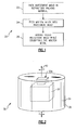
- Figure 1 illustrates an example method of forming a cast component, such as a turbine blade or other type of component.
- Cast structures or components may have a distinct alloy microstructure with regard to grain size and grain size distribution that depends on the rate of heat removal during casting and solidification.
- the grain structure controls the properties and behavior of the component during service.
- One premise of this disclosure is that different cooling rates in different locations of a component during solidification result in different microstructures at those locations that cause a variance in the properties of the component from location to location.
- the method 20 may be employed, as will be described below, to facilitate mitigating such differences in microstructure and thereby provide a smaller and more uniform grain size throughout a component.
- the method 20 may include a packing step 22, a feeding step 24, and an agitating step 26. As represented by the dashed line outlining the packing step 22, this step may be conducted separately in time or space from the feeding step 24 and the agitating step 26. Thus, in some examples, the packing step 22 may not be considered to be part of the method 20.
- the packing step 22 may include packing an investment mold in a heat-insulating packing material.
- the investment mold may be formed in a known manner by casting a ceramic slurry around a wax core to form a refractory shell that serves as the investment mold. It is to be understood that the investment mold is not limited to any particular type and the method 20 disclosed herein may be adapted for use with many different types of investment molds.
- FIG. 2 illustrates an example of a packing 30 that is packed according to the packing step 22.
- an investment mold 32 is packed in a heat-insulating packing material 34 within a vessel 36.
- the illustrated vessel 36 is a cylindrical container but in other examples may have another shape that suitable for the particular process.
- the cylindrical shape of the vessel 36 facilitates handling the packing 30 between the feeding step 24 and the agitating step 26, such as with an automated machine (e.g., a robot).
- the heat-insulating packing material 34 may be a granular ceramic material that is loaded into the vessel 36 along with the investment mold 32. For instance, a base layer of the granular ceramic material may be deposited on the bottom of the vessel 36 and the investment mold 32 may be placed on the base layer. Additional granular ceramic material may be provided around the investment mold 32 such that there is a relatively uniform amount of the granular ceramic material between the walls of the investment mold 32 and the walls of the vessel 36. In this case, a top portion 32a of the investment mold 32 may remain exposed relative to the heat-insulating packing material 34 to allow feeding the molten alloy into the investment mold 32.
- the granular ceramic material may be an oxide, a carbide, a nitride, or combinations thereof. In one example, the granular ceramic may be alumina. In any case, the granular ceramic material thermally insulates the investment mold 32 such that the molten metal, once poured into the investment mold 32, remains molten while the packing 30 is handled, as will be described below.
- the packing 30 may be moved into a casting furnace to conduct the feeding step 24.
- the casting furnace may be a standard type of casting furnace and need not necessarily be specially designed with regard to the agitating step 26. That is, the agitating step 26 may be conducted in a second, separate and distinct machine (e.g., an agitator).
- the molten alloy is fed into the investment mold 32 that is packed in the heat-insulating packing material 34 to provide a filled investment mold.
- the molten metal may be poured from a refractory ladle or the like, as is generally known.
- the packing 30 may then be removed from the casting furnace into an agitator that is separate from the casting furnace to conduct the agitating step 26.
- the packing 30 provides the benefit of insulating the investment mold 32 during movement of the packing 30 between the feeding step 24 and the agitating step 26 to limit or prevent solidification of the molten alloy.
- a standard type of casting furnace may be used and there is no need to specially adapt this machine for agitation or vibration.
- the separate agitator can be a very simple type of machine and the method 20 therefore provides an economical solution to casting components with agitation.
- the agitator agitates the filled investment mold while the molten alloy solidifies.
- the agitator may rotationally agitate the packing 30 about an axis 40.
- the axis 40 may be a central axis of the investment mold 32 or component within the investment mold 32, or other desired axis, such as a vertical axis.
- the agitator may rotate the packing 30 back and forth about the axis 40.
- the agitator may change between rotation directions (i.e., clockwise and counterclockwise) after predetermined periods of rotation and rotate the packing 30 at an angular velocity of 10-500 revolutions per minute in the given direction. In some examples for casting a turbine blade, the angular velocity may be 30-80 revolutions per minute.
- the angular velocity is approximately 50 revolutions per minute.
- the periods of rotation may be approximately 1-10 seconds.
- the agitator may cyclically rotate the packing 30 clockwise for about three seconds and then counterclockwise for about one second. Each cycle includes one rotation clockwise and one rotation counterclockwise.
- the frequency may refer to the angular velocity or number oscillations per unit time, and the amplitude may refer to the angular travel about the axis 40. The frequency and amplitude may be predetermined depending upon the particular design of the component.
- the movement of the packing 30 serves to break up the solids that begin to form during the cooling of the molten alloy.
- the agitation refines the grain structure by fragmenting the solids that form initially from the liquidus state of the molten alloy and thereby provides a smaller and more uniform microstructure throughout the component.
- the heat-insulating packing material 34 in combination with the agitation facilitates reducing the difference in microstructure from location to location that might normally occur from different cooling rates at the different locations.
- the investment mold 32 may be removed from the heat-insulating packing material 34, and the investment mold 32 subsequently removed from the molded component in a known manner. The heat-insulating packing mater 34 may then be reused with another investment mold 32 for subsequent molding cycles.
- the feeding step 24 may be conducted under a first pressure atmosphere (e.g., less than ambient pressure) and the agitating step 26 may be conducted at a higher, second pressure atmosphere.
- a protective gas may be flowed over the exposed top portion 32a of the investment mold 32 to blanket the molten alloy from reacting with the surrounding atmosphere.
- a protective gas such as argon may be used.
- the present invention can be seen to provide a method according to the following clauses.
Landscapes
- Engineering & Computer Science (AREA)
- Mechanical Engineering (AREA)
- Molds, Cores, And Manufacturing Methods Thereof (AREA)
- Dental Prosthetics (AREA)
Abstract
Description
- This disclosure relates to casting metal alloy materials to achieve a more uniform microstructure.
- Investment casting is known and used for fabricating near net shape components of relatively complex geometries from high temperature alloys. Typically, the process includes forming a wax pattern of the component and coating the wax pattern with a ceramic slurry. The slurry is fired to form a refractory shell investment mold and the wax is removed from the interior to form a molding cavity within the shell. A molten alloy is then poured into the cavity to form the component.
- According to a first aspect of the present invention, an example method of forming a cast component includes surrounding at least a portion of an investment mold with a heat-insulating material, feeding a molten alloy into the investment mold that is packed in the heat-insulating packing material to provide a filled investment mold, and agitating the filled investment mold while solidifying the molten alloy.
- Certain preferred embodiments of the present invention will now be described in greater detail by way of example only and with reference to the accompanying drawings in which:
-
Figure 1 illustrates example methods of forming a cast component; and -
Figure 2 illustrates an example packing that includes an investment mold packed within a heat-insulating packing material. -
Figure 1 illustrates an example method of forming a cast component, such as a turbine blade or other type of component. Cast structures or components may have a distinct alloy microstructure with regard to grain size and grain size distribution that depends on the rate of heat removal during casting and solidification. The grain structure controls the properties and behavior of the component during service. One premise of this disclosure is that different cooling rates in different locations of a component during solidification result in different microstructures at those locations that cause a variance in the properties of the component from location to location. Themethod 20 may be employed, as will be described below, to facilitate mitigating such differences in microstructure and thereby provide a smaller and more uniform grain size throughout a component. - In the illustrated example, the
method 20 may include apacking step 22, afeeding step 24, and anagitating step 26. As represented by the dashed line outlining thepacking step 22, this step may be conducted separately in time or space from thefeeding step 24 and theagitating step 26. Thus, in some examples, thepacking step 22 may not be considered to be part of themethod 20. - The
packing step 22 may include packing an investment mold in a heat-insulating packing material. As an example, the investment mold may be formed in a known manner by casting a ceramic slurry around a wax core to form a refractory shell that serves as the investment mold. It is to be understood that the investment mold is not limited to any particular type and themethod 20 disclosed herein may be adapted for use with many different types of investment molds. -
Figure 2 illustrates an example of apacking 30 that is packed according to thepacking step 22. In this case, aninvestment mold 32 is packed in a heat-insulatingpacking material 34 within avessel 36. The illustratedvessel 36 is a cylindrical container but in other examples may have another shape that suitable for the particular process. In this case, the cylindrical shape of thevessel 36 facilitates handling thepacking 30 between thefeeding step 24 and theagitating step 26, such as with an automated machine (e.g., a robot). - The heat-insulating
packing material 34 may be a granular ceramic material that is loaded into thevessel 36 along with theinvestment mold 32. For instance, a base layer of the granular ceramic material may be deposited on the bottom of thevessel 36 and theinvestment mold 32 may be placed on the base layer. Additional granular ceramic material may be provided around theinvestment mold 32 such that there is a relatively uniform amount of the granular ceramic material between the walls of theinvestment mold 32 and the walls of thevessel 36. In this case, atop portion 32a of theinvestment mold 32 may remain exposed relative to the heat-insulatingpacking material 34 to allow feeding the molten alloy into theinvestment mold 32. - The granular ceramic material may be an oxide, a carbide, a nitride, or combinations thereof. In one example, the granular ceramic may be alumina. In any case, the granular ceramic material thermally insulates the
investment mold 32 such that the molten metal, once poured into theinvestment mold 32, remains molten while thepacking 30 is handled, as will be described below. - After packing the
investment mold 32 in the heat-insulatingpacking material 34, thepacking 30 may be moved into a casting furnace to conduct thefeeding step 24. As an example, the casting furnace may be a standard type of casting furnace and need not necessarily be specially designed with regard to theagitating step 26. That is, theagitating step 26 may be conducted in a second, separate and distinct machine (e.g., an agitator). The molten alloy is fed into theinvestment mold 32 that is packed in the heat-insulatingpacking material 34 to provide a filled investment mold. For instance, the molten metal may be poured from a refractory ladle or the like, as is generally known. - The
packing 30 may then be removed from the casting furnace into an agitator that is separate from the casting furnace to conduct theagitating step 26. Thepacking 30 provides the benefit of insulating theinvestment mold 32 during movement of thepacking 30 between thefeeding step 24 and theagitating step 26 to limit or prevent solidification of the molten alloy. Thus, a standard type of casting furnace may be used and there is no need to specially adapt this machine for agitation or vibration. The separate agitator can be a very simple type of machine and themethod 20 therefore provides an economical solution to casting components with agitation. - The agitator agitates the filled investment mold while the molten alloy solidifies. As an example, the agitator may rotationally agitate the
packing 30 about anaxis 40. Theaxis 40 may be a central axis of theinvestment mold 32 or component within theinvestment mold 32, or other desired axis, such as a vertical axis. In this case, the agitator may rotate thepacking 30 back and forth about theaxis 40. As an example, the agitator may change between rotation directions (i.e., clockwise and counterclockwise) after predetermined periods of rotation and rotate thepacking 30 at an angular velocity of 10-500 revolutions per minute in the given direction. In some examples for casting a turbine blade, the angular velocity may be 30-80 revolutions per minute. In a further turbine blade example, the angular velocity is approximately 50 revolutions per minute. The periods of rotation may be approximately 1-10 seconds. For instance, the agitator may cyclically rotate thepacking 30 clockwise for about three seconds and then counterclockwise for about one second. Each cycle includes one rotation clockwise and one rotation counterclockwise. The frequency may refer to the angular velocity or number oscillations per unit time, and the amplitude may refer to the angular travel about theaxis 40. The frequency and amplitude may be predetermined depending upon the particular design of the component. - During agitation, the movement of the
packing 30 serves to break up the solids that begin to form during the cooling of the molten alloy. Thus, the agitation refines the grain structure by fragmenting the solids that form initially from the liquidus state of the molten alloy and thereby provides a smaller and more uniform microstructure throughout the component. Thus, the heat-insulatingpacking material 34 in combination with the agitation facilitates reducing the difference in microstructure from location to location that might normally occur from different cooling rates at the different locations. After solidification, theinvestment mold 32 may be removed from the heat-insulatingpacking material 34, and theinvestment mold 32 subsequently removed from the molded component in a known manner. The heat-insulatingpacking mater 34 may then be reused with anotherinvestment mold 32 for subsequent molding cycles. - In some examples, the
feeding step 24 may be conducted under a first pressure atmosphere (e.g., less than ambient pressure) and theagitating step 26 may be conducted at a higher, second pressure atmosphere. In cases where reaction of the molten alloy with the surrounding atmosphere is a concern, a protective gas may be flowed over the exposedtop portion 32a of theinvestment mold 32 to blanket the molten alloy from reacting with the surrounding atmosphere. As an example, a protective gas such as argon may be used. - Although a combination of features is shown in the illustrated examples, not all of them need to be combined to realize the benefits of various embodiments of this disclosure. In other words, a system designed according to an embodiment of this disclosure will not necessarily include all of the features shown in any one of the Figures or all of the portions schematically shown in the Figures. Moreover, selected features of one example embodiment may be combined with selected features of other example embodiments.
- The preceding description is exemplary rather than limiting in nature. The scope of legal protection given to this disclosure can only be determined by studying the following claims.
- In one preferred embodiment, the present invention can be seen to provide a method according to the following clauses.
- 1. A method of forming a cast component, comprising:
- feeding a molten alloy into an investment mold that is packed in a heat-insulating packing material to provide a filled investment mold; and
- agitating the filled investment mold while solidifying the molten alloy.
- 2. The method as recited in clause 1, wherein the agitating of the filled investment mold includes rotating the filled investment mold back and forth around an axis of the investment mold.
- 3. The method as recited in clause 1 or 2, including cyclically rotating the filled investment mold back and forth between clockwise and counterclockwise directions at an angular velocity of 10-500 revolutions per minute for periods of rotation of 1-10 seconds.
- 4. The method as recited in clause 1, 2 or 3, including feeding the molten alloy under an evacuated, first pressure atmosphere in a casting furnace and agitating the filled investment mold under a higher, second pressure atmosphere in an agitator that is separate and distinct from the casting furnace.
Claims (15)
- A method of forming a cast component, comprising:at least partially surrounding an investment mold in a heat-insulating material;feeding a molten alloy into the investment mold that is at least partially surrounded in the heat-insulating packing material to provide a filled investment mold; andagitating the filled investment mold while solidifying the molten alloy.
- The method as recited in claim 1, wherein the heat-insulating material is a granular ceramic material.
- The method as recited in claim 2, wherein the granular ceramic material is selected from a group consisting of oxides, carbides, nitrides, and combinations thereof.
- The method as recited in claim 2 or 3, wherein the granular ceramic material is alumina.
- The method as recited in any preceding claim, wherein the investment mold is a refractory shell.
- The method as recited in any preceding claim, including packing the investment mold and the heat-insulating material in a vessel such that the investment mold is substantially surrounded by the heat-insulating material between walls of the vessel and the investment mold.
- The method as recited in any preceding claim, wherein the partially surrounding comprises packing the investment mold in heat insulating material.
- The method as recited in any preceding claim, wherein the agitating of the filled investment mold includes rotating the filled investment mold back and forth around an axis of the investment mold, and preferably the axis is vertical.
- The method as recited in claim 8, including cyclically rotating the filled investment mold back and forth between clockwise and counterclockwise directions at an angular velocity of 10-500 revolutions per minute for periods of rotation of 1-10 seconds.
- The method as recited in claim 9, wherein the angular velocity is 30-80 revolutions per minute and preferably the angular velocity is approximately 50 revolutions per minute.
- The method as recited in claim 9 or 10, including cyclically rotating the filled investment mold clockwise for approximately three seconds and then counterclockwise for approximately 1 second.
- The method as recited in any preceding claim, including feeding the molten alloy under an evacuated, first pressure atmosphere in a casting furnace and agitating the filled investment mold under a higher, second pressure atmosphere in an agitator that is separate and distinct from the casting furnace.
- The method as recited in any preceding claim, including feeding of the molten alloy in a first machine and then moving the filled investment mold to a second, different machine to conduct the agitation such that the heat-insulating packing material insulates the investment mold so that substantially no solidification occurs during moving of the filled investment mold between the first machine and the second machine.
- The method as recited in any preceding claim, further comprising flowing a protective gas over at least an exposed portion of the investment mold during the agitating.
- The method as recited in any preceding claim, further comprising reusing the heat-insulating packing material after solidification of the molten metal to pack another investment mold.
Applications Claiming Priority (1)
| Application Number | Priority Date | Filing Date | Title |
|---|---|---|---|
| US12/696,304 US8240355B2 (en) | 2010-01-29 | 2010-01-29 | Forming a cast component with agitation |
Publications (3)
| Publication Number | Publication Date |
|---|---|
| EP2390026A2 true EP2390026A2 (en) | 2011-11-30 |
| EP2390026A3 EP2390026A3 (en) | 2012-10-24 |
| EP2390026B1 EP2390026B1 (en) | 2015-12-30 |
Family
ID=44146545
Family Applications (1)
| Application Number | Title | Priority Date | Filing Date |
|---|---|---|---|
| EP11250099.6A Active EP2390026B1 (en) | 2010-01-29 | 2011-01-28 | Forming a cast component with agitation |
Country Status (2)
| Country | Link |
|---|---|
| US (1) | US8240355B2 (en) |
| EP (1) | EP2390026B1 (en) |
Families Citing this family (2)
| Publication number | Priority date | Publication date | Assignee | Title |
|---|---|---|---|---|
| US10498933B2 (en) * | 2011-11-22 | 2019-12-03 | Cognex Corporation | Camera system with exchangeable illumination assembly |
| US10695826B2 (en) * | 2017-07-17 | 2020-06-30 | Raytheon Technologies Corporation | Apparatus and method for investment casting core manufacture |
Family Cites Families (18)
| Publication number | Priority date | Publication date | Assignee | Title |
|---|---|---|---|---|
| CH299437A (en) * | 1951-07-17 | 1954-06-15 | Boehler & Co Ag Geb | Process for making castings. |
| US2848775A (en) * | 1953-09-17 | 1958-08-26 | Etma S A | Method of controlling the properties of metals and metal alloys by irradiation with vibrations |
| US3204303A (en) * | 1963-06-20 | 1965-09-07 | Thompson Ramo Wooldridge Inc | Precision investment casting |
| US3568752A (en) * | 1968-12-05 | 1971-03-09 | Univ Ohio State | Method for controlling the as-cast grain structure of solidified materials |
| US3981344A (en) * | 1974-08-21 | 1976-09-21 | United Technologies Corporation | Investment casting mold and process |
| US4078951A (en) * | 1976-03-31 | 1978-03-14 | University Patents, Inc. | Method of improving fatigue life of cast nickel based superalloys and composition |
| GB1515933A (en) | 1976-10-05 | 1978-06-28 | Hocking L | Method of casting |
| US4462454A (en) * | 1981-11-12 | 1984-07-31 | Michigan Technological University | Method for reducing macrosegregation in alloys |
| GB8408975D0 (en) * | 1984-04-06 | 1984-05-16 | Wood J V | Titanium alloys |
| US4813470A (en) * | 1987-11-05 | 1989-03-21 | Allied-Signal Inc. | Casting turbine components with integral airfoils |
| US5291654A (en) * | 1993-03-29 | 1994-03-08 | United Technologies Corporation | Method for producing hollow investment castings |
| US5931214A (en) * | 1997-08-07 | 1999-08-03 | Howmet Research Corporation | Mold heating vacuum casting furnace |
| US6932145B2 (en) * | 1998-11-20 | 2005-08-23 | Rolls-Royce Corporation | Method and apparatus for production of a cast component |
| US6766850B2 (en) * | 2001-12-27 | 2004-07-27 | Caterpillar Inc | Pressure casting using a supported shell mold |
| US6986381B2 (en) * | 2003-07-23 | 2006-01-17 | Santoku America, Inc. | Castings of metallic alloys with improved surface quality, structural integrity and mechanical properties fabricated in refractory metals and refractory metal carbides coated graphite molds under vacuum |
| US7201212B2 (en) * | 2003-08-28 | 2007-04-10 | United Technologies Corporation | Investment casting |
| US7712511B2 (en) * | 2005-03-15 | 2010-05-11 | The Japan Steel Works, Ltd. | Casting method and casting apparatus |
| US7306026B2 (en) * | 2005-09-01 | 2007-12-11 | United Technologies Corporation | Cooled turbine airfoils and methods of manufacture |
-
2010
- 2010-01-29 US US12/696,304 patent/US8240355B2/en active Active
-
2011
- 2011-01-28 EP EP11250099.6A patent/EP2390026B1/en active Active
Non-Patent Citations (1)
| Title |
|---|
| None |
Also Published As
| Publication number | Publication date |
|---|---|
| EP2390026B1 (en) | 2015-12-30 |
| EP2390026A3 (en) | 2012-10-24 |
| US20110186258A1 (en) | 2011-08-04 |
| US8240355B2 (en) | 2012-08-14 |
Similar Documents
| Publication | Publication Date | Title |
|---|---|---|
| EP2606994B1 (en) | Induction stirred, ultrasonically modified investment castings and apparatus for producing | |
| RU2635596C2 (en) | Method for manufacturing hollow metal workpiece by casting | |
| RU2146184C1 (en) | Method and apparatus for directional crystallization of melt | |
| EP3027342B1 (en) | Forming a metal component | |
| US20130160967A1 (en) | Casting methods for making articles having a fine equiaxed grain structure | |
| US5335717A (en) | Oxidation resistant superalloy castings | |
| JPH0987030A (en) | Method and apparatus for directional solidification of melts | |
| US8240355B2 (en) | Forming a cast component with agitation | |
| EP3112048B1 (en) | Variable diameter investment casting mold of reticulated metal foams | |
| EP2565615A1 (en) | Container for thermal analysis of cast iron | |
| US20030213575A1 (en) | Melting crucible and method | |
| US20120051898A1 (en) | Wind turbine component having a lightweight structure | |
| EP0826445A2 (en) | Method of making fine grained castings | |
| JP5042384B1 (en) | Casting apparatus and casting method | |
| US6263951B1 (en) | Horizontal rotating directional solidification | |
| JP2666725B2 (en) | Sand mold | |
| JP2004306044A (en) | Precision casting apparatus and precision casting method using the same | |
| EP2830792B1 (en) | Continuous casting process of metal | |
| EP2581149B1 (en) | Method for producing a metal part | |
| US20130032303A1 (en) | Wind turbine component having a lightweight structure | |
| EP0099470A1 (en) | Casting non-ferrous metals | |
| EP3059030B1 (en) | Bondcasting process using investment and sand casting | |
| EP3586993B1 (en) | Production of multi-passage hollow casting | |
| EP1048759A1 (en) | Horizontal directional solidification | |
| KR20170059256A (en) | Electric Furnace |
Legal Events
| Date | Code | Title | Description |
|---|---|---|---|
| AK | Designated contracting states |
Kind code of ref document: A2 Designated state(s): AL AT BE BG CH CY CZ DE DK EE ES FI FR GB GR HR HU IE IS IT LI LT LU LV MC MK MT NL NO PL PT RO RS SE SI SK SM TR |
|
| AX | Request for extension of the european patent |
Extension state: BA ME |
|
| PUAI | Public reference made under article 153(3) epc to a published international application that has entered the european phase |
Free format text: ORIGINAL CODE: 0009012 |
|
| REG | Reference to a national code |
Ref country code: DE Ref legal event code: R079 Ref document number: 602011022219 Country of ref document: DE Free format text: PREVIOUS MAIN CLASS: B22D0027000000 Ipc: B22D0027080000 |
|
| PUAL | Search report despatched |
Free format text: ORIGINAL CODE: 0009013 |
|
| AK | Designated contracting states |
Kind code of ref document: A3 Designated state(s): AL AT BE BG CH CY CZ DE DK EE ES FI FR GB GR HR HU IE IS IT LI LT LU LV MC MK MT NL NO PL PT RO RS SE SI SK SM TR |
|
| AX | Request for extension of the european patent |
Extension state: BA ME |
|
| RIC1 | Information provided on ipc code assigned before grant |
Ipc: B22D 27/08 20060101AFI20120919BHEP |
|
| 17P | Request for examination filed |
Effective date: 20130424 |
|
| GRAP | Despatch of communication of intention to grant a patent |
Free format text: ORIGINAL CODE: EPIDOSNIGR1 |
|
| INTG | Intention to grant announced |
Effective date: 20150825 |
|
| GRAS | Grant fee paid |
Free format text: ORIGINAL CODE: EPIDOSNIGR3 |
|
| GRAA | (expected) grant |
Free format text: ORIGINAL CODE: 0009210 |
|
| AK | Designated contracting states |
Kind code of ref document: B1 Designated state(s): AL AT BE BG CH CY CZ DE DK EE ES FI FR GB GR HR HU IE IS IT LI LT LU LV MC MK MT NL NO PL PT RO RS SE SI SK SM TR |
|
| REG | Reference to a national code |
Ref country code: GB Ref legal event code: FG4D |
|
| REG | Reference to a national code |
Ref country code: CH Ref legal event code: EP |
|
| REG | Reference to a national code |
Ref country code: AT Ref legal event code: REF Ref document number: 767224 Country of ref document: AT Kind code of ref document: T Effective date: 20160115 |
|
| REG | Reference to a national code |
Ref country code: IE Ref legal event code: FG4D |
|
| REG | Reference to a national code |
Ref country code: DE Ref legal event code: R096 Ref document number: 602011022219 Country of ref document: DE |
|
| REG | Reference to a national code |
Ref country code: LT Ref legal event code: MG4D |
|
| PG25 | Lapsed in a contracting state [announced via postgrant information from national office to epo] |
Ref country code: NO Free format text: LAPSE BECAUSE OF FAILURE TO SUBMIT A TRANSLATION OF THE DESCRIPTION OR TO PAY THE FEE WITHIN THE PRESCRIBED TIME-LIMIT Effective date: 20160330 Ref country code: HR Free format text: LAPSE BECAUSE OF FAILURE TO SUBMIT A TRANSLATION OF THE DESCRIPTION OR TO PAY THE FEE WITHIN THE PRESCRIBED TIME-LIMIT Effective date: 20151230 Ref country code: LT Free format text: LAPSE BECAUSE OF FAILURE TO SUBMIT A TRANSLATION OF THE DESCRIPTION OR TO PAY THE FEE WITHIN THE PRESCRIBED TIME-LIMIT Effective date: 20151230 |
|
| REG | Reference to a national code |
Ref country code: NL Ref legal event code: MP Effective date: 20151230 |
|
| REG | Reference to a national code |
Ref country code: AT Ref legal event code: MK05 Ref document number: 767224 Country of ref document: AT Kind code of ref document: T Effective date: 20151230 |
|
| PG25 | Lapsed in a contracting state [announced via postgrant information from national office to epo] |
Ref country code: BE Free format text: LAPSE BECAUSE OF NON-PAYMENT OF DUE FEES Effective date: 20160131 Ref country code: GR Free format text: LAPSE BECAUSE OF FAILURE TO SUBMIT A TRANSLATION OF THE DESCRIPTION OR TO PAY THE FEE WITHIN THE PRESCRIBED TIME-LIMIT Effective date: 20160331 Ref country code: LV Free format text: LAPSE BECAUSE OF FAILURE TO SUBMIT A TRANSLATION OF THE DESCRIPTION OR TO PAY THE FEE WITHIN THE PRESCRIBED TIME-LIMIT Effective date: 20151230 Ref country code: FI Free format text: LAPSE BECAUSE OF FAILURE TO SUBMIT A TRANSLATION OF THE DESCRIPTION OR TO PAY THE FEE WITHIN THE PRESCRIBED TIME-LIMIT Effective date: 20151230 Ref country code: SE Free format text: LAPSE BECAUSE OF FAILURE TO SUBMIT A TRANSLATION OF THE DESCRIPTION OR TO PAY THE FEE WITHIN THE PRESCRIBED TIME-LIMIT Effective date: 20151230 Ref country code: RS Free format text: LAPSE BECAUSE OF FAILURE TO SUBMIT A TRANSLATION OF THE DESCRIPTION OR TO PAY THE FEE WITHIN THE PRESCRIBED TIME-LIMIT Effective date: 20151230 |
|
| PG25 | Lapsed in a contracting state [announced via postgrant information from national office to epo] |
Ref country code: NL Free format text: LAPSE BECAUSE OF FAILURE TO SUBMIT A TRANSLATION OF THE DESCRIPTION OR TO PAY THE FEE WITHIN THE PRESCRIBED TIME-LIMIT Effective date: 20151230 |
|
| PG25 | Lapsed in a contracting state [announced via postgrant information from national office to epo] |
Ref country code: CZ Free format text: LAPSE BECAUSE OF FAILURE TO SUBMIT A TRANSLATION OF THE DESCRIPTION OR TO PAY THE FEE WITHIN THE PRESCRIBED TIME-LIMIT Effective date: 20151230 Ref country code: IT Free format text: LAPSE BECAUSE OF FAILURE TO SUBMIT A TRANSLATION OF THE DESCRIPTION OR TO PAY THE FEE WITHIN THE PRESCRIBED TIME-LIMIT Effective date: 20151230 Ref country code: ES Free format text: LAPSE BECAUSE OF FAILURE TO SUBMIT A TRANSLATION OF THE DESCRIPTION OR TO PAY THE FEE WITHIN THE PRESCRIBED TIME-LIMIT Effective date: 20151230 |
|
| PG25 | Lapsed in a contracting state [announced via postgrant information from national office to epo] |
Ref country code: PL Free format text: LAPSE BECAUSE OF FAILURE TO SUBMIT A TRANSLATION OF THE DESCRIPTION OR TO PAY THE FEE WITHIN THE PRESCRIBED TIME-LIMIT Effective date: 20151230 Ref country code: PT Free format text: LAPSE BECAUSE OF FAILURE TO SUBMIT A TRANSLATION OF THE DESCRIPTION OR TO PAY THE FEE WITHIN THE PRESCRIBED TIME-LIMIT Effective date: 20160502 Ref country code: AT Free format text: LAPSE BECAUSE OF FAILURE TO SUBMIT A TRANSLATION OF THE DESCRIPTION OR TO PAY THE FEE WITHIN THE PRESCRIBED TIME-LIMIT Effective date: 20151230 Ref country code: SK Free format text: LAPSE BECAUSE OF FAILURE TO SUBMIT A TRANSLATION OF THE DESCRIPTION OR TO PAY THE FEE WITHIN THE PRESCRIBED TIME-LIMIT Effective date: 20151230 Ref country code: EE Free format text: LAPSE BECAUSE OF FAILURE TO SUBMIT A TRANSLATION OF THE DESCRIPTION OR TO PAY THE FEE WITHIN THE PRESCRIBED TIME-LIMIT Effective date: 20151230 Ref country code: RO Free format text: LAPSE BECAUSE OF FAILURE TO SUBMIT A TRANSLATION OF THE DESCRIPTION OR TO PAY THE FEE WITHIN THE PRESCRIBED TIME-LIMIT Effective date: 20151230 Ref country code: IS Free format text: LAPSE BECAUSE OF FAILURE TO SUBMIT A TRANSLATION OF THE DESCRIPTION OR TO PAY THE FEE WITHIN THE PRESCRIBED TIME-LIMIT Effective date: 20160430 Ref country code: LU Free format text: LAPSE BECAUSE OF FAILURE TO SUBMIT A TRANSLATION OF THE DESCRIPTION OR TO PAY THE FEE WITHIN THE PRESCRIBED TIME-LIMIT Effective date: 20160128 Ref country code: SM Free format text: LAPSE BECAUSE OF FAILURE TO SUBMIT A TRANSLATION OF THE DESCRIPTION OR TO PAY THE FEE WITHIN THE PRESCRIBED TIME-LIMIT Effective date: 20151230 |
|
| REG | Reference to a national code |
Ref country code: CH Ref legal event code: PL |
|
| PG25 | Lapsed in a contracting state [announced via postgrant information from national office to epo] |
Ref country code: MC Free format text: LAPSE BECAUSE OF FAILURE TO SUBMIT A TRANSLATION OF THE DESCRIPTION OR TO PAY THE FEE WITHIN THE PRESCRIBED TIME-LIMIT Effective date: 20151230 |
|
| REG | Reference to a national code |
Ref country code: DE Ref legal event code: R097 Ref document number: 602011022219 Country of ref document: DE |
|
| RAP2 | Party data changed (patent owner data changed or rights of a patent transferred) |
Owner name: UNITED TECHNOLOGIES CORPORATION |
|
| PG25 | Lapsed in a contracting state [announced via postgrant information from national office to epo] |
Ref country code: LI Free format text: LAPSE BECAUSE OF NON-PAYMENT OF DUE FEES Effective date: 20160131 Ref country code: DK Free format text: LAPSE BECAUSE OF FAILURE TO SUBMIT A TRANSLATION OF THE DESCRIPTION OR TO PAY THE FEE WITHIN THE PRESCRIBED TIME-LIMIT Effective date: 20151230 Ref country code: CH Free format text: LAPSE BECAUSE OF NON-PAYMENT OF DUE FEES Effective date: 20160131 |
|
| REG | Reference to a national code |
Ref country code: IE Ref legal event code: MM4A |
|
| PLBE | No opposition filed within time limit |
Free format text: ORIGINAL CODE: 0009261 |
|
| STAA | Information on the status of an ep patent application or granted ep patent |
Free format text: STATUS: NO OPPOSITION FILED WITHIN TIME LIMIT |
|
| 26N | No opposition filed |
Effective date: 20161003 |
|
| PG25 | Lapsed in a contracting state [announced via postgrant information from national office to epo] |
Ref country code: BE Free format text: LAPSE BECAUSE OF FAILURE TO SUBMIT A TRANSLATION OF THE DESCRIPTION OR TO PAY THE FEE WITHIN THE PRESCRIBED TIME-LIMIT Effective date: 20151230 |
|
| REG | Reference to a national code |
Ref country code: FR Ref legal event code: ST Effective date: 20161125 |
|
| PG25 | Lapsed in a contracting state [announced via postgrant information from national office to epo] |
Ref country code: FR Free format text: LAPSE BECAUSE OF NON-PAYMENT OF DUE FEES Effective date: 20160229 Ref country code: IE Free format text: LAPSE BECAUSE OF NON-PAYMENT OF DUE FEES Effective date: 20160128 |
|
| PG25 | Lapsed in a contracting state [announced via postgrant information from national office to epo] |
Ref country code: SI Free format text: LAPSE BECAUSE OF FAILURE TO SUBMIT A TRANSLATION OF THE DESCRIPTION OR TO PAY THE FEE WITHIN THE PRESCRIBED TIME-LIMIT Effective date: 20151230 |
|
| REG | Reference to a national code |
Ref country code: DE Ref legal event code: R082 Ref document number: 602011022219 Country of ref document: DE Representative=s name: SCHMITT-NILSON SCHRAUD WAIBEL WOHLFROM PATENTA, DE |
|
| REG | Reference to a national code |
Ref country code: DE Ref legal event code: R082 Ref document number: 602011022219 Country of ref document: DE Representative=s name: SCHMITT-NILSON SCHRAUD WAIBEL WOHLFROM PATENTA, DE Ref country code: DE Ref legal event code: R081 Ref document number: 602011022219 Country of ref document: DE Owner name: UNITED TECHNOLOGIES CORP. (N.D.GES.D. STAATES , US Free format text: FORMER OWNER: UNITED TECHNOLOGIES CORPORATION, HARTFORD, CONN., US |
|
| PG25 | Lapsed in a contracting state [announced via postgrant information from national office to epo] |
Ref country code: MT Free format text: LAPSE BECAUSE OF FAILURE TO SUBMIT A TRANSLATION OF THE DESCRIPTION OR TO PAY THE FEE WITHIN THE PRESCRIBED TIME-LIMIT Effective date: 20151230 |
|
| PG25 | Lapsed in a contracting state [announced via postgrant information from national office to epo] |
Ref country code: CY Free format text: LAPSE BECAUSE OF FAILURE TO SUBMIT A TRANSLATION OF THE DESCRIPTION OR TO PAY THE FEE WITHIN THE PRESCRIBED TIME-LIMIT Effective date: 20151230 Ref country code: HU Free format text: LAPSE BECAUSE OF FAILURE TO SUBMIT A TRANSLATION OF THE DESCRIPTION OR TO PAY THE FEE WITHIN THE PRESCRIBED TIME-LIMIT; INVALID AB INITIO Effective date: 20110128 |
|
| PG25 | Lapsed in a contracting state [announced via postgrant information from national office to epo] |
Ref country code: TR Free format text: LAPSE BECAUSE OF FAILURE TO SUBMIT A TRANSLATION OF THE DESCRIPTION OR TO PAY THE FEE WITHIN THE PRESCRIBED TIME-LIMIT Effective date: 20151230 Ref country code: MK Free format text: LAPSE BECAUSE OF FAILURE TO SUBMIT A TRANSLATION OF THE DESCRIPTION OR TO PAY THE FEE WITHIN THE PRESCRIBED TIME-LIMIT Effective date: 20151230 Ref country code: MT Free format text: LAPSE BECAUSE OF FAILURE TO SUBMIT A TRANSLATION OF THE DESCRIPTION OR TO PAY THE FEE WITHIN THE PRESCRIBED TIME-LIMIT Effective date: 20160131 |
|
| PG25 | Lapsed in a contracting state [announced via postgrant information from national office to epo] |
Ref country code: BG Free format text: LAPSE BECAUSE OF FAILURE TO SUBMIT A TRANSLATION OF THE DESCRIPTION OR TO PAY THE FEE WITHIN THE PRESCRIBED TIME-LIMIT Effective date: 20151230 |
|
| PG25 | Lapsed in a contracting state [announced via postgrant information from national office to epo] |
Ref country code: AL Free format text: LAPSE BECAUSE OF FAILURE TO SUBMIT A TRANSLATION OF THE DESCRIPTION OR TO PAY THE FEE WITHIN THE PRESCRIBED TIME-LIMIT Effective date: 20151230 |
|
| REG | Reference to a national code |
Ref country code: DE Ref legal event code: R081 Ref document number: 602011022219 Country of ref document: DE Owner name: RAYTHEON TECHNOLOGIES CORPORATION (N.D.GES.D.S, US Free format text: FORMER OWNER: UNITED TECHNOLOGIES CORP. (N.D.GES.D. STAATES DELAWARE), FARMINGTON, CONN., US Ref country code: DE Ref legal event code: R081 Ref document number: 602011022219 Country of ref document: DE Owner name: RTX CORPORATION (N.D.GES.D. STAATES DELAWARE),, US Free format text: FORMER OWNER: UNITED TECHNOLOGIES CORP. (N.D.GES.D. STAATES DELAWARE), FARMINGTON, CONN., US |
|
| P01 | Opt-out of the competence of the unified patent court (upc) registered |
Effective date: 20230520 |
|
| REG | Reference to a national code |
Ref country code: DE Ref legal event code: R081 Ref document number: 602011022219 Country of ref document: DE Owner name: RTX CORPORATION (N.D.GES.D. STAATES DELAWARE),, US Free format text: FORMER OWNER: RAYTHEON TECHNOLOGIES CORPORATION (N.D.GES.D.STAATES DELAWARE), ARLINGTON, VA, US |
|
| PGFP | Annual fee paid to national office [announced via postgrant information from national office to epo] |
Ref country code: GB Payment date: 20251220 Year of fee payment: 16 |
|
| PGFP | Annual fee paid to national office [announced via postgrant information from national office to epo] |
Ref country code: DE Payment date: 20251217 Year of fee payment: 16 |