EP2389994A1 - Air cleaner assembly - Google Patents
Air cleaner assembly Download PDFInfo
- Publication number
- EP2389994A1 EP2389994A1 EP11177393A EP11177393A EP2389994A1 EP 2389994 A1 EP2389994 A1 EP 2389994A1 EP 11177393 A EP11177393 A EP 11177393A EP 11177393 A EP11177393 A EP 11177393A EP 2389994 A1 EP2389994 A1 EP 2389994A1
- Authority
- EP
- European Patent Office
- Prior art keywords
- aperture
- arrangement
- scavenge
- splitter
- housing bottom
- Prior art date
- Legal status (The legal status is an assumption and is not a legal conclusion. Google has not performed a legal analysis and makes no representation as to the accuracy of the status listed.)
- Granted
Links
- 238000004891 communication Methods 0.000 claims description 4
- 238000000429 assembly Methods 0.000 abstract description 21
- 230000000712 assembly Effects 0.000 abstract description 21
- 230000014759 maintenance of location Effects 0.000 abstract description 6
- 238000000034 method Methods 0.000 abstract description 6
- 230000004888 barrier function Effects 0.000 description 62
- 239000002516 radical scavenger Substances 0.000 description 31
- 239000000428 dust Substances 0.000 description 23
- 238000004140 cleaning Methods 0.000 description 9
- 230000006835 compression Effects 0.000 description 9
- 238000007906 compression Methods 0.000 description 9
- 238000001914 filtration Methods 0.000 description 8
- 238000010276 construction Methods 0.000 description 5
- 238000012163 sequencing technique Methods 0.000 description 5
- 230000008901 benefit Effects 0.000 description 4
- 230000007246 mechanism Effects 0.000 description 3
- 230000002000 scavenging effect Effects 0.000 description 3
- 238000007789 sealing Methods 0.000 description 3
- 230000007704 transition Effects 0.000 description 3
- 230000001154 acute effect Effects 0.000 description 2
- 238000013459 approach Methods 0.000 description 2
- 238000002485 combustion reaction Methods 0.000 description 2
- 239000000356 contaminant Substances 0.000 description 2
- 238000011109 contamination Methods 0.000 description 2
- 238000009434 installation Methods 0.000 description 2
- 102100039250 Essential MCU regulator, mitochondrial Human genes 0.000 description 1
- 101000813097 Homo sapiens Essential MCU regulator, mitochondrial Proteins 0.000 description 1
- 239000011324 bead Substances 0.000 description 1
- 238000013461 design Methods 0.000 description 1
- 239000006185 dispersion Substances 0.000 description 1
- 238000011156 evaluation Methods 0.000 description 1
- 239000000463 material Substances 0.000 description 1
- 238000005065 mining Methods 0.000 description 1
- 238000012986 modification Methods 0.000 description 1
- 230000004048 modification Effects 0.000 description 1
- 239000011236 particulate material Substances 0.000 description 1
- 230000000737 periodic effect Effects 0.000 description 1
- 229920003023 plastic Polymers 0.000 description 1
- 238000000926 separation method Methods 0.000 description 1
- 238000012360 testing method Methods 0.000 description 1
- 125000000391 vinyl group Chemical group [H]C([*])=C([H])[H] 0.000 description 1
- 229920002554 vinyl polymer Polymers 0.000 description 1
Images


Classifications
-
- B—PERFORMING OPERATIONS; TRANSPORTING
- B01—PHYSICAL OR CHEMICAL PROCESSES OR APPARATUS IN GENERAL
- B01D—SEPARATION
- B01D46/00—Filters or filtering processes specially modified for separating dispersed particles from gases or vapours
- B01D46/24—Particle separators, e.g. dust precipitators, using rigid hollow filter bodies
- B01D46/2403—Particle separators, e.g. dust precipitators, using rigid hollow filter bodies characterised by the physical shape or structure of the filtering element
- B01D46/2411—Filter cartridges
- B01D46/2414—End caps including additional functions or special forms
-
- B—PERFORMING OPERATIONS; TRANSPORTING
- B01—PHYSICAL OR CHEMICAL PROCESSES OR APPARATUS IN GENERAL
- B01D—SEPARATION
- B01D46/00—Filters or filtering processes specially modified for separating dispersed particles from gases or vapours
- B01D46/0002—Casings; Housings; Frame constructions
- B01D46/0005—Mounting of filtering elements within casings, housings or frames
-
- B—PERFORMING OPERATIONS; TRANSPORTING
- B01—PHYSICAL OR CHEMICAL PROCESSES OR APPARATUS IN GENERAL
- B01D—SEPARATION
- B01D46/00—Filters or filtering processes specially modified for separating dispersed particles from gases or vapours
- B01D46/10—Particle separators, e.g. dust precipitators, using filter plates, sheets or pads having plane surfaces
- B01D46/12—Particle separators, e.g. dust precipitators, using filter plates, sheets or pads having plane surfaces in multiple arrangements
- B01D46/121—V-type arrangements
-
- B—PERFORMING OPERATIONS; TRANSPORTING
- B01—PHYSICAL OR CHEMICAL PROCESSES OR APPARATUS IN GENERAL
- B01D—SEPARATION
- B01D46/00—Filters or filtering processes specially modified for separating dispersed particles from gases or vapours
- B01D46/42—Auxiliary equipment or operation thereof
- B01D46/4227—Manipulating filters or filter elements, e.g. handles or extracting tools
-
- B—PERFORMING OPERATIONS; TRANSPORTING
- B01—PHYSICAL OR CHEMICAL PROCESSES OR APPARATUS IN GENERAL
- B01D—SEPARATION
- B01D46/00—Filters or filtering processes specially modified for separating dispersed particles from gases or vapours
- B01D46/42—Auxiliary equipment or operation thereof
- B01D46/48—Removing dust other than cleaning filters, e.g. by using collecting trays
-
- B—PERFORMING OPERATIONS; TRANSPORTING
- B01—PHYSICAL OR CHEMICAL PROCESSES OR APPARATUS IN GENERAL
- B01D—SEPARATION
- B01D46/00—Filters or filtering processes specially modified for separating dispersed particles from gases or vapours
- B01D46/52—Particle separators, e.g. dust precipitators, using filters embodying folded corrugated or wound sheet material
-
- B—PERFORMING OPERATIONS; TRANSPORTING
- B01—PHYSICAL OR CHEMICAL PROCESSES OR APPARATUS IN GENERAL
- B01D—SEPARATION
- B01D46/00—Filters or filtering processes specially modified for separating dispersed particles from gases or vapours
- B01D46/66—Regeneration of the filtering material or filter elements inside the filter
- B01D46/70—Regeneration of the filtering material or filter elements inside the filter by acting counter-currently on the filtering surface, e.g. by flushing on the non-cake side of the filter
- B01D46/71—Regeneration of the filtering material or filter elements inside the filter by acting counter-currently on the filtering surface, e.g. by flushing on the non-cake side of the filter with pressurised gas, e.g. pulsed air
-
- B—PERFORMING OPERATIONS; TRANSPORTING
- B01—PHYSICAL OR CHEMICAL PROCESSES OR APPARATUS IN GENERAL
- B01D—SEPARATION
- B01D50/00—Combinations of methods or devices for separating particles from gases or vapours
- B01D50/20—Combinations of devices covered by groups B01D45/00 and B01D46/00
-
- F—MECHANICAL ENGINEERING; LIGHTING; HEATING; WEAPONS; BLASTING
- F02—COMBUSTION ENGINES; HOT-GAS OR COMBUSTION-PRODUCT ENGINE PLANTS
- F02M—SUPPLYING COMBUSTION ENGINES IN GENERAL WITH COMBUSTIBLE MIXTURES OR CONSTITUENTS THEREOF
- F02M35/00—Combustion-air cleaners, air intakes, intake silencers, or induction systems specially adapted for, or arranged on, internal-combustion engines
- F02M35/02—Air cleaners
- F02M35/08—Air cleaners with means for removing dust, particles or liquids from cleaners; with means for indicating clogging; with by-pass means; Regeneration of cleaners
-
- B—PERFORMING OPERATIONS; TRANSPORTING
- B01—PHYSICAL OR CHEMICAL PROCESSES OR APPARATUS IN GENERAL
- B01D—SEPARATION
- B01D2265/00—Casings, housings or mounting for filters specially adapted for separating dispersed particles from gases or vapours
- B01D2265/02—Non-permanent measures for connecting different parts of the filter
- B01D2265/024—Mounting aids
- B01D2265/025—Mounting aids making use of ramps or cams
-
- B—PERFORMING OPERATIONS; TRANSPORTING
- B01—PHYSICAL OR CHEMICAL PROCESSES OR APPARATUS IN GENERAL
- B01D—SEPARATION
- B01D2271/00—Sealings for filters specially adapted for separating dispersed particles from gases or vapours
- B01D2271/02—Gaskets, sealings
- B01D2271/022—Axial sealings
Definitions
- the present disclosure relates to air cleaners. It particularly concerns features of air cleaner arrangements configured for pulse jet cleaning operation. Specific advantageous features, overall assemblies and methods are described.
- Typical air cleaners utilize a filter having filter media therein, through which the intake air is directed. Particulates are deposited on or in the filter media.
- precleaners for example cyclonic precleaners
- cyclonic precleaners are used before the air is directed into the barrier media.
- An example of such an arrangement is described in U.S. 5,575,826 incorporated herein by reference.
- the filter media is contained within a serviceable filter cartridge.
- serviceable in this context, it is meant that the filter cartridge is of a design that is to be removed from, and be replaced in, the air cleaner, in time.
- pulse air flow is selectively intermittently directed through selected portions of a filter cartridge, to eject collected dust from the filter cartridge.
- the ejected dust falls to a bottom of the air cleaner, to be scavenged therefrom by a scavenge system.
- pulse jet air cleaner systems and components and assemblies for use in pulse jet air cleaner systems are shown.
- the systems include features that provide for efficient pulse jet cleaning of cartridges that have fairly narrow long v-pack assemblies, for example.
- preferred scavenger arrangements or preferred features of scavenger arrangements are shown, for efficient scavenging of pulse jet air cleaners.
- a variety of specific, advantageous features for use in such assemblies are provided, as well as methods of use.
- the reference numeral 1, Fig. 1 generally indicates an air cleaner assembly including selected features according to the present disclosure.
- the air cleaner assembly 1 comprises a precleaner stage 5 and a barrier filter stage 6.
- assembly 1 is shown with a side panel facing the viewer removed, so that selected internal structure can be viewed.
- Fig. 1 is schematic.
- the precleaner stage 5 is positioned above the barrier stage 6, although alternatives are possible in alternate assemblies using the selected principles according to the present disclosure.
- the precleaner stage 5 would typically comprise a frame or housing including a plurality of cyclonic separators such as, for example, described in U.S. Patents 4,008,059 ; 4,050,913 ; 4,289,611 ; 3,448,563 ; 3,713,280 ; 4,985,058 ; and, 4,976,748 , the complete disclosures of these seven references being incorporated herein by reference.
- Such separators will generally cause separation of some dust or other particulate material under centrifugal force.
- the dust is then removed from precleaner stage 5, by upper or precleaner scavenger portion 11 a of scavenger system 11. Partially cleaned air from the precleaner stage 5 is then directed into interior 6a of barrier filter stage 6.
- the precleaner 5 is removable from barrier filter stage 6.
- the barrier filter stage 6 can be viewed as comprising a housing 6b having: a top 6c, a bottom 6d; a first air flow outlet end 6e; and opposite, second, end 6f.
- barrier filter stage 6 can be viewed as a sub housing or a barrier filter housing.
- serviceable filter cartridge 15 is operably positioned within interior 6a of barrier filter stage 6.
- the typical filter cartridge 15 has a v-pack shape described in greater detail below. Examples of v-packs but with different specific features are generally shown and described in U.S. Patents 6,676,721 and Des. 455,826, incorporated herein by reference.
- the particular filter cartridge 15 has certain unique v-pack filter dimensions and configurations discussed in greater detail below.
- Filter cartridge 15 is generally configured for "out-to-in" flow, during filtering. That means that the air flow would generally pass through filter media portions of the cartridge 15, in a direction from exterior 15x of the cartridge 15, to an interior 15i, Fig. 9 , of the cartridge 15, during filtering.
- the assembly 1 includes a pulse jet assembly or arrangement 18.
- the pulse jet assembly or arrangement 18 is configured to direct selected jet pulses of air through the filter cartridge 15, in a direction generally opposite to normal filtering flow, i.e., directed in-to-out with respect to direction of flow through the media.
- Such jet pulses can be directed to knock affected dust or other particulates off of the exterior 15x of the filter cartridge 15, and into bottom region 20 of barrier filter stage 6. From here the dust or other particulates is removed by a barrier filter stage scavenge arrangement, or lower scavenger arrangement 22 of scavenger system 11.
- a blower arrangement for operation of the upper scavenge portion 11a and lower scavenge arrangement 22 is indicated generally at 25, with the scavenger outlet or exhaust shown at arrow 26.
- a blower takeoff from the lower scavenge arrangement 22 is shown at 25a, at a location closer to end 6e than end 6f.
- air which is filtered by passage through filter cartridge 15 is generally directed into clean air plenum 30.
- the clean air passes from plenum 30 outwardly from air cleaner 1, through outlet 31. From there, it can be directed to a turbo intake, engine intake, etc., as needed and appropriate for the system involved.
- Fig. 1 is configured to receive and utilize a single v-pack filter cartridge 15.
- Principles according to the present disclosure could be applied in alternate arrangements, which include more than one v-filter filter cartridge.
- FIG. 3 an opposite end view to the end view of Fig. 2 is depicted.
- the air cleaner assembly 1 is depicted with the precleaner stage 5 removed.
- blower equipment 25, Fig. 1 , below stage 6 is not shown.
- the end view depicts the pulse jet arrangement 18 as comprising an accumulator 35 with a set of valve arrangements 36 thereon.
- the accumulator 35 comprises a compressor vessel for receiving compressed air from a compressor, for use in the pulse jet cleaning.
- the valve arrangements 36 provide for controlled pulse jets from the accumulator 35 through a nozzle and splitter arrangement described below, to clean the v-pack arrangement.
- valve arrangement 36 comprises four valves 37, although alternate arrangements and an alternate number of valves could be used.
- the four valves 37 are arranged in a vertical stack as shown.
- FIG. 4 a cross-section taken along 4-4, Fig. 3 .
- a compressed air flow inlet conduit 40 is depicted, for entering gas flow under pressure into accumulator 35.
- the valves 37 control direction of pulse jets of air from accumulator 35 through nozzles 43 and splitters 44.
- nozzles 43 and four splitters 44 are four nozzles 43 and four splitters 44, one each associated with each valve 37.
- barrier filter stage 6 is viewable with serviceable filter cartridge 15 positioned therein.
- the cross-section of Fig. 4 is taken through the center of the filter cartridge 15. It can be seen that the interior 15i of filter cartridge 15 is divided, in this instance vertically, into a stack of multiple sections or stages. The number of sections or stages is a matter of choice depending on the particular air cleaner, system and cartridge configuration involved. Typically there will be at least two sections or stages, often at least three and usually not more than five, although alternatives are possible.
- the particular cartridge 15 depicted comprises a stack of four sections stages 15a, 15b, 15c and 15d, each separated from the next adjacent one(s), by one of internal barriers 48. From Fig. 4 , it can be seen that each splitter 44 is positioned to direct air into one each of the chambers 15a-15d.
- the cartridge 15 is positioned so that the sections or stages 15a - 15d are stacked vertically on one another. This will be typical for an assembly according to the present disclosure.
- cartridge 15 is inserted or removed from interior 6a, by passage through upper end or top 6c of barrier filter stage 6, when the precleaner assembly 5 is removed or opened.
- dimension AA is depicted. Dimension AA may vary, from system to system. For the particular example shown, dimension AA is 1.2 inches (30.5 mm).
- the serviceable cartridge 15 is depicted in detail, in Figs. 5-9 .
- a top perspective view of the serviceable cartridge 15 is provided.
- the cartridge 15 comprises v-pack panel arrangement 50, a closed narrow end piece or cover 51, and an open air outlet end piece 52.
- the closed end piece 51 is positioned at a narrow end 51a of the v-pack panel arrangement 50 and the open end piece 52 is positioned at a wide end 52a of the v-pack panel arrangement 50.
- the cartridge 15 also includes top and bottom covers or frame pieces 58, 59 discussed below.
- the covers or frame pieces 58, 59 extend between the closed end piece 51 and the open end piece 52.
- v-pack panel arrangement 50 comprises first and second panels 55, 56.
- Each panel 55, 56 typically comprises a panel of barrier media, for example pleated media.
- barrier media for example pleated media.
- the media is pleated, it is positioned within cartridge 15 such that a longitudinal extension of the pleats is directed between top and bottom frame pieces 58, 59.
- the panels 55, 56 are positioned within cartridge 15 to define an interior volume (corresponding to volume 15i); and to extend at an interior angle CC relative to one another.
- Angle CC is typically at least 4° and not greater than 10°, usually 5-7°, inclusive, typically 5.2 - 5.9°, inclusive. (Herein, the term “inclusive" when used with respect to a range, is meant to indicate that the recited end points are included.)
- top frame piece 58 and the bottom frame piece 59 are positioned with the panels 55, 56 therebetween.
- cartridge 15 is depicted in side elevational view.
- dividers 48 positioned in interior 15i discussed above in connection with Fig. 4 are shown.
- the dividers 48 would not typically be viewable in a side elevational view, since panel 55 would block the view.
- Typical arrangements will have at least one divider, often at least two dividers, usually not more than four. The example shown has three.
- cartridge 15 is fit with a top frame piece 58 and bottom piece 59 in extension between end pieces 51, 52 to enclose the cartridges 55, 56.
- air filter media in panels 55, 56 would be provided in a pleated form, in a frame.
- Two framed sections of pleated media would be used to form the side panels 55, 56.
- These two framed pieces would be fitted in a frame defined by top frame piece 58, bottom frame piece 59, closed end 51 and open end piece 52, to form cartridge 15.
- the media could be potted directly to portions of the frame, for example, frame pieces 58 and 59.
- Fig. 6 is an end view of cartridge 15, the view being generally taken toward open end piece 52.
- Fig. 6 one can view through opening or air flow aperture 60 in end piece 52 providing air flow communication with interior 15i of cartridge 15.
- Dividers 48 are now viewable.
- Aperture 60 is a tall, narrow, opening.
- the aspect ratio (width HH to height FF) of the opening is at least 0.06, typically at least 0.07 and usually within the range of 0.07 to 0.14 and typically not more than 0.17.
- the divider(s) 48 are evenly spaced GG along the height dimension, although alternatives are possible.
- Fig. 8 is a cross-sectional view taken along line 8-8, Fig. 5 .
- the top frame piece 58, bottom frame piece 59, panels 55, 56 and dividers 48 are readily viewable. Also viewable is pleated media 55a, 56a in each of the panels 55, 56.
- a top perspective view of cartridge 15 is presented. Attention is directed to handle arrangement 61.
- Handle arrangement 61 is provided on top piece 58, to facilitate lifting of the cartridge 15 into and out of the assembly 1.
- the handle arrangement 61 can have a variety of constructions, and is typically made collapsible, so it can be lowered when not in use.
- the particular handle arrangement 61 depicted comprises an extension of wire 61 a, mounted on the cartridge 15. The wire handle 61 a can be collapsed, when not in use.
- a handle arrangement 61 which forms an open loop 61 b, through which a handler's fingers or portion of a hand can extend, to lift and manipulate the cartridge 15, is generally referred to herein as a "loop handle member" or “loop handle arrangement.”
- Handle arrangement 61 does comprise a loop handle arrangement.
- An alternate "loop handle arrangement" is described below, in connection with other figures.
- the particular loop handle arrangement 61 b depicted in Fig. 9 is a flexible wire loop handle arrangement 61c.
- the open loop 61 b will be configured so that even a person wearing heavy arctic gloves can project fingers through the loop, to manipulate the cartridge 15.
- the wire be a vinyl or plastic coated multi-strand cable, to be easier and more convenient for manipulation.
- bottom frame piece 59 includes a similar wire handle 62.
- the cartridge 15, can, if desired, be manufactured with appropriate symmetry so it can be installed with either piece 58 or piece 59 positioned above the remainder of the cartridge 15, during assembly. Alternate approaches are possible.
- the cartridge 15 could be specifically manufactured without such symmetry, so that it can only be properly inserted into the filter stage or housing 6, in one vertical orientation. When this is done, typically a handle would not be provided in the bottom cover piece 59.
- End piece 52 includes a housing seal or gasket 63 thereon, surrounding aperture 60.
- the gasket 63 would be compressed against a housing component in this instance end wall 6e, Fig. 1 , in use, to provide sealing around aperture or opening 60.
- End piece 52 further includes compression or stop arrangement 63a thereon.
- the compression stop arrangement 63a controls the amount of compression possible for gasket 63 during installation.
- the compression stop arrangement 63a comprises four spaced projections 63b.
- the compression stop arrangement 63a would typically be configured to project outwardly from a remainder of wall or end piece 52, a distance comprising a value selected between 10% and 90% inclusive of a thickness of the (uncompressed) gasket or seal 63.
- the particular amount of projection would depend on the particular system, and material chosen for the gasket or seal member 63. It is noted that alternate compression stop arrangements comprising different number of projections, including a single continuous projection, are possible.
- example dimensions for an example useable cartridge 15 are provided.
- assemblies configured specifically as described in the figures herein will be appropriate for the filter cartridge 15 with a length (corresponding to v-pack depth), between the open end piece 52 and the closed end piece 51, within the range of 18-25 inches; and, with a height (distance between the top and bottom frame pieces 58, 59) within the range of 24-27 inches, although alternatives are possible with certain of the principles described.
- the techniques described are also particularly useful when the aperture 60 in the open end wall 52 of the filter cartridge 15, has a height (longer dimension, FF) within the range of 21 to 25 inches, inclusive (533 mm - 635 mm), and a width (shorter dimension, HH) within the range of 2 to 3.5 inches, inclusive (51 - 89 mm).
- a pulse jet sequencing is from top to bottom.
- chamber 15a is initially pulsed by pulse jet 64, then chamber 15b by pulse jet 65, then chamber 15c by pulse jet 66 and then chamber 15d by pulse jet 67.
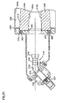
- Fig. 11 is an enlarged fragmentary portion of Fig. 4 , particularly a portion related to the lowest member 67 of the pulse jet assembly, shown in Fig. 4 .
- Fig. 10 is an enlarged fragmentary cross-sectional view of the assembly 1, the cross-sectional view being taken perpendicularly to the height dimension of the cartridge 15, Fig. 11 .
- Fig. 10 one can view the cartridge 15 within barrier filter stage 6, sealed against wall 6e. In particular portions of cartridge sections 55 and 56 are viewable, along with open end piece 52. In Fig. 10 , one can view portions of gasket arrangement 63 compressed against end wall 6e, with compression stop arrangement 63a limiting compression toward wall 6e.
- air flow aperture 60 in open end piece 52 is viewable.
- Aperture 60 provides for: (a) filtered air exit from cartridge 15 during normal filtering operation; and, (b) pulse jet entry into cartridge 15, from pulse jet arrangement 18, during a pulse jet cleaning operation.
- accumulator 35 is viewable in cross-section, and thus interior 35a can be seen.
- compressed air would be collected within accumulator interior 35a, to be directed through pulse jet arrangement 18 into cartridge 15, selectively, during operation.
- the pulse jet operation is controlled by valve arrangement 37, as mentioned above.
- the accumulator 35 comprises a tubular construction.
- an interior 35a of the tubular accumulator 35 has a generally circular cross-section, although alternatives are possible.
- Valve 37 is generally positioned at an opposite side 35x of accumulator 35 from cartridge 15.
- Gas exit tube 70 is shown extending through interior 35a, from valve 37 to gas exit nozzle 43.
- Valve 37 is configured to selectively allow a pulse of compressed air to be fed from interior 35a into interior 70a of tube 70, during operation. It is noted that tube 70 is shown with a curved shape, rather than a straight tubular shape.
- a somewhat “z” or “s” curved shape is formed with two, opposite, curved sections 70x, 70y, with tube 70 terminating in a nozzle 43 aligned with exit aperture 60.
- the example shows a tube 70 having more than one curve or bend 70x, y therein, forming a air flow conduit for flow of compressed air to nozzle 43.
- a straight tube could be used, as the flow conduit.
- a single curve in tube 70 could be used, as described in connection with other figures shown below. In still further arrangements, more than two curves could be used.
- Nozzle 43 is an end of tube 70, from which a gas pulse exits tube interior 70a and is directed to splitter 44.
- Splitter 44 is configured to selectively and desirably direct the pulse jet through aperture 60 and down internal region 15a of cartridge 15. The pulse jet would be directed into one of the cartridge sections 15a-15d, Fig. 4 , selectively. The particular example shown in Figs. 10 and 11 , would direct the pulse into chamber 15d.
- a splitter 44 provides for an appropriate dispersion of the pulse jet pressure, along the internal surfaces of the panels 55, 56, within an interior 15 of an associated cartridge chamber 15a-15d. It is important that the pulse jet be distributed appropriately along the length and height of each cartridge section 15a-15d, to achieve desirable pulse jet cleaning affects. These are controlled by: the force of the jet pulse, the time (duration) of the jet pulse, and, the size, configuration and position of: nozzle arrangement 43 and splitter 44.
- Fig. 11 a cross-sectional view orthogonal to the view of Fig. 10 is shown.
- dimension LL indicates the distance of splitter 44 from inlet aperture 60; and dimension MM indicates the distance of splitter 44 from exterior 6dx of wall section 6e.
- the splitter 44 (with vane 80) is spaced from the cartridge aperture 60 a distance LL within the range of 3-6 inches, inclusive (76.2 - 152.4 mm). The distance can be optimized for a given splitter and air filter cartridge.
- the operating pressure within chamber 35a would be about 100 psi; and, the time of each pulse would be about 100 milliseconds (0.1 sec).
- Fig. 12 Attention is first directed to Fig. 12 .
- Fig. 12 the view is toward nozzle 43 and splitter 44, from the position of the cartridge 15. Alternately stated, the view would be in direction of arrow 75, Fig. 11 .
- the splitter 44 includes a central splitter vane 80.
- the central splitter vane 80 includes a central aperture 81 and two sides 82, 83.
- the sides 82, 83 are joined at apex or vertex 85 which is directed toward the pulse jet.
- interior acute angle UU, Fig. 14 between the sides 82, 83 will generally be defined as the splitter angle.
- the splitter angle UU for typical assemblies according to the present disclosure, is typically within the range of 50° - 80°, inclusive.
- angle UU is 55° - 65°, inclusive; for example 60°.
- the central aperture 81 is generally an oblong aperture in a central portion of vane 80, with a portion 81 a, Fig. 12 , of the aperture 81 along or through side 82 and another portion 81 b along or through side 83, the aperture thus extending across apex or vertex 85. Alternate shaped apertures may be used.
- the length of the aperture 81 can be determined from Fig. 13 as 2 x dimension QQ. For the example shown, dimension W, Fig. 14 , is 2.0 inch (50.8 mm).
- the typical distance QQ, Fig. 13 of extension of the air flow aperture 81 along each side 82, 83, from the apex or vertex 85, is within the range of 0.55 - 0.80 inches (14 - 20.3 mm), inclusive; and, the maximum width dimension, where the air flow aperture 81 engages the vertex 85, is typically within the range of 0.33 - 0.43 inches (8.4 - 10.9 mm).
- the air flow aperture 81 is at its widest, when it crosses the vertex 85.
- the aperture 81 is generally rectangular shaped aperture 81 through a piece defining splitter vane 80, before bent to provide angle UU.
- the aperture 81 has rounded ends, and is oval in shape with parallel sides between the rounded ends.
- a jet pulse is received outwardly from nozzle 43 it is directed into splitter 44.
- a portion of the jet pulse will be split at apex 85, to extend above vane 82 and below vane 83. This will help distribute the pulse jet within an interior region 15i (or subchamber) of filter cartridge 15, Fig. 10 into which a jet pulse is directed.
- Another portion of the jet pulse will pass through aperture 81, as a narrow pulse, directed down the length of the associated chamber within cartridge 15.
- the particular splitter 44 definition provided in Figs. 12-15 provides for a good distribution of air as part of the jet pulse through a tall narrow aperture into cartridge 15, Fig. 10 , and also through a relatively long cartridge 15.
- nozzle 43 is depicted.
- the nozzle 43 has a generally rectangular outlet 43a. This facilitates a jet pulse entering the splitter 44, Fig. 12 in a preferred manner.
- the rectangular aperture 43a is preferably oriented with a longer dimension of the opening oriented perpendicular to the extension. This can be seen in Fig. 12 .
- tube 70 can be configured to gradually conform, in cross-section, from a circular cross-section to the rectangular outlet 43a, over a transition zone 43b.
- the splitter 44 includes side walls 88, 89 which enclose the vane 80 on opposite sides and which diverge from one another, typically at an angle RR of at least 15° and not greater than 35°, for example 15° to 35°, inclusive.
- angle RR 19°.
- the diverging side walls 88, 89 help shape the pulse jet into a form that is expanding in width as it enters the cartridge 15, to force air through the panels 55, 56.
- Definition of the splitter arrangement 44 and the nozzle 43 can be important, with respect to obtaining desirable operation for any given shaped and dimensioned cartridge. It can be optimized, empirically, for a system through experimental evaluation. For example appropriate transducers to detect the air pulse can be positioned at various places along a test cartridge, to evaluate pulse jet nozzles and splitters with different shapes.
- the assembly or system 1 includes a scavenger system or arrangement 11, for scavenging dust removed in the precleaner 5 and the barrier filter stage 6. Removal of dust or particulates from the precleaner 5 is shown provided by upper scavenge arrangement 11a, and removal of dust or other particulates from the barrier stage 6, is shown by lower scavenge section 22.
- the scavenge system 11 is generally operated by blower 25.
- the lower scavenge 22 is configured for convenient and efficient dust or other particulate removal. This will be understood by reference to Figs. 16-18 .
- scavenger arrangement 11 is depicted schematically and is shown separated from a remainder of assembly 1.
- upper scavenge section or portion 11a is viewable, as well as lower scavenge or scavenge portion 22.
- the upper scavenge portion 11a comprises two, spaced, upwardly projecting tubes 95 which extend from lower scavenge portion 22 upwardly through barrier filter section 6 into precleaner 5, Fig. 1 .
- a top plan view of the scavenge arrangement 11 is depicted, providing a view of upper surface 22a of lower scavenge portion 22. (An alternate to the arrangement of Fig. 17 being shown in Fig. 17A .)
- lower scavenge 22 provides a bottom floor to barrier filter section 6, Fig. 1 .
- End 96 is generally adjacent wall 6e, Fig. 1 , to which media pack 15 is sealed, during use.
- the pulse jet assembly 18, would be operated to provide pulse jet of air into a cartridge 15, Fig. 1 ,, at a location above end wall 96, Fig. 17 .
- lower scavenge duct portion 22 includes a scavenge aperture arrangement 100 therein.
- the scavenge aperture arrangement 100 comprises an aperture arrangement or pattern through an upper surface 22a of lower scavenge duct 22.
- This scavenge aperture arrangement 100 allows for passage of air and particulate, drawn from barrier filter region 6, Fig. 1 , into the scavenge system 11.
- aperture arrangement 100 comprises a first aperture arrangement 101 and a second aperture arrangement 102 oriented adjacent, and spaced from, opposite sides 98, 99, respectively and positioned such that a cartridge 15, Fig. 1 , operably positioned on surface 22, Fig. 17 , would generally be positioned between the aperture arrangements 101, 102 and would not be positioned to cover or overlap aperture arrangements 101, 102.
- the distance between the first and second ends 96, 97 of the housing bottom 22a will sometimes be referenced as distance BBB.
- the total open area of aperture arrangement 100 will generally be referred to as open area X, with a total open area of the first aperture arrangement 101 being total open area X 1 and the total open area of the second aperture arrangement 102 being total open area X 2 .
- X 1 X 2
- the distance between sides 98, 99 is referenced as AAA
- dimension BBB is 22.8 inches (57.9 cm); and, dimension AAA is 7.52 inches (19.1 cm). Alternatives are possible.
- the first scavenger aperture arrangement 101 will have a total open area X 1 to be configured such that at least 90% of the total open area X 1 is located within a distance of 60%, typically within a distance of 50%, of the distance (BBB) across the housing bottom 22 from the housing bottom first end 96 toward the second end 97. That is, at least 90% of the total area of aperture that comprises X 1 , is located, typically, within the half of surface 22 toward end 96 (with a more broad statement within 60% of the surface of bottom 22 toward end 96).
- the second scavenger aperture arrangement 102 will have a second total open area X 2 and be configured such that at least 90% of the open area X 2 is also located within a distance of 60%, typically within 50% of the distance (BBB) across the housing bottom 22 from the housing bottom first end 96.
- the aperture arrangements will be configured such that the first scavenger aperture arrangement 101 is such that 100% of the open area X 1 is located within a distance of 60%, typically within 50%, of the distance (BBB) across the housing bottom from the housing bottom first end 96; and, the second scavenge aperture arrangement will be configured to have a total open area X 2 and to be positioned such that 100% of the open area X 2 is located within a distance of 60%, typically within 50%, of the distance (BBB) across the housing bottom from the housing bottom first end 96.
- the first aperture arrangement 101 depicted comprises two types of apertures: a first, elongate aperture 101 a and a plurality of spaced, smaller apertures 101 b.
- the apertures of aperture arrangement 101 are positioned on a line extending from end 96 toward end 97 and parallel to sides 98, 99.
- the first elongate aperture 101a typically has an aspect ratio (length to width) of at least 5 and usually within the range of 5-10, inclusive, in some instances 7-10, inclusive, although alternatives are possible.
- the aperture 101 a typically also has a total open cross-sectional area corresponding to at least 30% of X 1 , usually at least 35% of X 1 , and for the example shown at least 50% of X 1 , although again, alternatives are possible.
- the elongate aperture 101a is positioned closer to wall 96 than are the remaining apertures 101b.
- the elongate aperture 101a is positioned at a location spaced from wall 96 within a distance of 25% of the distance from wall 96 to wall 97 (i.e., 25% of dimension BBB).
- aperture pattern 102 is similar to aperture pattern 101, in typical arrangements. Of course, alternatives are possible.
- the aperture pattern shown for aperture arrangement 101 provides that the highest volume of draw through surface 22a, will be in region relatively close to end 96. Referring to Fig. 1 this means that the maximum draw into scavenge 22 will generally be adjacent outlet end 52, of cartridge 15.
- This configuration provides several advantages. First, air flow through barrier region 6 will be generally down and toward end wall 6e, as shown by arrows 110, Fig. 1 . Thus, dust will tend to accumulate around cartridge 15 near wall 6e. The largest amount of draw into lower scavenger arrangement 22 occurs near the location where most dust build up will occur.
- the dust take-off 25a of blower 25, Fig. 1 occurs in a region of lower scavenger arrangement 22 adjacent end 96; i.e., closer to end 96 than end 97. This too is advantageous, at least since it ensures highest vacuum draw for the scavenge arrangement 11, occurs in the region of lower scavenger arrangement 22 where aperture arrangement 100 is located, and most dust build up, again, occurs.
- Fig. 17A is a view analogous to Fig. 17 , but showing an alternate scavenger aperture arrangement.
- reference numeral 422 indicates a lower scavenge portion corresponding generally to scavenge portion 22, Fig. 17 , discussed above.
- Lower scavenge portion 422 comprises: opposite ends 496, 497 and opposite sides 498, 499.
- End 496 is generally adjacent wall 6e, Fig. 1 , to which media pack 15 is sealed, during use.
- pulse jet assembly 18 would be operated to provide a pulse jet of air into a cartridge 15, Fig. 1 , at a location above end wall 496, Fig. 17A .
- lower scavenger duct portion 422 includes scavenge aperture arrangement 500 thereon.
- the scavenge aperture arrangement 500 comprises an aperture arrangement or pattern through an upper surface 422a of lower scavenge duct 422.
- the scavenge aperture arrangement 500 allows for passage of air in particulate, drawn from barrier filter region 6, Fig. 1 , into the scavenge system 11.
- aperture arrangement 500 comprises a first aperture arrangement 501 and a second aperture arrangement 502 oriented adjacent and spaced from opposite sides 498, 499 respectively, and positioned such that cartridge 15, Fig. 1 , positioned on surface 422, Fig. 17A , would be positioned between the aperture arrangements 501, 502 and would not be positioned to cover overlap aperture arrangements 501, 502.
- the distance between the first and second ends 496, 497 of the housing bottom 422a is sometimes referenced as distance BBB (or A7 as shown in Fig. 17A ).
- the total open area of aperture arrangement 500 will generally be referred to as open X, with a total open area of the first aperture arrangement 501 being a total open area X 1 and a total open area of the second aperture arrangement 502 being a total area X 2 .
- X 1 X 2
- the distance between the opposite sides 498, 499 is referenced herein as AAA (or A4 as shown in Fig. 17A ).
- first scavenger aperture arrangement 501 will have a total open area X 1 to be configured such that at least 90% of the total open area X 1 is located within distance of 60%, typically 50%, of the distance (A7 or BBB) across the housing bottom 422 from the housing bottom first end 496 toward the second end 497. That is, at least 90% of the total area of aperture that comprises X 1 , is located, typically, within the half of surface 422 toward end 496 (with a more broad statement being within 60% of the surface of bottom 422 toward end 496).
- second scavenger arrangement 502 has a second open area X 2 and is configured such that at least 90% of the open area X 2 is located within a distance of 60%, typically within 50%, of the distance (A7 or BBB) across the housing bottom 422 from the housing bottom first end 496.
- the scavenge aperture arrangement of Fig. 17A is a modification of the arrangement shown in Fig. 17 , and as with the arrangements previously discussed, usually aperture arrangements will be configured such that the first scavenge aperture arrangement 501 is such that 100% of the open area X 1 is located within a distance of 60%, typically within 50%, of the distance (A7 or BBB) across the housing bottom from the housing bottom first end 496; and, second scavenger aperture arrangement is configured to have a total open area X 2 and to be positioned that such 100% of the open area X 2 is within a distance of 60%, typically within 50%, of the distance (A7 or BBB) across a housing bottom from the housing bottom first end 496.
- the first aperture arrangement 501 is shown having two types of apertures: a first elongate aperture 501 a and a plurality of spaced, smaller apertures 501 b. Unlike the arrangement of Fig. 17 , the apertures of the aperture arrangement 501 are not positioned with all apertures on a single line extending from end 496 toward end 497 in parallel to sides 498, 499. For the particular aperture arrangement 501 depicted, there is a first elongated aperture 501a and a plurality of spaced, circular apertures 502b, although alternatives are possible.
- the first elongate aperture 501a similar to aperture arrangement 101 a discussed above, typically has an aspect ratio (length to width) of at least 5, and typically within the range of 5-10 inclusive, although alternatives are possible.
- the aperture 501a typically has a total open cross-sectional area corresponding to at least 35% of X 1 , typically up to 45%-60%, inclusive of X 1 , although alternatives are possible.
- the smaller aperture arrangement 501 b comprises two types of apertures: a first set 501 c of larger apertures oriented adjacent and spaced from elongate aperture 501 a, with the apertures of said 501 c being on a same line as elongate aperture 501a. And, a second set 501d of smaller apertures which includes some apertures on the line and some off set from the line defined by elongate aperture 501 a and aperture set 501c. Referring to set 501c, off set apertures are indicated individually at 501 e. The apertures 501 e are off set from the previously defined line, toward a center of surface 422a, in particular they would be positioned toward a filter cartridge 15, Fig.
- the elongate aperture 501 a is typically positioned closer to wall 496 than are the remaining apertures 501 b.
- the elongate aperture 501 a is positioned at a location spaced from the wall 496 within a distance of 25% of the distance from wall 496 to wall 497 (i.e., 25% of dimension A7 or BBB).
- aperture pattern 502 is similar to aperture pattern 501, in typical arrangements. Of course alternatives are possible.
- Fig. 1 flow through housing 6, Fig. 1 , is in the general direction shown at arrows 110.
- the flow has both a downward component and a component toward wall 6e.
- the downward component provides that while the dust tends to move toward end 6e, some become settled on surface 422a in the region of apertures of the aperture set 501 d.
- the scavenge pattern of Fig. 17A by comparison to the pattern of Fig. 17 , can better accommodate scavenge.
- the assembly 1 will include a serviceable filter cartridge retention and lock arrangement, for positioning the filter cartridge 15, Fig. 1 , properly within the barrier filter section 6, during use.
- the system will ensure that the cartridge 15 is maintained in appropriate position, and maintained under seal, during operation of assembly 1.
- Fig. 1 to facilitate viewing of internal componentry in assembly 1, the assembly 1 is depicted schematically, and features depicting a retention and lock arrangement for the cartridge 15, are not shown. Such features are shown, however, in Figs. 19-22 . It will be understood that the retention and lock assembly of Figs. 19-22 , would typically be used inside of the barrier filter region 6, Fig. 1 , as described.
- barrier filter section 6 is shown in side elevational view, with a side wall facing the viewer removed, for viewing of internal detail.
- Cartridge 15 is depicted within interior 6a of barrier section 6.
- the cartridge 15 is positioned to be sealed against wall 6e.
- the cartridge 15 is generally as shown in Figs. 5-9 .
- the filter cartridge biasing and lock arrangement is indicated generally at 120 and includes actuator handle 121 and biasing arrangement 122.
- the filter cartridge biasing and lock arrangement 120 is generally configured to bias the cartridge 15 under pressure in the direction of arrow 125, to facilitate sealing against wall 6e.
- the biasing in the direction of wall 125 is generally actuated by moving actuator 121 in a general direction of arrow 126, through a downward arc.
- the biasing lock arrangement 120 is shown in a generally unlocked orientation. As a result the cartridge 15 can be lifted out of barrier section 6, in the direction of arrow 128, by handle 61.
- handle 61 would typically be made to collapse, during installation, and to be extended as shown in Fig. 19 , during manipulation.
- Fig. 20 a top plan of the assembly portions of Fig. 19 .
- Fig. 19 the assembly is shown with the precleaner 5 removed, to allow access to interior 6a of section 6, thus to provide for servicing of cartridge 15.
- FIGs. 21 and 22 portions of the assembly 1 depicted in Figs. 19 and 20 are shown with the filter cartridge biasing and lock arrangement 120 in a locked orientation, i.e., handle 121 has been lowered. It is noted that the filter cartridge 15 is now biased securely into an operational sealed orientation, by being biased in the direction of arrow 125, Fig. 21 , against wall 6e. Handle 61 is still shown in an open or extended position, but in many instances it would easily have been collapsed prior to lowering of handle 121. It will be understood that when a precleaner 5, Fig. 1 , is positioned over top 6c, handle 121 will be secured in a locked position shown in Fig. 21 . In particular, and referring to Fig.
- handle 121 includes end projection 121a thereon, which projects upwardly from cartridge 15 when the handle 121 is lowered.
- the projection 121a is sized to fit between the cartridge 15 and the precleaner 5 (when in position) to inhibit cartridge 15 from unintended vertical movement when installed for operation.
- the biasing lock arrangement 120 will be configured so that biasing and locking of the cartridge 15 with sealing pressure in the direction of arrow 125 will be maintained, as long as the handle 121 is in the lowered position, Fig. 21 . Pressure of biasing would be relieved, when the handle 121 is lifted.
- end piece 51 is shown with a central recess or notch 130 therein, to receive a portion of the handle 121, Fig. 21 , as it is lowered.
- the notch 130 permits the handle 121 to be completely lowered, and also provides for engagement to ensure proper alignment, during assembly.
- a second, opposite, notch 130a could be provided as shown in bottom 59.
- Fig. 22 is a top plan view of the arrangement of Fig. 21 .
- the reference numeral 201 generally indicates a second air cleaner assembly including selected features according to the present disclosure.
- the air cleaner assembly 201 comprises a precleaner stage 205 and a barrier filter stage 206.
- assembly 201 is shown with a side panel facing the viewer removed, so that selected internal structure can be viewed.
- Fig. 23 is schematic.
- the precleaner stage 205 is positioned adjacent, i.e., on an end of the barrier filter stage 206, although alternatives are possible in alternate assemblies using the selected principles according to the present disclosure. (For example, in the assembly of Fig. 1 , the precleaner stage 5 was positioned above the barrier filter stage 6.)
- precleaner stage 205 In operation, air enters precleaner stage 205 in the direction indicated by arrows 210.
- the precleaner stage 205 would typically comprise a frame or housing including a plurality of cyclonic separators, similarly to precleaner stage 5, Fig. 1 . Separated particulates (dust) would be removed from precleaner 205 by precleaner scavenger portion 211 a of scavenger system 211. Air from the precleaner stage 205 is then directed into interior 206a of barrier filter stage 206.
- Service access to interior 206a of barrier filter stage 206 can be provided in several manners.
- barrier filter stage 206 would be provided with a removable cover at top 206c to provide access to interior 206a.
- precleaner 205 could be removable, to provide service access into interior 206a.
- the barrier filter stage 206 can be viewed as comprising a housing 206b having a top 206c, bottom 206d, an air flow outlet end 206e and opposite second end 206f. There is also provided a side panel 206g, Fig. 24 and an opposite side panel, removed for viewing in Fig. 23 but shown generally in Fig. 24 at 206h. As a result, barrier filter stage 206 can be viewed as a sub housing or a barrier filter housing.
- Serviceable filter cartridge 215 is operably positioned within interior 206a of barrier filter stage 206.
- the typical filter cartridge 215 has a v-pack shape, similarly to filter cartridge 15, Figs. 1 and 5-9 .
- the particular filter cartridge 215 depicted for the example shown also has unique specific v-pack filter dimensions and configurations discussed in greater detail below.
- Filter cartridge 215 is also configured for "out-to-in" flow, during filtering.
- the assembly 201 also includes a pulse jet assembly or arrangement 218.
- the pulse jet assembly or arrangement 218 is also configured to direct selected jet pulses of air through the filter cartridge 215, in a direction generally opposite to normal filtering flow, i.e., directed in-to-out with respect to direction of flow through the media.
- Such jet pulses can be directed to knock affected dust or other particulates off of the exterior of the filter cartridge 215, and into bottom region 220 of barrier filter stage 206. From there the dust or other particulates is removed by a barrier filter stage scavenge or scavenger 222 of scavenger system 211.
- a blower arrangement, 223, Fig. 23 would be used for operation of the precleaner scavenge portion 211a and first stage scavenge portion 222.
- air which is filtered by passage through filter cartridge 215 is generally directed into clean air plenum 230. From there, it can be directed to a turbo intake, engine intake, etc., as needed and appropriate for the system involved.
- FIG. 24 it is noted that the particular assembly 201 depicted, is configured to receive and utilize a single V pack filter cartridge 215. Principles according to the present disclosure could be applied in alternate arrangements, which include more than one serviceable filter cartridge.
- Fig. 24A is a view analogous to Fig. 24 , but depicts an alternate pattern for scavenge apertures. The alternate pattern is discussed further below, in connection with description of Fig. 38A .
- FIG. 25 an enlarged schematic, side cross-sectional view of a portion of the assembly in Fig. 23 is shown. Here a portion of interior structure in the air cleaner assembly 201 is depicted. The view depicts the pulse jet arrangement 218 as comprising nozzle and splitter arrangements 237 described below, to clean the v-pack arrangement.
- the pulse jet arrangement 218 would generally comprise valve arrangements 236 and accumulator 235.
- valve arrangement 236 comprises four valves 236a, although alternate arrangements and an alternate number of valves could be used.
- the four valves 236a are arranged in a vertical stack as shown.
- valves 236a control direction of pulse jets of air from accumulator 235 through nozzles 243 and splitters 244.
- nozzles 243 and splitters 244 For the assembly shown there are four nozzles 243 and four splitters 244, one each associated with each valve 236a.
- a portion of barrier filter stage 206 is viewable with serviceable filter cartridge 215 positioned therein.
- the cross-section of Fig. 25 is taken through the center of the filter cartridge 215. It can be seen that the filter cartridge 215 is divided, in this instance vertically, into multiple sections or stages. The number of sections or stages, is a matter of choice depending on the particular air cleaner, system and cartridge configuration involved. Typically there will be at least two, usually at least three sections or stages, typically not more than five, although alternatives are possible.
- the particular cartridge 215 depicted comprises four sections or stages 215a, 215b, 215c and 215d, each separated from the next adjacent one(s), by internal barriers 248. From Fig. 25 , it can be seen that each splitter 244 is positioned to direct air into one each of the chambers 215a-215d.
- the cartridge 215 is positioned so that the sections or stages 215a - 215d are stacked vertically on one another. This will be typical.
- the serviceable cartridge 215 is depicted in detail, in Figs. 26-30 .
- a top perspective view of the serviceable cartridge 215 is provided.
- the cartridge 215 comprises: v-pack panel arrangement 250; a closed narrow end cover 251; and, an open air outlet end piece 252.
- the closed cover 251 is positioned at a narrow end of the v-pack panel arrangement 250 and the open end piece 252 is positioned at a wide end of the v-pack panel arrangement 250.
- the cartridge 215 also includes top and bottom covers 258, 259.
- v-pack panel arrangement 250 comprises first and second panels 255, 256.
- Each panel 255, 256 typically comprises a panel of barrier media, for example pleated media. Typically when the media is pleated, it is positioned within cartridge 215 such that a longitudinal extension of the pleats is directed between top and bottom pieces 258, 259.
- Angle HHH is typically at least 4° and not greater than 10°, usually 5-7°, inclusive. For the example shown it is 5.76°.
- cartridge 215 is depicted in side elevational view.
- dividers 248, discussed above in connection with Fig. 25 are shown.
- the dividers 248 would not typically be viewable in a side elevational view, since panel 256 would block the view.
- cartridge 215 is fit with a top cover 258 and a bottom cover 259, which enclose the cartridges 255, 256.
- the media would be provided in a pleated form, in a frame. Two framed sections of pleated media would be used to form the side panels 255, 256. These two framed pieces would be fitted with top cover 258, bottom cover 259, closed end piece 251 and open end piece 252, to form cartridge 215.
- Fig. 27 is an end view of cartridge 215, the view being generally taken toward open end piece 252.
- Fig. 27 one can view through opening 260 into interior 260a of cartridge 215.
- Dividers 248 are now viewable.
- Aperture 260 is a tall, narrow, opening.
- the aspect ratio (height to width) of the opening is at least 0.06, within the range of 0.07 - 0.14, and not more than 0.17.
- the dividers 248 are evenly spaced along the height dimension, although alternatives are possible. In the example shown, the spacing between the divider 48 is indicated at dimension KKK as 5.95 inch (151 mm).
- Fig. 30 is a cross-sectional view taken along line 30-30, Fig. 26 .
- the top piece 258, bottom piece 259, panels 255, 256 and dividers 248 are readily viewable. Also viewable is pleated media 255a, 256a in each of the panels 255, 256.
- a top perspective view of cartridge 215 is presented. Attention is directed to handle arrangement 261.
- Handle arrangement 261 is provided on top piece 258, to facilitate lifting of the cartridge 215.
- the handle arrangement 261 can have a variety of constructions, and is typically made collapsible, so it can be lowered when not in use.
- the particular handle arrangement 261 depicted comprises a loop handle that can fold over, as shown, when not in use.
- the loop would typically be sized for extension therethrough of a human hand, in some instances a gloved hand, for example in some instances it may be large enough to be grasped by a person's hand wearing an arctic glove. This will in part be a matter of choice for the application involved.
- bottom piece 259 can be configured to include a similar handle.
- the cartridge 215, can, if desired, be manufactured with appropriate symmetry to be installed with either piece 258 or piece 259 positioned above the remainder of the cartridge 215, during assembly.
- the cartridge 215 could be specifically manufactured without symmetry, so that it can only be properly inserted into (and be operably installed in) the filter stage or housing 206, in one vertical orientation. When this is done, typically a handle would not be provided in the bottom cover piece 259.
- End piece 252 can be provided with a gasket arrangement, to provide a seal, as is cartridge 15, Fig. 9 . Indeed it could be provided with a gasket and compression stop arrangement, as is cartridge 15, Fig. 9 . However, for the particular assembly depicted, end piece 252 is provided with a raised rib 263 thereon. The rib 263 is sized to press into a gasket positioned in housing wall 206e, during assembly, to form a seal.
- example dimensions for an example useable cartridge 215 are provided.
- a pulse jet sequencing is from top to bottom.
- chamber 215a is initially pulsed by pulse jet 264, then chamber 215b by pulse jet 265, then chamber 215c by pulse jet 266 and then chamber 215d by pulse jet 267.
- This top to bottom pulse jet sequencing facilitates pushing contamination within chamber 206 down to bottom 220, for scavenge.
- Fig. 31 is a fragmentary view of the assembly 201, the cross-sectional view being taken perpendicularly to the height dimension of the cartridge 215, Fig. 32 .
- Fig. 32 is an enlarged fragmentary cross-sectional view of a portion of Fig. 25 , particularly a portion related to the lowest member of the pulse jet assembly, shown in Fig. 25 .
- Fig. 31 one can view the cartridge 215 within barrier filter stage 206, sealed against wall 206e. In particular, one can see a portion of projection 263 pressed into gasket 270, received in a portion of wall 206e. This detail is also viewable in Fig. 32 .
- Aperture 260 in open end piece 252 is viewable in Fig. 31 .
- Aperture 260 provides for: (a) filtered air exit from cartridge 215 during normal filtering operation; and, (b) pulse jet entry into cartridge 215, from pulse jet arrangement 218, during a pulse jet cleaning operation.
- gas exit tube 270 is shown extending from valve 237 to nozzle 243.
- Valve 237 is configured to selectively allow a pulse of compressed air to be fed into interior 270a of tube 270, during operation.
- tube 270 is shown with a bent shape, rather than a straight tubular shape. In particular a single bend 270b is provided to form an open "L" shape is shown.
- Nozzle 243 is at an end of tube 270, from which a gas pulse exits tube interior 270a and is directed to splitter 244.
- Splitter 244 is configured to selectively and desirably direct the pulse jet through aperture 260 and down internal region 260a of cartridge 215.
- the pulse jet would be directed into one of the cartridge sections 215a-215d, Fig. 25 , selectively.
- the particular example shown in Figs. 31 and 32 would direct the pulse into chamber 215d.
- splitter 244 provides similar operation to splitter 44, Figs. 12-14 .
- dimension PPP indicates the distance of splitter 244 from inlet aperture 260; and dimension QQQ indicates the distance of splitter 244 from exterior 206x of wall section 206e.
- FIG. 33 Attention is first directed to Fig. 33 .
- Fig. 33 the view is toward nozzle 244, from the position of the cartridge 215. Alternately stated, the view would be in direction of arrow 275, Fig. 32 .
- the splitter 244 includes a central splitter vane 280.
- the central splitter vane 280 includes a central aperture 281 and two sides 282, 283.
- the sides 282, 283 are joined at vertex 285 which is directed toward the pulse jet.
- interior acute angle UUU, Fig. 34 between the sides 282, 283 will generally be defined as the splitter angle.
- the splitter angle UUU for typical assemblies according to the present disclosure was described earlier, as within the range of 50°-80° inclusive. Usually angle UUU is 60°, as shown for the assembly shown in Figs. 33-36 .
- the central aperture 281 is generally an oblong aperture in a central portion of vane 280, with a portion of the aperture being along side 282 and another portion along side 283, the aperture thus extending across vertex 285. Alternate shaped apertures may be used.
- a jet pulse is received outwardly from nozzle 243 it is directed into splitter 244.
- a portion of the jet pulse will be split at vertex 285, to extend above vane 282 and below vane 283. This will help distribute the pulse jet within an interior region or subchamber or filter cartridge 215 into which a pulse jet is directed.
- Another portion of the jet pulse will pass through aperture 281, Fig. 33 , as a narrow pulse, directed down the length of the associated chamber within cartridge 215.
- the particular splitter 244 definition provided in Figs. 33-35 provides for a good distribution of air as part of the jet pulse through a tall narrow aperture into cartridge 215, and also through a relatively long cartridge 215.
- nozzle 243 is depicted.
- the nozzle 243 has a generally circular outlet 243a. This is not necessarily an optimized shape. It is possible that performance could be improved by changing the nozzle shape 243a, to a shape similar to nozzle 43, Fig. 15 .
- the I.D. inside diameter
- the nozzle O.D. outside diameter
- the splitter 244 includes side walls 288, 289 which enclose the vane 280 on opposite sides and which diverge from one another, typically at an angle XXX, Fig. 35 , within the range described above for the previously described embodiment.
- XXX 29°.
- the diverging side walls 288, 289 help shape the pulse jet into a form that is expanding in width as it enters the cartridge 215, to force air through the panels 255, 256.
- the assembly or system 201 includes a scavenger system or arrangement 211, for scavenging dust removed in the precleaner 205 and the barrier filter stage 206. Removal of dust or particulates from the precleaner 205 is shown provided by precleaner scavenge arrangement 211a, and removal of dust or other particulates from the barrier stage 206, is shown by barrier filter scavenge section 222.
- the scavenge system 211 is generally operated by a blower, not shown.
- the scavenge 222 is configured for convenient and efficient dust or other particulate removal. This was shown in Figs. 23 and 23A and will be further understood by reference to Figs. 37-39 .
- a top plan view of the scavenge arrangement 211 is depicted, providing a view of upper surface 222a of scavenge portion 222.
- scavenge 222 provides a bottom portion to barrier filter section 206, Fig. 23 .
- scavenge portion 222 includes: opposite ends 296, 297; and, opposite sides 298, 299.
- End 296 is generally adjacent wall 206e, to which media pack 215 is sealed, during use.
- the pulse jet assembly 218, would be operated to provide pulse jet of air into a cartridge 215, Fig. 23 , at a location above end wall 296, Fig. 37 .
- scavenge 222 includes separate tubular sections 222b, 222c, as opposed to a single bottom surface. Of course alternatives are possible.
- scavenge duct portion 222 includes a scavenge aperture arrangement 300 therein.
- the scavenge aperture arrangement 300 comprises an aperture arrangement or pattern through an upper surface 222a of scavenge duct portion 222.
- This scavenge aperture arrangement 300 allows for passage of air and particulate, drawn from lower barrier filter region 206, Fig. 23 , into the scavenge system 211.
- aperture arrangement 300 comprises a first set of apertures 301 in duct 222b and a second set of apertures 302 in duct 222c, oriented adjacent, and spaced from, opposite sides 298, 299, respectively and positioned such that a cartridge 215, Fig. 23 , positioned on surface 222, Fig. 37 , would generally be positioned between the aperture arrangements 301, 302 and would not be positioned to cover or overlap the apertures of aperture arrangements 301, 302.
- Aperture arrangement 301 may be generally analogous to aperture arrangement 101, Fig. 17 , and aperture arrangement 302 may be generally analogous to aperture arrangement 102, Fig. 17 .
- an elongate aperture 301a is provided in aperture arrangement 301 positioned closer to wall 296 than are the remaining apertures 301 b.
- the aperture pattern shown for the aperture arrangements 301, 302 is analogous to the aperture pattern shown and discussed above with respect to Fig. 17 .
- Fig. 38A depicts a scavenger arrangement in accord with Fig. 24A and as an alternate to that depicted in Fig. 37 and 38 .
- scavenge 622 is depicted. Scavenge 622 would generally be used analogously to scavenge 222, discussed above.
- scavenge portion 622 includes: opposite ends 696, 697. End 696 is generally adjacent wall 206e, Fig. 23 , to which media pack 215 is sealed, during use.
- the pulse jet assembly 218, Fig. 23 would be operated to provide a pulse jet of air into the cartridge 215, Fig. 23 , at a location above end wall 696, Fig. 37 .
- scavenge 622 includes tubular sections 622b, 622c, as opposed to a single bottom surface. Of course alternatives are possible.
- scavenge duct portion 622 includes a scavenge aperture arrangement 700 therein.
- the scavenge aperture arrangement 700 comprises an aperture arrangement or pattern through an upper surface 622a of scavenge duct portion 622.
- the scavenge aperture arrangement 700 allows for passage of air in particular, drawn from the lower barrier filter region 206, Fig. 23 , into the scavenge system 211.
- aperture arrangement 700 comprises a first set of apertures 701 in duct 622b and a second set of apertures 702 in duct 622c, oriented adjacent, and spaced from, opposite sides 698, 699, respectively, and positioned such that a cartridge 215, Fig. 23 , positioned on surface 622, Fig. 37 , would generally be positioned between the aperture arrangements 701, 702 and would not be positioned to cover and overlap the apertures of aperture arrangement 701, 702.
- scavenge aperture arrangement 701 generally comprises two sets of apertures 701a and 701 b. Each set of apertures includes two elongate apertures and a plurality of spaced circular apertures.
- aperture arrangement 701 a comprises elongate aperture 701c and a plurality of spaced circular apertures 701 d.
- elongate aperture 701c would typically have an aspect ratio (length to width) of at least 5, typically within the range of 5-10, and would often comprise at least 30% typically at least 35% and often at least 50% of the total area of apertures in aperture set 701 a.
- Aperture set 701 b is positioned next to and spaced from aperture arrangement 701a.
- Aperture 701f, in set 701 b, is also an elongate aperture typically having an aspect ratio of at least 5, usually within the range of 5 to 10.
- Aperture arrangement 701 b further includes a plurality of spaced, in this instance circular, apertures 701 g.
- Elongate apertures 701 f typically and preferably comprises at least 30% usually at least 35% and in some instances at least 50% of the total aperture area of aperture arrangement 701 b.
- At least 90%, typically at least 100%, of the total open aperture area for each of aperture sets 701 a and 701 b is preferably positioned within a distance of extension between ends 696 and end 697, of no greater than 60% and typically no greater than 50% and usually no greater than 30%, from end 696 toward end 697.
- Aperture arrangement 702 is depicted in duct 622c.
- Aperture arrangement 702 may be analogous to aperture arrangement 701, and comprise a first set 702a and a second set 702b, of apertures.
- aperture set 701d for aperture pattern 701 a, the individual apertures of set 701d are positioned on a line that extends through aperture 701c and generally parallel to side 698 in extension from end 696 toward end 697.
- Aperture set 710g generally comprises individual apertures in a line that is angled relative to side 698, in extension from 696 toward end 697.
- the line on which apertures of set 710g are positioned is angled away from side 698 toward side 699, at an angle within the range of about 2 to 10°, in such extension.
- elongate aperture 701d and 701f can be characterized as positioned "side-by-side,” meaning that longer dimension of each is positioned adjacent the longer dimension of the other. The same can be said for the elongate apertures of aperture arrangement 702.
- each elongate aperture 701d, 701f of aperture arrangement 701 comprises at least 10% of the total aperture area of aperture arrangement 701, typically each comprising at least 15% and usually at least 20% of that area. The same would be said of the elongate apertures of aperture arrangement 702 with respect to the total aperture area of arrangement 702.
- each of the apertures 701d can be characterized as smaller than any of the elongate apertures (apertures 701c, 701f) of aperture arrangement 701. For the example shown, a similar statement can be made for the smaller apertures of aperture arrangement 702.
- Figs. 23-29 the assembly 201 and its components are depicted schematically. No specific cartridge retention and lock arrangement is shown. One could be provided in an analogous manner as for the assembly of Figs. 19-22 .
- a common feature of the two assemblies depicted is that for each a v-pack filter cartridge is provided comprising first and second panel sections arranged as the size of a v-configuration with a narrow end and a wide end.
- the first and second panel sections define an interior angle within the range of 5°-7°, inclusive. This means that the v-pack has a relatively narrow inside angle defining a narrow interior volume.
- the closed end piece is positioned over the narrow end of the v-configuration, and an open end piece is positioned over the wide end of the v-configuration.
- open in this context, it is meant that the open end piece includes an air flow aperture therethrough.
- the air flow aperture in the two arrangements depicted has a relatively narrow high aperture.
- the width to height ratio for each is typically within the range of 0.07 - 0.14, inclusive.
- Each filter cartridge is relatively long, typically having a length, between the open end piece and the closed end piece, within the range of 18-25 inches, inclusive (457 - 635 mm).
- the cartridges depicted each include top and bottom frame piece extending between the closed end piece and the open end piece, and positioning the first and second panel sections therebetween.
- at least one of the top and bottom frame pieces has a loop handle member thereon.
- the filter cartridges include at least one, typically at least two, and for the example shown, three, spaced dividers or divider plates positioned inside a v-pack, between the first and second panel sections. This divides the interior volume into at least two (and when three divider plates are used four) stacked regions positioned between the top and bottom frame pieces.
- the interior angle of the v-pack filter cartridge is within the range of 4°-10°, inclusive; more specifically 5°-7°, inclusive; and specifically within the range of 5.2°-5.9°, inclusive, and the width to height ratio for the air flow aperture is within the range of 0.08 - 0.13 inclusive.
- the v-pack filter cartridge is relatively high, typically having a dimension, corresponding to a distance between the top and bottom frame pieces, within the range of 24-27 inches, inclusive (609 - 686 mm).
- the loop handle arrangements are collapsible loop handle arrangements. Further, an option is described in which each of the top and bottom plates includes a loop handle arrangement.
- splitter arrangement configured for directing a pulse jet into a v-pack filter cartridge.
- the splitter arrangement is characterized as comprising a splitter vane having two sides joined at a vertex.
- the splitter vanes shown provide an interior angle within the range of 50°-80°, inclusive and include an air flow aperture therethrough, the air flow aperture extending across the vertex and having a portion standing through each of the two sides.
- the splitter vanes have an interior angle within the range of 55°-65°, inclusive, with the specific examples shown being 60°.
- the splitter arrangements described include first and second side wall pieces positioned with the splitter vane positioned therebetween and with a vertex extending between the side wall pieces.
- the first and second side wall pieces are configured to diverge outwardly from one another, in extension outwardly along the splitter vane, from the vertex; in the examples shown; the angle of divergence being within the range of 15°-35°, inclusive.
- the air flow aperture in the splitter vane extends, from the vertex, a distance along each vane side within the range of 0.55-0.80 inches, inclusive (14 - 20.3 mm) and the air flow aperture has a maximum width dimension, where it intersects the vertex, within the range of 0.33-0.43 inches, inclusive (8.4 - 10.9 mm).
- the typical aperture is somewhat oval in shape, with curved ends and straight sides, although alternatives are possible.
- an assembly including a v-pack filter cartridge operably positioned with respect to a pulse jet splitter arrangement.
- the v-pack filter cartridge is generally as described above, and the pulse jet splitter arrangement is generally as described above, although some variations are possible.
- each splitter arrangement is positioned with an end of the splitter vane remote from the vertex spaced a distance within the range of 3-6 inches, inclusive, (76 - 152 mm) from the air flow aperture in the v-pack filter cartridge and each splitter arrangement is positioned with a splitter vane oriented to split a portion of a pulse jet flow operably directed therethrough into a first flow portion directed toward the top frame piece of the v-pack filter cartridge, a second flow portion directed toward a bottom frame piece of the v-pack filter cartridge and a third flow portion directed through the air flow aperture in the splitter vane.
- This provides for a good pulse jet affect, in cleaning the associated v-pack chamber into which the pulse jet flow is directed.
- each of the assemblies involves a combination comprising a pulse jet splitter arrangement and nozzle for feeding a pulse jet flow into the pulse jet splitter arrangement.
- the combination comprises a splitter arrangement generally as described above.
- Each includes a nozzle having a nozzle exit aperture positioned for air flow into the vertex of the splitter vane.
- the nozzle exit aperture depicted is non-circular and has a long dimension and a narrow dimension.
- the nozzle exit aperture is positioned with a splitter vane vertex extending in a direction across the nozzle exit aperture in a direction of the narrow dimension and generally perpendicular to a direction of the long dimension.
- the second assembly described has a circular nozzle.
- the nozzle exit aperture has a wide dimension within the range of 0.5-0.65 inch (12.7 - 16.5 mm), inclusive and a longer or length dimension within the range of 1.4-1.6 inch, inclusive (35.6 - 40.6 mm).
- Each of the assemblies described includes a barrier filter stage comprising a combination of a v-pack filter cartridge positioned in a barrier filter housing including a scavenge arrangement therein.
- the v-pack filter cartridge includes features as described herein above for a typical v-pack filter cartridge, although it is not required that all features be present in all applications.
- a scavenge arrangement positioned in a bottom of the housing with a v-pack filter cartridge positioned thereon.
- the housing bottom can be characterized as having a first end and a second end separated by a distance Y, with the distance Y varying between the two assemblies depicted.
- the v-pack filter cartridge is positioned with the open end piece adjacent the housing bottom first end.
- the scavenge arrangement comprises first and second scavenge aperture arrangements.
- the v-pack filter cartridge is positioned in the housing bottom at a location between the first and second scavenge aperture arrangements.
- the first scavenge aperture arrangement can be described as having a first total open area X 1 and being configured such that at least 90% of the open area of the X 1 is located within a distance of 50% Y across the housing bottom from the housing bottom first end toward the housing bottom second end. Preferably 100% of the open area X 1 is located within 50% Y across the housing bottom from the housing bottom first end toward the housing bottom second end.
- a second scavenger aperture is similarly configured and positioned to the first scavenge aperture arrangement.
- Each of the scavenge aperture arrangements includes at least one elongate aperture having an aspect ratio (length to width ratio) of at least 5 and within the range of 5-10, inclusive. Also, in each instance the elongate aperture(s) is typically positioned within a distance of 25% Y across the housing bottom from the housing bottom first end toward the housing bottom second end. Some preferred arrangements are shown and described.
- each scavenge aperture arrangement comprises at least one elongate aperture and a plurality of smaller apertures. Several arrangements of smaller apertures are provided.
- each of the assemblies depicted includes, in association with the scavenge arrangement, a blower takeoff that is positioned generally adjacent the housing bottom first end, to help ensure that scavenge air flow through the scavenge arrangement, is generally in a direction from the housing bottom second end toward the housing bottom first end, a direction generally aligned with air flow during filtering through the housing.
- the scavenge air flow through the scavenge arrangement is along a path toward a location adjacent the wide, open, end of the v-pack from a location adjacent the narrow, closed, end of the v-pack.
- a unique pulse jet assembly which includes a compressed air accumulator having a tubular side wall, a pulse jet valve arrangement mounted on the tubular side wall; and a pulse jet flow conduit extending from the pulse jet valve arrangement through the compressed air accumulator and through the tubular side wall.
- the tubular side wall has a circular interior cross-sectional shape
- the pulse jet flow conduit has two curved sections therein, forming an "s" or "z" shape.
- the flow conduit has a transition portion from a region of generally circular cross-section to a flow outlet which is non-circular, and for the example shown generally rectangular with curved corners.
Landscapes
- Chemical & Material Sciences (AREA)
- Chemical Kinetics & Catalysis (AREA)
- Engineering & Computer Science (AREA)
- Physics & Mathematics (AREA)
- Geometry (AREA)
- Combustion & Propulsion (AREA)
- Mechanical Engineering (AREA)
- General Engineering & Computer Science (AREA)
- Filtering Of Dispersed Particles In Gases (AREA)
- Electrostatic Separation (AREA)
Abstract
Description
- The present disclosure relates to air cleaners. It particularly concerns features of air cleaner arrangements configured for pulse jet cleaning operation. Specific advantageous features, overall assemblies and methods are described.
- Various equipment is operated by internal combustion engines, such as diesel engines. Such equipment is often designed to be operated in particularly severe environments. Examples are: military vehicles such as tanks, armored vehicles or transport construction equipment; and, agricultural, construction and mining equipment. In such environments, combustion air drawn from the environment and directed into the engine, can contain substantial particulate contaminant therein. Air cleaners are used for removal of this contaminant. Typical air cleaners utilize a filter having filter media therein, through which the intake air is directed. Particulates are deposited on or in the filter media.
- In some instances, precleaners, for example cyclonic precleaners, are used before the air is directed into the barrier media. An example of such an arrangement is described in
U.S. 5,575,826 incorporated herein by reference. - In some instances, the filter media is contained within a serviceable filter cartridge. By the term "serviceable" in this context, it is meant that the filter cartridge is of a design that is to be removed from, and be replaced in, the air cleaner, in time.
- In order to extend the service lifetime for the filter cartridge, and to maintain equipment performance, in some instances it is desirable to provide for periodic cleaning of the serviceable filter cartridge, without removal of the serviceable filter cartridge from the air cleaner. This can be conducted with a pulse jet cleaning system. Examples of such systems are described in
U.S. 5,575,826 and6,676,721 , incorporated herein by reference. In general with such assemblies, pulse air flow is selectively intermittently directed through selected portions of a filter cartridge, to eject collected dust from the filter cartridge. The ejected dust falls to a bottom of the air cleaner, to be scavenged therefrom by a scavenge system. - Improvements in such assemblies are generally desirable.
- According to the present disclosure, selected pulse jet air cleaner systems and components and assemblies for use in pulse jet air cleaner systems are shown. The systems include features that provide for efficient pulse jet cleaning of cartridges that have fairly narrow long v-pack assemblies, for example. Also preferred scavenger arrangements or preferred features of scavenger arrangements are shown, for efficient scavenging of pulse jet air cleaners. A variety of specific, advantageous features for use in such assemblies are provided, as well as methods of use.
- It is not a requirement that all of the advantageous features described herein, be incorporated in any given pulse jet air cleaner system, for the air cleaner system to be provided with some advantage according to the present disclosure.
-
-
Fig. 1 is a schematic side elevational view of a first air cleaner system or assembly according to the present disclosure; the assembly inFig. 1 being shown with a side panel and certain other componentry removed, to provide a viewing of internal detail. -
Fig. 2 is an end elevational view of the assembly depicted inFig. 1 . -
Fig. 3 is a second end elevational view of the assembly depicted inFig. 1 ;Fig. 3 being toward an opposite end of that viewable inFig. 2 and showing the assembly with a precleaner removed. -
Fig. 4 is a cross-sectional view taken generally along line 4-4,Fig. 3 . -
Fig. 5 is a schematic top plan view of a serviceable filter cartridge useable in the assembly ofFigs. 1-4 . -
Fig. 6 is an end elevational view of the filter cartridge depicted inFig. 5 ; the view ofFig. 6 being toward an open end of the serviceable filter cartridge. -
Fig. 7 is a side elevational view of the cartridge depicted inFig. 5 , with phantom lines indicating selected internal detail. -
Fig. 8 is a schematic cross-sectional view taken along line 8-8,Fig. 5 . -
Fig. 9 is a top perspective view of the serviceable filter cartridge depicted inFigs. 5-8 . -
Fig. 10 is a fragmentary schematic cross-sectional view of a pulse jet assembly portion of the assembly depicted inFig. 1 ;Fig. 8 being taken generally orthogonal to the view ofFig. 11 . -
Fig. 11 is a schematic side cross-sectional view of a portion of the assembly depicted inFig. 3 . -
Fig. 12 is an exit end view of a splitter component of the pulse jet assembly depicted inFigs. 10 and11 . -
Fig. 13 is a top view of the splitter component depicted inFig. 12 . -
Fig. 14 is a side elevational view of the splitter component depicted inFig. 12 , with selected internal componentry depicted in phantom lines. -
Fig. 15 is a cross-sectional view of a nozzle component depicted in the pulse jet assembly ofFigs. 12-14 ,Fig. 15 being taken along 15-15 ofFig. 14 . -
Fig. 16 is a schematic side elevational view of a scavenge duct assembly for the air cleaner assembly ofFig. 1 . -
Fig. 17 is a top plan view of the scavenge duct assembly ofFig. 16 . -
Fig. 17A is a top plan view of the scavenge duct assembly ofFig. 16 , showing an alternate scavenge aperture arrangement toFig. 17 . -
Fig. 18 is an end elevational view of the scavenge duct assembly ofFig. 16 . -
Fig. 19 is a schematic side view of a biasing and lock mechanism positionable with the assembly ofFig. 1 and useable to secure a serviceable filter cartridge in position, in the assembly ofFig. 1 ; inFig. 19 the biasing and lock mechanism being shown in an unlocked orientation and with a filter cartridge operably positioned therein. -
Fig. 20 is a top plan view of the assembly shown inFig. 19 . -
Fig. 21 is a view analogous toFig. 19 , but showing the biasing and lock mechanism in a closed and locked orientation. -
Fig. 22 is a top plan view of the assembly shown inFig. 21 . -
Fig. 23 is a schematic side elevational view of a second air cleaner assembly according to a second embodiment of the present disclosure; the assembly ofFig. 23 being shown with a side panel removed to provide a viewing of internal detail. -
Fig. 24 is a top view of the assembly ofFig. 23 , with a cover removed to show internal detail. -
Fig. 24A is a top view analogous toFig. 24 , but showing an alternate scavenge aperture arrangement. -
Fig. 25 is an enlarged fragmentary view depicted in cross-section showing a pulse jet portion of the assembly depicted inFig. 23 . -
Fig. 26 is a top plan view of a serviceable filter cartridge used in the assembly ofFigs. 23 and24 . -
Fig. 27 is an end elevational view of the cartridge ofFig. 26 ; the view ofFig. 27 being toward an outlet end of the cartridge. -
Fig. 28 is a side elevational view of the cartridge ofFig. 26 , with phantom lines indicating internal divider structure. -
Fig. 29 is a perspective view of the filter cartridge ofFigs. 26-28 . -
Fig. 30 is a schematic cross-sectional view taken along line 30-30,Fig. 26 . -
Fig. 31 is an enlarged schematic cross-sectional view of selected componentry depicted in the assembly ofFig. 25 . -
Fig. 32 is a side view of the componentry depicted inFig. 31 . -
Fig. 33 is an end view of a splitter assembly useable in the componentry depicted inFig. 31 . -
Fig. 34 is a side view of the componentry depicted inFig. 33 . -
Fig. 35 is a top view of the componentry depicted inFigs. 33 and 34 . -
Fig. 36 is a cross-sectional view of a nozzle component of the componentry depicted inFigs. 33-35 ,Fig. 36 being taken along line 36-36,Fig. 34 . -
Fig. 37 is a top plan view of a scavenger arrangement for the assembly ofFig. 23 . -
Fig. 38 is an enlarged view of a portion ofFig. 37 . -
Fig. 38A is a view analogous toFig. 38 , but showing the alternate scavenge aperture arrangement ofFig. 24A . -
Fig. 39 is a side elevational view of a portion ofFig. 37 . - The
reference numeral 1,Fig. 1 , generally indicates an air cleaner assembly including selected features according to the present disclosure. The aircleaner assembly 1 comprises aprecleaner stage 5 and abarrier filter stage 6. InFig. 1 ,assembly 1 is shown with a side panel facing the viewer removed, so that selected internal structure can be viewed.Fig. 1 is schematic. For theparticular assembly 1 depicted, theprecleaner stage 5 is positioned above thebarrier stage 6, although alternatives are possible in alternate assemblies using the selected principles according to the present disclosure. - In operation, air enters
precleaner stage 5 in the direction indicated byarrow 10. Theprecleaner stage 5 would typically comprise a frame or housing including a plurality of cyclonic separators such as, for example, described inU.S. Patents 4,008,059 ;4,050,913 ;4,289,611 ;3,448,563 ;3,713,280 ;4,985,058 ; and,4,976,748 , the complete disclosures of these seven references being incorporated herein by reference. Such separators will generally cause separation of some dust or other particulate material under centrifugal force. The dust is then removed fromprecleaner stage 5, by upper orprecleaner scavenger portion 11 a ofscavenger system 11. Partially cleaned air from theprecleaner stage 5 is then directed into interior 6a ofbarrier filter stage 6. - For the example equipment depicted, the
precleaner 5 is removable frombarrier filter stage 6. In this manner service access is provided to an interior 6a ofbarrier filter stage 6, through an upper end provided whenprecleaner 5 is removed. Thebarrier filter stage 6 can be viewed as comprising ahousing 6b having: a top 6c, abottom 6d; a first airflow outlet end 6e; and opposite, second,end 6f. There is also providedside panel 6g and an opposite side panel, removed for viewing inFig. 1 but shown generally inFig. 2 at 6h. As a result,barrier filter stage 6 can be viewed as a sub housing or a barrier filter housing. - In
Fig. 1 ,serviceable filter cartridge 15 is operably positioned within interior 6a ofbarrier filter stage 6. Thetypical filter cartridge 15 has a v-pack shape described in greater detail below. Examples of v-packs but with different specific features are generally shown and described inU.S. Patents 6,676,721 and Des. 455,826, incorporated herein by reference. Theparticular filter cartridge 15 has certain unique v-pack filter dimensions and configurations discussed in greater detail below.Filter cartridge 15 is generally configured for "out-to-in" flow, during filtering. That means that the air flow would generally pass through filter media portions of thecartridge 15, in a direction from exterior 15x of thecartridge 15, to aninterior 15i,Fig. 9 , of thecartridge 15, during filtering. - The
assembly 1 includes a pulse jet assembly orarrangement 18. The pulse jet assembly orarrangement 18 is configured to direct selected jet pulses of air through thefilter cartridge 15, in a direction generally opposite to normal filtering flow, i.e., directed in-to-out with respect to direction of flow through the media. Such jet pulses can be directed to knock affected dust or other particulates off of the exterior 15x of thefilter cartridge 15, and intobottom region 20 ofbarrier filter stage 6. From here the dust or other particulates is removed by a barrier filter stage scavenge arrangement, orlower scavenger arrangement 22 ofscavenger system 11. A blower arrangement for operation of theupper scavenge portion 11a andlower scavenge arrangement 22 is indicated generally at 25, with the scavenger outlet or exhaust shown atarrow 26. A blower takeoff from thelower scavenge arrangement 22 is shown at 25a, at a location closer to end 6e thanend 6f. - Still referring to
Fig. 1 , air which is filtered by passage throughfilter cartridge 15 is generally directed intoclean air plenum 30. Referring toFig. 2 , the clean air passes from plenum 30 outwardly fromair cleaner 1, throughoutlet 31. From there, it can be directed to a turbo intake, engine intake, etc., as needed and appropriate for the system involved. - It is noted that the
particular assembly 1 depicted inFig. 1 is configured to receive and utilize a single v-pack filter cartridge 15. Principles according to the present disclosure could be applied in alternate arrangements, which include more than one v-filter filter cartridge. - In
Fig. 3 , an opposite end view to the end view ofFig. 2 is depicted. Here the aircleaner assembly 1 is depicted with theprecleaner stage 5 removed. Also,blower equipment 25,Fig. 1 , belowstage 6 is not shown. - The end view depicts the
pulse jet arrangement 18 as comprising anaccumulator 35 with a set ofvalve arrangements 36 thereon. Theaccumulator 35 comprises a compressor vessel for receiving compressed air from a compressor, for use in the pulse jet cleaning. Thevalve arrangements 36 provide for controlled pulse jets from theaccumulator 35 through a nozzle and splitter arrangement described below, to clean the v-pack arrangement. - For the particular air
cleaner assembly 1 depicted inFigs. 1-3 , thevalve arrangement 36 comprises fourvalves 37, although alternate arrangements and an alternate number of valves could be used. For the particular aircleaner assembly 1 depicted, the fourvalves 37 are arranged in a vertical stack as shown. - Attention is now directed to
Fig. 4 , a cross-section taken along 4-4,Fig. 3 . InFig. 4 , a compressed airflow inlet conduit 40 is depicted, for entering gas flow under pressure intoaccumulator 35. Also inFig. 4 , it can be seen that thevalves 37 control direction of pulse jets of air fromaccumulator 35 throughnozzles 43 andsplitters 44. For the assembly shown there are fournozzles 43 and foursplitters 44, one each associated with eachvalve 37. - Detail regarding the
nozzles 43 andsplitters 44 will be discussed below in connection with other figures. - In
Fig. 4 ,barrier filter stage 6 is viewable withserviceable filter cartridge 15 positioned therein. The cross-section ofFig. 4 , is taken through the center of thefilter cartridge 15. It can be seen that theinterior 15i offilter cartridge 15 is divided, in this instance vertically, into a stack of multiple sections or stages. The number of sections or stages is a matter of choice depending on the particular air cleaner, system and cartridge configuration involved. Typically there will be at least two sections or stages, often at least three and usually not more than five, although alternatives are possible. Theparticular cartridge 15 depicted comprises a stack of foursections stages internal barriers 48. FromFig. 4 , it can be seen that eachsplitter 44 is positioned to direct air into one each of thechambers 15a-15d. - It is noted that for the
assembly 1 shown, thecartridge 15 is positioned so that the sections orstages 15a - 15d are stacked vertically on one another. This will be typical for an assembly according to the present disclosure. - Typically, and referring to
Fig. 4 ,cartridge 15 is inserted or removed from interior 6a, by passage through upper end or top 6c ofbarrier filter stage 6, when theprecleaner assembly 5 is removed or opened. - In
Fig. 4 , dimension AA is depicted. Dimension AA may vary, from system to system. For the particular example shown, dimension AA is 1.2 inches (30.5 mm). - The
serviceable cartridge 15 is depicted in detail, inFigs. 5-9 . - In
Fig. 9 a top perspective view of theserviceable cartridge 15 is provided. Thecartridge 15 comprises v-pack panel arrangement 50, a closed narrow end piece or cover 51, and an open airoutlet end piece 52. Theclosed end piece 51 is positioned at anarrow end 51a of the v-pack panel arrangement 50 and theopen end piece 52 is positioned at awide end 52a of the v-pack panel arrangement 50. Thecartridge 15 also includes top and bottom covers orframe pieces frame pieces closed end piece 51 and theopen end piece 52. - Still referring to
Fig. 9 , v-pack panel arrangement 50 comprises first andsecond panels panel cartridge 15 such that a longitudinal extension of the pleats is directed between top andbottom frame pieces - Referring to
Fig. 5 , thepanels cartridge 15 to define an interior volume (corresponding tovolume 15i); and to extend at an interior angle CC relative to one another. Angle CC is typically at least 4° and not greater than 10°, usually 5-7°, inclusive, typically 5.2 - 5.9°, inclusive. (Herein, the term "inclusive" when used with respect to a range, is meant to indicate that the recited end points are included.) - The
top frame piece 58 and thebottom frame piece 59 are positioned with thepanels - In
Fig. 7 ,cartridge 15 is depicted in side elevational view. In phantom lines,dividers 48, positioned in interior 15i discussed above in connection withFig. 4 are shown. Thedividers 48 would not typically be viewable in a side elevational view, sincepanel 55 would block the view. Typical arrangements will have at least one divider, often at least two dividers, usually not more than four. The example shown has three. - As discussed above, it is again noted with respect to
Fig. 7 , thatcartridge 15 is fit with atop frame piece 58 andbottom piece 59 in extension betweenend pieces cartridges panels side panels top frame piece 58,bottom frame piece 59,closed end 51 andopen end piece 52, to formcartridge 15. - In some instances, the media could be potted directly to portions of the frame, for example,
frame pieces - Attention is now directed to
Fig. 6 , which is an end view ofcartridge 15, the view being generally taken towardopen end piece 52. InFig. 6 , one can view through opening orair flow aperture 60 inend piece 52 providing air flow communication with interior 15i ofcartridge 15.Dividers 48 are now viewable. -
Aperture 60 is a tall, narrow, opening. Typically the aspect ratio (width HH to height FF) of the opening is at least 0.06, typically at least 0.07 and usually within the range of 0.07 to 0.14 and typically not more than 0.17. It is noted that the divider(s) 48 are evenly spaced GG along the height dimension, although alternatives are possible. -
Fig. 8 is a cross-sectional view taken along line 8-8,Fig. 5 . Thetop frame piece 58,bottom frame piece 59,panels dividers 48 are readily viewable. Also viewable is pleatedmedia panels - As indicated above, in
Fig. 9 a top perspective view ofcartridge 15 is presented. Attention is directed to handlearrangement 61. Handlearrangement 61 is provided ontop piece 58, to facilitate lifting of thecartridge 15 into and out of theassembly 1. Thehandle arrangement 61 can have a variety of constructions, and is typically made collapsible, so it can be lowered when not in use. Theparticular handle arrangement 61 depicted, comprises an extension ofwire 61 a, mounted on thecartridge 15. The wire handle 61 a can be collapsed, when not in use. - A
handle arrangement 61 which forms anopen loop 61 b, through which a handler's fingers or portion of a hand can extend, to lift and manipulate thecartridge 15, is generally referred to herein as a "loop handle member" or "loop handle arrangement." Handlearrangement 61 does comprise a loop handle arrangement. An alternate "loop handle arrangement" is described below, in connection with other figures. The particular loop handlearrangement 61 b depicted inFig. 9 is a flexible wireloop handle arrangement 61c. - Typically, the
open loop 61 b will be configured so that even a person wearing heavy arctic gloves can project fingers through the loop, to manipulate thecartridge 15. In typical instances, when a wire loop is used for the handle, the wire be a vinyl or plastic coated multi-strand cable, to be easier and more convenient for manipulation. - Still referring to
Fig. 9 , it is noted thatbottom frame piece 59 includes asimilar wire handle 62. This is an indication that thecartridge 15, can, if desired, be manufactured with appropriate symmetry so it can be installed with eitherpiece 58 orpiece 59 positioned above the remainder of thecartridge 15, during assembly. Alternate approaches are possible. For example, thecartridge 15 could be specifically manufactured without such symmetry, so that it can only be properly inserted into the filter stage orhousing 6, in one vertical orientation. When this is done, typically a handle would not be provided in thebottom cover piece 59. - Attention is now directed to open
end piece 52,Fig. 9 .End piece 52 includes a housing seal orgasket 63 thereon, surroundingaperture 60. Thegasket 63 would be compressed against a housing component in thisinstance end wall 6e,Fig. 1 , in use, to provide sealing around aperture oropening 60.End piece 52 further includes compression or stoparrangement 63a thereon. Thecompression stop arrangement 63a controls the amount of compression possible forgasket 63 during installation. For the particular assembly depicted, thecompression stop arrangement 63a comprises four spacedprojections 63b. Thecompression stop arrangement 63a would typically be configured to project outwardly from a remainder of wall orend piece 52, a distance comprising a value selected between 10% and 90% inclusive of a thickness of the (uncompressed) gasket orseal 63. The particular amount of projection would depend on the particular system, and material chosen for the gasket orseal member 63. It is noted that alternate compression stop arrangements comprising different number of projections, including a single continuous projection, are possible. - Referring to
Figs. 5-9 , example dimensions for an exampleuseable cartridge 15 are provided. The dimensions are as follows: BB = 5.25 inch (133.4 cm); CC = 5.5°; DD = 7.75 inch (197 cm); EE = 2.19 inch (55.6 cm); FF = 23.22 inch (590 mm); GG = 5.78 inch (147 mm); HH = 2.30 inch (58.4 mm); II = 25.5 inch (648 mm); JJ = 20 inch (508 mm); and KK = 0.38 inch gasket thickness (9.65 mm). - Alternate dimensions are possible, using techniques according to the present disclosure. The dimensions identified, however, provide a guide to indicate how the principles of the present disclosure can be applied. In general terms, assemblies configured specifically as described in the figures herein, will be appropriate for the
filter cartridge 15 with a length (corresponding to v-pack depth), between theopen end piece 52 and theclosed end piece 51, within the range of 18-25 inches; and, with a height (distance between the top andbottom frame pieces 58, 59) within the range of 24-27 inches, although alternatives are possible with certain of the principles described. - The techniques described are also particularly useful when the
aperture 60 in theopen end wall 52 of thefilter cartridge 15, has a height (longer dimension, FF) within the range of 21 to 25 inches, inclusive (533 mm - 635 mm), and a width (shorter dimension, HH) within the range of 2 to 3.5 inches, inclusive (51 - 89 mm). - In a typical operation,
Fig. 4 , a pulse jet sequencing is from top to bottom. Thuschamber 15a is initially pulsed bypulse jet 64, thenchamber 15b by pulse jet 65, thenchamber 15c bypulse jet 66 and thenchamber 15d bypulse jet 67. This top to bottom pulse jet sequencing facilitates pushing contamination withinchamber 6 down to bottom 20, for scavenge. Sequencing and control systems that can be adapted for the pulse jet arrangements of the present disclosure are described, for example, inU.S. Patent 6,676,721 , incorporated herein by reference. -
Fig. 11 is an enlarged fragmentary portion ofFig. 4 , particularly a portion related to thelowest member 67 of the pulse jet assembly, shown inFig. 4 . -
Fig. 10 is an enlarged fragmentary cross-sectional view of theassembly 1, the cross-sectional view being taken perpendicularly to the height dimension of thecartridge 15,Fig. 11 . - In
Fig. 10 one can view thecartridge 15 withinbarrier filter stage 6, sealed againstwall 6e. In particular portions ofcartridge sections open end piece 52. InFig. 10 , one can view portions ofgasket arrangement 63 compressed againstend wall 6e, withcompression stop arrangement 63a limiting compression towardwall 6e. - In
Fig. 10 ,air flow aperture 60 inopen end piece 52 is viewable.Aperture 60 provides for: (a) filtered air exit fromcartridge 15 during normal filtering operation; and, (b) pulse jet entry intocartridge 15, frompulse jet arrangement 18, during a pulse jet cleaning operation. - Still referring to
Fig. 10 ,accumulator 35 is viewable in cross-section, and thus interior 35a can be seen. In general, compressed air would be collected withinaccumulator interior 35a, to be directed throughpulse jet arrangement 18 intocartridge 15, selectively, during operation. The pulse jet operation is controlled byvalve arrangement 37, as mentioned above. - In
Fig. 10 , it can be seen theaccumulator 35 comprises a tubular construction. For the particular assembly shown, an interior 35a of thetubular accumulator 35 has a generally circular cross-section, although alternatives are possible.Valve 37 is generally positioned at anopposite side 35x ofaccumulator 35 fromcartridge 15.Gas exit tube 70 is shown extending through interior 35a, fromvalve 37 togas exit nozzle 43.Valve 37 is configured to selectively allow a pulse of compressed air to be fed from interior 35a into interior 70a oftube 70, during operation. It is noted thattube 70 is shown with a curved shape, rather than a straight tubular shape. In particular, a somewhat "z" or "s" curved shape is formed with two, opposite,curved sections tube 70 terminating in anozzle 43 aligned withexit aperture 60. Thus, the example shows atube 70 having more than one curve or bend 70x, y therein, forming a air flow conduit for flow of compressed air tonozzle 43. In some instances, of course, a straight tube could be used, as the flow conduit. In still others, a single curve intube 70, could be used, as described in connection with other figures shown below. In still further arrangements, more than two curves could be used. -
Nozzle 43 is an end oftube 70, from which a gas pulse exits tube interior 70a and is directed tosplitter 44.Splitter 44 is configured to selectively and desirably direct the pulse jet throughaperture 60 and downinternal region 15a ofcartridge 15. The pulse jet would be directed into one of thecartridge sections 15a-15d,Fig. 4 , selectively. The particular example shown inFigs. 10 and11 , would direct the pulse intochamber 15d. - A
splitter 44 provides for an appropriate dispersion of the pulse jet pressure, along the internal surfaces of thepanels cartridge chamber 15a-15d. It is important that the pulse jet be distributed appropriately along the length and height of eachcartridge section 15a-15d, to achieve desirable pulse jet cleaning affects. These are controlled by: the force of the jet pulse, the time (duration) of the jet pulse, and, the size, configuration and position of:nozzle arrangement 43 andsplitter 44. - In
Fig. 11 , a cross-sectional view orthogonal to the view ofFig. 10 is shown. InFig. 11 dimension LL indicates the distance ofsplitter 44 frominlet aperture 60; and dimension MM indicates the distance ofsplitter 44 from exterior 6dx ofwall section 6e. - For the example shown, dimensions LL and MM are: LL = 3.12 inches (79.2 mm) and MM = 2.37 inches (60.2 mm). Typically the splitter 44 (with vane 80) is spaced from the cartridge aperture 60 a distance LL within the range of 3-6 inches, inclusive (76.2 - 152.4 mm). The distance can be optimized for a given splitter and air filter cartridge.
- For a typical system, the operating pressure within
chamber 35a, would be about 100 psi; and, the time of each pulse would be about 100 milliseconds (0.1 sec). - Attention is first directed to
Fig. 12 . InFig. 12 the view is towardnozzle 43 andsplitter 44, from the position of thecartridge 15. Alternately stated, the view would be in direction ofarrow 75,Fig. 11 . - Referring to
Fig. 12 , thesplitter 44 includes acentral splitter vane 80. Thecentral splitter vane 80 includes acentral aperture 81 and twosides sides vertex 85 which is directed toward the pulse jet. Herein, interior acute angle UU,Fig. 14 , between thesides - The
central aperture 81 is generally an oblong aperture in a central portion ofvane 80, with aportion 81 a,Fig. 12 , of theaperture 81 along or throughside 82 and anotherportion 81 b along or throughside 83, the aperture thus extending across apex orvertex 85. Alternate shaped apertures may be used. - Dimensions defining the
aperture 81 are shown inFig. 12 . Examples would be OO = 0.38 inch (9.65 mm); PP = .69 inch (17.5 mm). It is noted that dimension PP is not the length of theaperture 81, but rather the projected length in the view ofFig. 12 . The length of theaperture 81, can be determined fromFig. 13 as 2 x dimension QQ. For the example shown, dimension W,Fig. 14 , is 2.0 inch (50.8 mm). - In more general terms, the typical distance QQ,
Fig. 13 , of extension of theair flow aperture 81 along eachside vertex 85, is within the range of 0.55 - 0.80 inches (14 - 20.3 mm), inclusive; and, the maximum width dimension, where theair flow aperture 81 engages thevertex 85, is typically within the range of 0.33 - 0.43 inches (8.4 - 10.9 mm). Typically theair flow aperture 81 is at its widest, when it crosses thevertex 85. For the example shown, theaperture 81 is generally rectangular shapedaperture 81 through a piece definingsplitter vane 80, before bent to provide angle UU. For the example shown, theaperture 81 has rounded ends, and is oval in shape with parallel sides between the rounded ends. - Referring to
Fig. 13 , as a jet pulse is received outwardly fromnozzle 43 it is directed intosplitter 44. A portion of the jet pulse will be split atapex 85, to extend abovevane 82 and belowvane 83. This will help distribute the pulse jet within aninterior region 15i (or subchamber) offilter cartridge 15,Fig. 10 into which a jet pulse is directed. Another portion of the jet pulse will pass throughaperture 81, as a narrow pulse, directed down the length of the associated chamber withincartridge 15. Theparticular splitter 44 definition provided inFigs. 12-15 , provides for a good distribution of air as part of the jet pulse through a tall narrow aperture intocartridge 15,Fig. 10 , and also through a relativelylong cartridge 15. - Attention is now directed to
Fig. 15 . InFig. 15 nozzle 43 is depicted. Thenozzle 43 has a generallyrectangular outlet 43a. This facilitates a jet pulse entering thesplitter 44,Fig. 12 in a preferred manner. Therectangular aperture 43a is preferably oriented with a longer dimension of the opening oriented perpendicular to the extension. This can be seen inFig. 12 . - In
Fig. 15 , example dimensions are provided. Example dimensions are WW = 0.58 inches (14.7 mm); and, XX = 1.5 inches (38.1 mm). Referring toFigs. 10 and11 ,tube 70 can be configured to gradually conform, in cross-section, from a circular cross-section to therectangular outlet 43a, over atransition zone 43b. - Referring to
Fig. 13 , it is noted that thesplitter 44 includesside walls vane 80 on opposite sides and which diverge from one another, typically at an angle RR of at least 15° and not greater than 35°, for example 15° to 35°, inclusive. For the example shown, angle RR = 19°. Referring toFig. 13 , other example dimensions provided are: SS = 0.75 inch (19 mm); and TT = 1.85 inch (47 mm). - The diverging
side walls cartridge 15, to force air through thepanels - Definition of the
splitter arrangement 44 and thenozzle 43 can be important, with respect to obtaining desirable operation for any given shaped and dimensioned cartridge. It can be optimized, empirically, for a system through experimental evaluation. For example appropriate transducers to detect the air pulse can be positioned at various places along a test cartridge, to evaluate pulse jet nozzles and splitters with different shapes. - As indicated above with respect to
Fig. 1 , in general the assembly orsystem 1 includes a scavenger system orarrangement 11, for scavenging dust removed in theprecleaner 5 and thebarrier filter stage 6. Removal of dust or particulates from theprecleaner 5 is shown provided byupper scavenge arrangement 11a, and removal of dust or other particulates from thebarrier stage 6, is shown bylower scavenge section 22. Thescavenge system 11 is generally operated byblower 25. - The
lower scavenge 22 is configured for convenient and efficient dust or other particulate removal. This will be understood by reference toFigs. 16-18 . - Referring to
Fig. 16 , thescavenger arrangement 11 is depicted schematically and is shown separated from a remainder ofassembly 1. InFig. 16 , upper scavenge section orportion 11a is viewable, as well as lower scavenge or scavengeportion 22. For the example shown inFig. 16 , theregion 11a is square in cross-section, with dimension YY = 1.5 inch (38.1 mm); and dimension ZZ, the size of theoutlet 25x to the blower, being 3 inches (76.2 mm). - Although alternatives are possible, referring to
Fig. 18 , it can be seen that theupper scavenge portion 11a comprises two, spaced, upwardly projectingtubes 95 which extend fromlower scavenge portion 22 upwardly throughbarrier filter section 6 intoprecleaner 5,Fig. 1 . For the example shown inFig. 18 , dimension CCC = 0.11 inch (2.8 mm); angle DDD = 2° 30'; and dimension EEE = 37.13 inch (86.7 cm). - In
Fig. 17 , a top plan view of thescavenge arrangement 11 is depicted, providing a view ofupper surface 22a oflower scavenge portion 22. (An alternate to the arrangement ofFig. 17 being shown inFig. 17A .) - Referring to
Fig. 17 , it can be seen that for the arrangement shown,lower scavenge 22 provides a bottom floor tobarrier filter section 6,Fig. 1 .Scavenge portion 22, then, includes: opposite ends 96, 97; and,opposite side End 96 is generallyadjacent wall 6e,Fig. 1 , to whichmedia pack 15 is sealed, during use. Thus, for the orientation shown inFig. 17 , thepulse jet assembly 18, would be operated to provide pulse jet of air into acartridge 15,Fig. 1 ,, at a location aboveend wall 96,Fig. 17 . - Still referring to
Fig. 17 , lowerscavenge duct portion 22, includes ascavenge aperture arrangement 100 therein. Thescavenge aperture arrangement 100 comprises an aperture arrangement or pattern through anupper surface 22a oflower scavenge duct 22. Thisscavenge aperture arrangement 100 allows for passage of air and particulate, drawn frombarrier filter region 6,Fig. 1 , into thescavenge system 11. For the arrangement shown,Fig. 17 ,aperture arrangement 100 comprises afirst aperture arrangement 101 and asecond aperture arrangement 102 oriented adjacent, and spaced from,opposite sides cartridge 15,Fig. 1 , operably positioned onsurface 22,Fig. 17 , would generally be positioned between theaperture arrangements aperture arrangements - Herein, the distance between the first and second ends 96, 97 of the
housing bottom 22a, will sometimes be referenced as distance BBB. The total open area ofaperture arrangement 100, will generally be referred to as open area X, with a total open area of thefirst aperture arrangement 101 being total open area X1 and the total open area of thesecond aperture arrangement 102 being total open area X2. For the example shown, X1 = X2, although alternatives are possible. The distance betweensides - For the example shown, dimension BBB is 22.8 inches (57.9 cm); and, dimension AAA is 7.52 inches (19.1 cm). Alternatives are possible.
- In typical arrangements, the first
scavenger aperture arrangement 101 will have a total open area X1 to be configured such that at least 90% of the total open area X1 is located within a distance of 60%, typically within a distance of 50%, of the distance (BBB) across the housing bottom 22 from the housing bottomfirst end 96 toward thesecond end 97. That is, at least 90% of the total area of aperture that comprises X1, is located, typically, within the half ofsurface 22 toward end 96 (with a more broad statement within 60% of the surface of bottom 22 toward end 96). - Also, the second
scavenger aperture arrangement 102 will have a second total open area X2 and be configured such that at least 90% of the open area X2 is also located within a distance of 60%, typically within 50% of the distance (BBB) across the housing bottom 22 from the housing bottomfirst end 96. - Usually the aperture arrangements will be configured such that the first
scavenger aperture arrangement 101 is such that 100% of the open area X1 is located within a distance of 60%, typically within 50%, of the distance (BBB) across the housing bottom from the housing bottomfirst end 96; and, the second scavenge aperture arrangement will be configured to have a total open area X2 and to be positioned such that 100% of the open area X2 is located within a distance of 60%, typically within 50%, of the distance (BBB) across the housing bottom from the housing bottomfirst end 96. - Although alternatives are possible, referring to
Fig. 17 , thefirst aperture arrangement 101 depicted comprises two types of apertures: a first, elongate aperture 101 a and a plurality of spaced,smaller apertures 101 b. For the example shown inFig. 17 , the apertures ofaperture arrangement 101 are positioned on a line extending fromend 96 towardend 97 and parallel tosides particular aperture arrangement 101 depicted, there is first elongate aperture 101 a and typically three to twelve; in this instance five, spaced (in the example shown circular), apertures 102b, although alternatives are possible. The first elongate aperture 101a typically has an aspect ratio (length to width) of at least 5 and usually within the range of 5-10, inclusive, in some instances 7-10, inclusive, although alternatives are possible. The aperture 101 a typically also has a total open cross-sectional area corresponding to at least 30% of X1, usually at least 35% of X1, and for the example shown at least 50% of X1, although again, alternatives are possible. - Also, typically, the elongate aperture 101a is positioned closer to wall 96 than are the remaining
apertures 101b. Usually the elongate aperture 101a is positioned at a location spaced fromwall 96 within a distance of 25% of the distance fromwall 96 to wall 97 (i.e., 25% of dimension BBB). - It is noted that
aperture pattern 102, with respect to the features discussed in the previous paragraph, is similar toaperture pattern 101, in typical arrangements. Of course, alternatives are possible. - The aperture pattern shown for
aperture arrangement 101, provides that the highest volume of draw throughsurface 22a, will be in region relatively close to end 96. Referring toFig. 1 this means that the maximum draw intoscavenge 22 will generally beadjacent outlet end 52, ofcartridge 15. This configuration provides several advantages. First, air flow throughbarrier region 6 will be generally down and towardend wall 6e, as shown byarrows 110,Fig. 1 . Thus, dust will tend to accumulate aroundcartridge 15 nearwall 6e. The largest amount of draw intolower scavenger arrangement 22 occurs near the location where most dust build up will occur. - Referring to
Fig. 16 , it is noted that the dust take-off 25a ofblower 25,Fig. 1 , occurs in a region oflower scavenger arrangement 22adjacent end 96; i.e., closer to end 96 thanend 97. This too is advantageous, at least since it ensures highest vacuum draw for thescavenge arrangement 11, occurs in the region oflower scavenger arrangement 22 whereaperture arrangement 100 is located, and most dust build up, again, occurs. - Finally, referring to
Fig. 16 , having the dust take off 25a located nearend 96 ensures that the air flow withinduct 22, indicated atarrow 22x, is in the same general direction, i.e., towardend 96, or toward the open end of the v-pack, as thegeneral air flow 110 abovesurface 22. This provides for an advantageous flow, and efficiency of blower operation. - Attention is now directed to
Fig. 17A. Fig. 17A is a view analogous toFig. 17 , but showing an alternate scavenger aperture arrangement. - Referring to
Fig. 17A ,reference numeral 422 indicates a lower scavenge portion corresponding generally to scavengeportion 22,Fig. 17 , discussed above.Lower scavenge portion 422 comprises: opposite ends 496, 497 andopposite sides End 496 is generallyadjacent wall 6e,Fig. 1 , to whichmedia pack 15 is sealed, during use. Thus, from the orientation shown inFigs. 17A ,pulse jet assembly 18 would be operated to provide a pulse jet of air into acartridge 15,Fig. 1 , at a location aboveend wall 496,Fig. 17A . - Still referring to
Fig. 17A , lowerscavenger duct portion 422 includesscavenge aperture arrangement 500 thereon. Thescavenge aperture arrangement 500 comprises an aperture arrangement or pattern through an upper surface 422a oflower scavenge duct 422. Thescavenge aperture arrangement 500 allows for passage of air in particulate, drawn frombarrier filter region 6,Fig. 1 , into thescavenge system 11. For the arrangement shown,Fig. 17A ,aperture arrangement 500 comprises afirst aperture arrangement 501 and asecond aperture arrangement 502 oriented adjacent and spaced fromopposite sides cartridge 15,Fig. 1 , positioned onsurface 422,Fig. 17A , would be positioned between theaperture arrangements overlap aperture arrangements - As indicated above with respect to discussion of
Fig. 17 , the distance between the first and second ends 496, 497 of the housing bottom 422a, is sometimes referenced as distance BBB (or A7 as shown inFig. 17A ). The total open area ofaperture arrangement 500, will generally be referred to as open X, with a total open area of thefirst aperture arrangement 501 being a total open area X1 and a total open area of thesecond aperture arrangement 502 being a total area X2. For the example shown inFig. 17A , as with the arrangement ofFig. 17 , X1 = X2, although alternatives are possible. The distance between theopposite sides Fig. 17A ). - As with
scavenger aperture arrangement 101, typical arrangements firstscavenger aperture arrangement 501 will have a total open area X1 to be configured such that at least 90% of the total open area X1 is located within distance of 60%, typically 50%, of the distance (A7 or BBB) across thehousing bottom 422 from the housing bottomfirst end 496 toward thesecond end 497. That is, at least 90% of the total area of aperture that comprises X1, is located, typically, within the half ofsurface 422 toward end 496 (with a more broad statement being within 60% of the surface ofbottom 422 toward end 496). - Also, as with the
second scavenger arrangement 102,second scavenger arrangement 502 has a second open area X2 and is configured such that at least 90% of the open area X2 is located within a distance of 60%, typically within 50%, of the distance (A7 or BBB) across thehousing bottom 422 from the housing bottomfirst end 496. - As indicated previously, the scavenge aperture arrangement of
Fig. 17A is a modification of the arrangement shown inFig. 17 , and as with the arrangements previously discussed, usually aperture arrangements will be configured such that the firstscavenge aperture arrangement 501 is such that 100% of the open area X1 is located within a distance of 60%, typically within 50%, of the distance (A7 or BBB) across the housing bottom from the housing bottomfirst end 496; and, second scavenger aperture arrangement is configured to have a total open area X2 and to be positioned that such 100% of the open area X2 is within a distance of 60%, typically within 50%, of the distance (A7 or BBB) across a housing bottom from the housing bottomfirst end 496. - As with the arrangement of
Fig. 17 , although alternatives are possible, referring toFig. 17A , thefirst aperture arrangement 501 is shown having two types of apertures: a firstelongate aperture 501 a and a plurality of spaced,smaller apertures 501 b. Unlike the arrangement ofFig. 17 , the apertures of theaperture arrangement 501 are not positioned with all apertures on a single line extending fromend 496 towardend 497 in parallel tosides particular aperture arrangement 501 depicted, there is a firstelongated aperture 501a and a plurality of spaced, circular apertures 502b, although alternatives are possible. The firstelongate aperture 501a, similar to aperture arrangement 101 a discussed above, typically has an aspect ratio (length to width) of at least 5, and typically within the range of 5-10 inclusive, although alternatives are possible. - The
aperture 501a typically has a total open cross-sectional area corresponding to at least 35% of X1, typically up to 45%-60%, inclusive of X1, although alternatives are possible. - It is noted that the
smaller aperture arrangement 501 b comprises two types of apertures: afirst set 501 c of larger apertures oriented adjacent and spaced fromelongate aperture 501 a, with the apertures of said 501 c being on a same line aselongate aperture 501a. And, asecond set 501d of smaller apertures which includes some apertures on the line and some off set from the line defined byelongate aperture 501 a and aperture set 501c. Referring to set 501c, off set apertures are indicated individually at 501 e. Theapertures 501 e are off set from the previously defined line, toward a center of surface 422a, in particular they would be positioned toward afilter cartridge 15,Fig. 1 , when positioned on surface 422a. The spacing ofindividual apertures 501e toward the cartridge, helps accommodate for better scavenge, as the cartridge begins to taper downwardly in width in extension from regionadjacent end 496, in a direction towardend 497. In the arrangement depicted, set 501c of larger apertures is positioned closer toelongate aperture 501 a, than is the off-set aperture set 501 e. - As with the arrangement of
Fig. 17 , theelongate aperture 501 a is typically positioned closer to wall 496 than are the remainingapertures 501 b. Usually theelongate aperture 501 a is positioned at a location spaced from thewall 496 within a distance of 25% of the distance fromwall 496 to wall 497 (i.e., 25% of dimension A7 or BBB). - It is noted that
aperture pattern 502, with respect to the features discussed in the previous paragraph, is similar toaperture pattern 501, in typical arrangements. Of course alternatives are possible. - It is again noted that for the
assembly 1,Fig. 1 , flow throughhousing 6,Fig. 1 , is in the general direction shown atarrows 110. Thus, as previously noted, the flow has both a downward component and a component towardwall 6e. The downward component provides that while the dust tends to move towardend 6e, some become settled on surface 422a in the region of apertures of the aperture set 501 d. The scavenge pattern ofFig. 17A , by comparison to the pattern ofFig. 17 , can better accommodate scavenge. - Referring to
Fig. 17A , dimensions noted for the example are as follows: A1 = 0.62 inch (15.7 mm); A2 = a slot 0.31 inch x 2.0 inch (7.9 mm x 50.8 mm); A3 = 8.5 inch (215.9 mm); A4 = 7.52 inch (191 mm); A5 = apertures 0.25 inch diameter (6.4 mm diameter); A6 = apertures 0.31 inch diameter (7.9 mm diameter); A7 = 22.8 inch (579.0 mm). - Typically, the
assembly 1 will include a serviceable filter cartridge retention and lock arrangement, for positioning thefilter cartridge 15,Fig. 1 , properly within thebarrier filter section 6, during use. The system will ensure that thecartridge 15 is maintained in appropriate position, and maintained under seal, during operation ofassembly 1. - In
Fig. 1 , to facilitate viewing of internal componentry inassembly 1, theassembly 1 is depicted schematically, and features depicting a retention and lock arrangement for thecartridge 15, are not shown. Such features are shown, however, inFigs. 19-22 . It will be understood that the retention and lock assembly ofFigs. 19-22 , would typically be used inside of thebarrier filter region 6,Fig. 1 , as described. - Referring to
Fig. 19 ,barrier filter section 6 is shown in side elevational view, with a side wall facing the viewer removed, for viewing of internal detail.Cartridge 15 is depicted within interior 6a ofbarrier section 6. Thecartridge 15 is positioned to be sealed againstwall 6e. Thecartridge 15 is generally as shown inFigs. 5-9 . - Still referring to
Fig. 19 , the filter cartridge biasing and lock arrangement is indicated generally at 120 and includesactuator handle 121 and biasingarrangement 122. The filter cartridge biasing andlock arrangement 120 is generally configured to bias thecartridge 15 under pressure in the direction ofarrow 125, to facilitate sealing againstwall 6e. The biasing in the direction ofwall 125 is generally actuated by movingactuator 121 in a general direction ofarrow 126, through a downward arc. Thus, inFig. 19 , the biasinglock arrangement 120 is shown in a generally unlocked orientation. As a result thecartridge 15 can be lifted out ofbarrier section 6, in the direction ofarrow 128, byhandle 61. - It is noted that handle 61 would typically be made to collapse, during installation, and to be extended as shown in
Fig. 19 , during manipulation. - In
Fig. 20 , a top plan of the assembly portions ofFig. 19 . - In
Fig. 19 , the assembly is shown with theprecleaner 5 removed, to allow access to interior 6a ofsection 6, thus to provide for servicing ofcartridge 15. - In
Figs. 21 and22 , portions of theassembly 1 depicted inFigs. 19 and20 are shown with the filter cartridge biasing andlock arrangement 120 in a locked orientation, i.e., handle 121 has been lowered. It is noted that thefilter cartridge 15 is now biased securely into an operational sealed orientation, by being biased in the direction ofarrow 125,Fig. 21 , againstwall 6e.Handle 61 is still shown in an open or extended position, but in many instances it would easily have been collapsed prior to lowering ofhandle 121. It will be understood that when aprecleaner 5,Fig. 1 , is positioned over top 6c, handle 121 will be secured in a locked position shown inFig. 21 . In particular, and referring toFig. 21 , handle 121 includes end projection 121a thereon, which projects upwardly fromcartridge 15 when thehandle 121 is lowered. The projection 121a is sized to fit between thecartridge 15 and the precleaner 5 (when in position) to inhibitcartridge 15 from unintended vertical movement when installed for operation. - In general, the biasing
lock arrangement 120 will be configured so that biasing and locking of thecartridge 15 with sealing pressure in the direction ofarrow 125 will be maintained, as long as thehandle 121 is in the lowered position,Fig. 21 . Pressure of biasing would be relieved, when thehandle 121 is lifted. - For the particular arrangement shown, inter-engagement between the
handle 121 and thecartridge 15 is provided. Referring toFigs. 5 ,8 and9 ,end piece 51 is shown with a central recess or notch 130 therein, to receive a portion of thehandle 121,Fig. 21 , as it is lowered. Thenotch 130 permits thehandle 121 to be completely lowered, and also provides for engagement to ensure proper alignment, during assembly. - Referring to
Fig. 9 , when thecartridge 15 is intended to be vertically symmetric to allow assertion with eitherplate 58 orplate 59 above, a second, opposite,notch 130a could be provided as shown inbottom 59. -
Fig. 22 , of course, is a top plan view of the arrangement ofFig. 21 . - The
reference numeral 201,Fig. 23 , generally indicates a second air cleaner assembly including selected features according to the present disclosure. Theair cleaner assembly 201 comprises aprecleaner stage 205 and abarrier filter stage 206. InFig. 23 ,assembly 201 is shown with a side panel facing the viewer removed, so that selected internal structure can be viewed.Fig. 23 is schematic. For theparticular assembly 201 depicted, theprecleaner stage 205 is positioned adjacent, i.e., on an end of thebarrier filter stage 206, although alternatives are possible in alternate assemblies using the selected principles according to the present disclosure. (For example, in the assembly ofFig. 1 , theprecleaner stage 5 was positioned above thebarrier filter stage 6.) - In operation, air enters
precleaner stage 205 in the direction indicated byarrows 210. Theprecleaner stage 205 would typically comprise a frame or housing including a plurality of cyclonic separators, similarly toprecleaner stage 5,Fig. 1 . Separated particulates (dust) would be removed fromprecleaner 205 byprecleaner scavenger portion 211 a ofscavenger system 211. Air from theprecleaner stage 205 is then directed into interior 206a ofbarrier filter stage 206. - Service access to interior 206a of
barrier filter stage 206 can be provided in several manners. For example,barrier filter stage 206 would be provided with a removable cover at top 206c to provide access to interior 206a. Alternatively,precleaner 205 could be removable, to provide service access into interior 206a. - The
barrier filter stage 206 can be viewed as comprising ahousing 206b having a top 206c, bottom 206d, an airflow outlet end 206e and oppositesecond end 206f. There is also provided aside panel 206g,Fig. 24 and an opposite side panel, removed for viewing inFig. 23 but shown generally inFig. 24 at 206h. As a result,barrier filter stage 206 can be viewed as a sub housing or a barrier filter housing. -
Serviceable filter cartridge 215 is operably positioned within interior 206a ofbarrier filter stage 206. Thetypical filter cartridge 215 has a v-pack shape, similarly to filtercartridge 15,Figs. 1 and5-9 . Theparticular filter cartridge 215 depicted for the example shown also has unique specific v-pack filter dimensions and configurations discussed in greater detail below.Filter cartridge 215 is also configured for "out-to-in" flow, during filtering. - The
assembly 201,Fig. 23 , also includes a pulse jet assembly orarrangement 218. The pulse jet assembly orarrangement 218 is also configured to direct selected jet pulses of air through thefilter cartridge 215, in a direction generally opposite to normal filtering flow, i.e., directed in-to-out with respect to direction of flow through the media. Such jet pulses can be directed to knock affected dust or other particulates off of the exterior of thefilter cartridge 215, and intobottom region 220 ofbarrier filter stage 206. From there the dust or other particulates is removed by a barrier filter stage scavenge orscavenger 222 ofscavenger system 211. A blower arrangement, 223,Fig. 23 , would be used for operation of theprecleaner scavenge portion 211a and firststage scavenge portion 222. - Still referring to
Fig. 23 , air which is filtered by passage throughfilter cartridge 215 is generally directed intoclean air plenum 230. From there, it can be directed to a turbo intake, engine intake, etc., as needed and appropriate for the system involved. - Referring to
Fig. 24 , it is noted that theparticular assembly 201 depicted, is configured to receive and utilize a single Vpack filter cartridge 215. Principles according to the present disclosure could be applied in alternate arrangements, which include more than one serviceable filter cartridge. -
Fig. 24A is a view analogous toFig. 24 , but depicts an alternate pattern for scavenge apertures. The alternate pattern is discussed further below, in connection with description ofFig. 38A . - In
Fig. 25 , an enlarged schematic, side cross-sectional view of a portion of the assembly inFig. 23 is shown. Here a portion of interior structure in theair cleaner assembly 201 is depicted. The view depicts thepulse jet arrangement 218 as comprising nozzle andsplitter arrangements 237 described below, to clean the v-pack arrangement. - Referring to
Fig. 23 , thepulse jet arrangement 218 would generally comprisevalve arrangements 236 andaccumulator 235. - As for the
air cleaner assembly 201 depicted inFig. 23 , thevalve arrangement 236 comprises fourvalves 236a, although alternate arrangements and an alternate number of valves could be used. For the particular aircleaner assembly 201 depicted, the fourvalves 236a are arranged in a vertical stack as shown. - From a comparison of
Figs. 23 and25 , it can be seen that thevalves 236a control direction of pulse jets of air fromaccumulator 235 throughnozzles 243 andsplitters 244. For the assembly shown there are fournozzles 243 and foursplitters 244, one each associated with eachvalve 236a. - In
Fig. 25 , a portion ofbarrier filter stage 206 is viewable withserviceable filter cartridge 215 positioned therein. The cross-section ofFig. 25 , is taken through the center of thefilter cartridge 215. It can be seen that thefilter cartridge 215 is divided, in this instance vertically, into multiple sections or stages. The number of sections or stages, is a matter of choice depending on the particular air cleaner, system and cartridge configuration involved. Typically there will be at least two, usually at least three sections or stages, typically not more than five, although alternatives are possible. Theparticular cartridge 215 depicted comprises four sections orstages internal barriers 248. FromFig. 25 , it can be seen that eachsplitter 244 is positioned to direct air into one each of thechambers 215a-215d. - It is noted that for the
assembly 201 shown, thecartridge 215 is positioned so that the sections orstages 215a - 215d are stacked vertically on one another. This will be typical. - The
serviceable cartridge 215 is depicted in detail, inFigs. 26-30 . - In
Fig. 29 a top perspective view of theserviceable cartridge 215 is provided. Thecartridge 215 comprises: v-pack panel arrangement 250; a closednarrow end cover 251; and, an open airoutlet end piece 252. Theclosed cover 251 is positioned at a narrow end of the v-pack panel arrangement 250 and theopen end piece 252 is positioned at a wide end of the v-pack panel arrangement 250. Thecartridge 215 also includes top and bottom covers 258, 259. - Still referring to
Fig. 29 , v-pack panel arrangement 250 comprises first andsecond panels panel cartridge 215 such that a longitudinal extension of the pleats is directed between top andbottom pieces - Referring to
Fig. 26 , thepanels cartridge 215 to extend at Angle HHH relative to one another. Angle HHH is typically at least 4° and not greater than 10°, usually 5-7°, inclusive. For the example shown it is 5.76°. - In
Fig. 28 ,cartridge 215 is depicted in side elevational view. In phantom lines,dividers 248, discussed above in connection withFig. 25 are shown. Thedividers 248 would not typically be viewable in a side elevational view, sincepanel 256 would block the view. - It is noted with respect to
Fig. 28 , thatcartridge 215 is fit with atop cover 258 and abottom cover 259, which enclose thecartridges side panels top cover 258,bottom cover 259,closed end piece 251 andopen end piece 252, to formcartridge 215. - Attention is now directed to
Fig. 27. Fig. 27 is an end view ofcartridge 215, the view being generally taken towardopen end piece 252. InFig. 27 , one can view throughopening 260 into interior 260a ofcartridge 215.Dividers 248 are now viewable. -
Aperture 260 is a tall, narrow, opening. Typically the aspect ratio (height to width) of the opening is at least 0.06, within the range of 0.07 - 0.14, and not more than 0.17. For the example shown, dimension JJJ = 23.9 inches (607 mm) and dimension LLL = 2.93 inch (74.4 mm). It is noted that thedividers 248 are evenly spaced along the height dimension, although alternatives are possible. In the example shown, the spacing between thedivider 48 is indicated at dimension KKK as 5.95 inch (151 mm). -
Fig. 30 is a cross-sectional view taken along line 30-30,Fig. 26 . Thetop piece 258,bottom piece 259,panels dividers 248 are readily viewable. Also viewable is pleatedmedia panels - As indicated above, in
Fig. 29 a top perspective view ofcartridge 215 is presented. Attention is directed to handlearrangement 261.Handle arrangement 261 is provided ontop piece 258, to facilitate lifting of thecartridge 215. Thehandle arrangement 261 can have a variety of constructions, and is typically made collapsible, so it can be lowered when not in use. Theparticular handle arrangement 261 depicted, comprises a loop handle that can fold over, as shown, when not in use. The loop would typically be sized for extension therethrough of a human hand, in some instances a gloved hand, for example in some instances it may be large enough to be grasped by a person's hand wearing an arctic glove. This will in part be a matter of choice for the application involved. - Still referring to
Fig. 29 , it is noted thatbottom piece 259 can be configured to include a similar handle. This is an indication that thecartridge 215, can, if desired, be manufactured with appropriate symmetry to be installed with eitherpiece 258 orpiece 259 positioned above the remainder of thecartridge 215, during assembly. Alternate approaches are possible. For example, thecartridge 215 could be specifically manufactured without symmetry, so that it can only be properly inserted into (and be operably installed in) the filter stage orhousing 206, in one vertical orientation. When this is done, typically a handle would not be provided in thebottom cover piece 259. - Attention is now directed to open
end piece 252,Fig. 29 .End piece 252 can be provided with a gasket arrangement, to provide a seal, as iscartridge 15,Fig. 9 . Indeed it could be provided with a gasket and compression stop arrangement, as iscartridge 15,Fig. 9 . However, for the particular assembly depicted,end piece 252 is provided with a raisedrib 263 thereon. Therib 263 is sized to press into a gasket positioned inhousing wall 206e, during assembly, to form a seal. - Referring to
Figs. 26-30 , example dimensions for an exampleuseable cartridge 215 are provided. The dimensions are as follows: dimension FFF = 7.63 inches (193.8 mm); dimension GGG = 2.16 inches (54.9 mm); angle HHH (again) = 5.76°; and dimension III = 5.21 inch (132.3 mm); dimension MMM = 0.312 inch (7.9 mm), dimension MMM = the amount of projection ofbead 263. Dimension NNN = 23.1 inch (586.7 mm); and dimension OOO = 25.5 inch (647.7 mm). Of course alternate dimensions are possible, using techniques according to the present disclosure. The dimensions identified, however, provide a guide to indicate how the principles of the present disclosure can be applied. - As with
assembly 201, for a typical operation, a pulse jet sequencing is from top to bottom. Thuschamber 215a is initially pulsed bypulse jet 264, thenchamber 215b bypulse jet 265, thenchamber 215c bypulse jet 266 and thenchamber 215d bypulse jet 267. This top to bottom pulse jet sequencing facilitates pushing contamination withinchamber 206 down tobottom 220, for scavenge. -
Fig. 31 is a fragmentary view of theassembly 201, the cross-sectional view being taken perpendicularly to the height dimension of thecartridge 215,Fig. 32 . -
Fig. 32 is an enlarged fragmentary cross-sectional view of a portion ofFig. 25 , particularly a portion related to the lowest member of the pulse jet assembly, shown inFig. 25 . - In
Fig. 31 one can view thecartridge 215 withinbarrier filter stage 206, sealed againstwall 206e. In particular, one can see a portion ofprojection 263 pressed intogasket 270, received in a portion ofwall 206e. This detail is also viewable inFig. 32 . -
Aperture 260 inopen end piece 252 is viewable inFig. 31 .Aperture 260 provides for: (a) filtered air exit fromcartridge 215 during normal filtering operation; and, (b) pulse jet entry intocartridge 215, frompulse jet arrangement 218, during a pulse jet cleaning operation. - In
Fig. 31 ,gas exit tube 270 is shown extending fromvalve 237 tonozzle 243.Valve 237 is configured to selectively allow a pulse of compressed air to be fed into interior 270a oftube 270, during operation. It is noted thattube 270 is shown with a bent shape, rather than a straight tubular shape. In particular asingle bend 270b is provided to form an open "L" shape is shown. -
Nozzle 243 is at an end oftube 270, from which a gas pulse exits tube interior 270a and is directed tosplitter 244.Splitter 244 is configured to selectively and desirably direct the pulse jet throughaperture 260 and downinternal region 260a ofcartridge 215. The pulse jet would be directed into one of thecartridge sections 215a-215d,Fig. 25 , selectively. The particular example shown inFigs. 31 and32 , would direct the pulse intochamber 215d. - Of course the
splitter 244 provides similar operation tosplitter 44,Figs. 12-14 . - In
Fig. 32 dimension PPP indicates the distance ofsplitter 244 frominlet aperture 260; and dimension QQQ indicates the distance ofsplitter 244 from exterior 206x ofwall section 206e. - For the example shown, dimensions PPP and QQQ would be: PPP = 5.75 inches (146 mm) and QQQ = 5.0 inches (127 mm).
- For a typical system the operating pressure and pulse would be as described previously.
- Attention is first directed to
Fig. 33 . InFig. 33 the view is towardnozzle 244, from the position of thecartridge 215. Alternately stated, the view would be in direction ofarrow 275,Fig. 32 . - Referring to
Fig. 33 , similarly tosplitter 44,Fig. 12 , thesplitter 244 includes acentral splitter vane 280. Thecentral splitter vane 280 includes acentral aperture 281 and twosides sides vertex 285 which is directed toward the pulse jet. Herein, interior acute angle UUU,Fig. 34 , between thesides Figs. 33-36 . - The
central aperture 281 is generally an oblong aperture in a central portion ofvane 280, with a portion of the aperture being alongside 282 and another portion alongside 283, the aperture thus extending acrossvertex 285. Alternate shaped apertures may be used. - Dimensions defining the
aperture 281 are shown at SSS (Fig. 33 ) and YYY (Fig. 35 ). Examples would be: SSS = 0.38 inch (9.6 mm) and YYY = 0.73 inch (18.5 mm). - Referring to
Fig. 34 , as a jet pulse is received outwardly fromnozzle 243 it is directed intosplitter 244. A portion of the jet pulse will be split atvertex 285, to extend abovevane 282 and belowvane 283. This will help distribute the pulse jet within an interior region or subchamber orfilter cartridge 215 into which a pulse jet is directed. Another portion of the jet pulse will pass throughaperture 281,Fig. 33 , as a narrow pulse, directed down the length of the associated chamber withincartridge 215. Theparticular splitter 244 definition provided inFigs. 33-35 , provides for a good distribution of air as part of the jet pulse through a tall narrow aperture intocartridge 215, and also through a relativelylong cartridge 215. - Attention is now directed to
Fig. 36 . InFig. 36 nozzle 243 is depicted. Thenozzle 243 has a generallycircular outlet 243a. This is not necessarily an optimized shape. It is possible that performance could be improved by changing thenozzle shape 243a, to a shape similar tonozzle 43,Fig. 15 . For theexample nozzle 243 shown, the I.D. (inside diameter) is 1.00 inch (25.4 mm) and the nozzle O.D. (outside diameter) is 1.32 inch (33.5 mm). - Referring to
Fig. 33 , it is noted that thesplitter 244 includesside walls vane 280 on opposite sides and which diverge from one another, typically at an angle XXX,Fig. 35 , within the range described above for the previously described embodiment. For the example shown, XXX = 29°. - The diverging
side walls cartridge 215, to force air through thepanels - As indicated above with respect to
Fig. 23 , in general the assembly orsystem 201 includes a scavenger system orarrangement 211, for scavenging dust removed in theprecleaner 205 and thebarrier filter stage 206. Removal of dust or particulates from theprecleaner 205 is shown provided byprecleaner scavenge arrangement 211a, and removal of dust or other particulates from thebarrier stage 206, is shown by barrierfilter scavenge section 222. Thescavenge system 211 is generally operated by a blower, not shown. - The scavenge 222 is configured for convenient and efficient dust or other particulate removal. This was shown in
Figs. 23 and 23A and will be further understood by reference toFigs. 37-39 . - In
Fig. 37 , a top plan view of thescavenge arrangement 211 is depicted, providing a view ofupper surface 222a ofscavenge portion 222. - Referring to
Fig. 37 , it can be seen that for the arrangement shown, scavenge 222 provides a bottom portion tobarrier filter section 206,Fig. 23 . Referring toFig. 37 ,scavenge portion 222, then, includes: opposite ends 296, 297; and,opposite sides End 296 is generallyadjacent wall 206e, to whichmedia pack 215 is sealed, during use. Thus, for the orientation shown inFig. 37 , thepulse jet assembly 218, would be operated to provide pulse jet of air into acartridge 215,Fig. 23 , at a location aboveend wall 296,Fig. 37 . - For the
particular assembly 201 depicted,Fig. 37 , it is noted that the scavenge 222 includes separatetubular sections - Still referring to
Fig. 37 , scavengeduct portion 222, includes ascavenge aperture arrangement 300 therein. Thescavenge aperture arrangement 300 comprises an aperture arrangement or pattern through anupper surface 222a ofscavenge duct portion 222. Thisscavenge aperture arrangement 300 allows for passage of air and particulate, drawn from lowerbarrier filter region 206,Fig. 23 , into thescavenge system 211. For the arrangement shown,Fig. 37 ,aperture arrangement 300 comprises a first set ofapertures 301 induct 222b and a second set ofapertures 302 induct 222c, oriented adjacent, and spaced from,opposite sides cartridge 215,Fig. 23 , positioned onsurface 222,Fig. 37 , would generally be positioned between theaperture arrangements aperture arrangements -
Aperture arrangement 301 may be generally analogous toaperture arrangement 101,Fig. 17 , andaperture arrangement 302 may be generally analogous toaperture arrangement 102,Fig. 17 . - Also, typically, an
elongate aperture 301a is provided inaperture arrangement 301 positioned closer to wall 296 than are the remainingapertures 301 b. The same is true for anelongate aperture 302a, ofarrangement 302, relative to remainingapertures 302b. - The aperture pattern shown for the
aperture arrangements Fig. 17 . - Take off from the precleaner, is indicated at ends 305 of the
sections ducts Figs. 38 and39 . Dimensions provided in these figures are as follows: AAAA = 21.97 inches (55.8 cm); BBBB = 3.09 inch (78.5 mm); CCCC = 13.97 inch (354.8 mm); ZZZ = 4.65 inch (118 mm); DDDD = 0.87 inch (22.1 mm); EEEE = 1.97 inch (50 mm); and FFFF = 1.87 inch (47.5 mm). -
Fig. 38A depicts a scavenger arrangement in accord withFig. 24A and as an alternate to that depicted inFig. 37 and38 . Referring toFig. 38A , scavenge 622 is depicted. Scavenge 622 would generally be used analogously to scavenge 222, discussed above. Referring toFig. 38A , scavengeportion 622 includes: opposite ends 696, 697.End 696 is generallyadjacent wall 206e,Fig. 23 , to whichmedia pack 215 is sealed, during use. Thus, whenscavenge arrangement 622 is used in place ofscavenge arrangement 222, thepulse jet assembly 218,Fig. 23 , would be operated to provide a pulse jet of air into thecartridge 215,Fig. 23 , at a location aboveend wall 696,Fig. 37 . - For the
particular scavenge 622 depicted inFig. 38A , it is noted that scavenge 622 includestubular sections - Referring to
Fig. 38A , scavengeduct portion 622 includes ascavenge aperture arrangement 700 therein. Thescavenge aperture arrangement 700 comprises an aperture arrangement or pattern through anupper surface 622a ofscavenge duct portion 622. Thescavenge aperture arrangement 700 allows for passage of air in particular, drawn from the lowerbarrier filter region 206,Fig. 23 , into thescavenge system 211. For the arrangement shown,Fig. 38A ,aperture arrangement 700 comprises a first set ofapertures 701 induct 622b and a second set ofapertures 702 induct 622c, oriented adjacent, and spaced from,opposite sides cartridge 215,Fig. 23 , positioned onsurface 622,Fig. 37 , would generally be positioned between theaperture arrangements aperture arrangement - As indicated above,
Fig. 38A depicts a different scavenge aperture arrangement thanFigs. 37 and38 . Referring toFig. 38A , scavengeaperture arrangement 701 generally comprises two sets ofapertures 701a and 701 b. Each set of apertures includes two elongate apertures and a plurality of spaced circular apertures. For example aperture arrangement 701 a compriseselongate aperture 701c and a plurality of spacedcircular apertures 701 d. Although alternatives are possible,elongate aperture 701c would typically have an aspect ratio (length to width) of at least 5, typically within the range of 5-10, and would often comprise at least 30% typically at least 35% and often at least 50% of the total area of apertures in aperture set 701 a. - Aperture set 701 b is positioned next to and spaced from aperture arrangement 701a.
Aperture 701f, inset 701 b, is also an elongate aperture typically having an aspect ratio of at least 5, usually within the range of 5 to 10.Aperture arrangement 701 b further includes a plurality of spaced, in this instance circular,apertures 701 g. -
Elongate apertures 701 f typically and preferably comprises at least 30% usually at least 35% and in some instances at least 50% of the total aperture area ofaperture arrangement 701 b. - At least 90%, typically at least 100%, of the total open aperture area for each of aperture sets 701 a and 701 b is preferably positioned within a distance of extension between ends 696 and end 697, of no greater than 60% and typically no greater than 50% and usually no greater than 30%, from
end 696 towardend 697. - Still referring to
Fig. 38A , asecond aperture arrangement 702 is depicted induct 622c.Aperture arrangement 702 may be analogous toaperture arrangement 701, and comprise afirst set 702a and asecond set 702b, of apertures. - Still referring to
Fig. 38A , it is noted that for aperture pattern 701 a, the individual apertures ofset 701d are positioned on a line that extends throughaperture 701c and generally parallel toside 698 in extension fromend 696 towardend 697. Aperture set 710g, on the other hand, generally comprises individual apertures in a line that is angled relative toside 698, in extension from 696 towardend 697. In particular the line on which apertures of set 710g are positioned, is angled away fromside 698 towardside 699, at an angle within the range of about 2 to 10°, in such extension. - It is noted that in
Fig. 38A , dimensions are indicated. Example dimensions would be as follows: - A8 = 21.97 inch (558.0 mm); A9 = 3.09 inch (78.5 mm); A10 = 4.65 inch (118.0 mm); A11 = 13.97 inch (354.8 mm); A12 = 0.5 inch (12.7 mm); A13 = 0.28 inch (7.1 mm); A14 = 0.31 inch x 2.0 inch slot (7.9 x 50.8 mm); A15 = 0.25 inch diameter (6.4 mm diameter); A16 = 6.25 inch ( 159.0 mm); and A17 = 0.5 inch (12.7 mm). It is noted that the aperture pattern of
Fig. 38A , relative toFig. 38 , provides for greater scavenger, in an arrangement in which there is: (a) a substantial distance between the side of the filter cartridge and the side wall of the housing, when the filter cartridge is installed; and, (b) in which the filter cartridge narrows in width, in extension from a positionadjacent wall 696 towardwall 697,Fig. 38A . - Still referring to
Fig. 38A ,elongate aperture aperture arrangement 702. - In the arrangements of
Figs. 38A , eachelongate aperture aperture arrangement 701 comprises at least 10% of the total aperture area ofaperture arrangement 701, typically each comprising at least 15% and usually at least 20% of that area. The same would be said of the elongate apertures ofaperture arrangement 702 with respect to the total aperture area ofarrangement 702. - Also, each of the
apertures 701d can be characterized as smaller than any of the elongate apertures (apertures aperture arrangement 701. For the example shown, a similar statement can be made for the smaller apertures ofaperture arrangement 702. - In
Figs. 23-29 , theassembly 201 and its components are depicted schematically. No specific cartridge retention and lock arrangement is shown. One could be provided in an analogous manner as for the assembly ofFigs. 19-22 . - It is noted that it is not necessary for an assembly to include all of the features described herein, to include advantages according to the present disclosure.
- However, herein are schematically depicted two pulse jet air filter assemblies, with an overall set of advantageous features for operation in various types of equipment.
- In general terms, a common feature of the two assemblies depicted, is that for each a v-pack filter cartridge is provided comprising first and second panel sections arranged as the size of a v-configuration with a narrow end and a wide end. In each, the first and second panel sections define an interior angle within the range of 5°-7°, inclusive. This means that the v-pack has a relatively narrow inside angle defining a narrow interior volume.
- The closed end piece is positioned over the narrow end of the v-configuration, and an open end piece is positioned over the wide end of the v-configuration. By open in this context, it is meant that the open end piece includes an air flow aperture therethrough.
- The air flow aperture in the two arrangements depicted, has a relatively narrow high aperture. The width to height ratio for each, is typically within the range of 0.07 - 0.14, inclusive.
- Each filter cartridge is relatively long, typically having a length, between the open end piece and the closed end piece, within the range of 18-25 inches, inclusive (457 - 635 mm).
- The cartridges depicted each include top and bottom frame piece extending between the closed end piece and the open end piece, and positioning the first and second panel sections therebetween. Advantageously, at least one of the top and bottom frame pieces has a loop handle member thereon.
- The filter cartridges include at least one, typically at least two, and for the example shown, three, spaced dividers or divider plates positioned inside a v-pack, between the first and second panel sections. This divides the interior volume into at least two (and when three divider plates are used four) stacked regions positioned between the top and bottom frame pieces.
- For the examples shown, the interior angle of the v-pack filter cartridge is within the range of 4°-10°, inclusive; more specifically 5°-7°, inclusive; and specifically within the range of 5.2°-5.9°, inclusive, and the width to height ratio for the air flow aperture is within the range of 0.08 - 0.13 inclusive. Further, the v-pack filter cartridge is relatively high, typically having a dimension, corresponding to a distance between the top and bottom frame pieces, within the range of 24-27 inches, inclusive (609 - 686 mm).
- For convenience, in the example shown, the loop handle arrangements are collapsible loop handle arrangements. Further, an option is described in which each of the top and bottom plates includes a loop handle arrangement.
- Another component described herein within respect to the two assemblies depicted, is a splitter arrangement configured for directing a pulse jet into a v-pack filter cartridge. The splitter arrangement is characterized as comprising a splitter vane having two sides joined at a vertex. The splitter vanes shown provide an interior angle within the range of 50°-80°, inclusive and include an air flow aperture therethrough, the air flow aperture extending across the vertex and having a portion standing through each of the two sides.
- In the examples shown, the splitter vanes have an interior angle within the range of 55°-65°, inclusive, with the specific examples shown being 60°.
- Further, the splitter arrangements described include first and second side wall pieces positioned with the splitter vane positioned therebetween and with a vertex extending between the side wall pieces. The first and second side wall pieces are configured to diverge outwardly from one another, in extension outwardly along the splitter vane, from the vertex; in the examples shown; the angle of divergence being within the range of 15°-35°, inclusive.
- For the examples shown, the air flow aperture in the splitter vane extends, from the vertex, a distance along each vane side within the range of 0.55-0.80 inches, inclusive (14 - 20.3 mm) and the air flow aperture has a maximum width dimension, where it intersects the vertex, within the range of 0.33-0.43 inches, inclusive (8.4 - 10.9 mm). The typical aperture is somewhat oval in shape, with curved ends and straight sides, although alternatives are possible.
- Also provided in the figures, with respect to the two examples shown, is an assembly including a v-pack filter cartridge operably positioned with respect to a pulse jet splitter arrangement. The v-pack filter cartridge is generally as described above, and the pulse jet splitter arrangement is generally as described above, although some variations are possible. For the two examples shown, each splitter arrangement is positioned with an end of the splitter vane remote from the vertex spaced a distance within the range of 3-6 inches, inclusive, (76 - 152 mm) from the air flow aperture in the v-pack filter cartridge and each splitter arrangement is positioned with a splitter vane oriented to split a portion of a pulse jet flow operably directed therethrough into a first flow portion directed toward the top frame piece of the v-pack filter cartridge, a second flow portion directed toward a bottom frame piece of the v-pack filter cartridge and a third flow portion directed through the air flow aperture in the splitter vane. This provides for a good pulse jet affect, in cleaning the associated v-pack chamber into which the pulse jet flow is directed.
- Further, each of the assemblies involves a combination comprising a pulse jet splitter arrangement and nozzle for feeding a pulse jet flow into the pulse jet splitter arrangement. For each, the combination comprises a splitter arrangement generally as described above. Each includes a nozzle having a nozzle exit aperture positioned for air flow into the vertex of the splitter vane. For the first assembly described with respect to the drawings, the nozzle exit aperture depicted is non-circular and has a long dimension and a narrow dimension. Further, the nozzle exit aperture is positioned with a splitter vane vertex extending in a direction across the nozzle exit aperture in a direction of the narrow dimension and generally perpendicular to a direction of the long dimension. The second assembly described, has a circular nozzle.
- For the first assembly depicted, the nozzle exit aperture has a wide dimension within the range of 0.5-0.65 inch (12.7 - 16.5 mm), inclusive and a longer or length dimension within the range of 1.4-1.6 inch, inclusive (35.6 - 40.6 mm).
- Each of the assemblies described includes a barrier filter stage comprising a combination of a v-pack filter cartridge positioned in a barrier filter housing including a scavenge arrangement therein. In general the v-pack filter cartridge includes features as described herein above for a typical v-pack filter cartridge, although it is not required that all features be present in all applications. With each assembly depicted, there is provided a scavenge arrangement positioned in a bottom of the housing with a v-pack filter cartridge positioned thereon. In each instance the housing bottom can be characterized as having a first end and a second end separated by a distance Y, with the distance Y varying between the two assemblies depicted.
- In general the v-pack filter cartridge is positioned with the open end piece adjacent the housing bottom first end.
- In general, if the assembly is depicted, the scavenge arrangement comprises first and second scavenge aperture arrangements. The v-pack filter cartridge is positioned in the housing bottom at a location between the first and second scavenge aperture arrangements.
- For each of the assemblies, the first scavenge aperture arrangement can be described as having a first total open area X1 and being configured such that at least 90% of the open area of the X1 is located within a distance of 50% Y across the housing bottom from the housing bottom first end toward the housing bottom second end. Preferably 100% of the open area X1 is located within 50% Y across the housing bottom from the housing bottom first end toward the housing bottom second end.
- For the two assemblies depicted, a second scavenger aperture is similarly configured and positioned to the first scavenge aperture arrangement.
- Each of the scavenge aperture arrangements, for the examples shown, includes at least one elongate aperture having an aspect ratio (length to width ratio) of at least 5 and within the range of 5-10, inclusive. Also, in each instance the elongate aperture(s) is typically positioned within a distance of 25% Y across the housing bottom from the housing bottom first end toward the housing bottom second end. Some preferred arrangements are shown and described.
- In the examples shown, each scavenge aperture arrangement comprises at least one elongate aperture and a plurality of smaller apertures. Several arrangements of smaller apertures are provided.
- To advantage, each of the assemblies depicted, includes, in association with the scavenge arrangement, a blower takeoff that is positioned generally adjacent the housing bottom first end, to help ensure that scavenge air flow through the scavenge arrangement, is generally in a direction from the housing bottom second end toward the housing bottom first end, a direction generally aligned with air flow during filtering through the housing. Alternately stated, in such arrangements the scavenge air flow through the scavenge arrangement is along a path toward a location adjacent the wide, open, end of the v-pack from a location adjacent the narrow, closed, end of the v-pack.
- With respect to the first assembly depicted and described in the drawings, a unique pulse jet assembly is provided which includes a compressed air accumulator having a tubular side wall, a pulse jet valve arrangement mounted on the tubular side wall; and a pulse jet flow conduit extending from the pulse jet valve arrangement through the compressed air accumulator and through the tubular side wall. For the example shown, the tubular side wall has a circular interior cross-sectional shape, and the pulse jet flow conduit has two curved sections therein, forming an "s" or "z" shape.
- For the first example shown, the flow conduit has a transition portion from a region of generally circular cross-section to a flow outlet which is non-circular, and for the example shown generally rectangular with curved corners.
- Subsequently, some important aspects of the invention are summarized:
- According to a first aspect a v-pack air filter cartridge is provided comprising
- (a) first and second panel sections arranged as sides of a v-configuration with a narrow end and a wide end;
- (i) the first and second panel sections defining an interior angle within the range of 5°-7°, inclusive; and
- (ii) the first and second panels defining an interior volume therebetween;
- (b) a closed end piece positioned over the narrow end of the v-configuration;
- (c) an open end piece positioned over the wide end of the v-configuration;
- (i) the open end piece defining an air flow aperture in communication with the interior volume between the first and second panels; the air flow aperture having a width to height ratio within the range of 0.07 - 0.14, inclusive; and,
- (ii) the interior volume having a length, between the open end piece and the closed end piece within the range of 18-25 inches, inclusive;
- (d) top and bottom frame pieces extending between the closed end piece and the open end piece and having the first and second panel sections therebetween; and,
- (e) at least one divider positioned inside of the v-pack, between the first and second panel sections, dividing the interior volume into at least two stacked regions positioned between the top and bottom frame pieces.
- (a) first and second panel sections arranged as sides of a v-configuration with a narrow end and a wide end;
- Further, said v-pack air filter cartridge includes:
- (a) at least two spaced dividers positioned inside of the v-pack, between the first and second panel sections, dividing the interior volume into at least three stacked regions positioned between the top and bottom frame pieces.
- The invention further provides a v-pack air filter cartridge according to any one of the above embodiments wherein
- (a) the interior angle is within the range of 5.2° - 5.9°, inclusive;
- (b) the width to height ratio of the air flow aperture is within the range of 0.08 - 0.13, inclusive;
- (c) the v-pack filter cartridge has a dimension, corresponding to a distance between the top and bottom frame pieces, within the range of 24 - 27 inches, inclusive; and,
- (d) at least one of the top and bottom frame pieces has a loop handle member thereon.
- The invention further provides a v-pack air filter cartridge according to any one of the above embodiments wherein
- (a) each one of the top and bottom plates includes a collapsible loop handle thereon.
- According to a second aspect a splitter arrangement configured for directing a pulse jet into a v-pack air filter cartridge; the splitter arrangement comprises
- (a) a splitter vane having two sides joined at a vertex;
- (i) the splitter vane defining an interior angle within the range of 50° - 80°, inclusive; and,
- (ii) the splitter vane including an air flow aperture therethrough; the air flow aperture extending across the vertex and having a portion extending through each one of the two sides; and
- (b) first and second side wall pieces positioned with the splitter vane positioned therebetween with the vertex extending between the side wall pieces;
- (i) the first and second side wall pieces being configured to diverge outwardly from one another, in extension outwardly along the splitter vane from the vertex, at an angle within the range of 15° - 35°, inclusive.
- (a) a splitter vane having two sides joined at a vertex;
- The invention further provides a splitter arrangement according to the above embodiment wherein
- (a) the splitter vane has an interior angle within the range of 55° - 65°, inclusive.
- The invention further provides a splitter arrangement according to the above embodiment wherein
- (a) the air flow aperture in the splitter vane extends, from the vertex, a distance along each vane side within the range of 0.55 - 0.80 inches, inclusive; and,
- (b) the air flow aperture has a maximum width dimension, where it intersects the vertex, within the range of 0.33 - 0.43 inches, inclusive.
- According to a third aspect the invention further provides an assembly including a v-pack air filter cartridge operably positioned with respect to a pulse jet splitter arrangement; the assembly includes
- (a) a v-pack air filter cartridge comprising:
- (i) first and second panel sections arranged as sides of a v-configuration with a narrow end and a wide end;
- (A) the first and second panel sections defining an interior angle within the range of 5°-7°, inclusive; and
- (B) the first and second panels defining an interior volume therebetween;
- (ii) a closed end piece positioned over the narrow end of the v-configuration;
- (iii) an open end piece positioned over the wide end of the v-configuration;
- (A) the open end piece defining an air flow aperture in communication with the interior volume between the first and second panels having a width to height ratio within the range of 0.07 - 0.14, inclusive; and,
- (B) the interior volume having a length, between the open end piece and the closed end piece within the range of 18-25 inches, inclusive; and,
- (iv) top and bottom frame pieces extending between the closed end piece and the open end piece with the first and second panel sections therebetween;
- (v) at least one divider positioned inside of the v-pack, between the first and second panel sections, dividing the interior volume into at least two stacked regions positioned between the top and bottom frame pieces; and,
- (i) first and second panel sections arranged as sides of a v-configuration with a narrow end and a wide end;
- (b) a splitter assembly including one splitter arrangement associated with each stacked region within the v-pack air filter cartridge; each splitter arrangement comprising:
- (i) a splitter vane having two sides joined at vertex;
- (A) the splitter vane defining an interior angle within the range of 50° - 80°, inclusive; and,
- (B) the splitter vane including an air flow aperture therethrough; the air flow aperture extending across the vertex and having a portion extending through each one of the two sides; and
- (i) a splitter vane having two sides joined at vertex;
- (c) each splitter arrangement being positioned with an end of the splitter vane remote from the vertex, spaced a distance within the range of 3 to 6 inches, inclusive, from the air flow aperture in the v-pack filter cartridge; and,
- (d) each splitter arrangement being positioned with the splitter vane oriented to split a portion of a pulse jet flow operably directed therethrough into a first flow portion directed toward the top frame piece of the v-pack air filter cartridge, a second flow portion directed toward a bottom frame piece of the v-pack filter cartridge; and, a third flow portion directed through the air flow aperture in the splitter vane.
- (a) a v-pack air filter cartridge comprising:
- According to another aspect of the invention a combination comprises a pulse jet splitter arrangement and a nozzle for feeding a pulse jet flow into the pulse jet splitter arrangement; the combination comprises
- (a) a splitter arrangement comprising:
- (i) a splitter vane having two sides joined at vertex;
- (A) the splitter vane defining an interior angle within the range of 50° - 80°, inclusive; and,
- (B) the splitter vane including an air flow aperture therethrough; the air flow aperture extending across the vertex and having a portion extending along each one of the two sides; and
- (ii) first and second side wall pieces positioned on with the splitter vane therebetween;
- (i) a splitter vane having two sides joined at vertex;
- (b) a nozzle having a nozzle exit aperture positioned for air flow into the vertex of the splitter vane; the nozzle exit aperture being non-circular and having a long dimension and a narrow dimension;
- (i) the nozzle exit aperture being positioned with the splitter vane vertex extending in a direction across the nozzle exit aperture in a direction of the narrow dimension and generally perpendicular to a direction of the long dimension.
- (a) a splitter arrangement comprising:
- The invention further provides a combination according to the above embodiment wherein
- (a) the splitter vane has an interior angle within the range of 55° - 65°, inclusive.
- (b) the air flow aperture in the splitter vane extends, from the vertex, a distance into each vane within the range of 0.55 - 0.80 inches, inclusive;
- (c) the air flow aperture has a maximum width dimension, where it intersects the vertex in overlap, within the range of 0.33 - 0.43 inches, inclusive;
- (d) the nozzle exit aperture has a ratio of narrow dimension to long dimension within the range of 0.3 - 0.46, inclusive; and,
- (e) the first and second side wall pieces are configured to diverge outwardly from one another, in extension outwardly along the splitter vane, at an angle within the range of 15°-35°, inclusive.
- Further, the invention provides said combination wherein
- (a) the nozzle exit aperture has a width dimension within the range of 0.5 - 0.65 inch, inclusive, and a length dimension within the range of 1.4 - 1.6 inch, inclusive.
- According to another aspect of the invention a barrier filter stage comprising a combination v-pack air filter cartridge positioned in a barrier filter housing includes a scavenge arrangement wherein
- (a) the v-pack air filter cartridge comprises:
- (i) first and second panel sections arranged as sides of a v-pack configuration with a narrow end and a wide end;
- (ii) a closed end piece positioned over the narrow end of the v-pack configuration;
- (iii) an open end piece positioned over the wide end of the v-pack configuration; and,
- (b) a scavenge arrangement positioned in a bottom of the housing with the v-pack air filter cartridge positioned thereon:
- (i) the housing bottom having a first end and a second end separated by a distance Y;
- (A) the v-pack filter cartridge being positioned with the open end piece positioned adjacent to the housing bottom first end;
- (ii) the scavenge arrangement comprising first and second scavenge aperture arrangements;
- (A) the v-pack air filter cartridge being positioned on the housing bottom at a location between the first and second scavenge aperture arrangements;
- (B) the first scavenge aperture arrangement having a first total open area X1 and being configured such that at least 90% of the open area X1 is located within a distance of 50% Y across the housing bottom from the housing bottom first end toward the housing bottom second end; and,
- (C) the second scavenge aperture arrangement having a second total open area X2 and being configured such that at least 90% of the open area X2 is located within a distance of 50% Y across the housing bottom from the housing bottom first end toward the housing bottom second end.
- (i) the housing bottom having a first end and a second end separated by a distance Y;
- (a) the v-pack air filter cartridge comprises:
- Optionally, said barrier filter stage may include
- (a) the first scavenge aperture arrangement having a first total open area X1 is configured such that 100% of the open area X1 is located within a distance of 50% Y across the housing bottom from the housing bottom first end toward the housing bottom second end; and,
- (b) the second scavenge aperture arrangement having a second total open area X2 is configured such that 100% of the open area X2 is located within a distance of 50% Y across the housing bottom from the housing bottom first end toward the housing bottom second end.
- Optionally, said barrier filter stage may include
- (a) the first scavenge aperture arrangement including a first elongate aperture of a size corresponding to at least 35% of X1, having an aspect ratio within the range of 5-10, inclusive and positioned within a distance of 25% Y across the housing bottom from the housing bottom first end toward the housing bottom second end; and,
- (b) the second scavenge aperture arrangement including a second elongate aperture of a size corresponding to at least 35% of X2, having an aspect ratio within the range of 5-10, inclusive, and positioned within a distance of 25% Y across the housing bottom from the housing bottom first end toward the housing bottom second end.
- Further, the invention provides said barrier filter stage wherein
- (a) the first scavenge aperture arrangement includes two elongate apertures positioned side-by-side; and,
- (b) the second scavenge aperture arrangement includes two elongate apertures positioned side-by-side.
- Further, the invention provides said barrier filter stage wherein
- (a) the first scavenge aperture arrangement includes a first plurality of apertures each smaller than any elongate aperture present; and,
- (b) the second scavenge aperture arrangement includes a plurality of apertures each smaller than any elongate aperture present.
- The invention further provides a barrier filter stage according to any one of the above embodiments including
- (a) a blower takeoff located closer to the housing bottom first end than to the housing bottom second end.
- The invention further provides a pulse jet assembly which comprises
- (a) a compressed air accumulator; having a tubular sidewall;
- (b) a pulse jet valve arrangement mounted on the tubular sidewall; and
- (c) a pulse jet flow conduit extending from the pulse jet valve arrangement through the compressed air accumulator and through the tubular sidewall.
- Further, in the above embodiment said pulse jet assembly includes
- (a) the tubular sidewall has a circular interior cross-sectional shape.
- Further, in the above embodiment said pulse jet assembly includes
- (a) the pulse jet flow conduit has two curved sections therein.
- The invention further provides a pulse jet assembly according to any one of the above embodiments wherein
- (a) the pulse jet flow conduit terminates in a non-circular flow outlet.
- The invention further provides a pulse jet assembly according to any one of the above embodiments wherein
- ( a) the pulse jet flow conduit terminates in a rectangular flow outlet.
- The invention further provides a pulse jet assembly according to any one of the above embodiments wherein
- (a) the flow conduit transitions from a circular cross-section to the rectangular flow outlet.
- Further, said pulse jet assembly includes that
- (a) the rectangular flow outlet has curved corners.
- According to another aspect a barrier filter stage comprises a combination v-pack air filter cartridge positioned in a barrier filter housing including a scavenge arrangement wherein
- (a) the v-pack air filter cartridge comprises:
- (i) first and second panel sections arranged as sides of a v-pack configuration with a narrow end and a wide end;
- (ii) a closed end piece positioned over the narrow end of the v-pack configuration;
- (iii) an open end piece positioned over the wide end of the v-pack configuration; and,
- (b) a scavenge arrangement positioned in a bottom of the housing with the v-pack air filter cartridge positioned thereon:
- (i) the scavenge arrangement comprising first and second scavenge aperture arrangements;
- (A) the v-pack air filter cartridge being positioned at a location in the housing between the first and second scavenge aperture arrangements; and,
- (B) the scavenge arrangement being configured for scavenge air flow therethrough along a flow path in a direction toward the wide end of the v-pack configuration.
- (i) the scavenge arrangement comprising first and second scavenge aperture arrangements;
- (a) the v-pack air filter cartridge comprises:
Claims (15)
- An air cleaner assembly (1) including a v-pack air filter cartridge operably positioned with respect to a pulse jet splitter arrangement; the assembly including:(a) a v-pack air filter cartridge (15) comprising:(i) first and second panel sections (55, 56) arranged as sides of a v-configuration with a narrow end and a wide end;(B) the first and second panels defining an interior volume (15i) therebetween;(ii) a closed end piece (51) positioned over the narrow end of the v-configuration;(iii) an open end piece (52) positioned over the wide end of the v-configuration;(iv) top and bottom frame pieces (58, 59) extending between the closed end piece and the open end piece with the first and second panel sections therebetween;(b) a splitter assembly including one splitter arrangement (44) associated with each stacked region within the v-pack air filter cartridge; each splitter arrangement comprising:(i) a splitter vane (80) having two sides (82, 83) joined at vertex (85);(c) the open end piece (52) defining an air flow aperture (60) in communication with the interior volume between the first and second panels;(d) at least one divider (48) positioned inside of the v-pack, between the first and second panel sections, dividing the interior volume into at least two stacked regions (15a) positioned between the top and bottom frame pieces;(e) the splitter vane (80) defining an interior angle;(f) the splitter vane including an air flow aperture (81) therethrough; the air flow aperture extending across the vertex and having a portion extending through each one of the two sides;(g) each splitter arrangement (44) being positioned with an end of the splitter vane remote from the vertex, spaced from the air flow aperture in the v-pack filter cartridge; and,(h) each splitter arrangement being positioned with the splitter vane oriented to split a portion of a pulse jet flow operably directed therethrough into a first flow portion directed toward the top frame piece of the v-pack air filter cartridge, a second flow portion directed toward a bottom frame piece of the v-pack filter cartridge; and, a third flow portion directed through the air flow aperture in the splitter vane.
- An air cleaner assembly according to claim 1 wherein:(a) the first and second panel sections (55, 56) define an interior angle of at least 4°.
- An air cleaner assembly according to any one of claims 1 and 2 wherein:(a) the first and second panel sections define an interior angle of not greater than 10°.
- An air cleaner assembly according to any one of claims 1-3 wherein:(a) the open end piece (52) defines an air flow aperture (60) having a width to height ration of at least 0.06.
- An air cleaner assembly according to any one of claims 1-4 wherein:(a) the open end piece defines an air flow aperture (60) having a width to height ratio of not greater than 0.17.
- An air cleaner assembly according to any one of claim 1-5 wherein:(a) the interior volume (15i) has a length, between the open end piece and the closed end piece, within the range of 46-64 cm (18-25 inches) inclusive.
- An air cleaner assembly according to any one of claims 1-6 wherein:(a) the splitter vane (80) defines an interior angle within the range of 50°-80°, inclusive.
- An air cleaner assembly according to any one of claims 1-7 wherein:(a) each splitter arrangement (44) is positioned with an end of the splitter vane, remote from the vertex, spaced a distance within the range of 8-15 cm (3-6 inches) inclusive, from the air flow aperture in the v-pack filter cartridge.
- An air cleaner assembly according to any one of claims 1-8 wherein:(a) the air flow aperture in the splitter vane extends, from the vertex, a distance into each vane within the range of 14 - 20 mm (0.55 - 0.80) inches.
- An air cleaner assembly according to any one of claims 1-9 therein:(a) the air flow aperture has a maximum width dimension, where it intersects the vertex in overlap, within the range of 8,4 - 10,9 mm (0.33 - 0.43) inches.
- An assembly according to any one of claims 1-10 including:(a) a housing in which the v-pack air filter cartridge is operably positioned; and,(b) a scavenge arrangement positioned in a bottom of the housing with the v-pack air filter cartridge positioned thereon:(i) the housing bottom having a first end and a second end separated by a distance Y;(A) the v-pack filter cartridge being positioned with the open end piece positioned adjacent to the housing bottom first end;(ii) the scavenge arrangement comprising first and second scavenge aperture arrangements;(A) the v-pack air filter cartridge being positioned on the housing bottom at a location between the first and second scavenge aperture arrangements;(B) the first scavenge aperture arrangement having a first total open area X1 and being configured such that at least 90% of the open area X1 is located within a distance of 50% Y across the housing bottom from the housing bottom first end toward the housing bottom second end; and,(C) the second scavenge aperture arrangement having a second total open area X2 and being configured such that at least 90% of the open area X2 is located within a distance of 50% Y across the housing bottom from the housing bottom first end toward the housing bottom second end.
- An assembly according to claim 11 wherein:(a) the first scavenge aperture arrangement having a first total open area X1 is configured such that 100% of the open area X1 is located within a distance of 50% Y across the housing bottom from the housing bottom first end toward the housing bottom second end; and,(b) the second scavenge aperture arrangement having a second total open area X2 is configured such that 100% of the open area X2 is located within a distance of 50% Y across the housing bottom from the housing bottom first end toward the housing bottom second end.
- An assembly according to claim 12 wherein:(a) the first scavenge aperture arrangement includes a first elongate aperture of a size corresponding to at least 35% of X1, having an aspect ratio within the range of 5-10, inclusive and positioned within a distance of 25% Y across the housing bottom from the housing bottom first end toward the housing bottom second end; and,(b) the second scavenge aperture arrangement includes a second elongate aperture of a size corresponding to at least 35% of X2, having an aspect ratio within the range of 5-10, inclusive, and positioned within a distance of 25% Y across the housing bottom from the housing bottom first end toward the housing bottom second end.
- An air cleaner assembly according to any one of claims 1-13 wherein:(a) at least two spaced dividers positioned inside of the v-pack, between the first and second panel sections, dividing the interior volume into at least three stacked regions positioned between the top and bottom frame pieces.
- An air cleaner assembly according to any one of claims 1-14 wherein:(a) each one of the top and bottom plates includes a collapsible loop handle thereon.
Applications Claiming Priority (3)
| Application Number | Priority Date | Filing Date | Title |
|---|---|---|---|
| US66678105P | 2005-03-31 | 2005-03-31 | |
| US67809205P | 2005-05-05 | 2005-05-05 | |
| EP06740277A EP1866054B1 (en) | 2005-03-31 | 2006-03-30 | Air cleaner assembly |
Related Parent Applications (1)
| Application Number | Title | Priority Date | Filing Date |
|---|---|---|---|
| EP06740277.6 Division | 2006-03-30 |
Publications (2)
| Publication Number | Publication Date |
|---|---|
| EP2389994A1 true EP2389994A1 (en) | 2011-11-30 |
| EP2389994B1 EP2389994B1 (en) | 2013-06-12 |
Family
ID=36763982
Family Applications (3)
| Application Number | Title | Priority Date | Filing Date |
|---|---|---|---|
| EP06740277A Active EP1866054B1 (en) | 2005-03-31 | 2006-03-30 | Air cleaner assembly |
| EP11177393.3A Active EP2389994B1 (en) | 2005-03-31 | 2006-03-30 | Air cleaner assembly |
| EP11177547.4A Active EP2422868B1 (en) | 2005-03-31 | 2006-03-30 | Air cleaner assembly |
Family Applications Before (1)
| Application Number | Title | Priority Date | Filing Date |
|---|---|---|---|
| EP06740277A Active EP1866054B1 (en) | 2005-03-31 | 2006-03-30 | Air cleaner assembly |
Family Applications After (1)
| Application Number | Title | Priority Date | Filing Date |
|---|---|---|---|
| EP11177547.4A Active EP2422868B1 (en) | 2005-03-31 | 2006-03-30 | Air cleaner assembly |
Country Status (4)
| Country | Link |
|---|---|
| US (1) | US8951321B2 (en) |
| EP (3) | EP1866054B1 (en) |
| AT (1) | ATE531440T1 (en) |
| WO (1) | WO2006105438A1 (en) |
Families Citing this family (21)
| Publication number | Priority date | Publication date | Assignee | Title |
|---|---|---|---|---|
| US7520913B2 (en) | 2005-02-04 | 2009-04-21 | Donaldson Company, Inc. | Non-cylindrical filter elements, and methods |
| US8404021B2 (en) | 2006-06-19 | 2013-03-26 | Donaldson Company, Inc. | Pulse jet air cleaner system; components; and, methods |
| WO2009096868A1 (en) * | 2008-01-29 | 2009-08-06 | Milux Holding Sa | Apparatus for treating obesity and reflux disease |
| EP2525891B1 (en) | 2010-01-22 | 2020-10-07 | Donaldson Company, Inc. | Pulse jet air cleaner systems; evacution valve arrangements; air cleaner components; and, methods |
| US8834591B2 (en) | 2010-10-01 | 2014-09-16 | Aaf-Mcquay Inc. | Filter structure for removing contaminants from stream of fluid |
| US9114343B2 (en) * | 2011-09-23 | 2015-08-25 | Bha Altair, Llc | Header frame design for filter element |
| US8651927B1 (en) | 2012-09-13 | 2014-02-18 | Cnh America Llc | Combine harvester sieve assembly with an integrated air cleaning system |
| DE102014006473A1 (en) * | 2014-04-29 | 2015-10-29 | Camfil Handte APC GmbH | Filter device and method for cleaning at least one filter element, in particular using such a filter device |
| GB2536219B (en) * | 2015-03-06 | 2019-05-01 | Aaf Ltd | Flow control device for a self-cleaning gas filtration system |
| DE102016005354A1 (en) * | 2016-05-03 | 2017-11-09 | Mann+Hummel Gmbh | Filter device, in particular gas filter |
| CN108131225A (en) * | 2017-06-08 | 2018-06-08 | 中国北方车辆研究所 | A kind of armored vehicle air filtering core compound sealing structure |
| CN108131223A (en) * | 2017-06-08 | 2018-06-08 | 中国北方车辆研究所 | A kind of special vehicle air cleaner |
| IL257321B (en) | 2018-02-03 | 2021-06-30 | Beth El Zikhron Yaaqov Ind Ltd | Air filter including a scavenging system |
| IL257991B (en) | 2018-03-08 | 2021-09-30 | Beth El Zikhron Yaaqov Ind Ltd | Air filter including a scavenging shutter |
| US11065941B1 (en) | 2018-08-31 | 2021-07-20 | Maradyne Corporation | Vehicle air filter |
| DE102019132361A1 (en) | 2018-12-10 | 2020-06-10 | Mann+Hummel Gmbh | Filter device, in particular for gas filtration |
| EP3730022B1 (en) * | 2019-04-25 | 2021-04-14 | Sprintus GmbH | Filter element |
| GB2592267A (en) * | 2020-02-24 | 2021-08-25 | Altair Uk Ltd | Pulse nozzle for filter cleaning systems |
| US11339750B2 (en) | 2020-04-29 | 2022-05-24 | Deere & Company | Combustion air filtration apparatus |
| EP4162154A2 (en) | 2020-06-05 | 2023-04-12 | Donaldson Company, Inc. | Clamp system and filter arrangement and methods |
| US20230175717A1 (en) | 2021-12-07 | 2023-06-08 | Donaldson Company, Inc. | Air filtration for livestock |
Citations (12)
| Publication number | Priority date | Publication date | Assignee | Title |
|---|---|---|---|---|
| US3448563A (en) | 1966-09-19 | 1969-06-10 | North American Rockwell | Cyclone separator having substantially centrally located openings for lowering the pressure drop across the cyclone |
| US3713280A (en) | 1971-05-17 | 1973-01-30 | Donaldson Co Inc | Ugal air cleaner with static charge dissipating structure19730130 |
| US4008059A (en) | 1975-05-06 | 1977-02-15 | The United States Of America As Represented By The Secretary Of The Army | Centrifugal separator |
| US4050913A (en) | 1974-06-28 | 1977-09-27 | Pall Corporation | Vortex air cleaner assembly with acoustic attenuator |
| US4289611A (en) | 1979-05-10 | 1981-09-15 | Klockner-Humboldt-Deutz Akt. | Multi-stage cyclone separator |
| US4452616A (en) * | 1980-11-06 | 1984-06-05 | Donaldson Company, Inc. | Self-cleaning air cleaner |
| US4976748A (en) | 1988-06-02 | 1990-12-11 | Cyclofil (Proprietary) Limited | Vortex tube separating device |
| DE29613098U1 (en) * | 1996-06-27 | 1996-09-19 | H + F Innotech Gesellschaft für umwelttechnischen Anlagenbau mbH, 46145 Oberhausen | Filter device |
| US5575826A (en) | 1993-09-17 | 1996-11-19 | Donaldson Company, Inc. | Air cleaner |
| US6129852A (en) * | 1994-07-28 | 2000-10-10 | Goyen Controls Co. Pty Ltd. | Flow control member for a filter cartridge cleaning system |
| US6676721B1 (en) | 2000-06-02 | 2004-01-13 | Donaldson Company, Inc. | Multistage air cleaner including pulse cleaning system |
| WO2004052504A2 (en) * | 2002-12-11 | 2004-06-24 | Donaldson Company, Inc. | Z-filter media with reverse-flow cleaning systems and methods |
Family Cites Families (110)
| Publication number | Priority date | Publication date | Assignee | Title |
|---|---|---|---|---|
| US455826A (en) | 1890-02-15 | 1891-07-14 | Corkscrew | |
| US710624A (en) * | 1902-03-17 | 1902-10-07 | William W Sly | Dust-collector. |
| US2044221A (en) * | 1934-01-29 | 1936-06-16 | Owens Illinois Glass Co | Framework for air filters |
| US2329356A (en) * | 1941-11-18 | 1943-09-14 | George D Moore | Fluid filter |
| DE1086977B (en) * | 1956-05-31 | 1960-08-11 | Delbag Luftfilter Ges Mit Besc | Filter housing wall for V-shaped, exchangeable air filter cassettes |
| US2853153A (en) * | 1956-12-31 | 1958-09-23 | American Air Filter Co | Military vehicle air filter |
| DE1404894B2 (en) * | 1960-04-11 | 1972-01-27 | Lufttechnische Gesellschaft mbH, 7000 Stuttgart | DEVICE FOR COLLECTING AND SEPARATING FIBER FLOW AND DUST IN THE EXHAUST AIR DUCT OF VENTILATION OR AIR CONDITIONING SYSTEMS IN TEXTILE FIRMS, IN PARTICULAR SPINNING AND WEAVING MILLS |
| US3393498A (en) * | 1965-12-15 | 1968-07-23 | Donaldson Co Inc | Filter retaining mechanism |
| US3383841A (en) * | 1966-02-21 | 1968-05-21 | Donaldson Co Inc | Fluid filter |
| US3423908A (en) * | 1966-06-16 | 1969-01-28 | Cambridge Filter Corp | Side-loading filter housing |
| US3402531A (en) * | 1966-08-04 | 1968-09-24 | Farr Co | Paper filter for locomotives and method of assembly |
| US3434269A (en) * | 1967-08-09 | 1969-03-25 | American Air Filter Co | Filter cell retaining apparatus |
| US3507100A (en) * | 1967-09-02 | 1970-04-21 | Delbag Luftfilter Gmbh | Thrust generating means for pressing filter packs or filter cells |
| DE6908374U (en) * | 1969-02-26 | 1969-07-10 | Delbag Luftfilter G M B H Fa | POCKET FILTERS FOR AIR AND GAS CLEANING |
| US3593503A (en) | 1969-05-27 | 1971-07-20 | Mine Safety Appliances Co | Side-loading filtering apparatus |
| US3576095A (en) * | 1969-08-29 | 1971-04-27 | American Air Filter Co | Unit filter assembly |
| US3870489A (en) * | 1972-10-13 | 1975-03-11 | Myers Sherman Co | Air filter systems for debris collecting apparatus |
| US3816984A (en) * | 1972-12-29 | 1974-06-18 | Delbag Luftfilter Gmbh | Air filter housing for filtering suspended substances |
| US3936902A (en) * | 1974-07-11 | 1976-02-10 | The United States Government As Represented By The Secretary Of The Army | Automatic cleaning apparatus for fluid filters |
| US3999964A (en) | 1975-03-28 | 1976-12-28 | Carrier Corporation | Electrostatic air cleaning apparatus |
| US4002443A (en) * | 1975-03-31 | 1977-01-11 | Massey-Ferguson Inc. | Air filter clamping mechanism for cab |
| US4009011A (en) * | 1975-08-22 | 1977-02-22 | The United States Of America As Represented By The Secretary Of The Army | Capacitor discharge of latching relays and rotary filter |
| US4233044A (en) * | 1976-05-13 | 1980-11-11 | Flanders Filters, Inc. | Self-cleaning fluid sealed air filter |
| CA1117895A (en) * | 1976-12-17 | 1982-02-09 | Basf Wyandotte Corporation | Method of reducing chlorate formation in a chlor-alkali electrolytic cell |
| US4124361A (en) * | 1977-05-11 | 1978-11-07 | American Air Filter Company, Inc. | Sealing device for filter cells |
| US4129429A (en) | 1977-06-30 | 1978-12-12 | Wix Corporation | Dual element air filter |
| DE2751640C2 (en) * | 1977-11-17 | 1987-04-02 | Delbag-Luftfilter Gmbh, 1000 Berlin | Replaceable filter element for cleaning air or gas streams loaded with toxic or radioactive components in nuclear facilities and process for replacing and removing volume-reducible contaminated filter elements in waste containers |
| DE3001289A1 (en) | 1977-12-12 | 1981-07-16 | Delbag-Luftfilter Gmbh, 1000 Berlin | FILTER ELEMENTS IN WASTE CONTAINERS FOR SEPARATING HEALTH MATERIALS FROM FLOWING AIR IN THE FIELD OF NUCLEAR SYSTEMS |
| DE2755964C2 (en) * | 1977-12-12 | 1987-02-05 | Delbag-Luftfilter Gmbh, 1000 Berlin | Filter arrangement for the separation of toxic or radioactive substances from breathing or process air, especially from nuclear facilities |
| US4303423A (en) | 1978-02-03 | 1981-12-01 | The United States Of America As Represented By The Secretary Of The Army | Engine air cleaner |
| US4204846A (en) * | 1978-05-26 | 1980-05-27 | Donaldson Company, Inc. | Self-cleaning air filter |
| US4214882A (en) * | 1978-08-08 | 1980-07-29 | Donaldson Company, Inc. | Portable air filter assembly with pulse jet self-cleaning filters |
| US4217122A (en) * | 1978-11-01 | 1980-08-12 | American Air Filter Company, Inc. | Filter retaining latch |
| US4242115A (en) | 1979-02-05 | 1980-12-30 | Donaldson Company, Inc. | Air cleaner assembly |
| DE2906353C3 (en) * | 1979-02-19 | 1983-02-03 | Gebrüder Bühler AG, 9240 Uzwil | Process and filter control system for cyclical counter-flushing of membrane valve-operated filter bags |
| DE2936614A1 (en) * | 1979-09-11 | 1981-03-26 | Drägerwerk AG, 23558 Lübeck | FILTER TO CLEAN THE AIR FOR OUTSIDE ROOMS, IN PARTICULAR IN VEHICLES |
| US4272262A (en) * | 1979-09-27 | 1981-06-09 | American Air Filter Company, Inc. | Gas-separation filter device |
| US4298474A (en) * | 1979-12-14 | 1981-11-03 | Peerless Manufacturing Company | Multiple filter vessel |
| US4407664A (en) * | 1979-12-14 | 1983-10-04 | Peerless Manufacturing Company | Multiple filter vessel |
| US4266956A (en) * | 1979-12-26 | 1981-05-12 | American Air Filter Company, Inc. | Filter clamping device |
| BR8100132A (en) * | 1980-01-11 | 1981-07-28 | Delbag Luftfilter Gmbh | FILTRATION ELEMENTS |
| US4251246A (en) * | 1980-01-24 | 1981-02-17 | Mine Safety Appliances Company | Safety device for side loading filtering apparatus |
| US4266953A (en) * | 1980-06-02 | 1981-05-12 | The United States Of America As Represented By The Secretary Of The Army | Mechanism for removing dust particles from an engine air cleaner |
| US4322231A (en) * | 1980-06-16 | 1982-03-30 | Farr Company | Filter element locking mechanism |
| JPS5744425A (en) | 1980-08-12 | 1982-03-12 | Kobe Steel Ltd | Cold working method and apparatus of annular material |
| US4323376A (en) * | 1980-09-02 | 1982-04-06 | Rosenquest Arthur P | Dust collector with quick release filter support system for use in dust collectors |
| US4331459A (en) * | 1980-10-10 | 1982-05-25 | Donaldson Company, Inc. | Self-cleaning pulsed air cleaner |
| USRE32185E (en) * | 1980-10-10 | 1986-06-17 | Donaldson Company, Inc. | Self-cleaning pulsed air cleaner |
| US4306896A (en) | 1980-11-03 | 1981-12-22 | American Air Filter Company, Inc. | Filter bag anchoring arrangement |
| US4504293A (en) * | 1980-11-06 | 1985-03-12 | Donaldson Company, Inc. | Self-cleaning air filter |
| US4411674A (en) * | 1981-06-02 | 1983-10-25 | Ohio Blow Pipe Co. | Continuous clean bag filter apparatus and method |
| US4395269B1 (en) * | 1981-09-30 | 1994-08-30 | Donaldson Co Inc | Compact dust filter assembly |
| US4482365A (en) | 1982-03-01 | 1984-11-13 | Pall Corporation | Vortex air cleaner and self-cleaning barrier filter assembly for supercharged engines |
| US4498914A (en) * | 1983-03-03 | 1985-02-12 | Donaldson Company, Inc. | Filter apparatus including apparatus for clamping an air filter element in a filter housing |
| US4482366A (en) | 1983-06-29 | 1984-11-13 | The United States Of America As Represented By The Secretary Of The Army | Pulse-type cleaning means for filter panels |
| US4509960A (en) * | 1983-08-11 | 1985-04-09 | Donaldson Company, Inc. | Dust collector |
| US4637825A (en) * | 1983-11-07 | 1987-01-20 | Howeth David Franklin | Filter system for power sweeper |
| US4537608A (en) * | 1983-11-16 | 1985-08-27 | Pall Corporation | System for removing contaminant particles from a gas |
| US4514193A (en) * | 1984-07-26 | 1985-04-30 | Donaldson Company, Inc. | Self-cleaning air cleaner assembly with rotating filter element and inertial pre-cleaner |
| US4560396A (en) | 1984-08-20 | 1985-12-24 | Allis-Chalmers Corporation | Down flow filter panel dust collector |
| US4622995A (en) | 1985-03-14 | 1986-11-18 | Donaldson Company, Inc. | Integral valve and tank assembly for pulse-jet air cleaners |
| US4650506A (en) * | 1986-02-25 | 1987-03-17 | Donaldson Company, Inc. | Multi-layered microfiltration medium |
| US4743280A (en) * | 1986-03-24 | 1988-05-10 | Pappas Phillip M | Air filter apparatus |
| US4746340A (en) * | 1986-10-28 | 1988-05-24 | Donaldson Company, Inc. | Air cleaner apparatus |
| DE3718846A1 (en) * | 1987-03-30 | 1988-10-13 | Steinmueller Gmbh L & C | METHOD FOR DUST-DUSTING A DUST-CONTAINING GAS BY MEANS OF THE GAS TRANSFERABLE FILTER ELEMENTS |
| US4765810A (en) * | 1987-06-08 | 1988-08-23 | Clean Room Technology | Testable gasket seal arrangement |
| US4767425A (en) * | 1987-07-06 | 1988-08-30 | The United States Of America As Represented By The Secretary Of The Army | Aspirator mechanism for turbine engine air cleaner |
| BR8800169A (en) * | 1987-09-13 | 1989-03-21 | Ltg Lufttechnische Gmbh | FILTER DEVICE AND PROCESS FOR ITS ACTIVATION |
| US4786293A (en) | 1987-10-08 | 1988-11-22 | Farr Company | Smart controller for reverse pulse air filter |
| JP2847714B2 (en) * | 1987-10-14 | 1999-01-20 | 株式会社デンソー | Ventilation filter |
| US4822386A (en) * | 1987-11-27 | 1989-04-18 | United Technologies Corporation | Filter replacement mechanism |
| US4871380A (en) * | 1988-08-08 | 1989-10-03 | Nordson Corporation | Cartridge mount for powder collector |
| US4961762A (en) * | 1988-12-09 | 1990-10-09 | Howeth David Franklin | Structurally reinforced, self-aligning panel filter apparatus with associated clamping, face sealing and backflushing structure |
| US4895581A (en) * | 1989-04-12 | 1990-01-23 | Pneumafil Corporation | Two stage air filtration system |
| DE3918347A1 (en) * | 1989-06-06 | 1990-12-13 | Mann & Hummel Filter | INTAKE AIR FILTER FOR INTERNAL COMBUSTION ENGINES |
| US5013333A (en) * | 1990-04-13 | 1991-05-07 | Tennant Company | Unattended air cleaning system for surface maintenance machine |
| US5238474A (en) * | 1990-10-19 | 1993-08-24 | Donaldson Company, Inc. | Filtration arrangement |
| IT1249087B (en) | 1991-03-29 | 1995-02-11 | Josef Prenn | AIR FILTER CLEANING DEVICE |
| US5117899A (en) * | 1991-05-02 | 1992-06-02 | Skimehorn Tony A | Air handling apparatus |
| CH683502A5 (en) * | 1991-06-05 | 1994-03-31 | Galipag | Air-filter device. |
| US5174797A (en) | 1991-09-12 | 1992-12-29 | Industrial Air, Inc. | Fiber collector |
| US5207811A (en) * | 1992-07-08 | 1993-05-04 | Dana Corporation | Air filter sealing groove |
| DE4226145A1 (en) * | 1992-08-07 | 1994-02-10 | Babcock Energie Umwelt | Process for monitoring filter elements |
| US5223011A (en) * | 1992-09-10 | 1993-06-29 | Farr Company | Air filter assembly |
| US5273563A (en) | 1992-12-24 | 1993-12-28 | Research Products Corp. | Filter media retaining assembly for an air filter |
| US5391218A (en) * | 1993-09-08 | 1995-02-21 | Donaldson Company, Inc. | Diagnostic and control system for dust collector |
| US5616171A (en) * | 1994-01-07 | 1997-04-01 | Donaldson Company, Inc. | Pulse jet filter cleaning system |
| US5547480A (en) | 1994-01-21 | 1996-08-20 | Donaldson Company, Inc. | Cylindrical air filter with radially directed seal |
| WO1995027552A1 (en) * | 1994-04-11 | 1995-10-19 | Donaldson Company, Inc. | Air filter assembly for filtering air with particulate matter |
| US5512074A (en) * | 1994-09-19 | 1996-04-30 | Farr Company | Air filter assembly |
| US5938804A (en) * | 1994-11-23 | 1999-08-17 | Donaldson Company, Inc. | Reverse flow air filter arrangement and method |
| US5637124A (en) * | 1995-03-23 | 1997-06-10 | Helical Dynamics, Inc. | Modular air cleaning system |
| US5669949A (en) * | 1995-04-21 | 1997-09-23 | Donaldson Company, Inc. | Air filtration arrangement |
| WO1997002084A1 (en) * | 1995-07-05 | 1997-01-23 | Air-Maze Corporation | Air cleaner having removable end cap |
| US5672399A (en) * | 1995-11-17 | 1997-09-30 | Donaldson Company, Inc. | Filter material construction and method |
| JPH09206536A (en) | 1996-02-07 | 1997-08-12 | Ngk Insulators Ltd | Method for backwashing filter in dust collector |
| US5803954A (en) * | 1997-04-11 | 1998-09-08 | Aaf International | Particulate filter collector arrangement and method |
| US5964927A (en) * | 1997-07-11 | 1999-10-12 | Donaldson Company, Inc. | Adsorption apparatus |
| KR100257867B1 (en) * | 1997-11-15 | 2000-06-01 | 윤종용 | System apparatus with secondary cache and synchronous memory device |
| US5931988A (en) * | 1997-12-04 | 1999-08-03 | Donaldson Company, Inc. | Cabinet filter assembly and methods |
| US6517919B1 (en) * | 1998-07-10 | 2003-02-11 | Donaldson Company, Inc. | Laminate and pulse jet filter bag |
| US6090173A (en) * | 1998-08-07 | 2000-07-18 | Donaldson Company, Inc. | Air filter assembly for filtering air with particulate matter |
| US6235195B1 (en) * | 1999-02-26 | 2001-05-22 | Donaldson Company, Inc. | Filter element incorporating a handle member |
| US6485538B1 (en) | 1999-03-31 | 2002-11-26 | Yugen Caisha Infinity Kenkyusho | Air-conditioning air filter |
| US6605131B2 (en) * | 2000-06-13 | 2003-08-12 | Siemens Vdo Automotive Inc. | Integrated active noise control with self-cleaning filter apparatus |
| US7195659B2 (en) * | 2003-12-08 | 2007-03-27 | Donaldson Company, Inc. | Reverse-flow cleaning systems and methods |
| US20060150589A1 (en) * | 2005-01-10 | 2006-07-13 | Crow Marvin S | Filter removal handle |
| US7585343B2 (en) * | 2006-07-26 | 2009-09-08 | General Electric Company | Filter cleaning system and method |
| CN101652168A (en) * | 2007-02-22 | 2010-02-17 | 唐纳森公司 | Filter element and method thereof |
| DE102010024115A1 (en) * | 2010-06-17 | 2011-12-22 | Carl Freudenberg Kg | Arrangement with a lid and a self-supporting filter element |
-
2006
- 2006-03-30 US US11/887,657 patent/US8951321B2/en active Active
- 2006-03-30 EP EP06740277A patent/EP1866054B1/en active Active
- 2006-03-30 EP EP11177393.3A patent/EP2389994B1/en active Active
- 2006-03-30 WO PCT/US2006/012071 patent/WO2006105438A1/en active Application Filing
- 2006-03-30 EP EP11177547.4A patent/EP2422868B1/en active Active
- 2006-03-30 AT AT06740277T patent/ATE531440T1/en active
Patent Citations (13)
| Publication number | Priority date | Publication date | Assignee | Title |
|---|---|---|---|---|
| US3448563A (en) | 1966-09-19 | 1969-06-10 | North American Rockwell | Cyclone separator having substantially centrally located openings for lowering the pressure drop across the cyclone |
| US3713280A (en) | 1971-05-17 | 1973-01-30 | Donaldson Co Inc | Ugal air cleaner with static charge dissipating structure19730130 |
| US4050913A (en) | 1974-06-28 | 1977-09-27 | Pall Corporation | Vortex air cleaner assembly with acoustic attenuator |
| US4008059A (en) | 1975-05-06 | 1977-02-15 | The United States Of America As Represented By The Secretary Of The Army | Centrifugal separator |
| US4289611A (en) | 1979-05-10 | 1981-09-15 | Klockner-Humboldt-Deutz Akt. | Multi-stage cyclone separator |
| US4452616A (en) * | 1980-11-06 | 1984-06-05 | Donaldson Company, Inc. | Self-cleaning air cleaner |
| US4976748A (en) | 1988-06-02 | 1990-12-11 | Cyclofil (Proprietary) Limited | Vortex tube separating device |
| US4985058A (en) | 1988-06-02 | 1991-01-15 | Cyclofil (Proprietary) Limited | Vortex tube separating device |
| US5575826A (en) | 1993-09-17 | 1996-11-19 | Donaldson Company, Inc. | Air cleaner |
| US6129852A (en) * | 1994-07-28 | 2000-10-10 | Goyen Controls Co. Pty Ltd. | Flow control member for a filter cartridge cleaning system |
| DE29613098U1 (en) * | 1996-06-27 | 1996-09-19 | H + F Innotech Gesellschaft für umwelttechnischen Anlagenbau mbH, 46145 Oberhausen | Filter device |
| US6676721B1 (en) | 2000-06-02 | 2004-01-13 | Donaldson Company, Inc. | Multistage air cleaner including pulse cleaning system |
| WO2004052504A2 (en) * | 2002-12-11 | 2004-06-24 | Donaldson Company, Inc. | Z-filter media with reverse-flow cleaning systems and methods |
Also Published As
| Publication number | Publication date |
|---|---|
| WO2006105438A1 (en) | 2006-10-05 |
| EP2422868A1 (en) | 2012-02-29 |
| US8951321B2 (en) | 2015-02-10 |
| EP2389994B1 (en) | 2013-06-12 |
| EP1866054A1 (en) | 2007-12-19 |
| EP2422868B1 (en) | 2015-12-30 |
| EP1866054B1 (en) | 2011-11-02 |
| US20100031616A1 (en) | 2010-02-11 |
| ATE531440T1 (en) | 2011-11-15 |
Similar Documents
| Publication | Publication Date | Title |
|---|---|---|
| EP2389994B1 (en) | Air cleaner assembly | |
| US10001040B2 (en) | Separator | |
| US12053734B2 (en) | Filter element, dust collector, and methods | |
| EP1189675B1 (en) | Air filter | |
| EP1447121B2 (en) | Dust collecting filter, dust collecting device, and intake device of gas turbine | |
| US5575826A (en) | Air cleaner | |
| US8444735B2 (en) | Air cleaner having anti-rotational arrangement and methods | |
| US6676721B1 (en) | Multistage air cleaner including pulse cleaning system | |
| WO2017192441A1 (en) | Filter with interlocking housing interface | |
| CN112074335A (en) | High performance density element with angle between inlet and outlet streams |
Legal Events
| Date | Code | Title | Description |
|---|---|---|---|
| AC | Divisional application: reference to earlier application |
Ref document number: 1866054 Country of ref document: EP Kind code of ref document: P |
|
| AK | Designated contracting states |
Kind code of ref document: A1 Designated state(s): AT BE BG CH CY CZ DE DK EE ES FI FR GB GR HU IE IS IT LI LT LU LV MC NL PL PT RO SE SI SK TR |
|
| PUAI | Public reference made under article 153(3) epc to a published international application that has entered the european phase |
Free format text: ORIGINAL CODE: 0009012 |
|
| 17P | Request for examination filed |
Effective date: 20120524 |
|
| GRAP | Despatch of communication of intention to grant a patent |
Free format text: ORIGINAL CODE: EPIDOSNIGR1 |
|
| GRAS | Grant fee paid |
Free format text: ORIGINAL CODE: EPIDOSNIGR3 |
|
| GRAA | (expected) grant |
Free format text: ORIGINAL CODE: 0009210 |
|
| AC | Divisional application: reference to earlier application |
Ref document number: 1866054 Country of ref document: EP Kind code of ref document: P |
|
| AK | Designated contracting states |
Kind code of ref document: B1 Designated state(s): AT BE BG CH CY CZ DE DK EE ES FI FR GB GR HU IE IS IT LI LT LU LV MC NL PL PT RO SE SI SK TR |
|
| REG | Reference to a national code |
Ref country code: GB Ref legal event code: FG4D |
|
| REG | Reference to a national code |
Ref country code: CH Ref legal event code: EP |
|
| REG | Reference to a national code |
Ref country code: AT Ref legal event code: REF Ref document number: 616455 Country of ref document: AT Kind code of ref document: T Effective date: 20130615 |
|
| REG | Reference to a national code |
Ref country code: IE Ref legal event code: FG4D |
|
| REG | Reference to a national code |
Ref country code: DE Ref legal event code: R096 Ref document number: 602006036828 Country of ref document: DE Effective date: 20130808 |
|
| PG25 | Lapsed in a contracting state [announced via postgrant information from national office to epo] |
Ref country code: GR Free format text: LAPSE BECAUSE OF FAILURE TO SUBMIT A TRANSLATION OF THE DESCRIPTION OR TO PAY THE FEE WITHIN THE PRESCRIBED TIME-LIMIT Effective date: 20130913 Ref country code: SI Free format text: LAPSE BECAUSE OF FAILURE TO SUBMIT A TRANSLATION OF THE DESCRIPTION OR TO PAY THE FEE WITHIN THE PRESCRIBED TIME-LIMIT Effective date: 20130612 Ref country code: SE Free format text: LAPSE BECAUSE OF FAILURE TO SUBMIT A TRANSLATION OF THE DESCRIPTION OR TO PAY THE FEE WITHIN THE PRESCRIBED TIME-LIMIT Effective date: 20130612 Ref country code: FI Free format text: LAPSE BECAUSE OF FAILURE TO SUBMIT A TRANSLATION OF THE DESCRIPTION OR TO PAY THE FEE WITHIN THE PRESCRIBED TIME-LIMIT Effective date: 20130612 Ref country code: ES Free format text: LAPSE BECAUSE OF FAILURE TO SUBMIT A TRANSLATION OF THE DESCRIPTION OR TO PAY THE FEE WITHIN THE PRESCRIBED TIME-LIMIT Effective date: 20130923 Ref country code: LT Free format text: LAPSE BECAUSE OF FAILURE TO SUBMIT A TRANSLATION OF THE DESCRIPTION OR TO PAY THE FEE WITHIN THE PRESCRIBED TIME-LIMIT Effective date: 20130612 |
|
| REG | Reference to a national code |
Ref country code: AT Ref legal event code: MK05 Ref document number: 616455 Country of ref document: AT Kind code of ref document: T Effective date: 20130612 |
|
| REG | Reference to a national code |
Ref country code: NL Ref legal event code: VDEP Effective date: 20130612 |
|
| REG | Reference to a national code |
Ref country code: LT Ref legal event code: MG4D |
|
| PG25 | Lapsed in a contracting state [announced via postgrant information from national office to epo] |
Ref country code: BG Free format text: LAPSE BECAUSE OF FAILURE TO SUBMIT A TRANSLATION OF THE DESCRIPTION OR TO PAY THE FEE WITHIN THE PRESCRIBED TIME-LIMIT Effective date: 20130912 |
|
| PG25 | Lapsed in a contracting state [announced via postgrant information from national office to epo] |
Ref country code: LV Free format text: LAPSE BECAUSE OF FAILURE TO SUBMIT A TRANSLATION OF THE DESCRIPTION OR TO PAY THE FEE WITHIN THE PRESCRIBED TIME-LIMIT Effective date: 20130612 |
|
| PG25 | Lapsed in a contracting state [announced via postgrant information from national office to epo] |
Ref country code: IS Free format text: LAPSE BECAUSE OF FAILURE TO SUBMIT A TRANSLATION OF THE DESCRIPTION OR TO PAY THE FEE WITHIN THE PRESCRIBED TIME-LIMIT Effective date: 20131012 Ref country code: PT Free format text: LAPSE BECAUSE OF FAILURE TO SUBMIT A TRANSLATION OF THE DESCRIPTION OR TO PAY THE FEE WITHIN THE PRESCRIBED TIME-LIMIT Effective date: 20131014 Ref country code: SK Free format text: LAPSE BECAUSE OF FAILURE TO SUBMIT A TRANSLATION OF THE DESCRIPTION OR TO PAY THE FEE WITHIN THE PRESCRIBED TIME-LIMIT Effective date: 20130612 Ref country code: CZ Free format text: LAPSE BECAUSE OF FAILURE TO SUBMIT A TRANSLATION OF THE DESCRIPTION OR TO PAY THE FEE WITHIN THE PRESCRIBED TIME-LIMIT Effective date: 20130612 Ref country code: EE Free format text: LAPSE BECAUSE OF FAILURE TO SUBMIT A TRANSLATION OF THE DESCRIPTION OR TO PAY THE FEE WITHIN THE PRESCRIBED TIME-LIMIT Effective date: 20130612 Ref country code: BE Free format text: LAPSE BECAUSE OF FAILURE TO SUBMIT A TRANSLATION OF THE DESCRIPTION OR TO PAY THE FEE WITHIN THE PRESCRIBED TIME-LIMIT Effective date: 20130612 Ref country code: AT Free format text: LAPSE BECAUSE OF FAILURE TO SUBMIT A TRANSLATION OF THE DESCRIPTION OR TO PAY THE FEE WITHIN THE PRESCRIBED TIME-LIMIT Effective date: 20130612 |
|
| PG25 | Lapsed in a contracting state [announced via postgrant information from national office to epo] |
Ref country code: PL Free format text: LAPSE BECAUSE OF FAILURE TO SUBMIT A TRANSLATION OF THE DESCRIPTION OR TO PAY THE FEE WITHIN THE PRESCRIBED TIME-LIMIT Effective date: 20130612 Ref country code: RO Free format text: LAPSE BECAUSE OF FAILURE TO SUBMIT A TRANSLATION OF THE DESCRIPTION OR TO PAY THE FEE WITHIN THE PRESCRIBED TIME-LIMIT Effective date: 20130612 Ref country code: NL Free format text: LAPSE BECAUSE OF FAILURE TO SUBMIT A TRANSLATION OF THE DESCRIPTION OR TO PAY THE FEE WITHIN THE PRESCRIBED TIME-LIMIT Effective date: 20130612 |
|
| PLBE | No opposition filed within time limit |
Free format text: ORIGINAL CODE: 0009261 |
|
| STAA | Information on the status of an ep patent application or granted ep patent |
Free format text: STATUS: NO OPPOSITION FILED WITHIN TIME LIMIT |
|
| PG25 | Lapsed in a contracting state [announced via postgrant information from national office to epo] |
Ref country code: DK Free format text: LAPSE BECAUSE OF FAILURE TO SUBMIT A TRANSLATION OF THE DESCRIPTION OR TO PAY THE FEE WITHIN THE PRESCRIBED TIME-LIMIT Effective date: 20130612 |
|
| 26N | No opposition filed |
Effective date: 20140313 |
|
| PG25 | Lapsed in a contracting state [announced via postgrant information from national office to epo] |
Ref country code: IT Free format text: LAPSE BECAUSE OF FAILURE TO SUBMIT A TRANSLATION OF THE DESCRIPTION OR TO PAY THE FEE WITHIN THE PRESCRIBED TIME-LIMIT Effective date: 20130612 |
|
| REG | Reference to a national code |
Ref country code: DE Ref legal event code: R097 Ref document number: 602006036828 Country of ref document: DE Effective date: 20140313 |
|
| PG25 | Lapsed in a contracting state [announced via postgrant information from national office to epo] |
Ref country code: LU Free format text: LAPSE BECAUSE OF FAILURE TO SUBMIT A TRANSLATION OF THE DESCRIPTION OR TO PAY THE FEE WITHIN THE PRESCRIBED TIME-LIMIT Effective date: 20140330 |
|
| REG | Reference to a national code |
Ref country code: CH Ref legal event code: PL |
|
| REG | Reference to a national code |
Ref country code: FR Ref legal event code: ST Effective date: 20141128 |
|
| REG | Reference to a national code |
Ref country code: IE Ref legal event code: MM4A |
|
| PG25 | Lapsed in a contracting state [announced via postgrant information from national office to epo] |
Ref country code: CH Free format text: LAPSE BECAUSE OF NON-PAYMENT OF DUE FEES Effective date: 20140331 Ref country code: IE Free format text: LAPSE BECAUSE OF NON-PAYMENT OF DUE FEES Effective date: 20140330 Ref country code: FR Free format text: LAPSE BECAUSE OF NON-PAYMENT OF DUE FEES Effective date: 20140331 Ref country code: LI Free format text: LAPSE BECAUSE OF NON-PAYMENT OF DUE FEES Effective date: 20140331 |
|
| PG25 | Lapsed in a contracting state [announced via postgrant information from national office to epo] |
Ref country code: MC Free format text: LAPSE BECAUSE OF FAILURE TO SUBMIT A TRANSLATION OF THE DESCRIPTION OR TO PAY THE FEE WITHIN THE PRESCRIBED TIME-LIMIT Effective date: 20130612 |
|
| PG25 | Lapsed in a contracting state [announced via postgrant information from national office to epo] |
Ref country code: CY Free format text: LAPSE BECAUSE OF FAILURE TO SUBMIT A TRANSLATION OF THE DESCRIPTION OR TO PAY THE FEE WITHIN THE PRESCRIBED TIME-LIMIT Effective date: 20130612 |
|
| PG25 | Lapsed in a contracting state [announced via postgrant information from national office to epo] |
Ref country code: TR Free format text: LAPSE BECAUSE OF FAILURE TO SUBMIT A TRANSLATION OF THE DESCRIPTION OR TO PAY THE FEE WITHIN THE PRESCRIBED TIME-LIMIT Effective date: 20130612 Ref country code: HU Free format text: LAPSE BECAUSE OF FAILURE TO SUBMIT A TRANSLATION OF THE DESCRIPTION OR TO PAY THE FEE WITHIN THE PRESCRIBED TIME-LIMIT; INVALID AB INITIO Effective date: 20060330 |
|
| P01 | Opt-out of the competence of the unified patent court (upc) registered |
Effective date: 20230412 |
|
| PGFP | Annual fee paid to national office [announced via postgrant information from national office to epo] |
Ref country code: DE Payment date: 20240220 Year of fee payment: 19 Ref country code: GB Payment date: 20240220 Year of fee payment: 19 |