EP2389898A1 - Releasible attachment system for a prosthetic limb - Google Patents
Releasible attachment system for a prosthetic limb Download PDFInfo
- Publication number
- EP2389898A1 EP2389898A1 EP11178628A EP11178628A EP2389898A1 EP 2389898 A1 EP2389898 A1 EP 2389898A1 EP 11178628 A EP11178628 A EP 11178628A EP 11178628 A EP11178628 A EP 11178628A EP 2389898 A1 EP2389898 A1 EP 2389898A1
- Authority
- EP
- European Patent Office
- Prior art keywords
- component
- attachment system
- releasable attachment
- overload condition
- detent
- Prior art date
- Legal status (The legal status is an assumption and is not a legal conclusion. Google has not performed a legal analysis and makes no representation as to the accuracy of the status listed.)
- Withdrawn
Links
Images


Classifications
-
- A—HUMAN NECESSITIES
- A61—MEDICAL OR VETERINARY SCIENCE; HYGIENE
- A61F—FILTERS IMPLANTABLE INTO BLOOD VESSELS; PROSTHESES; DEVICES PROVIDING PATENCY TO, OR PREVENTING COLLAPSING OF, TUBULAR STRUCTURES OF THE BODY, e.g. STENTS; ORTHOPAEDIC, NURSING OR CONTRACEPTIVE DEVICES; FOMENTATION; TREATMENT OR PROTECTION OF EYES OR EARS; BANDAGES, DRESSINGS OR ABSORBENT PADS; FIRST-AID KITS
- A61F2/00—Filters implantable into blood vessels; Prostheses, i.e. artificial substitutes or replacements for parts of the body; Appliances for connecting them with the body; Devices providing patency to, or preventing collapsing of, tubular structures of the body, e.g. stents
- A61F2/02—Prostheses implantable into the body
- A61F2/28—Bones
- A61F2/2814—Bone stump caps
-
- A—HUMAN NECESSITIES
- A61—MEDICAL OR VETERINARY SCIENCE; HYGIENE
- A61F—FILTERS IMPLANTABLE INTO BLOOD VESSELS; PROSTHESES; DEVICES PROVIDING PATENCY TO, OR PREVENTING COLLAPSING OF, TUBULAR STRUCTURES OF THE BODY, e.g. STENTS; ORTHOPAEDIC, NURSING OR CONTRACEPTIVE DEVICES; FOMENTATION; TREATMENT OR PROTECTION OF EYES OR EARS; BANDAGES, DRESSINGS OR ABSORBENT PADS; FIRST-AID KITS
- A61F2/00—Filters implantable into blood vessels; Prostheses, i.e. artificial substitutes or replacements for parts of the body; Appliances for connecting them with the body; Devices providing patency to, or preventing collapsing of, tubular structures of the body, e.g. stents
- A61F2/50—Prostheses not implantable in the body
- A61F2/76—Means for assembling, fitting or testing prostheses, e.g. for measuring or balancing, e.g. alignment means
-
- A—HUMAN NECESSITIES
- A61—MEDICAL OR VETERINARY SCIENCE; HYGIENE
- A61F—FILTERS IMPLANTABLE INTO BLOOD VESSELS; PROSTHESES; DEVICES PROVIDING PATENCY TO, OR PREVENTING COLLAPSING OF, TUBULAR STRUCTURES OF THE BODY, e.g. STENTS; ORTHOPAEDIC, NURSING OR CONTRACEPTIVE DEVICES; FOMENTATION; TREATMENT OR PROTECTION OF EYES OR EARS; BANDAGES, DRESSINGS OR ABSORBENT PADS; FIRST-AID KITS
- A61F2/00—Filters implantable into blood vessels; Prostheses, i.e. artificial substitutes or replacements for parts of the body; Appliances for connecting them with the body; Devices providing patency to, or preventing collapsing of, tubular structures of the body, e.g. stents
- A61F2/50—Prostheses not implantable in the body
- A61F2/78—Means for protecting prostheses or for attaching them to the body, e.g. bandages, harnesses, straps, or stockings for the limb stump
-
- A—HUMAN NECESSITIES
- A61—MEDICAL OR VETERINARY SCIENCE; HYGIENE
- A61F—FILTERS IMPLANTABLE INTO BLOOD VESSELS; PROSTHESES; DEVICES PROVIDING PATENCY TO, OR PREVENTING COLLAPSING OF, TUBULAR STRUCTURES OF THE BODY, e.g. STENTS; ORTHOPAEDIC, NURSING OR CONTRACEPTIVE DEVICES; FOMENTATION; TREATMENT OR PROTECTION OF EYES OR EARS; BANDAGES, DRESSINGS OR ABSORBENT PADS; FIRST-AID KITS
- A61F2/00—Filters implantable into blood vessels; Prostheses, i.e. artificial substitutes or replacements for parts of the body; Appliances for connecting them with the body; Devices providing patency to, or preventing collapsing of, tubular structures of the body, e.g. stents
- A61F2/02—Prostheses implantable into the body
- A61F2/30—Joints
- A61F2/30721—Accessories
- A61F2/30749—Fixation appliances for connecting prostheses to the body
-
- A—HUMAN NECESSITIES
- A61—MEDICAL OR VETERINARY SCIENCE; HYGIENE
- A61F—FILTERS IMPLANTABLE INTO BLOOD VESSELS; PROSTHESES; DEVICES PROVIDING PATENCY TO, OR PREVENTING COLLAPSING OF, TUBULAR STRUCTURES OF THE BODY, e.g. STENTS; ORTHOPAEDIC, NURSING OR CONTRACEPTIVE DEVICES; FOMENTATION; TREATMENT OR PROTECTION OF EYES OR EARS; BANDAGES, DRESSINGS OR ABSORBENT PADS; FIRST-AID KITS
- A61F2/00—Filters implantable into blood vessels; Prostheses, i.e. artificial substitutes or replacements for parts of the body; Appliances for connecting them with the body; Devices providing patency to, or preventing collapsing of, tubular structures of the body, e.g. stents
- A61F2/02—Prostheses implantable into the body
- A61F2/30—Joints
- A61F2/30767—Special external or bone-contacting surface, e.g. coating for improving bone ingrowth
- A61F2/30771—Special external or bone-contacting surface, e.g. coating for improving bone ingrowth applied in original prostheses, e.g. holes or grooves
-
- A—HUMAN NECESSITIES
- A61—MEDICAL OR VETERINARY SCIENCE; HYGIENE
- A61F—FILTERS IMPLANTABLE INTO BLOOD VESSELS; PROSTHESES; DEVICES PROVIDING PATENCY TO, OR PREVENTING COLLAPSING OF, TUBULAR STRUCTURES OF THE BODY, e.g. STENTS; ORTHOPAEDIC, NURSING OR CONTRACEPTIVE DEVICES; FOMENTATION; TREATMENT OR PROTECTION OF EYES OR EARS; BANDAGES, DRESSINGS OR ABSORBENT PADS; FIRST-AID KITS
- A61F2/00—Filters implantable into blood vessels; Prostheses, i.e. artificial substitutes or replacements for parts of the body; Appliances for connecting them with the body; Devices providing patency to, or preventing collapsing of, tubular structures of the body, e.g. stents
- A61F2/02—Prostheses implantable into the body
- A61F2/28—Bones
- A61F2002/2825—Femur
-
- A—HUMAN NECESSITIES
- A61—MEDICAL OR VETERINARY SCIENCE; HYGIENE
- A61F—FILTERS IMPLANTABLE INTO BLOOD VESSELS; PROSTHESES; DEVICES PROVIDING PATENCY TO, OR PREVENTING COLLAPSING OF, TUBULAR STRUCTURES OF THE BODY, e.g. STENTS; ORTHOPAEDIC, NURSING OR CONTRACEPTIVE DEVICES; FOMENTATION; TREATMENT OR PROTECTION OF EYES OR EARS; BANDAGES, DRESSINGS OR ABSORBENT PADS; FIRST-AID KITS
- A61F2/00—Filters implantable into blood vessels; Prostheses, i.e. artificial substitutes or replacements for parts of the body; Appliances for connecting them with the body; Devices providing patency to, or preventing collapsing of, tubular structures of the body, e.g. stents
- A61F2/50—Prostheses not implantable in the body
- A61F2002/5016—Prostheses not implantable in the body adjustable
- A61F2002/5018—Prostheses not implantable in the body adjustable for adjusting angular orientation
-
- A—HUMAN NECESSITIES
- A61—MEDICAL OR VETERINARY SCIENCE; HYGIENE
- A61F—FILTERS IMPLANTABLE INTO BLOOD VESSELS; PROSTHESES; DEVICES PROVIDING PATENCY TO, OR PREVENTING COLLAPSING OF, TUBULAR STRUCTURES OF THE BODY, e.g. STENTS; ORTHOPAEDIC, NURSING OR CONTRACEPTIVE DEVICES; FOMENTATION; TREATMENT OR PROTECTION OF EYES OR EARS; BANDAGES, DRESSINGS OR ABSORBENT PADS; FIRST-AID KITS
- A61F2/00—Filters implantable into blood vessels; Prostheses, i.e. artificial substitutes or replacements for parts of the body; Appliances for connecting them with the body; Devices providing patency to, or preventing collapsing of, tubular structures of the body, e.g. stents
- A61F2/50—Prostheses not implantable in the body
- A61F2/68—Operating or control means
- A61F2002/6845—Clutches
-
- A—HUMAN NECESSITIES
- A61—MEDICAL OR VETERINARY SCIENCE; HYGIENE
- A61F—FILTERS IMPLANTABLE INTO BLOOD VESSELS; PROSTHESES; DEVICES PROVIDING PATENCY TO, OR PREVENTING COLLAPSING OF, TUBULAR STRUCTURES OF THE BODY, e.g. STENTS; ORTHOPAEDIC, NURSING OR CONTRACEPTIVE DEVICES; FOMENTATION; TREATMENT OR PROTECTION OF EYES OR EARS; BANDAGES, DRESSINGS OR ABSORBENT PADS; FIRST-AID KITS
- A61F2/00—Filters implantable into blood vessels; Prostheses, i.e. artificial substitutes or replacements for parts of the body; Appliances for connecting them with the body; Devices providing patency to, or preventing collapsing of, tubular structures of the body, e.g. stents
- A61F2/50—Prostheses not implantable in the body
- A61F2/78—Means for protecting prostheses or for attaching them to the body, e.g. bandages, harnesses, straps, or stockings for the limb stump
- A61F2002/7887—Means for protecting prostheses or for attaching them to the body, e.g. bandages, harnesses, straps, or stockings for the limb stump for connecting limb exoprostheses to the stump bone
Definitions
- This invention relates generally to improvements in external or exoskeletal prosthetic devices and systems of the type utilizing an implanted, bone anchored mounting post having or carrying an externally protruding or externally exposed fixator structure for removable attachment to a prosthesis such as a prosthetic limb or the like. More particularly, this invention relates to an improved attachment system for coupling the external fixator structure to the prosthesis, wherein the attachment system includes a safety release mechanism adapted to release in response to an excess mechanical load applied to the prosthesis.
- Sockettype prosthetic limbs such as prosthetic arm and leg structures for use by amputees are generally well known in the art, wherein a prosthesis is constructed with an open-ended and typically padded socket structure for receiving and supporting the post-surgical stump of an amputated limb.
- a socket type prosthetic leg includes such open-ended socket structure at an upper end thereof for receiving and supporting the post-surgical upper leg of a transfemoral amputee.
- Various straps and/or other fasteners are provided for securing the prosthetic leg to the amputated limb to accommodate walking mobility at least on a limited basis.
- Such prosthetic limbs can be an important factor in both physical and mental rehabilitation of an amputee.
- socket type prosthetic limbs are associated with a number of recognized limitations and disadvantages.
- the socket style prosthesis inherently couples mechanical loads associated with normal ambulatory activity through a soft tissue interface defined by the soft tissue covering the end or stump of the amputated limb, but wherein this soft tissue interface is structurally unsuited for this purpose.
- many different arrangements and configurations for the requisite straps and other fasteners have been proposed for improved transmission and distribution of these mechanical loads to bone structures to achieve an improved secure and stable prosthesis attachment, to correspondingly accommodate a more natural ambulatory movement, such arrangements have achieved only limited success.
- a rigid mounting post is surgically implanted and attached securely to patient bone as by means of osseointegration or the like.
- This implanted bone anchored mounting post extends from the bone attachment site and includes or is attached to a fixator pin or post structure that protrudes through the overlying soft stump tissue at the end of the amputated limb.
- fixator structure is externally exposed for secure and direct mechanical attachment to a prosthetic limb or the like by means of a rigid linkage.
- an improved attachment system couples the prosthetic device to an externally protruding fixator structure in a manner accommodating substantially normal patient movement and a corresponding range of normal mechanical loads, but wherein the improved attachment system includes a safety release mechanism adapted to release in response to an excess mechanical load thereby preventing undesirable fracture failures.
- an improved releasible attachment system for use in combination with a bone anchored post and related external prosthesis such as a prosthetic limb or the like adapted for connection thereto.
- the bone anchored mounting post comprises an implant component adapted for secure and stable affixation to patient bone.
- This bone anchored mounting post carries or is connected to a fixator structure such as an elongated pin which protrudes through soft skin tissue and the like covering the end or stump of an amputated limb, and is adapted for secure and stable attachment to the external or exoskeletal prosthesis.
- the improved attachment system incorporates a safety release mechanism designed to accommodate substantially normal patient movement and a corresponding range of substantially normal mechanical loads.
- the safety release mechanism is designed to release or break away thereby preventing undesirable fracture failure modes.
- the safety release mechanism is designed for response to excessive bending, tensile, and/or torsion load.
- the releasible attachment system is interposed between the prosthesis and the fixator structure, and is adapted for mechanical connection with a radially enlarged mounting flange on the fixator structure.
- the safety release mechanism includes an upper socket member lined by a plurality of spring-loaded jaw elements for releasible clamp-on, substantially snap-fit engagement with the fixator structure mounting flange.
- the socket member is coupled by a resilient tension band to a lower release clutch including a plurality of downwardly presented, radially open detent seats having a sawtooth geometry or the like for respectively receiving a plurality of radially projecting detent pins.
- the tension band normally draws and retains the detent pins securely within the detent seats.
- the tension band Upon encountering a bending force exceeding a predetermined limit, the tension band accommodates relative movement between the upper socket member and the lower release clutch, while the spring-loaded jaw elements accommodate relative movement between the socket member and the fixator structure mounting flange.
- the jaw elements When the bending force exceeds a predetermined limit, the jaw elements will accommodate separation of the socket member from the fixator structure.
- the tensile band upon encountering a tensile force load exceeding a predetermined limit, the tensile band will elongate and/or the spring-loaded jaw elements will displace to accommodate similar relative motions between components of the attachment system.
- the tensile band Upon encountering a torsion force load exceeding a predetermined limit, the tensile band will elongate sufficiently to accommodate relative rotational displacement between the detent pins and the detent seats.
- the attachment system or unit comprises a bending force clutch for adjustably responding to a bending force overload condition, and a torsion force clutch for adjustably responding to a torsion force overload condition.
- the bending force clutch comprises a relatively large ball-shaped member having a peripheral groove for normally seated reception of an array of spring-loaded clutch balls.
- This ball member is coupled by means of a universal joint linkage with the torsion force clutch comprising a torque cartridge inducing spring-loaded detent balls carried within a generally cup-shaped unit housing.
- the ball member and the unit housing are adapted for connection between the bone anchored fixator structure and the prosthesis.
- the ball member is designed for angular movement relative to the housing in response to a bending force overload condition, whereas the torque cartridge is designed for rotational movement relative to the housing in response to a torsion force overload condition.
- an attachment system referred to generally by the reference numeral 10 in FIGURES 1 and 5-10 is provided for releasibly connecting an external or exoskeletal prosthesis 12 in a bone anchored mounting system of the type having an implanted bone anchored mounting post 14.
- the attachment system 10 is designed for secure and stable attachment of the bone anchored mounting post 14 to the external prosthesis 12, such as a prosthetic limb or the like for an amputee.
- the attachment system 10 includes a safety release means or mechanism which provides a substantially rigid and direct-coupled attachment of the prosthesis 12 to an externally protruding fixator structure 16 formed on or carried by the implanted mounting post 14, to accommodate a substantially normal range of force loads encountered during substantially normal movement and/or use of the prosthesis 12.
- the safety release mechanism is also designed for displacement and ultimately for breakaway separation in response to an applied force load exceeding a predetermined design limit, thereby safeguarding the prosthesis and the bone-mounting post attachment interface against undesired fracture failure.
- the releasible attachment system 10 of the present invention is particularly designed for use with external or exoskeletal prosthetic fixation or mounting systems of the type having the internal, implanted bone anchored mounting post 14 which is surgically attached to and securely supported by patient bone, as by means of osseointegration or the like.
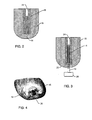
- an amputated patient limb 18 such as the upper leg in the case of a transfemoral amputee includes a portion of a long patient bone 20 such as the femur which, prior to amputation, anatomically supports a range of loads encountered during normal ambulatory movements.
- the femur 20 is surgically severed, and upon healing is covered by soft stump tissue 22 including skin and the like.
- FIG. 3 shows the bone anchored mounting post 14 in the form of an elongated tube or rod constructed typically from a high strength and biocompatible metal or the like and adapted for secure affixation within the intramedullary canal 24 of the long patient bone 20.
- mounting post affixation can be obtained by a threaded post construction (not shown) adapted for thread-in placement into the medullary canal 24, or by alternative affixation means (also not shown) such as press-fitting, and/or by the provision of a bone ingrowth surface or surfaces on the mounting post 14.
- the fixator structure 16 comprises an elongated post or pin carried by or formed integrally with the implanted bone anchored mounting post 14, and protrudes therefrom through the overlying soft stump tissue 22 to an externally positioned lower or distal end.
- the lower or distal end of the fixator structure 16 includes or carries a mounting element 26 such as the illustrative radially enlarged mounting flange for releasible connection to the prosthesis 12. This releasible connection is provided by the attachment system 10 of the present invention.
- FIG. 1 shows the attachment system 10 in accordance with one preferred form of the invention.
- the system 10 including the safety release mechanism comprises a first component in the form of an upper socket member 28 for spring-loaded clamp-on and substantially snap-fit releasible reception and retention of the mounting flange 26 on the fixator structure 16.
- This upper socket member 28 comprises a generally cup-shaped structure having a sturdy and rigid base plate 30 in combination with an upstanding sturdy and rigid peripheral wall 32 which cooperates with the base plate 30 to define an upwardly open, generally cup-shaped receptacle.
- a plurality of at least two jaw elements 34 are pivotally mounted at or near an upper margin of the peripheral wall 32 in a radially inwardly projecting orientation. Springs 36 urge these jaw elements 34 toward a normal position pivoted downwardly relative to the peripheral wall 32.
- the spring-loaded jaw elements 36 cooperate with the base wall 30 and associated peripheral wall 32 to define a pocket 38 ( FIG. 8 ) having a size and shape for clamped, substantially snap-fit reception of the mounting flange 26 on the fixator structure 16.
- the downwardly loaded jaw elements 36 springably support and retain the mating flange 26 in an essentially fixed position relative to the socket member 28, throughout a normal range of mechanical loads.
- the spring-loaded jaw elements 36 are designed to accommodate movement of the mounting flange 26 relative to the socket member 28 when a force overload condition occurs.
- a relatively short tension member or tension band 40 (shown in FIG. 5 ) is suitably connected to the underside of the socket member base plate 30, and extends downwardly therefrom for suitable connection to an upper face of a lower base link 42.
- This lower base link 42 comprises a second component and is shown connected to the prosthesis 12 which may include one or more mechanical links secured to each other by appropriate fasteners 13 or the like.
- a plurality of radially outwardly and downwardly open detent seats 44 are defined between a sawtooth array 46 protruding downwardly from the underside of the base plate 30.
- a corresponding plurality of radially projecting detent pins 48 are carried by or formed on the lower base link 42 for respective seated engagement within the detent seats 44 of the sawtooth array 46.
- the tension band 40 (which may be formed from a strong and longitudinally resilient material such as metals, plastics, wood and composites) draws the lower base link 42 upwardly for secure and stable, substantially rigid seated engagement of the detent pins 48 within the sawtooth detent seats 44.
- the tension band 40 accommodates relative movement between the upper socket member 28 and the lower base link 42 when a force overload condition occurs.
- FIGS. 5-8 illustrate safety release operation of the attachment system 10 in response to a bending force overload condition, wherein a bending force illustrated by arrow 50 is encountered with a magnitude exceeding a predetermined maximum limit.
- the tension band 40 in initially stretched ( FIG. 5 ) to accommodate pivoting motion of the lower base link 42 away from the sawtooth array 46 at the underside of the upper socket member 28.
- the tension band 40 springably or elastically permits a limited amount of relative movement between the socket member 28 and base link 42 to protect the prosthetic components including the attachment interface of the implanted mounting post 14 with patient bone 20 against risk of fracture failure.
- the spring-loaded jaw elements 36 Upon encountering a larger magnitude bending force overload, as viewed in FIG. 6 , the spring-loaded jaw elements 36 are designed to displace. That is, the mounting flange 26 at the lower end of the fixator structure 16 bears against the underside surfaces of the jaw elements 36 and forces them to pivot upwardly in a manner permitting limited relative movement therebetween. If the bending force overload condition is severe enough, the jaw elements 36 will continue to pivot upwardly as viewed in FlG. 7 to accommodate complete release or separation of the socket member 28 from the mounting flange 26 ( FIG. 8 ). Such socket member separation is, of course, accompanied by complete release or separation of the prosthesis 12 from the amputated limb 18.
- FIG. 9 shows response of the attachment system 10 to a tensile force overload acting in the direction of arrow 52.
- the tension band 40 elongates to accommodate relative motion between the upper socket member 28 and the lower base link 42.
- further downward force on the tension band 40 will eventually exceed the retention force applied to the fixture structure mounting flange 26 by the spring-loaded jaw elements 36, resulting in separation and release of the mounting flange 26 from the socket member 28 as depicted generally in FIG. 8 .
- such component separation beneficially protects the prosthesis components and the patient bone 20 against fracture failure.
- FIG. 10 illustrates response of the attachment system 10 to a torsion force overload condition represented by arrow 54.
- the detent pins 48 on the lower base link 42 ride downwardly within the individual detent seats 44 defined by the sawtooth array 46, for accommodating rotation of the lower base link 42 relative to the sawtooth array in the direction of the applied torque.
- the tension band 40 stretch-elongates sufficiently to accommodate this relative rotation, and then draws the detent pins 48 back upwardly into adjacent seats 44 defined by the sawtooth array.
- the sawtooth array 46 cooperates with the detent pins 48 and the tension band 40 to provide a spring-loaded torsion clutch that accommodates relative rotation in either direction upon encountering a torsion force overload.
- forces applied to the prosthesis 12 and the related attachment system 10 typically comprise a combination of bending, tensile, and/or torsion forces.
- the attachment system 10 of the present invention responds cooperatively to these applied forces to provide a sturdy and essentially rigid interconnection between the prosthesis 12 and patient bone 20, provided that these forces do not exceed a predetermined safe design limit in any direction. If and when the applied forces do exceed such predetermined safe design limit in any or in a combination of directions, the attachment system 10 responds to permit an appropriate degree of relative movement between components sufficient to prevent fracture failures. If the applied force overload is sufficiently high, the permitted relative movement involves separation of the prosthesis from the fixator structure 16 of the bone anchored mounting post 14.
- FIGS. 11-25 depict an alternative preferred form of the invention, wherein a modified releasible attachment unit 110 is provided for connection between an external fixator structure 116 ( FIGS. 12-13 ) formed on or carried by a bone anchored mounting post (not shown) or the like and an exoskeletal prosthesis 112 such as a prosthetic limb.
- This modified releasible attachment unit 110 includes a first component in the form of an upwardly projecting mounting stud 60 having a non-circular cross sectional shape such as the illustrative square cross section for quick and easy attachment to the fixator structure 116 in any suitable manner, as by means of one or more set screws (not shown).
- the attachment unit 110 further includes a second component in the form of a downwardly projecting mounting stud 62 which also has a non-circular cross sectional shape such as the illustrative square shape for quick and easy attachment in a secure and stable manner to the prosthesis 112, as by means of one or more set screws (also not shown).
- a second component in the form of a downwardly projecting mounting stud 62 which also has a non-circular cross sectional shape such as the illustrative square shape for quick and easy attachment in a secure and stable manner to the prosthesis 112, as by means of one or more set screws (also not shown).
- the releasible attachment unit 110 normally provides a rigid, substantially motion-free interface connection between the fixator structure 116 and the prosthesis 112 for normal patient movements, such as normal walking movements in the case of a prosthetic leg.
- the attachment unit 110 upon encountering a force overload condition attributable, for example, to an excessive bending force or an excessive torsion force, the attachment unit 110 is designed to release quickly and substantially completely to prevent transmission of said excessive force via the fixator structure 116 to the patient bone.
- the releasible attachment unit 110 comprises a safety release mechanism of alternative design for safeguarding against highly undesirable fracture failures.
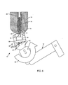
- the modified releasible attachment unit 110 comprises an upper bending force clutch 64 for adjustably responding to a bending force overload condition, and a lower torsion force clutch 66 for adjustably responding to a torsion force overload condition.
- the upper clutch 64 includes a relatively large ball member 68 having the upwardly projecting mounting stud 60 carried thereon as by integral formation therewith.
- This ball member 68 is coupled by means of a universal joint linkage 70 with the lower torsion force clutch comprising an underlying torque cartridge 72 including spring-loaded detent balls 74.
- the ball member 68 and the torque cartridge 72 are carried within a lower, generally cup-shaped unit housing 76.
- the downwardly projecting mounting stud 62 is carried on the underside of this housing 76 as by integral formation thereon.
- the ball member68 comprises a relatively large part-spherical or ball-shaped component of generally hemispherical configuration.
- the ball member 68 has a diametric size for slide-fit reception into the upwardly open unit housing 76, as viewed best in FIGS. 21-25 .
- the upper mounting stud 60 projects upwardly from the ball member 68.
- the ball member 68 is oriented within the unit housing 76 so that the upper mounting stud 60 projects generally coaxially with respect to the unit housing 76 ( FIGS. 21-22 and 25 ), for suitable connection of the stud 60 to the fixator structure 116 ( FIGS. 12-13 ) as previously described.
- a peripheral groove 78 is formed in the ball member 68 generally near a lower margin thereof, for spring-loaded partial reception of a circumferential array of clutch balls 80 carried within a respective plurality of radially outwardly open ports 81 formed in the housing 76 near the open upper end thereof.
- Each clutch ball 80 is adapted for radially inward biasing with a selected spring force for partial reception into the ball member groove 78, for purposes of releasibly locking the ball member 68 in the upright normal operating position.
- the spring locking force is adjustably selectable for custom setting of a release force or release point in response to a bending force exceeding a predetermined selected threshold value.
- the clutch balls 80 retract radially outwardly from the ball member groove 78 sufficiently to permit ball rotation or displacement from the normally locked operating position to an unlocked angular position as viewed in FIGS. 23-24 .
- the spring locking/release force is adjustably set by means of an inner adjustment ring 82 rotatably carried within a generally annular cover 84 fastened onto the upper end of the unit housing 76 as by means of a plurality of short screws 86 or the like.
- This annular cover 84 has a radially in-turned upper flange 88 which overlies and engages an annular shoulder 90 on the inner adjustment ring 82 to retain said ring 82 in a position with an inner diameter surface 92 thereof pressed against the part-spherical outer surface of the ball member 68.
- the inner adjustment ring 82 has an externally threaded segment 94 engaged with an internally threaded segment 96 of an outer adjustment ring 98.
- This internally threaded segment 96 of the outer adjustment ring 98 merges with a tapered-edge bearing seat 100 positioned for bearing against an outboard spacer 102 of a clutch spring assembly including a disk spring 104 or the like interposed between the outboard spacer 102 and an inboard spaces 106 engaged in turn with an associated one of the clutch balls 80.
- Rotation of the inner adjustment ring 82 causes upward or downward translation of the outer adjustment ring 98, in accordance with the direction of rotational displacement.
- the outer adjustment ring 98 has as least one axially or vertically elongated slot 97 formed therein for slide-guided reception of an associated set screw 99 on the cover 84 to limit the outer adjustment ring 98 to axial or up/down displacement in response to rotation of the inner adjustment ring 82.
- the ball member 68 is returnable to the upright normal operating position in a manner that does not require application of substantial force or effort.
- the inner adjustment ring 82 can be rotationally displaced to retract the outer adjustment ring 98 upwardly and thereby retract the tapered-edge bearing seat 100 upwardly relative to the clutch spring assemblies. This results in a substantial relieving of the spring forces urging the clutch balls 80 in a radially inwardly direction, and thereby permits relatively quick and easy return of the ball member 68 to the upright normal operating position.
- the inner adjustment ring 82 can be reverse-rotated in a manner increasing the bending force release point to the desired higher level, as previously described.
- the universal joint linkage 70 interconnects the ball member 68 with the lower torsion force clutch 66 mounted within a lower end of the cup-shaped unit housing 76.
- the U-joint linkage comprises an upper drive member 160 of non-circular cross sectional shape, such as a square-drive key or the like, seated within a matingly shaped socket 162 formed within a hollow underside of the ball member 68.
- the U-joint linkage 70 additionally includes a lower drive member 164 which is also formed with a non-circular shape, such as a square-drive key or the like, seated within a matingly shaped socket 166 formed on the upper side of a torque member or torque plate 168.
- U-joint linkage 70 These upper and lower drive members 160 and 164 of the U-joint linkage 70 are rotatably interconnected as by means of a pair of pivotally joined link components conventionally provided in a so-called universal joint. Accordingly, further description of U-joint construction details are not included herein, such details being known to persons skilled in the art.
- One preferred and exemplary U-joint linkage is available from Lovejoy, Inc., of Downers Grove, IL, under the product designation D-2 Solid U-Joint.
- the torque plate 168 comprises a portion of the torque cartridge 72, and has a generally disk-shaped profile sized for slide-fit reception into a cylindrical lower region of the cup-shaped unit housing 76, preferably within an annular torque or spacer ring 170 which is slidably seated in turn within the housing 76 and locked against rotation therein as by radially extending set pins 172 ( FIG. 22 ).
- the torque plate 168 is diametrically sized for relatively free rotation within the torque spacer ring 170, and includes an axially downwardly projecting tab 174 extending into a part-annular channel 176 formed in a base wall 178 of the unit housing 76. As shown best in FIG. 18 , this part-annular channel 176 extends on a common radius through an arcuate length dimension of less than 360°, such as an arcuate length on the order of about 340-350°.
- a diametrically extending bore 180 is formed in the body of the torque plate 168.
- This bore 180 is sized and shaped to receive and support a spring unit 182 including, e.g., a set of disk springs 184 sandwiched between a pair of spacers 186.
- the spacers 186 bear in turn against a pair of detent balls 74 to urge those balls 74 radially outwardly beyond the perimeter of the torque plate 168 with a predetermined force setting.
- the detent balls 74 are urged radially outwardly into a matingly shaped and diametrically aligned pairof shallow detent seats 190 formed in the inner diameter surface of the torque spacer ring 170.
- the spring unit 182 normally engages and locks with the torque spacer ring 170 for releasibly maintaining the torque plate 168 in a predetermined rotational position relative to the torque spacer ring 170 and the associated unit housing 76.
- the tab 174 on the torque plate 168 is positioned within the underlying channel 176 generally mid-way between the opposed channel ends.
- the detent balls 74 retract against the springs 184 sufficiently to permit relative rotation between the torque plate 168 and the torque spacer ring 170 within the unit housing 76.
- Such relative rotation corresponds with safety release of the attachment unit 110 to prevent undesired fracture failure.
- the prosthesis 112 is thus permitted to rotate with the housing 76, relative to the torque plate 168 and ball member 68 coupled thereto wherein the ball member 68 is coupled in turn to the patient bone interface.
- the tab 174 accommodates such rotation through an angular increment of nearly but less than 180°, such as an increment of about 160°.
- Such rotational increment is normally sufficient to relieve the torsion force overload, and also precludes re-engagement of the detent balls 74 with the opposed detent seats 190. Accordingly, with the detent balls 74 disengaged from the detent seats 190, the unit 110 can be returned quickly and easily to the desired normal operating position by merely back-rotating the prosthesis 112 and/or housing 76 until the detent balls 74 re-engage in a snap-fit manner with the associated detent seats 190.
- the attachment unit 110 provides a safety release mechanism for securely interconnecting the prosthesis 112 with the associated bone-supported fixator structure 116 in a substantially motion-free secure and stable manner during normal operating conditions.
- the attachment unit 110 upon encountering a bending force overload condition, or a torsion force overload condition, or a combination thereof, the attachment unit 110 provides the requisite safety release mechanism for quickly and substantially completely de-coupling in a manner to safeguard the bone-supported interface against fracture failures.
- the attachment unit 110 can be returned quickly and easily to a normal operation position for resumed patient use.
Landscapes
- Health & Medical Sciences (AREA)
- Cardiology (AREA)
- Oral & Maxillofacial Surgery (AREA)
- Transplantation (AREA)
- Engineering & Computer Science (AREA)
- Biomedical Technology (AREA)
- Heart & Thoracic Surgery (AREA)
- Vascular Medicine (AREA)
- Life Sciences & Earth Sciences (AREA)
- Animal Behavior & Ethology (AREA)
- General Health & Medical Sciences (AREA)
- Public Health (AREA)
- Veterinary Medicine (AREA)
- Orthopedic Medicine & Surgery (AREA)
- Prostheses (AREA)
Abstract
Description
- This invention relates generally to improvements in external or exoskeletal prosthetic devices and systems of the type utilizing an implanted, bone anchored mounting post having or carrying an externally protruding or externally exposed fixator structure for removable attachment to a prosthesis such as a prosthetic limb or the like. More particularly, this invention relates to an improved attachment system for coupling the external fixator structure to the prosthesis, wherein the attachment system includes a safety release mechanism adapted to release in response to an excess mechanical load applied to the prosthesis.
- Sockettype prosthetic limbs such as prosthetic arm and leg structures for use by amputees are generally well known in the art, wherein a prosthesis is constructed with an open-ended and typically padded socket structure for receiving and supporting the post-surgical stump of an amputated limb. By way of example, a socket type prosthetic leg includes such open-ended socket structure at an upper end thereof for receiving and supporting the post-surgical upper leg of a transfemoral amputee. Various straps and/or other fasteners are provided for securing the prosthetic leg to the amputated limb to accommodate walking mobility at least on a limited basis. Such prosthetic limbs can be an important factor in both physical and mental rehabilitation of an amputee.
- However, socket type prosthetic limbs are associated with a number of recognized limitations and disadvantages. In particular, the socket style prosthesis inherently couples mechanical loads associated with normal ambulatory activity through a soft tissue interface defined by the soft tissue covering the end or stump of the amputated limb, but wherein this soft tissue interface is structurally unsuited for this purpose. While many different arrangements and configurations for the requisite straps and other fasteners have been proposed for improved transmission and distribution of these mechanical loads to bone structures to achieve an improved secure and stable prosthesis attachment, to correspondingly accommodate a more natural ambulatory movement, such arrangements have achieved only limited success. In addition, compressive loading of the soft stump tissue interface often results in blisters, sores, chafing and other undesirable skin irritation problems which have been addressed primarily by adding soft padding material within the socket structure. But such soft padding material undesirably increases the extent of the soft or non-rigid interface between the amputated limb and prosthesis, all in a manner that is incompatible with an optimally secure and stable prosthesis connection. As a result, particularly in the case of a prosthetic leg, traditional socket style connection structures and methods have generally failed to accommodate a normal walking motion.
- In recent years, improved external or exoskeletal prosthetic devices have been proposed, wherein the external prosthesis is structurally linked by means of a bone anchored mounting system directly to patient bone. In such devices, a rigid mounting post is surgically implanted and attached securely to patient bone as by means of osseointegration or the like. This implanted bone anchored mounting post extends from the bone attachment site and includes or is attached to a fixator pin or post structure that protrudes through the overlying soft stump tissue at the end of the amputated limb. Thus, one end of the fixator structure is externally exposed for secure and direct mechanical attachment to a prosthetic limb or the like by means of a rigid linkage.
- In such bone anchored mounting systems, mechanical loads on the prosthetic limb during ambulation are thus transmitted by the rigid linkage and through the external fixator structure and implanted mounting post directly to patient bone. As a result, conventional and undesirable mechanical loading of the soft tissue interface is avoided, and substantially improved and/or substantially normal patient movements are accommodated. In addition, the requirement for compressive loading of the soft tissue at the end of the amputated limb is significantly reduced, to correspondingly reduce incidence of blisters and other associated skin irritation problems. Moreover, by mechanically linking and supporting the prosthesis directly from patient bone, amputees have reported a significant increase in perception of the prosthesis as an actual and natural body part-a highly desirable factor referred to as "osseoperception".
- Although use of a bone anchored mounting system offers potentially dramatic improvements in secure and stable prosthetic limb attachment, and corresponding improvements in amputee lifestyle, major complications can arise when the prosthetic structure encounters a mechanical load that exceeds normal design parameters. More particularly, in the event of a tensile, bending, or torsion load exceeding structural design limitations, fracture-failure can occur. Breakage of prosthesis structures such as the implanted bone anchored mounting post often requires repair by surgery. Breakage of the patient bone at or near the interface with the implanted mounting post also requires surgical repair, and reseating or replacement of the implanted mounting post may not be possible. Both of these failure modes represent traumatic and highly undesirable complications.
- There exists, therefore, a significant need for further improvements in and to external or exoskeletal prosthetic devices of the type utilizing a bone anchored mounting post, wherein an improved attachment system couples the prosthetic device to an externally protruding fixator structure in a manner accommodating substantially normal patient movement and a corresponding range of normal mechanical loads, but wherein the improved attachment system includes a safety release mechanism adapted to release in response to an excess mechanical load thereby preventing undesirable fracture failures. The present invention fulfills these needs and provides further related advantages.
- In accordance with the invention, an improved releasible attachment system is provided for use in combination with a bone anchored post and related external prosthesis such as a prosthetic limb or the like adapted for connection thereto. The bone anchored mounting post comprises an implant component adapted for secure and stable affixation to patient bone. This bone anchored mounting post carries or is connected to a fixator structure such as an elongated pin which protrudes through soft skin tissue and the like covering the end or stump of an amputated limb, and is adapted for secure and stable attachment to the external or exoskeletal prosthesis. The improved attachment system incorporates a safety release mechanism designed to accommodate substantially normal patient movement and a corresponding range of substantially normal mechanical loads. However, in the event of an excess mechanical load applied to the prosthetic structures and/or to the implant interface of the mounting post with patient bone, the safety release mechanism is designed to release or break away thereby preventing undesirable fracture failure modes. The safety release mechanism is designed for response to excessive bending, tensile, and/or torsion load.
- In a preferred form, the releasible attachment system is interposed between the prosthesis and the fixator structure, and is adapted for mechanical connection with a radially enlarged mounting flange on the fixator structure. The safety release mechanism includes an upper socket member lined by a plurality of spring-loaded jaw elements for releasible clamp-on, substantially snap-fit engagement with the fixator structure mounting flange. The socket member is coupled by a resilient tension band to a lower release clutch including a plurality of downwardly presented, radially open detent seats having a sawtooth geometry or the like for respectively receiving a plurality of radially projecting detent pins. The tension band normally draws and retains the detent pins securely within the detent seats.
- Upon encountering a bending force exceeding a predetermined limit, the tension band accommodates relative movement between the upper socket member and the lower release clutch, while the spring-loaded jaw elements accommodate relative movement between the socket member and the fixator structure mounting flange. When the bending force exceeds a predetermined limit, the jaw elements will accommodate separation of the socket member from the fixator structure. Similarly, upon encountering a tensile force load exceeding a predetermined limit, the tensile band will elongate and/or the spring-loaded jaw elements will displace to accommodate similar relative motions between components of the attachment system. Upon encountering a torsion force load exceeding a predetermined limit, the tensile band will elongate sufficiently to accommodate relative rotational displacement between the detent pins and the detent seats.
- In an alternative preferred form of the invention, the attachment system or unit comprises a bending force clutch for adjustably responding to a bending force overload condition, and a torsion force clutch for adjustably responding to a torsion force overload condition. The bending force clutch comprises a relatively large ball-shaped member having a peripheral groove for normally seated reception of an array of spring-loaded clutch balls. This ball member is coupled by means of a universal joint linkage with the torsion force clutch comprising a torque cartridge inducing spring-loaded detent balls carried within a generally cup-shaped unit housing. The ball member and the unit housing are adapted for connection between the bone anchored fixator structure and the prosthesis. The ball member is designed for angular movement relative to the housing in response to a bending force overload condition, whereas the torque cartridge is designed for rotational movement relative to the housing in response to a torsion force overload condition.
- Other features and advantages of the present invention will become apparent from the following more detailed description, taken in connection with the accompanying drawing which illustrate, by way of example, the principals of the present invention.
- The accompanying drawings illustrate the invention. In such drawings:
-
FIGURE 1 is a somewhat schematic diagram showing the releasible attachment system of the present invention in combination with a bone anchored prosthesis mounting post for use in releasible external attachment to an exoskeletal prosthesis; -
FIGURE 2 is a somewhat schematic diagram illustrating an amputated upper leg portion of a transfemoral amputee, prior to implanted installation of a bone anchored mounting post; -
FIGURE 3 is a somewhat schematic diagram similar toFIG. 2 , but showing the amputated upper leg portion following implantation of the bone anchored mounting post; -
FIGURE 4 is a fragmented perspective view showing the lower or stump end of the amputated upper leg portion, and illustrating a fixator structure protruding externally from the amputated limb; -
FIGURE 5 is a somewhat schematic diagram similar toFIG. 1 , but depicting initial release and displacement of the attachment system in response to a bending force overload condition; -
FIGURES 6 through 8 are diagrams similar toFIG. 5 , and showing successively further release and displacement of the attachment system in response to a bending force overload condition; -
FIGURE 9 is another schematic diagram similar toFIGS. 1 and5-8 , illustrating initial release and displacement of the attachment system in response to a tensile force overload condition; -
FIGURE 10 is a somewhat schematic diagram similar toFIGS. 1 and5-9 , and showing initial release and displacement of the attachment system in response to a torsion force overload condition; -
FIGURE 11 is a perspective view showing the top, front and left sides of a releasible attachment unit constructed in accordance with one alternative preferred form of the invention; -
FIGURE 12 is a front elevation view of the releasible attachment unit ofFIG. 11 ; -
FIGURE 13 is a left side elevation view of the releasible attachment unit ofFIG. 11 ; -
FIGURE 14 is an exploded top perspective view of the releasible attachment unit ofFIG. 11 ; -
FIGURE 15 is an exploded bottom perspective view of the releasible attachment unit ofFIG. 11 ; -
FIGURE 16 is an exploded front view of the releasible attachment unit ofFIG. 11 ; -
FIGURE 17 is an exploded saggital or medial-lateral sectional view of the releasible attachment unit shown inFIG. 16 ; -
FIGURE 18 is an enlarged top plan view of a cup-shaped housing forming a portion of the releasible attachment unit, taken generally on the line 18-18 ofFIG. 17 ; -
FIGURE 19 is an exploded left side elevation view of the releasible attachment unit ofFIG. 11 ; -
FIGURE 20 is an exploded anterior-posterior sectional view of the releasible attachment unit shown inFIG. 19 ; -
FIGURE 21 is an enlarged saggital or medial-lateral sectional view of the assembled releasible attachment unit shown inFIG. 17 ; -
FIGURE 22 is an enlarged anterior-posterior sectional view of the assembled releasible attachment unit shown inFIG. 20 ; -
FIGURE 23 is an enlarged anterior-posterior sectional view similar toFIG. 22 , but showing a ball member displaced to a released position in response to a force overload condition; -
FIGURE 24 is an enlarged anterior-posterior sectional view similar toFIG. 23 , but illustrating threaded retraction of an inner adjustment ring to relieve spring-loaded retention forces acting on the ball member, thereby facilitating return movement of the ball member to a normal operating position; and -
FIGURE 25 is an enlarged anterior-posterior sectional view similar toFIG. 24 , and depicting return displacement of the ball member to the normal operating position. - As shown in the exemplary drawings, an attachment system referred to generally by the
reference numeral 10 inFIGURES 1 and5-10 is provided for releasibly connecting an external orexoskeletal prosthesis 12 in a bone anchored mounting system of the type having an implanted bone anchored mountingpost 14. Theattachment system 10 is designed for secure and stable attachment of the bone anchored mountingpost 14 to theexternal prosthesis 12, such as a prosthetic limb or the like for an amputee. In accordance with the invention, theattachment system 10 includes a safety release means or mechanism which provides a substantially rigid and direct-coupled attachment of theprosthesis 12 to an externally protrudingfixator structure 16 formed on or carried by the implanted mountingpost 14, to accommodate a substantially normal range of force loads encountered during substantially normal movement and/or use of theprosthesis 12. However, the safety release mechanism is also designed for displacement and ultimately for breakaway separation in response to an applied force load exceeding a predetermined design limit, thereby safeguarding the prosthesis and the bone-mounting post attachment interface against undesired fracture failure. - The
releasible attachment system 10 of the present invention is particularly designed for use with external or exoskeletal prosthetic fixation or mounting systems of the type having the internal, implanted bone anchored mountingpost 14 which is surgically attached to and securely supported by patient bone, as by means of osseointegration or the like. For example, with reference toFIGS. 2-4 , an amputatedpatient limb 18 such as the upper leg in the case of a transfemoral amputee includes a portion of along patient bone 20 such as the femur which, prior to amputation, anatomically supports a range of loads encountered during normal ambulatory movements. When amputated, as viewed inFIG. 2 , thefemur 20 is surgically severed, and upon healing is covered bysoft stump tissue 22 including skin and the like. -
FIG. 3 shows the bone anchored mountingpost 14 in the form of an elongated tube or rod constructed typically from a high strength and biocompatible metal or the like and adapted for secure affixation within theintramedullary canal 24 of thelong patient bone 20. In this regard, mounting post affixation can be obtained by a threaded post construction (not shown) adapted for thread-in placement into themedullary canal 24, or by alternative affixation means (also not shown) such as press-fitting, and/or by the provision of a bone ingrowth surface or surfaces on the mountingpost 14. Thefixator structure 16 comprises an elongated post or pin carried by or formed integrally with the implanted bone anchored mountingpost 14, and protrudes therefrom through the overlyingsoft stump tissue 22 to an externally positioned lower or distal end. As shown inFIGS. 3-4 , the lower or distal end of thefixator structure 16 includes or carries a mountingelement 26 such as the illustrative radially enlarged mounting flange for releasible connection to theprosthesis 12. This releasible connection is provided by theattachment system 10 of the present invention. -
FIG. 1 shows theattachment system 10 in accordance with one preferred form of the invention. As shown, thesystem 10 including the safety release mechanism comprises a first component in the form of anupper socket member 28 for spring-loaded clamp-on and substantially snap-fit releasible reception and retention of the mountingflange 26 on thefixator structure 16. Thisupper socket member 28 comprises a generally cup-shaped structure having a sturdy andrigid base plate 30 in combination with an upstanding sturdy and rigidperipheral wall 32 which cooperates with thebase plate 30 to define an upwardly open, generally cup-shaped receptacle. A plurality of at least twojaw elements 34 are pivotally mounted at or near an upper margin of theperipheral wall 32 in a radially inwardly projecting orientation.Springs 36 urge thesejaw elements 34 toward a normal position pivoted downwardly relative to theperipheral wall 32. - With this construction, the spring-loaded
jaw elements 36 cooperate with thebase wall 30 and associatedperipheral wall 32 to define a pocket 38 (FIG. 8 ) having a size and shape for clamped, substantially snap-fit reception of the mountingflange 26 on thefixator structure 16. The downwardly loadedjaw elements 36 springably support and retain themating flange 26 in an essentially fixed position relative to thesocket member 28, throughout a normal range of mechanical loads. However, as will be described in more detail, the spring-loadedjaw elements 36 are designed to accommodate movement of the mountingflange 26 relative to thesocket member 28 when a force overload condition occurs. - A relatively short tension member or tension band 40 (shown in
FIG. 5 ) is suitably connected to the underside of the socketmember base plate 30, and extends downwardly therefrom for suitable connection to an upper face of alower base link 42. Thislower base link 42 comprises a second component and is shown connected to theprosthesis 12 which may include one or more mechanical links secured to each other byappropriate fasteners 13 or the like. A plurality of radially outwardly and downwardlyopen detent seats 44 are defined between asawtooth array 46 protruding downwardly from the underside of thebase plate 30. A corresponding plurality of radially projecting detent pins 48 are carried by or formed on thelower base link 42 for respective seated engagement within the detent seats 44 of thesawtooth array 46. In a normal position, the tension band 40 (which may be formed from a strong and longitudinally resilient material such as metals, plastics, wood and composites) draws thelower base link 42 upwardly for secure and stable, substantially rigid seated engagement of the detent pins 48 within the sawtooth detent seats 44. However, and as will be described herein in more detail, thetension band 40 accommodates relative movement between theupper socket member 28 and thelower base link 42 when a force overload condition occurs. -
FIGS. 5-8 illustrate safety release operation of theattachment system 10 in response to a bending force overload condition, wherein a bending force illustrated byarrow 50 is encountered with a magnitude exceeding a predetermined maximum limit. Upon such bending force overload, thetension band 40 in initially stretched (FIG. 5 ) to accommodate pivoting motion of thelower base link 42 away from thesawtooth array 46 at the underside of theupper socket member 28. Accordingly, in the presence of a relatively minor bending force overload, thetension band 40 springably or elastically permits a limited amount of relative movement between thesocket member 28 andbase link 42 to protect the prosthetic components including the attachment interface of the implanted mountingpost 14 withpatient bone 20 against risk of fracture failure. - Upon encountering a larger magnitude bending force overload, as viewed in
FIG. 6 , the spring-loadedjaw elements 36 are designed to displace. That is, the mountingflange 26 at the lower end of thefixator structure 16 bears against the underside surfaces of thejaw elements 36 and forces them to pivot upwardly in a manner permitting limited relative movement therebetween. If the bending force overload condition is severe enough, thejaw elements 36 will continue to pivot upwardly as viewed in FlG. 7 to accommodate complete release or separation of thesocket member 28 from the mounting flange 26 (FIG. 8 ). Such socket member separation is, of course, accompanied by complete release or separation of theprosthesis 12 from the amputatedlimb 18. While such prosthesis separation renders the prosthesis temporarily ineffective (until re-attached to the fixator structure 16) and may cause the patient to fall, e.g., when the prosthesis comprises an artificial leg, the prosthetic components and thepatient bone 20 are protected against fracture failure. -
FIG. 9 shows response of theattachment system 10 to a tensile force overload acting in the direction ofarrow 52. In particular, upon encountering a tension force overload, thetension band 40 elongates to accommodate relative motion between theupper socket member 28 and thelower base link 42. In the event of a tension overload of substantial degree, further downward force on thetension band 40 will eventually exceed the retention force applied to the fixturestructure mounting flange 26 by the spring-loadedjaw elements 36, resulting in separation and release of the mountingflange 26 from thesocket member 28 as depicted generally inFIG. 8 . Once again, such component separation beneficially protects the prosthesis components and thepatient bone 20 against fracture failure. -
FIG. 10 illustrates response of theattachment system 10 to a torsion force overload condition represented byarrow 54. As shown, in the event of torsion force overload, the detent pins 48 on thelower base link 42 ride downwardly within theindividual detent seats 44 defined by thesawtooth array 46, for accommodating rotation of thelower base link 42 relative to the sawtooth array in the direction of the applied torque. Thetension band 40 stretch-elongates sufficiently to accommodate this relative rotation, and then draws the detent pins 48 back upwardly intoadjacent seats 44 defined by the sawtooth array. Accordingly, thesawtooth array 46 cooperates with the detent pins 48 and thetension band 40 to provide a spring-loaded torsion clutch that accommodates relative rotation in either direction upon encountering a torsion force overload. - In actual use, forces applied to the
prosthesis 12 and therelated attachment system 10 typically comprise a combination of bending, tensile, and/or torsion forces. Theattachment system 10 of the present invention responds cooperatively to these applied forces to provide a sturdy and essentially rigid interconnection between theprosthesis 12 andpatient bone 20, provided that these forces do not exceed a predetermined safe design limit in any direction. If and when the applied forces do exceed such predetermined safe design limit in any or in a combination of directions, theattachment system 10 responds to permit an appropriate degree of relative movement between components sufficient to prevent fracture failures. If the applied force overload is sufficiently high, the permitted relative movement involves separation of the prosthesis from thefixator structure 16 of the bone anchored mountingpost 14. -
FIGS. 11-25 depict an alternative preferred form of the invention, wherein a modifiedreleasible attachment unit 110 is provided for connection between an external fixator structure 116 (FIGS. 12-13 ) formed on or carried by a bone anchored mounting post (not shown) or the like and anexoskeletal prosthesis 112 such as a prosthetic limb. This modifiedreleasible attachment unit 110 includes a first component in the form of an upwardly projecting mountingstud 60 having a non-circular cross sectional shape such as the illustrative square cross section for quick and easy attachment to thefixator structure 116 in any suitable manner, as by means of one or more set screws (not shown). Similarly, theattachment unit 110 further includes a second component in the form of a downwardly projecting mountingstud 62 which also has a non-circular cross sectional shape such as the illustrative square shape for quick and easy attachment in a secure and stable manner to theprosthesis 112, as by means of one or more set screws (also not shown). - In operation, the
releasible attachment unit 110 normally provides a rigid, substantially motion-free interface connection between thefixator structure 116 and theprosthesis 112 for normal patient movements, such as normal walking movements in the case of a prosthetic leg. However, upon encountering a force overload condition attributable, for example, to an excessive bending force or an excessive torsion force, theattachment unit 110 is designed to release quickly and substantially completely to prevent transmission of said excessive force via thefixator structure 116 to the patient bone. Accordingly, thereleasible attachment unit 110 comprises a safety release mechanism of alternative design for safeguarding against highly undesirable fracture failures. - In general terms, the modified
releasible attachment unit 110 comprises an upper bending force clutch 64 for adjustably responding to a bending force overload condition, and a lower torsion force clutch 66 for adjustably responding to a torsion force overload condition. Theupper clutch 64 includes a relativelylarge ball member 68 having the upwardly projecting mountingstud 60 carried thereon as by integral formation therewith. Thisball member 68 is coupled by means of a universaljoint linkage 70 with the lower torsion force clutch comprising anunderlying torque cartridge 72 including spring-loadeddetent balls 74. Theball member 68 and thetorque cartridge 72 are carried within a lower, generally cup-shapedunit housing 76. The downwardly projecting mountingstud 62 is carried on the underside of thishousing 76 as by integral formation thereon. - More specifically, the ball member68 comprises a relatively large part-spherical or ball-shaped component of generally hemispherical configuration. The
ball member 68 has a diametric size for slide-fit reception into the upwardlyopen unit housing 76, as viewed best inFIGS. 21-25 . In this position, the upper mountingstud 60 projects upwardly from theball member 68. In a normal operating position, theball member 68 is oriented within theunit housing 76 so that the upper mountingstud 60 projects generally coaxially with respect to the unit housing 76 (FIGS. 21-22 and25 ), for suitable connection of thestud 60 to the fixator structure 116 (FIGS. 12-13 ) as previously described. - A
peripheral groove 78 is formed in theball member 68 generally near a lower margin thereof, for spring-loaded partial reception of a circumferential array ofclutch balls 80 carried within a respective plurality of radially outwardlyopen ports 81 formed in thehousing 76 near the open upper end thereof. Eachclutch ball 80 is adapted for radially inward biasing with a selected spring force for partial reception into theball member groove 78, for purposes of releasibly locking theball member 68 in the upright normal operating position. Importantly, the spring locking force is adjustably selectable for custom setting of a release force or release point in response to a bending force exceeding a predetermined selected threshold value. When theunit 110 is subjected to a bending release force exceeding the selected set point, theclutch balls 80 retract radially outwardly from theball member groove 78 sufficiently to permit ball rotation or displacement from the normally locked operating position to an unlocked angular position as viewed inFIGS. 23-24 . - The spring locking/release force is adjustably set by means of an
inner adjustment ring 82 rotatably carried within a generallyannular cover 84 fastened onto the upper end of theunit housing 76 as by means of a plurality ofshort screws 86 or the like. Thisannular cover 84 has a radially in-turnedupper flange 88 which overlies and engages anannular shoulder 90 on theinner adjustment ring 82 to retain saidring 82 in a position with aninner diameter surface 92 thereof pressed against the part-spherical outer surface of theball member 68. Theinner adjustment ring 82 has an externally threadedsegment 94 engaged with an internally threadedsegment 96 of anouter adjustment ring 98. This internally threadedsegment 96 of theouter adjustment ring 98 merges with a tapered-edge bearing seat 100 positioned for bearing against anoutboard spacer 102 of a clutch spring assembly including adisk spring 104 or the like interposed between theoutboard spacer 102 and aninboard spaces 106 engaged in turn with an associated one of theclutch balls 80. - Rotation of the
inner adjustment ring 82, as by means of engagement of a pair of upwardly open drive ports 108 (FIG. 1 ) by a spanner wrench (not shown) or the like, causes upward or downward translation of theouter adjustment ring 98, in accordance with the direction of rotational displacement. In this regard, theouter adjustment ring 98 has as least one axially or vertically elongatedslot 97 formed therein for slide-guided reception of an associatedset screw 99 on thecover 84 to limit theouter adjustment ring 98 to axial or up/down displacement in response to rotation of theinner adjustment ring 82. Downward displacement of theouter adjustment ring 98 moves the tapered-edge bearing seat 100 thereon into progressively further radially overlying engagement with theoutboard spacers 102 of the clutch spring assemblies, and thereby progressively increases the inward spring force applied to the associatedclutch balls 80. Accordingly, such downward displacement of theouter adjustment ring 98 is accompanied by increased inward spring force applied to theclutch balls 80, and thereby adjustably increases bending release force required to displace theball member 68 from the upright normal operating position. However, as viewed inFIG. 23 , when this adjustably set bending release force limit is reached, as represented by an adjustably set bending force overload condition, theclutch balls 80 retract radially outwardly from the ball membergroove 78 sufficiently to permit rapid shifting of theball member 68 to an angularly oriented release position. - Following such release in response to a bending force overload condition, the
ball member 68 is returnable to the upright normal operating position in a manner that does not require application of substantial force or effort. In this regard, theinner adjustment ring 82 can be rotationally displaced to retract theouter adjustment ring 98 upwardly and thereby retract the tapered-edge bearing seat 100 upwardly relative to the clutch spring assemblies. This results in a substantial relieving of the spring forces urging theclutch balls 80 in a radially inwardly direction, and thereby permits relatively quick and easy return of theball member 68 to the upright normal operating position. When this upright normal position is achieved, theinner adjustment ring 82 can be reverse-rotated in a manner increasing the bending force release point to the desired higher level, as previously described. - The universal
joint linkage 70 interconnects theball member 68 with the lower torsion force clutch 66 mounted within a lower end of the cup-shapedunit housing 76. In this regard, the U-joint linkage comprises anupper drive member 160 of non-circular cross sectional shape, such as a square-drive key or the like, seated within a matingly shapedsocket 162 formed within a hollow underside of theball member 68. TheU-joint linkage 70 additionally includes alower drive member 164 which is also formed with a non-circular shape, such as a square-drive key or the like, seated within a matingly shapedsocket 166 formed on the upper side of a torque member ortorque plate 168. These upper andlower drive members U-joint linkage 70 are rotatably interconnected as by means of a pair of pivotally joined link components conventionally provided in a so-called universal joint. Accordingly, further description of U-joint construction details are not included herein, such details being known to persons skilled in the art. One preferred and exemplary U-joint linkage is available from Lovejoy, Inc., of Downers Grove, IL, under the product designation D-2 Solid U-Joint. - The
torque plate 168 comprises a portion of thetorque cartridge 72, and has a generally disk-shaped profile sized for slide-fit reception into a cylindrical lower region of the cup-shapedunit housing 76, preferably within an annular torque orspacer ring 170 which is slidably seated in turn within thehousing 76 and locked against rotation therein as by radially extending set pins 172 (FIG. 22 ). Thetorque plate 168 is diametrically sized for relatively free rotation within thetorque spacer ring 170, and includes an axially downwardly projectingtab 174 extending into a part-annular channel 176 formed in abase wall 178 of theunit housing 76. As shown best inFIG. 18 , this part-annular channel 176 extends on a common radius through an arcuate length dimension of less than 360°, such as an arcuate length on the order of about 340-350°. - A diametrically extending
bore 180 is formed in the body of thetorque plate 168. This bore 180 is sized and shaped to receive and support aspring unit 182 including, e.g., a set of disk springs 184 sandwiched between a pair ofspacers 186. Thespacers 186 bear in turn against a pair ofdetent balls 74 to urge thoseballs 74 radially outwardly beyond the perimeter of thetorque plate 168 with a predetermined force setting. As shown best inFIG. 21 , thedetent balls 74 are urged radially outwardly into a matingly shaped and diametrically aligned pairofshallow detent seats 190 formed in the inner diameter surface of thetorque spacer ring 170. Accordingly, thespring unit 182 normally engages and locks with thetorque spacer ring 170 for releasibly maintaining thetorque plate 168 in a predetermined rotational position relative to thetorque spacer ring 170 and the associatedunit housing 76. In this normally locked and normal operating position, thetab 174 on thetorque plate 168 is positioned within theunderlying channel 176 generally mid-way between the opposed channel ends. - Upon encountering a torsion force overload condition, wherein the applied torsion force exceeds the spring forces holding the
detent balls 74 within the detent seats 190, thedetent balls 74 retract against thesprings 184 sufficiently to permit relative rotation between thetorque plate 168 and thetorque spacer ring 170 within theunit housing 76. Such relative rotation corresponds with safety release of theattachment unit 110 to prevent undesired fracture failure. Theprosthesis 112 is thus permitted to rotate with thehousing 76, relative to thetorque plate 168 andball member 68 coupled thereto wherein theball member 68 is coupled in turn to the patient bone interface. Importantly, thetab 174 accommodates such rotation through an angular increment of nearly but less than 180°, such as an increment of about 160°. Such rotational increment is normally sufficient to relieve the torsion force overload, and also precludes re-engagement of thedetent balls 74 with the opposed detent seats 190. Accordingly, with thedetent balls 74 disengaged from the detent seats 190, theunit 110 can be returned quickly and easily to the desired normal operating position by merely back-rotating theprosthesis 112 and/orhousing 76 until thedetent balls 74 re-engage in a snap-fit manner with the associated detent seats 190. - Accordingly, the
attachment unit 110 provides a safety release mechanism for securely interconnecting theprosthesis 112 with the associated bone-supportedfixator structure 116 in a substantially motion-free secure and stable manner during normal operating conditions. However, upon encountering a bending force overload condition, or a torsion force overload condition, or a combination thereof, theattachment unit 110 provides the requisite safety release mechanism for quickly and substantially completely de-coupling in a manner to safeguard the bone-supported interface against fracture failures. Following a force overload incident, theattachment unit 110 can be returned quickly and easily to a normal operation position for resumed patient use. - Although various embodiments and alternatives have been described in detail for purposes of illustration, various further modifications may be made without departing from the scope and spirit of the invention. For example, persons skilled in the art will recognize and appreciate that the safety release mechanism as shown and described herein may be constructed in alternative configurations adapted to accommodate relative component movements in response to force overloads applied in different directions. Accordingly, no limitation on the invention is intended by way of the foregoing description and accompanying drawings, except as set forth in the appended claims.
- Additional embodiments forming part of the present disclosure are set out in the paragraphs that follows:
-
Paragraph 1. A releasible attachment system for coupling an exoskeletal prosthesis to a patient limb having a bone anchored mounting post with an external fixator structure, said releasible attachment system comprising: a first component adapted for connection to the fixator structure; a second component adapted for connection to the prosthesis; and a safety release mechanism normally retaining the prosthesis in a rigid substantially motion-free interconnected relation to the fixator structure, said safety release mechanism responding to a force overload condition to permit relative movement between the prosthesis and the fixator structure. - Paragraph 2. The releasible attachment system of
paragraph 1 wherein said force overload condition comprises a bending force exceeding a predetermined magnitude. - Paragraphe 3. The releasible attachment system of
paragraph 1 wherein said force overload condition comprises a tensile force exceeding a predetermined magnitude. - Paragraph 4. The releasible attachment system of
paragraph 1 wherein said force overload condition comprises a torsion force exceeding a predetermined magnitude. - Paragraph 5. The releasible attachment system of
paragraph 1 wherein said safety release mechanism responds to said force overload condition to permit relative movement between said first and second components. - Paragraph 6. The releasible attachment system of
paragraph 1 wherein said safety release mechanism responds to said force overload condition to permit detachment of said first component from the fixator structure. - Paragraph 7. The releasible attachment system of
paragraph 1 wherein said safety release mechanism comprises a bending force clutch responsive to a bending force overload condition to permit relative angular displacement of said second component relative to said first component, and a torsion force clutch responsive to a torsion force overload condition to permit relative rotational displacement of said second component relative to said first component. - Paragraph 8. The releasible attachment system of paragraph 7 further including a universal joint interconnecting said bending and torsion force clutches.
- Paragraph 9. The releasible attachment system of paragraph 7 wherein said bending force clutch comprises a ball member movably mounted within a unit housing, and spring-loaded detent means engageable between said unit housing and said ball member for releasible retaining said ball member in a normal position within said unit housing, said detent means responding to a bending force overload condition to permit angular displacement of said ball member relative to said unit housing.
-
Paragraph 10. The releasible attachment system of paragraph 9 wherein said first component is carried by said ball member, and wherein said second component is carried by said unit housing. - Paragraph 11. The releasible attachment system of paragraph 9 wherein said spring- loaded detent means comprises an array of detent balls, and spring means for urging said detent balls with a selected spring force into engagement with a peripheral groove formed in said ball member.
-
Paragraph 12. The releasible attachment system of paragraph 11 wherein said spring- loaded detent means further comprises adjustment means for adjustably setting a detent spring force applied to said detent balls by said spring means for releasibly retaining said ball member in said normal position. -
Paragraph 13. The releasible attachment system ofparagraph 12 wherein said adjustment means comprises a rotatable adjustment ring carried by said unit housing. -
Paragraph 14. The releasible attachment system of paragraph 7 wherein said torsion force clutch comprises a torque member rotatably mounted within said unit housing, and spring-loaded detent means reacting between said torque member and said unit housing for releasibly retaining said torque member in a normal position fixed against rotation within said unit housing, said detent means responding to a torsion force overload condition to permit rotational displacement of said torque member relative to said unit housing. - Paragraph 15. The releasible attachment system of
paragraph 14 wherein said torsion force clutch further includes means for preventing full revolution rotational displacement of said torque member relative to said unit housing. -
Paragraph 16. The releasible attachment system of paragraph 15 wherein said unit housing has a generally cup-shaped configuration defining a base wall at one end thereof, said means for preventing full revolution displacement of said torque member relative to said unit housing comprising a part-annular channel formed in said base wall and a tab carried by said torque member and protruding into said channel, said tab being generally centered within said channel when said torque member is in said normal position. - Paragraph 17. The releasible attachment system of
paragraph 14 further including a torque ring mounted within said unit housing and fixed against rotation therein, said detent means being engageable between said torque ring and said torque member. -
Paragraph 18. The releasible attachment system ofparagraph 1 wherein first component comprises a socket member including at least one spring-loaded jaw element for releasibly engaging the fixator structure in response to a bending and/ or tensile force overload condition, and wherein said safety release mechanism comprises a torsion clutch coupled between said socket member and the prosthesis. - Paragraph 19. The releasible attachment system of
paragraph 18 wherein said torsion clutch comprises a base plate carried by said socket member, a base link comprising said second component, a tension member coupled between said base plate and said base link, and cooperatively engageable detent means carried by said base plate and said base link. -
Paragraph 20. The releasible attachment system of paragraph 19 wherein said cooperatively engageable detent means comprises a plurality of radially outwardly extending detent pins on one of said base plate and said base link, and a plurality of radially open detent seats defined by the other of said base plate and said base link. - Paragraph 21. A releasible attachment system for coupling an exoskeletal prosthesis to a patient limb having a bone anchored mounting post with an external fixator structure, said releasible attachment system comprising: a first component adapted for connection to the fixator structure; a second component adapted for connection to the prosthesis; and a safety release mechanism normally retaining the prosthesis in a rigid substantially motion-free interconnected relation to the fixator structure, said safety release mechanism responding to a force overload condition to permit relative movement between the prosthesis and the fixator structure; said safety release mechanism comprising a bending force clutch responsive to a bending force overload condition to permit relative angular displacement of said second component relative to said first component, a torsion force clutch responsive to a torsion force overload condition to permit relative rotational displacement of said second component relative to said first component, and a universal joint interconnecting said bending and torsion force clutches.
-
Paragraph 22. The releasible attachment system of paragraph 21 wherein said bending force clutch comprises a ball member movably mounted within a unit housing, and first spring-loaded detent means engageable between said unit housing and said ball member for releasibly retaining said ball member in a normal position within said unit housing, said first detent means responding to a bending force overload condition to permit angular displacement of said ball member relative to said unit housing; and wherein said torsion force clutch comprises a torque member rotatably mounted within said unit housing, and second spring-loaded detent means reacting between said torque member and said unit housing for releasibly retaining said torque member in a normal position fixed against rotation within said unit housing, said second detent means responding to a torsion force overload condition to permit rotational displacement of said torque member relative to said unit housing. - Paragraph 23. The releasible attachment system of paragraph 21 wherein said first component is carried by said ball member, and wherein said second component is carried by said unit housing.
-
Paragraph 24. The releasible attachment system of paragraph 21 wherein said bending force clutch further includes adjustment means for adjustably setting a spring force associated for releasibly retaining said ball member in said normal position. - Paragraph 25. The releasible attachment system of paragraph 21 wherein said torsion force clutch further includes means for preventing full revolution rotational displacement of said torque member relative to said unit housing.
Claims (10)
- A releasable attachment system (10) for coupling an exoskeletal prosthesis (12) to a patient limb having a bone anchored mounting post (14) with an external fixator structure (16), the releasable attachment system comprising:a first component (28) coupled to the fixator structure (16), the first component including
a rigid base plate (30),
an upstanding rigid peripheral wall (32) surrounding the base plate (30),
a plurality of spring-loaded jaw elements (34) pivotally mounted to the peripheral wall (32) and defining a pocket 38 for a clamped, snap-fit reception of the fixator structure (16), and
a sawtooth array (46) protruding downwardly from an underside of the base plate (30) and providing a plurality of detent seats (44);a tension member (40) having a first end and a second end, the first end connected to the rigid base plate (30) of the first component (28); anda second component (42) connected to the second end of the tension member (40) and to the prosthesis (12), the second component including
a plurality of radially projecting detent pins (48) configured for engagement with the detent seats (44) of the sawtooth array (46). - The releasable attachment system of claim 1, wherein the second component is configured to pivot with respect to the first component in response to a bending force overload condition.
- The releasable attachment system of claim 2, wherein the tension member elongates to accommodate angular displacement between the second component and the first component.
- The releasable attachment system of claim 1, wherein the first component is configured to completely release from the fixator structure when the jaw elements pivot upwardly in response to a bending force overload condition.
- The releasable attachment system of claim 1, wherein the second component is configured to completely release from the fixator structure when the retention force of the jaw elements is exceeded in response to a tension force overload condition.
- The releasable attachment system of claim 1, wherein the second component (42) is configured to rotate relative to the first component (28) in response to a torsion force overload condition.
- The releasable attachment system of claim 6, wherein the tension member (40) elongates sufficiently to accommodate the relative rotation.
- The releasable attachment system of claim 1, wherein the second component (42) is configured to rotate relative to the sawtooth array (46) in response to a torsion force overload condition.
- The releasable attachment system of claim 8, wherein the detent pins (48) ride downwardly within the respective detent seats (44) defined by the sawtooth array (46) in response to a torsion force overload condition.
- The releasable attachment system of claim 1, wherein the sawtooth array (46) cooperates with the detent pins (48) and the tension member (40) to provide a spring-loaded torsion clutch that accommodates relative rotation in either direction in response to a torsion force overload condition.
Applications Claiming Priority (3)
| Application Number | Priority Date | Filing Date | Title |
|---|---|---|---|
| US70118905P | 2005-07-20 | 2005-07-20 | |
| US76744006P | 2006-03-28 | 2006-03-28 | |
| EP06786856A EP1915107A4 (en) | 2005-07-20 | 2006-07-12 | Releasible attachment system for a prosthetic limb |
Related Parent Applications (1)
| Application Number | Title | Priority Date | Filing Date |
|---|---|---|---|
| EP06786856.2 Division | 2006-07-12 |
Publications (1)
| Publication Number | Publication Date |
|---|---|
| EP2389898A1 true EP2389898A1 (en) | 2011-11-30 |
Family
ID=37727807
Family Applications (2)
| Application Number | Title | Priority Date | Filing Date |
|---|---|---|---|
| EP11178628A Withdrawn EP2389898A1 (en) | 2005-07-20 | 2006-07-12 | Releasible attachment system for a prosthetic limb |
| EP06786856A Withdrawn EP1915107A4 (en) | 2005-07-20 | 2006-07-12 | Releasible attachment system for a prosthetic limb |
Family Applications After (1)
| Application Number | Title | Priority Date | Filing Date |
|---|---|---|---|
| EP06786856A Withdrawn EP1915107A4 (en) | 2005-07-20 | 2006-07-12 | Releasible attachment system for a prosthetic limb |
Country Status (3)
| Country | Link |
|---|---|
| US (2) | US8246693B2 (en) |
| EP (2) | EP2389898A1 (en) |
| WO (1) | WO2007018904A2 (en) |
Cited By (1)
| Publication number | Priority date | Publication date | Assignee | Title |
|---|---|---|---|---|
| EP4403143A1 (en) * | 2023-01-23 | 2024-07-24 | Back to Mobility GmbH | Knee adapter for connecting an endoprosthesis to an exoprosthesis |
Families Citing this family (19)
| Publication number | Priority date | Publication date | Assignee | Title |
|---|---|---|---|---|
| WO2004047206A2 (en) | 2002-11-15 | 2004-06-03 | Sprint Communications Company L.P. | Proton exchange membrane based power system for a telecommunication facility |
| EP2389898A1 (en) | 2005-07-20 | 2011-11-30 | University Of Utah Research Foundation | Releasible attachment system for a prosthetic limb |
| DE102008000977A1 (en) | 2008-04-03 | 2009-10-15 | Eska Implants Gmbh & Co.Kg | Transition adapter |
| US20100152864A1 (en) * | 2008-12-15 | 2010-06-17 | University Of Utah | Osseointegrated implant with electrical stimulation |
| GB0905009D0 (en) * | 2009-03-24 | 2009-05-06 | Stanmore Implants Worldwide Ltd | Percutaneous device |
| WO2011094602A1 (en) | 2010-01-29 | 2011-08-04 | The University Of Utah Research Foundation (Uurf) | Releasable attachment system for a prosthetic limb |
| GB2479532A (en) * | 2010-04-12 | 2011-10-19 | Stanmore Implants Worldwide Ltd | Fail-safe attachment for prosthetic limb |
| US20130092494A1 (en) * | 2011-10-12 | 2013-04-18 | Tony D. Scott | Multi-position rotating device and upright cutlery |
| SE537752C2 (en) * | 2012-03-19 | 2015-10-13 | Integrum Ab | A header |
| WO2014040061A1 (en) * | 2012-09-10 | 2014-03-13 | Ortho Transmission, Llc | Transcutaneous implant for skeletal attachment of external prosthetic devices |
| NL2010991C2 (en) * | 2013-06-17 | 2014-12-29 | Orthopedie Technologie Nijmegen B V | Mounting assembly for mounting a prosthesis. |
| FR3027795A1 (en) * | 2014-11-03 | 2016-05-06 | Eric Mollaret | MECHANICAL FUSE FOR PATIENT CARRIER OF AN INTEGRATED OSTEO PROSTHESIS OPERATING IN ALL DIRECTIONS AND TORSION |
| US10369028B2 (en) | 2016-04-22 | 2019-08-06 | Rehabilitation Institute Of Chicago | Safety overload for direct skeletal attachment |
| US10369026B2 (en) * | 2016-07-15 | 2019-08-06 | Zimmer, Inc. | Clamping quick connect mechanism for axial attachment |
| US10772745B2 (en) | 2017-01-05 | 2020-09-15 | Biomet Manufacturing, Llc | Failsafe device for prosthetic limb |
| US11083601B1 (en) * | 2017-07-10 | 2021-08-10 | Braden William Thomas Leonard | Prosthetic hand system |
| US11246722B2 (en) * | 2017-12-12 | 2022-02-15 | Motion Control, Inc. | Prosthetic attachment device for osseointegrated implants |
| NL2020464B1 (en) * | 2018-02-20 | 2019-08-29 | Orthopedie Tech Nijmegen B V | Adaptor for mounting a prosthesis |
| CN113693795B (en) * | 2021-08-30 | 2023-06-09 | 北京积水潭医院 | Prosthetic limb disengaging device |
Citations (4)
| Publication number | Priority date | Publication date | Assignee | Title |
|---|---|---|---|---|
| US3987498A (en) * | 1971-08-12 | 1976-10-26 | Sidney Samole | Electric elbow |
| WO2002013733A2 (en) * | 2000-08-16 | 2002-02-21 | Eska Implants Gmbh & Co. | Bone prosthesis for adapting to a femoral stump |
| US20020103544A1 (en) * | 2001-02-01 | 2002-08-01 | Mcdowell Michael | Adjustable plunger pin assembly for a prosthetic limb |
| WO2005087145A1 (en) * | 2004-03-12 | 2005-09-22 | University College London | Prosthetic limb attachment |
Family Cites Families (3)
| Publication number | Priority date | Publication date | Assignee | Title |
|---|---|---|---|---|
| US6106559A (en) * | 1999-03-25 | 2000-08-22 | Meyer; Dennis E. | Socket coupler for a prosthetic limb |
| US6797008B1 (en) * | 2001-10-22 | 2004-09-28 | Ohio Willow Wood | System and method for securing a prosthetic limb |
| EP2389898A1 (en) | 2005-07-20 | 2011-11-30 | University Of Utah Research Foundation | Releasible attachment system for a prosthetic limb |
-
2006
- 2006-07-12 EP EP11178628A patent/EP2389898A1/en not_active Withdrawn
- 2006-07-12 WO PCT/US2006/026837 patent/WO2007018904A2/en active Application Filing
- 2006-07-12 US US11/995,875 patent/US8246693B2/en not_active Expired - Fee Related
- 2006-07-12 EP EP06786856A patent/EP1915107A4/en not_active Withdrawn
-
2012
- 2012-08-20 US US13/589,319 patent/US20120316657A1/en not_active Abandoned
Patent Citations (4)
| Publication number | Priority date | Publication date | Assignee | Title |
|---|---|---|---|---|
| US3987498A (en) * | 1971-08-12 | 1976-10-26 | Sidney Samole | Electric elbow |
| WO2002013733A2 (en) * | 2000-08-16 | 2002-02-21 | Eska Implants Gmbh & Co. | Bone prosthesis for adapting to a femoral stump |
| US20020103544A1 (en) * | 2001-02-01 | 2002-08-01 | Mcdowell Michael | Adjustable plunger pin assembly for a prosthetic limb |
| WO2005087145A1 (en) * | 2004-03-12 | 2005-09-22 | University College London | Prosthetic limb attachment |
Cited By (1)
| Publication number | Priority date | Publication date | Assignee | Title |
|---|---|---|---|---|
| EP4403143A1 (en) * | 2023-01-23 | 2024-07-24 | Back to Mobility GmbH | Knee adapter for connecting an endoprosthesis to an exoprosthesis |
Also Published As
| Publication number | Publication date |
|---|---|
| WO2007018904A2 (en) | 2007-02-15 |
| EP1915107A4 (en) | 2009-06-17 |
| EP1915107A2 (en) | 2008-04-30 |
| US20080288087A1 (en) | 2008-11-20 |
| WO2007018904A3 (en) | 2007-03-29 |
| US20120316657A1 (en) | 2012-12-13 |
| US8246693B2 (en) | 2012-08-21 |
Similar Documents
| Publication | Publication Date | Title |
|---|---|---|
| US8246693B2 (en) | Releasible attachment system for a prosthetic limb | |
| US10369028B2 (en) | Safety overload for direct skeletal attachment | |
| EP1895945B1 (en) | An osseointegrated limb prosthesis | |
| US7371262B2 (en) | Low profile active shock module prosthesis | |
| AU2005221377B2 (en) | Prosthetic limb attachment | |
| US5951605A (en) | Method and apparatus for hip prosthesis | |
| EP1906887B1 (en) | Antimicrobial containment cap for a bone anchored prosthesis mounting system | |
| US20030074078A1 (en) | Split sleeve modular joint | |
| WO2011094602A1 (en) | Releasable attachment system for a prosthetic limb | |
| US9408723B2 (en) | Connection device | |
| EP2138133B1 (en) | Modular femoral endoprosthesis | |
| US20080009949A1 (en) | Joint Prosthesis and Method of Bone Fixation | |
| US10828163B2 (en) | Prosthesis system | |
| RU2782486C1 (en) | Adapter of the osseointegrative system for hip exoprosthesis | |
| US20210393411A1 (en) | Hip joint device and method |
Legal Events
| Date | Code | Title | Description |
|---|---|---|---|
| AC | Divisional application: reference to earlier application |
Ref document number: 1915107 Country of ref document: EP Kind code of ref document: P |
|
| AK | Designated contracting states |
Kind code of ref document: A1 Designated state(s): AT BE BG CH CY CZ DE DK EE ES FI FR GB GR HU IE IS IT LI LT LU LV MC NL PL PT RO SE SI SK TR |
|
| PUAI | Public reference made under article 153(3) epc to a published international application that has entered the european phase |
Free format text: ORIGINAL CODE: 0009012 |
|
| RIN1 | Information on inventor provided before grant (corrected) |
Inventor name: BORCHERT, JEREMY D. Inventor name: BACHUS, KENT. N. |
|
| RIN1 | Information on inventor provided before grant (corrected) |
Inventor name: BACHUS, KENT. N. Inventor name: BORCHERT, JEREMY D. |
|
| 17P | Request for examination filed |
Effective date: 20120530 |
|
| 17Q | First examination report despatched |
Effective date: 20121015 |
|
| STAA | Information on the status of an ep patent application or granted ep patent |
Free format text: STATUS: THE APPLICATION HAS BEEN WITHDRAWN |
|
| 18W | Application withdrawn |
Effective date: 20140711 |