EP2389610B1 - Variables gleitsichtglasdesign - Google Patents
Variables gleitsichtglasdesign Download PDFInfo
- Publication number
- EP2389610B1 EP2389610B1 EP09801668.6A EP09801668A EP2389610B1 EP 2389610 B1 EP2389610 B1 EP 2389610B1 EP 09801668 A EP09801668 A EP 09801668A EP 2389610 B1 EP2389610 B1 EP 2389610B1
- Authority
- EP
- European Patent Office
- Prior art keywords
- design
- line
- target isoastigmatism
- base target
- isoastigmatism line
- Prior art date
- Legal status (The legal status is an assumption and is not a legal conclusion. Google has not performed a legal analysis and makes no representation as to the accuracy of the status listed.)
- Active
Links
Images


Classifications
-
- G—PHYSICS
- G02—OPTICS
- G02C—SPECTACLES; SUNGLASSES OR GOGGLES INSOFAR AS THEY HAVE THE SAME FEATURES AS SPECTACLES; CONTACT LENSES
- G02C7/00—Optical parts
- G02C7/02—Lenses; Lens systems ; Methods of designing lenses
- G02C7/024—Methods of designing ophthalmic lenses
-
- G—PHYSICS
- G02—OPTICS
- G02C—SPECTACLES; SUNGLASSES OR GOGGLES INSOFAR AS THEY HAVE THE SAME FEATURES AS SPECTACLES; CONTACT LENSES
- G02C7/00—Optical parts
- G02C7/02—Lenses; Lens systems ; Methods of designing lenses
- G02C7/024—Methods of designing ophthalmic lenses
- G02C7/025—Methods of designing ophthalmic lenses considering parameters of the viewed object
-
- G—PHYSICS
- G02—OPTICS
- G02C—SPECTACLES; SUNGLASSES OR GOGGLES INSOFAR AS THEY HAVE THE SAME FEATURES AS SPECTACLES; CONTACT LENSES
- G02C7/00—Optical parts
- G02C7/02—Lenses; Lens systems ; Methods of designing lenses
- G02C7/024—Methods of designing ophthalmic lenses
- G02C7/028—Special mathematical design techniques
-
- G—PHYSICS
- G02—OPTICS
- G02C—SPECTACLES; SUNGLASSES OR GOGGLES INSOFAR AS THEY HAVE THE SAME FEATURES AS SPECTACLES; CONTACT LENSES
- G02C7/00—Optical parts
- G02C7/02—Lenses; Lens systems ; Methods of designing lenses
- G02C7/06—Lenses; Lens systems ; Methods of designing lenses bifocal; multifocal ; progressive
- G02C7/061—Spectacle lenses with progressively varying focal power
- G02C7/063—Shape of the progressive surface
- G02C7/066—Shape, location or size of the viewing zones
Definitions
- the invention relates to a method for calculating an individual spectacle lens design, a method for producing an individual progressive spectacle lens, corresponding apparatus for calculating an individual spectacle lens design and for producing an individual spectacle lens, corresponding computer program products and storage media and a use of a spectacle lens.
- progressive lenses can be made taking into account the individual prescription (sph, cyl, axis, add, prism, base) and the individual position or arrangement of the lenses in front of the wearer's eye (eg corneal vertex distance (HSA), frame disc angle (FSW ), Inclination or pantoscopic angle) and consideration of physiological parameters (eg pupil distance) can be optimized and calculated online after receipt of order as a unique specimen.
- HSA corneal vertex distance
- FSW frame disc angle
- Inclination or pantoscopic angle consideration of physiological parameters
- the customer can usually only from a few (usually 2) lens designs, which differ in particular only by the progression length select.
- An object of the invention is to provide a fast, efficient and flexible method for calculating a spectacle lens design, in particular an individual spectacle lens design, and a method for producing a spectacle lens according to the spectacle lens design thus calculated. It is also an object of the invention to provide a corresponding device for producing a spectacle lens, in particular an individual spectacle lens, and corresponding computer program product and storage medium. A further object of the invention is to propose a method for calculating a spectacle lens design, wherein the spectacle lens design is better adapted to the individual preferences, application focuses, frame data as well as other individual data of the spectacle wearer.
- the optimization of progressive spectacle lenses is generally carried out by minimizing a target function in which target or setpoint values for at least one aberration (in particular target values for the astigmatic deviation) of the progressive spectacle lens are received.
- target values or target values of the at least one aberration, and in particular the astigmatic aberration, which enter into the objective function characterize the design of a spectacle lens.
- the refraction error represents the difference of the refractive power of the spectacle lens from the refractive power determined by refraction determination.
- the astigmatic deviation or the astigmatic error represents the difference of the astigmatism of the spectacle lens from the astigmatism determined by means of refraction determination these are values in the position of use of the spectacle lens, ie taking into account the system eyeglass-eye.
- the spatial distribution of the aberrations ⁇ R i and ⁇ R i , soll or Ast i and Ast i , soll can be in the form ⁇ R ( x , y ), ⁇ R soll ( x , y ) and Ast ( x , y ) and branch should be specified ( x , y ).
- the coordinate system refers, for example, to a coordinate system in the surface to be optimized (object-side or eye-side) of the spectacle lens, wherein the origin of the coordinate system coincides, for example, with the geometric center of the (tubular) spectacle lens or with the centering or fitting point of the spectacle lens.
- the vertical (“ y ") and horizontal (" x ”) axes lie in the tangential plane to the respective (eye-side or object-side) surface of the spectacle lens in the geometric center or the fitting point.
- the vertical direction preferably refers to the vertical direction in the position of use of the spectacle lens, the spectacle lens being arranged, for example, in an average position of use (as defined, for example, in DIN 58 208 Part 2) or in an individual position of use.
- the spectacle lens is arranged in an individual use position. It is of course possible to specify the spatial distribution of the aberrations in other suitable coordinate systems.
- the setpoint values or the optimization setpoint values are predefined with respect to the main line, then it is only sufficient to adjust the position of use of the spectacle lens to be taken into account, and in particular if the pupil distance, the corneal vertex distance, the pretilt, the object distance model, etc. are changed the main line to the modified main sight line. The setpoints or the optimization setpoints are then adjusted automatically.
- the spatial distribution of the setpoint values of the aberrations (in particular of the astigmatic deviation Ast i , target or branch should ( x , y ) or branch should ( u , y )) over the spectacle lens, which enter into the optimization of the spectacle lens as target values, and optionally their local weights ( g i , A , g i , ⁇ R ) characterize the design of a progressive spectacle lens.
- the design of a lens typically includes the distribution of target values for one or more aberrations (particularly, the astigmatic deviation branch i, soll or branch to (x, y) and branch to (u, y)) which is in the optimization of the spectacle lens as target values.
- the main line as well as the spatial distribution of the Setpoint values Ast i , soll or Ast soll ( x , y ) or Ast soll ( u , y ) of the astigmatic deviation over the spectacle lens play a central role in the design specification and optimization of progressive spectacle lenses.
- the classification of the progressive lens designs and the evaluation of the visual field sizes is expediently based on the astigmatism distribution.
- a spectacle lens design may also include the distribution of refractive, magnification, distortion, or other aberration setpoints. These may be area values or preferably utility values, ie values in the position of use of the spectacle lens.
- the eyeglass lens design may include a suitable object distance model.
- the object distance model may include an object distance function defined as the reciprocal object distance along the main line.
- a standardized object distance model is e.g. in DIN 58 208 Part 2 (see Figure 6).
- the object distance model may differ from this standard object distance model.
- a main line is understood to mean a line which runs essentially straight or in a tortuous manner, along which the desired increase in the refractive power of the spectacle lens from the distance to the near portion is achieved.
- the main line extends substantially centrally to the spectacle lens from top to bottom, that is, along a substantially vertical direction.
- the main line thus represents a construction line in the coordinate system of the surface to be optimized (object-side or eye-side) for the description of the desired values.
- the course of the main line of the spectacle lens is chosen such that it follows at least approximately the main line of sight.
- a method of fitting the main line to the main line of vision is described, for example, in US Pat EP 1 277 079 described.
- the sequence of piercing points of the main rays is understood by the respective lens surface when looking at a line which lies in the vertical plane, which halves the distance between the two eye rotation points (see Cyclops eye plane).
- the spectacle lens surface may be the object or the eye-side surface.
- the position of the line in the cyclops-eye plane is determined by the selected object distance model.
- a progressive spectacle lens design typically includes a distance, a near and an intermediate or progression area. The delineation of the inner regions with good imaging properties to the peripheral regions, in which higher errors are permitted, usually takes place with a defined target isoastigmatism line.
- the isoastigmatism line along which the amount of astigmatism is equal to 0.5 d, is usually used for this purpose.
- this line is used to construct the astigmatism model for the target specifications, as will be described in detail below.
- a generation or calculation of a spectacle lens design in the context of this application consequently comprises the calculation or generation of the desired specifications or nominal values for the individual aberrations attributable to the spectacle lens design, in particular the target specifications for the astigmatic deviation or target astigmatism.
- the new target specifications are derived from already stored, older target specifications according to the invention.
- individual progressive lens designs with different widths of the distance and / or near vision range and / or low or high astigmatism gradients can thus be generated directly from an existing progressive lens design (referred to below as start or basic design) with known target specifications. Since all design modifications are derived from the same startup design, the transition is stepless. It can thus be generated as many design variations, in order to always respond optimally to the needs of customers.
- the design modification takes place by appropriate variation of the optimization target specifications of the start design, in particular the setpoint values for the start design astigmatic deviation or nominal astigmatism values.
- the spatial distribution of the target astigmatism values A soll ( u , y ) assigned to the start design can be determined by means of a suitable interpolation.
- the starting design or starting specifications may comprise the spatial distribution of the desired astigmatism values over at least part of the region of the spectacle lens to be optimized.
- startup design or startup defaults may include a start-up surface defined, for example, by its arrowheads. With the specification of the starting surface and the course of the main line HL and the base Sollisoastigmatismusline I G are clearly specified.
- the maximum allowable design changes may be predetermined or set in advance depending on the startup design.
- Target astigmatism values A in the sense of this application are to be understood as meaning, in particular, the nominal values of the astigmatic deviation Ast soll or the nominal values for the astigmatism of the spectacle lens (surface astigmatism or astigmatism in the position of use).
- the course of at least one base target isoastigmatism line is predetermined for the construction of the astigmatism specifications or for calculating the desired astigmatism distribution over the spectacle lens.
- the amount A G of the base Sollisoastigmatismusline can be chosen freely, advantageously amounts between 0.25 dpt and 1.0 dpt and especially 0.5 dpt.
- the main line and the base target isoastigmatism line can be given mathematically by means of a suitable parametric representation.
- the course of the main line HL can be described by a one-dimensional, preferably continuous function of the form f u ( y ). With the specification of the function f u ( y ) the main line is defined.
- the one-dimensional function f ( y ) is one continuous at least once differentiable function.
- the first derivative of the function f ( y ) is also an at least once continuously differentiable function.
- the principal line and the spatial distribution of the target astigmatism values can be specified and calculated in a suitable Cartesian coordinate system with a horizontal axis x and a vertical axis y , such as the coordinate system described above, ie, for example in a coordinate system in the surface of the spectacle lens to be optimized in the eye-side surface of the spectacle lens, wherein the origin of the coordinate system coincides, for example, with the geometric center of the (tubular) spectacle lens or with the centering or fitting point of the spectacle lens.
- the vertical (“ y ") and horizontal (" x ”) axes lie in the tangential plane to the respective surface of the spectacle lens to be optimized (eye-side or object-side, preferably eye-side) at the geometric center or the centering or fitting point.
- the vertical direction preferably refers to the vertical direction in the position of use of the spectacle lens, the spectacle lens being arranged, for example, in an average position of use (as defined, for example, in DIN 58 208 Part 2) or in an individual position of use.
- the spectacle lens is arranged in an individual use position.
- the target astigmatism values are appropriately interpolated.
- the spatial distribution of the desired astigmatism values between the main line and the base target isoastigmatism line can be determined.
- the target astigmatism values may be calculated, for example, by means of a linear, quadratic or cubic interpolation. It is also conceivable interpolation of higher order.
- the course of the predetermined base target isoastigmatism line can-as described above-be predetermined by a one-dimensional function u G ( y ).
- the target astigmatism distribution between the predetermined main line and the modified base target isoastigmatism line can also be calculated by means of the method described below.
- the one-dimensional function u ' G ( y ) which describes the course of the modified base target isoastigmatism line I ' G
- the interpolation can take place with respect to u linear, quadratic or by any power function:
- a u y A 0 y + b y ⁇ u p
- the power p is generally set variably.
- the astigmatism generally increases linearly according to the theorem of Minkwitz, so that in this area p is preferably chosen equal to 1.
- p With increasing decrease of the target astigmatism in the near portion, p preferably also increases, so that the horizontal increase of the soflastigmatism occurs more slowly. This leads to a widening of the near portion.
- the distribution of the target astigmatism can be determined.
- the target astigmatism values in the periphery of the spectacle lens can be determined or calculated by means of so-called parallel curve model methods.
- parallel curves to the base target isoastigmatism line and further target isoastigmatism lines, which run substantially parallel to the base target isoastigmatism line, are constructed in the periphery of the spectacle lens.
- the vertical distance of these target isoastigmatism lines is controlled by presetting a maximum value A max and the associated distance from the base target isoastigmatism line along the curve normal.
- the distance of the maximum or outermost target isoastigmatism line does not have to be constant and can be specified by means of a distance function a ( y ).
- the distance function a ( y ) may, for example, be a simple linear function, such that a distance in the far part a F and a distance in the near part a N are predetermined and then interpolated linearly in y become.
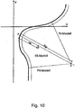
- the target astigmatism values in the periphery of the spectacle lens can be calculated by the so-called truncated cone model method.
- Fig. 10 illustrates the calculation of the target astigmatism values in the periphery of the spectacle lens according to the parallel curve model method (in US Pat FIG. 10 referred to as PK model) and after the truncated cone model method (in the FIG. 10 referred to as KS model).
- PK model parallel curve model method
- KS model truncated cone model method
- the truncated cone model method is used for calculating the desired astigmatism values in the periphery, and the parallel and curved model method is applied in the far and near part.
- a spectacle lens designer can quickly and efficiently generate or modify any progressive lens designs or any desired distributions of the target astigmatism.
- it is possible with the method according to the invention in an existing progressive lens design (start or basic design) to change the design characteristics quickly and efficiently and adapt them to customer needs.
- a significant advantage is therefore the avoidance of the overhead described above for the creation of suitable target specifications, in particular for individual progressive lenses.
- a further advantage is the possibility of setting the viewing areas arbitrarily and steplessly within given limits, without losing the design characteristic and the good imaging properties of the starting design.
- any number of design variations can be generated in order to always optimally respond to the needs of customers.
- the method according to the invention is particularly suitable for a database-driven calculation process.
- the base target isoastigmatism line is divided into three regions (far-range, .progression-range and near-range) by the specification of two vertical coordinates y F and y N.
- the course of the base target isoastigmatism line can be specified directly or, for example, either according to the Minkwitz theorem for a given refractive index along the main line or from a given starting surface, which is included in the start design, for example , be calculated.
- the lateral increase in astigmatism can be determined by the refractive power increase along the main line.
- the horizontal distances of the points of the boundary line from the main line and the u- coordinates of the base target isoastigmatism line can also be determined.
- the continuation or the course of the base target isoastigmatism line can be specified independently or (within defined limits) freely and steplessly changed and thus the design specification can be made.
- the base is isoastigmatism line in the progression zone (ie at y N ⁇ y ⁇ y F) not transformed.
- the derived individual design retains the characteristic property of the refractive index profile and associated minimal width of the progression channel of the startup design.
- the one-dimensional function f z ( y ) is continuously differentiable at least once.
- interpolation takes place between the main line and the second additional target isoastigmatism line and then between the second additional target isoastigmatism line and the base target isoastigmatism line.
- the additional second target isoastigmatism line can be predefined and calculated or modified analogously to the base target isoastigmatism line.
- the predetermined or predeterminable curve u ⁇ y , K : u ⁇ k ( u ), along which the first control point is displaced, may be an arbitrary curve.
- the curve is a straight line.
- the curve along which the second control point can be shifted may be any curve.
- this curve is a straight line.
- the base target isoastigmatism line passes through further control points.
- the other control points can be moved along corresponding predetermined or predeterminable curves, wherein the Calculation of the modified base target isoastigmatism line is carried out in such a way that it passes through the shifted control points.
- the first and optionally further control points can be freely selected e.g. depending on the individual preferences of the spectacle wearer or automatically based on captured individual customer data, such as customer preferences, weighting of individual preferences, application foci, frame properties, and / or other parameters.
- the maximum allowable displacement of the respective control point is set outwardly (i.e., toward the main line) and / or inwardly (i.e., in the direction toward the periphery of the lens).
- the orientation of the curves, and in particular the straight line along which the respective control point can be moved, can be arbitrary.
- the straight line along which the respective control point can move or move preferably coincides with the curve normal.
- the parameters of the modified base target isoastigmatism line and thus clearly the course of the modified base target isoastigmatism line can be determined unambiguously.
- the central area of the base target isoastigmatism line (ie the progression area) is from the refractive power course along the main line of sight
- one or two control points in the far and / or near part are generally sufficient to correspondingly modify the course of the base target isoastigmatism line or the course of the modified base target isoastigmatism line unambiguously to determine.
- the size of the viewing areas e.g. depending on the individual customer preferences, areas of use of the spectacle lens (sports, reading, etc.) and / or other individual customer parameters to modify and adapt to the individual situation of use.
- the control points can be moved in the Nahteil further outward and vice versa. If a very balanced lens design is to be created, then the control points can be shifted slightly inwards. Should e.g. from a balanced start design with arctangent representation in the remote part a sporty design with a large, wide remote part are generated, then the Nahteilbreite is reduced and the Fernteil maximized. In addition, from the arctangent representation to another representation, e.g. a polynomial representation, to be switched to e.g. no lateral field of view restrictions on large versions.
- another representation e.g. a polynomial representation
- the maximum allowed design changes can be set in advance, depending on the startup design.
- the displacement t and thus the field of view variables can be limited, where t a denotes the maximum permissible deviation to the outside and t i the maximum permissible deviation to the inside.
- the base target isoastigmatism line is changed to pass through the transformed control point or control points.
- the target values for the astigmatism distribution are determined or calculated by means of an interpolation as described above.
- the base target isoastigmatism line can be described by a series of suitable, one-dimensional, preferably at least once continuously differentiable functions f ( y ). It has surprisingly It has been pointed out that the function f ( y ) can already be suitably described by means of a few variable parameters, which considerably simplifies and accelerates the calculation and the transformation of the start design.
- the course of the base target isoastigmatism line is preferably given by a polynomial of order n :
- u G y a f + b f ⁇ y + c f ⁇ y n be described or specified with the parameters or coefficients a f , b f , c f (hereinafter also called short polynomial representation).
- a function of this kind is particularly suitable for describing a hard design.
- Arctangens representation for short.
- the base target isoastigmatism line runs through a first predetermined or predefinable control point r n ( u n , y n ) in the near part. This item is moved as described above r n ( u n , y n ) ⁇ r ' n ( u ' n , y ' n ).
- the course of the base target isoastigmatism line in the progression area extending between a vertical coordinate y N (at the limit to the near range) and a vertical coordinate y F (at the boundary to the far-end) does not vary, so that in this range (ie between y N and y F ) the base target isoastigmatism line of the starting design and the base target isoastigmatism line of the derived , individual designs coincide.
- Sollisoastigmatismusline in the remote part of a hard design can also be changed usually by the specification and manipulation of a control point.
- the base target isoastigmatism line has a first predetermined or predefinable control point r f ( u f , y f ) in the far end. This item is moved as described above: r f ( u f , y f ) ⁇ r ' f ( u ' f , y ' f ).
- the power n of the polynomial is usually specified or appropriately determined.
- the course of the base target isoastigmatism line can be modified, for example, directly or manually by the spectacle lens designer or automatically on the basis of individual data of the spectacle wearer in order to optimally adapt the visual areas (eg distance and / or short range) to the individual requirements of the respective spectacle wearer achieve.
- the modification of the course of the basic Sollisoastigmatismusline as described above by means of a modification of the position of at least one control point, wherein the change of the position of the at least one control point is done automatically based on individual data of the wearer.
- the course of the base target isoastigmatism line or the position of the at least one control point can be determined on the basis of individual preferences and requirements of the spectacle wearer, such as e.g. Preferences regarding the sizes of the far and / or near range, weighting of the visual areas (distance, near and intermediate or progression area), application emphases, and / or frame and centering data, in particular slice height and centering height, frame form) are automatically transformed.
- the individual data of the spectacle wearer may further include other individual parameters.
- the method further comprises a step of detecting individual parameters of the spectacle wearer.
- the individual data of a spectacle wearer ie the individual parameters and / or the individual requirements of a spectacle wearer can be queried in great detail, eg with a consulting tool such as "Consulting FreeSign ® " from Rodenstock GmbH.
- a consulting tool such as "Consulting FreeSign ® " from Rodenstock GmbH.
- the possible individual design proposals or design implementations are demonstrated directly to the customer. So far, the implementation of the individual requirements of the customer with regard to the viewing areas in corresponding flexible glass designs has not been satisfactorily solved.
- special designs such as "Impression Sport extracurved" from Rodenstock GmbH had to be avoided, which did not cover all near distances and base curves.
- a lateral expansion of the near range can be carried out, which can be combined, for example, with a reduction in the distance range or an increase in the gradients of the nominal isoastigmatism lines in the distance and / or near range, depending on the customer requirement profile (high weighting dynamics or remote part).
- the transformation of the start design further comprises transforming (eg, stretching or compressing in the vertical direction) the target astigmatism values calculated by interpolation in response to a variably adjustable, (individual) vertical position of the far and / or near reference points, such that the spectacle lens design to be calculated has the required vertical position of the distance and / or the near reference point.
- transforming eg, stretching or compressing in the vertical direction
- the target astigmatism values calculated by interpolation in response to a variably adjustable, (individual) vertical position of the far and / or near reference points
- a spectacle lens design has a predetermined spatial position of the distance and / or the near reference point if the prescribed or required for the wearer glasses values for the remote and / or Nahteil thanks (which are determined eg by means of refraction determination) are achieved in the respective reference point.
- the aberrations associated with the design in particular astigmatic deviation and refraction error, should be as small as possible (preferably substantially zero).
- a progressive lens design with arbitrary vertical position of the reference points for the distance and the proximity (far and near reference point) and main viewing areas can be derived and optimized while maintaining the design characteristic of the starting design.
- the vertical position and length of the progression zone of the progressive surface is automatically adapted to the individual user situation.
- an arbitrary position of the reference points for distance B F and proximity B N can be taken into account in the optimization of the spectacle lens.
- target values of the start design e.g., targets for refractive error, magnification, etc.
- targets for refractive error, magnification, etc. may also be appropriately transformed.
- the start-up design may further include a default for an object distance function along the main line of the spectacle lens.
- the method of calculating an individual design further comprises a suitable transformation of the object distance function of the startup design.
- the transformation coefficients of the transformation of the object distance function are determined by means of a Newtoniteration such that the refractive power of the spectacle lens in the far and / or near reference point of the individual spectacle lens design coincides with the refractive power of the spectacle lens in the far and / or near reference point of the start design.
- a suitable transformation of the object distance function is in the above-mentioned patent application PCT / EP 2008/000585 described.
- h ( I D / I ) a * ( I D / I ) + b , where a , b are constants.
- the start design may include a start target astigmatism distribution for the base addition Add B.
- This start-target astigmatism distribution can first be rescaled to obtain a desired astigmatism distribution for addition Add , where Add is the addition of the spectacle lens or lens design to be calculated.
- Add is the addition of the spectacle lens or lens design to be calculated.
- the course of the base target isoastigmatism line can be changed as described above, and a modified desired astigmatism distribution adapted to the new course of the base target isoastigmatism line can be determined by means of interpolation.
- the method according to the invention is suitable both for the generation of designs or design variants for conventional or effect-optimized progressive spectacle lenses, as well as for the generation of designs or design variants for individually optimized progressive spectacle lenses.
- any desired number of designs can be derived with just a few parameters from a balanced starting design (for example a universal design, a near design, etc.), the transitions being stepless.
- all designs derived from the start design preferably retain the same characteristic property of the refractive power progression along the main line and thus additionally also the minimum width in the progression channel. Consequently, it is possible with hindsight to produce almost all conceivable combinations of visual field variables and gradient curves, without it being necessary to work out a new design over the entire range of effects.
- the basic or start designs do not have to be modified directly, but rather just before the optimization the coefficients for generating the target specifications are adapted on the basis of the additional parameters, suitable application designs can be derived rapidly.
- the method according to the invention is particularly suitable for a calculation process controlled by a database. Since different design variants can be generated quickly and efficiently with the method according to the invention and tested against one another, the expenditure for the development and production of conventional, effect-optimized or individual progressive spectacle lenses can be considerably reduced.
- an adaptation to the freely definable positions of the near and / or distance reference points of the wearer of the spectacles and thus to different progression lengths can be performed.
- the existing optimization specifications or the existing start design can be arbitrarily stretched and compressed and thus adapted to the individual use situation and in particular to an individually determined progression length. Thereby no interpolation of the target specifications of different designs (eg different start designs, which have different progression length) is necessary.
- variants with different (longer or shorter) progression zones or progression lengths can be generated quickly and efficiently from an existing start design.
- the calculated spectacle lens design may be a spectacle lens design for a progressive spectacle lens having an object-side or, preferably, eye-side progressive surface.
- the opposite surface may preferably be a simple spherical or rotationally symmetric aspherical surface. It is also possible according to the method described above to calculate or produce a spectacle lens design for a double-progressive spectacle lens.
- an apparatus for designing a progressive spectacle lens design comprising design calculation means configured to perform a preferred method of designing a progressive spectacle lens.
- the device for generating or calculating a design for a progressive spectacle lens preferably comprises detection means which are designed to detect individual data of the spectacle wearer.
- the device for generating or calculating a design for a progressive spectacle lens preferably comprises detection means which are designed to detect individual data of the spectacle wearer.
- the starting design or starting specifications (comprising the specifications for the main line, for the target astigmatism values along the main line, for the course of at least one base target isoastigmatism line and possibly other parameters) can be stored permanently or temporarily in a memory.
- the design calculation and / or design transformation means which may in particular comprise calculation means for modifying the course of the base target isoastigmatism line, and / or the calculation means for generating or calculating a desired astigmatism distribution and / or their spatial distribution, may be implemented by means of appropriately configured or programmed conventional computers , specialized hardware and / or computer networks or computer systems are implemented.
- the design calculation and / or design transformation means and in particular the calculation means for modifying the course of the base target isoastigmatism line and / or the calculating means for generating or calculating a target astigmatism distribution and / or their spatial distribution can be in signal connection with the memory by means of suitable interfaces, and in particular read out and / or modify the data stored in the memory.
- the control point changing means may further include an interactive graphical user interface (GUI) that allows a user to change the positions of the control points.
- GUI graphical user interface
- a computer program product i. a computer program claimed in the claim category of a device, and a storage medium with computer program stored thereon, the computer program being designed, when loaded and executed on a computer, a preferred method according to the invention for generating or calculating a design for a progressive spectacle lens as described above perform.
- the manufacturing or processing can be done by numerically controlled CNC machines, by means of a casting process, a combination of the two methods or any other suitable method.
- the calculation or optimization of the spectacle lens is preferably carried out taking into account individual data of the spectacle wearer.
- the optimization and calculation means as well as the design calculation and / or design transformation means may be implemented by suitably configured or programmed computers, specialized hardware and / or computer networks, and so on. It is possible that the same computer or the same computer system is configured to program both the calculation of the design for the spectacle lens and the calculation or optimization of the spectacle lens according to the calculated design. However, it is of course possible that the calculation of the design and the calculation of the lens according to the calculated design in separate computing units, for example, in separate computers or computer systems.
- the device for producing a progressive spectacle lens preferably comprises processing means for finishing the spectacle lens.
- the processing means may e.g. CNC-controlled machines for direct processing of a blanket according to the determined optimization specifications.
- the finished spectacle lens preferably has a simple spherical or rotationally symmetric aspherical surface and a progressive surface optimized according to the design specifications calculated according to the invention and individual parameters of the spectacle wearer.
- the spherical or rotationally symmetric aspherical surface is the front surface (i.e., the object side surface) of the spectacle lens.
- the surface optimized according to the calculated design as the front surface of the spectacle lens.
- both surfaces of the spectacle lens are progressive surfaces.
- the device for producing a progressive spectacle lens further comprises detecting means for detecting individual data of the spectacle wearer, which in particular comprise data relating to the dioptric power of the spectacle lens required individually for the spectacle wearer.
- a spectacle lens produced according to a preferred production method can be used in a predetermined average or individual position of use of the spectacle lens in front of the eyes of a specific spectacle wearer for correcting defective vision of the spectacle wearer.
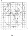
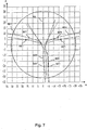
- the coordinate system of FIGS. 1 . 3 . 5 and 7 refers to a Cartesian coordinate system ⁇ x , y ⁇ of the eye-side progressive surface as defined above.
- the coordinate center coincides with the geometric center of the lens.
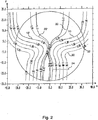
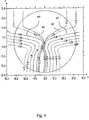
- the corresponding target astigmatism distributions ( Figures 2 . 4 . 6 and 8th ) are shown in the same coordinate system, with only the x-axis mirrored to the x-axis in FIGS. 1 . 3 . 5 and 7 is.
- Fig. 1 to 8 the respective distance from the coordinate origin in mm is plotted on the horizontal (x-axis) and the vertical axis.
- Fig. 1 shows the construction lines - main line, base target isoastigmatism line and additional target astigmatism line - of a first "soft" start design.
- Fig. 2 shows the corresponding target astigmatism distribution of the first "soft" start design.
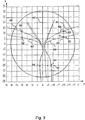
- FIG. 3 Figure 13 shows the design boundary lines - main line, base target isoastigmatism line and additional target isoastigmatism line - of a second, "hard" launch design.
- Fig. 4 shows the corresponding target astigmatism distribution of the second hard starter design Fig. 2 as well as in Fig. 4 the astigmatism distribution of the corresponding design is represented by means of target isoastigmatism lines.
- each of the starting designs shown has a main line (reference numeral 40 in FIG Fig. 1 and 70 in FIG Fig. 3 ), a nasal (reference numeral 10 in FIG Fig. 1 and 50 in FIG Fig. 3 ) and a temporal (reference numeral 10 'in FIG Fig. 1 and 50 'in FIG Fig. 3 ) 0.5 dpt base target isoastigmatism line.
- the start designs in the remote part or area each have a nasal (reference numeral 20 in FIG Fig. 1 and 60 on Fig. 3 ) and a temporal (reference numeral 20 'in FIG Fig. 1 and 60 'in FIG Fig. 3 ) additional 0.25 D target isoastigmatism line.
- the nasal 0.5 dpt base target isoastigmatism line 10 passes through a first 12 and a second 14 control point.
- the first control point 12 can be moved along the straight line 13 shown as an arrow and the second control point 14 along the straight line 15 shown as an arrow.
- the nasal additional target isoastigmatism line in the far part passes through a first 22 and a second 24 control point.
- the first control point can be moved along the straight line 23 shown as an arrow and the second control point along the straight line 25 shown as an arrow.
- the nasal base target isoastigmatism line runs through a third control point 16, which can be moved along the straight line 17 shown as an arrow.
- the construction of the base temporal isoastigmatism line 10 ' is the same as the construction of the base nasal isoastigmatism line.
- the temporal base target isoastigmatism line accordingly also runs through a first 12 ', a second 14' and a third 16 'control point.
- the construction of the additional target isoastigmatism line 20 ' is equal to the construction of the additional target isoastigmatism nasal line 20.
- the temporal additional target isoastigmatism line runs accordingly through a first 22 'and a second 24' control point.
- the nasal base target isoastigmatism line 50 of the in Fig. 3 shown start design by a first control point 52, which can be moved along the straight line 53 shown as arrow.
- the nasal base target isoastigmatism line 50 extends through a second control point 54, which can be moved along the straight line 55 shown as an arrow.
- the base temporal isoastigmatism line 50 ' has the same structure as the target nasal base isoastigmatism line 50.
- Reference numerals 52' and 54 ' denote the corresponding control points through which the temporal base target isoastigmatism line 50' passes.
- the nasal additional target isoastigmatism line 60 in the remote part has a first control point 62, which can be moved along the straight line 63 shown as an arrow.
- the temporal additional target isoastigmatism line 60 ' has a corresponding control point 62'.
- the distribution of Sollastigmatismus is determined.
- Both the first "soft” and the second “hard” start design are transformed, with no change between the base target isoastigmatism lines 10 and 10 'of the first start design and between a vertical coordinate y F and a vertical coordinate y N (ie in the progression region).
- the base target isoastigmatism lines 50 and 50 'of the second startup design are transformed, with no change between the base target isoastigmatism lines 10 and 10 'of the first start design and between a vertical coordinate y F and a vertical coordinate y N (ie in the progression region).
- Fig. 6 shows the target astigmatism distribution of the design derived from the first design.
- the derived progressive lens design has a wide near-end, but losses in the lateral remote part on.
- Fig. 8 shows the target astigmatism distribution of the derived from the second start design progressive lens design.
- the derived progressive addition lens design has a minimum near-end width and a large defect-free remote part.
- Fig. 9 schematically shows an exemplary process sequence in the production of a (individually optimized) progressive spectacle lens according to a determined progressive lens design, which is calculated according to a preferred method.
- a first step (S1) individual data of the spectacle wearer are recorded.
- the acquisition of the individual data of the spectacle wearer by means of suitable graphical user interfaces (GUI), which allow the input and possibly the change of the input individual data of the wearer.
- GUI graphical user interfaces
- the individual data of the spectacle wearer comprise in particular individual refraction data (sphere, cylinder, axis position, addition, prism and base), individual frame and centering data (disc height and centering height, frame shape) and individualization parameters or individual parameters of the eyes of the wearer and / or the individual Use situation or position of use of the spectacles in front of the eyes of the wearer of the spectacle (in particular pupil distance, corneal vertex distance, front inclination, frame disc angle, etc.).
- the frame and centering data may be provided by the user (e.g., an optometrist).
- the version data can be retrieved from a database.
- the individual parameters in particular pupil distance, corneal vertex distance, pretilt, socket disc angle
- the individual parameters can be determined, for example, automatically by means of a suitable 3-D measuring device, such as, for example. ImpressionIST of the company Rodenstock GmbH.
- the individual parameters can be determined with conventional measuring tools.
- the data relating to the type of spectacle lens (single-vision, bifocal, progressive) and the progression length of the precursor lens can be used to optimize the spatial position of the distance and near reference points, the optical effect, the course of the base target isoastigmatism line (or position and location of the vision areas ) etc. are taken into account.
- the data relating to the preceding lens may include data regarding improvement wishes compared to the previous spectacles, for example, greater distance range, larger intermediate range, greater near range, lower read reading or lower rocking motion.
- the individual data of the spectacle wearer may include data relating to the main use or data relating to the application areas (motoring, computer workstation, reading, crafts, etc.) of the progressive lens.
- the individual data of the spectacle wearer may also include data concerning the preferences regarding the visual areas (distance, near and intermediate or progression area).
- the query of these data can be done for example by means of suitable graphical user interfaces.
- These data are preferably also included in the calculation of the individual optimum size of the visual areas or of the individual optimal course of the base target isoastigmatism line and optionally in the calculation of the optimal position of the distance and / or the near reference point.
- corresponding weightings can be assigned to the individual visual areas.
- an ideal position of the reference points (distance and near reference point) with respect to the improvement wishes can be determined.
- data relating to the material (plastic / silicate) and / or the refractive index of the preceding glass can be detected and evaluated. If a progressive lens has already been worn, furthermore, the data relating to the preceding lens, data relating to the design of the spectacle lens (Hard / soft) and / or the type progressive lens (individual, conventional) include.
- suitable graphical user interfaces may be provided for entering and optionally correcting this data.
- the individual data preferably includes data relating to the individual object distances: working distance in reading (near-work), working distance in the distance, and / or data relating to the object distances in the refraction determination: distance and proximity.
- the distances to and distances from the object distances are preferably taken into account in the calculation and optimization of the individual design for the progressive spectacle lens and in the optimization of the individual spectacle lens.
- the individual data of the spectacle wearer are detected and evaluated and control the determination of the optimal course of the base target isoastigmatism line or the optimal size of the visual areas and preferably the optimal spatial position of the reference points distance and proximity.
- a second step (S2) an optimum course of the base target isoastigmatism line for a particular wearer in a specific situation of use and thus the optimal size and / or location of the visual areas (distance, near and progression areas) and optionally an optimal spatial position of the Distance and / or near reference point calculated on the basis of the collected individual data or fixed. This can be done manually or preferably automatically on the basis of the detected individual data.
- the optician can determine an "ideal" course of the base target isoastigmatism line (and thus the position and size of the visual areas) as well as an "ideal", individual position of the distance and / or near reference point itself for the glass order on the basis of the acquired individual data.
- the ideal course of the base target isoastigmatism line as well as the ideal position are calculated automatically from the detected preferences and possibly desired improvements with the aid of a computer.
- a further step (S3) is a progressive lens design or a proposal for a progressive lens design with the determined in the second step S2 optimal course of base Sollisoastigmatismusline and preferably with the determined optimal position of the far and near reference point according to a preferred method by means of a transformation of a given startup design 80.
- This design proposal is visualized by means of suitable graphical user interfaces, whereby the user is given the opportunity by changing the course of the base target isoastigmatism line (eg by shifting the control points) and optionally the individual position of the far and / or near reference point and / or a change in the individual customer data, in particular the preferences, the frame data, the weights, etc., to actively change the design.
- the change or adaptation of the course of the base target isoastigmatism line and, if appropriate, the position of the distance and / or near reference points and / or the preferences with respect to the viewing areas can be effected, for example, by means of a suitable graphical user interface.
- the new spectacle lens design is preferably calculated and visualized in real time. It is also preferable to visualize the difference or the change in the optical properties of the new lens design compared to the old lens design.
- the corresponding geometric data of a spectacle lens calculated according to the calculated (individual) design or design proposal can be calculated and also visualized by means of a suitable graphical user interface (preferably in the form of a three-dimensional model).
- a suitable graphical user interface preferably in the form of a three-dimensional model.
- cosmetic properties or data relating to the aesthetics of the spectacle lens for example, weight, geometric data such as overall height, maximum edge thickness, center thickness, etc.
- the visualization of the cosmetic properties of the spectacle lens can be done, for example, by means of a three-dimensional representation of a model of the spectacle lens with the geometric data determined.
- the representation of the cosmetic properties of the spectacle lens can e.g. be affected by a selection of the base curve and refractive index. The selection can be effect-dependent.
- visualization of visual comfort e.g., eye-tilt, swings, peripheral vision, distortions, etc.
- visual comfort e.g., eye-tilt, swings, peripheral vision, distortions, etc.
- an individual progressive spectacle lens is calculated or optimized according to the final individual design, wherein the Calculation or optimization of the lens also individual data regarding the wearer of glasses (such as individual use situation, frame data, data relating to the eyes of the wearer, etc.) are taken into account.
- the fully calculated or optimized spectacle lens can be produced, for example, by means of direct machining with numerically controlled machines, by means of a casting method or by means of other suitable methods, for example of glass or plastic (step S5).
- Fig. 10 illustrates the calculation of the target astigmatism values in the periphery of the spectacle lens according to the parallel curve model method (in US Pat FIG. 10 referred to as PK model) and the truncated cone model method (in the FIG. 10 referred to as KS model).
- PK model parallel curve model method
- KS model truncated cone model method
Landscapes
- Physics & Mathematics (AREA)
- Health & Medical Sciences (AREA)
- Ophthalmology & Optometry (AREA)
- General Health & Medical Sciences (AREA)
- General Physics & Mathematics (AREA)
- Optics & Photonics (AREA)
- Mathematical Physics (AREA)
- Eyeglasses (AREA)
Applications Claiming Priority (2)
| Application Number | Priority Date | Filing Date | Title |
|---|---|---|---|
| DE102009005206A DE102009005206A1 (de) | 2009-01-20 | 2009-01-20 | Variables Gleitsichtglasdesign |
| PCT/EP2009/009194 WO2010083868A1 (de) | 2009-01-20 | 2009-12-21 | Variables gleitsichtglasdesign |
Publications (2)
| Publication Number | Publication Date |
|---|---|
| EP2389610A1 EP2389610A1 (de) | 2011-11-30 |
| EP2389610B1 true EP2389610B1 (de) | 2015-01-14 |
Family
ID=42078933
Family Applications (1)
| Application Number | Title | Priority Date | Filing Date |
|---|---|---|---|
| EP09801668.6A Active EP2389610B1 (de) | 2009-01-20 | 2009-12-21 | Variables gleitsichtglasdesign |
Country Status (5)
| Country | Link |
|---|---|
| US (1) | US8998409B2 (enExample) |
| EP (1) | EP2389610B1 (enExample) |
| JP (1) | JP5666472B2 (enExample) |
| DE (1) | DE102009005206A1 (enExample) |
| WO (1) | WO2010083868A1 (enExample) |
Families Citing this family (14)
| Publication number | Priority date | Publication date | Assignee | Title |
|---|---|---|---|---|
| US9354455B2 (en) | 2009-01-23 | 2016-05-31 | Rodenstock Gmbh | Controlling designs using a polygonal design |
| EP2270577A1 (en) * | 2009-06-30 | 2011-01-05 | Essilor International (Compagnie Générale D'Optique) | Method of and apparatus for generating a surface of an optical lens |
| DE102010049168A1 (de) | 2010-10-21 | 2012-04-26 | Rodenstock Gmbh | Verordnungs- und individualisierungsabhängige Modifikation des temporalen peripheren Sollastigmatismus und Anpassung der Objektabstandsfunktion an veränderte Objektabstände für die Nähe und/oder die Ferne |
| EP2490065A1 (en) * | 2011-02-18 | 2012-08-22 | ESSILOR INTERNATIONAL (Compagnie Générale d'Optique) | A method for determining target optical functions |
| WO2013086137A1 (en) | 2011-12-06 | 2013-06-13 | 1-800 Contacts, Inc. | Systems and methods for obtaining a pupillary distance measurement using a mobile computing device |
| US20130297061A1 (en) * | 2012-05-03 | 2013-11-07 | National Taiwan University | Method and computer-aided design system of manufacturing an optical system |
| US9483853B2 (en) | 2012-05-23 | 2016-11-01 | Glasses.Com Inc. | Systems and methods to display rendered images |
| DE102012010221A1 (de) * | 2012-05-23 | 2013-11-28 | Carl Zeiss Vision International Gmbh | Verfahren zum Herstellen einer Brillenlinse mit astigmatischer Korrektur und Brille mit solcher Brillenlinse |
| US9311746B2 (en) | 2012-05-23 | 2016-04-12 | Glasses.Com Inc. | Systems and methods for generating a 3-D model of a virtual try-on product |
| US9286715B2 (en) | 2012-05-23 | 2016-03-15 | Glasses.Com Inc. | Systems and methods for adjusting a virtual try-on |
| WO2016111851A1 (en) * | 2015-01-09 | 2016-07-14 | Amo Development, Llc | Vergence weighting systems and methods for treatment of presbyopia and other vision conditions |
| EP3563195A1 (en) * | 2016-12-30 | 2019-11-06 | Hoya Lens Thailand Ltd. | Method for designing spectacle lenses, lenses and devices for designing the same |
| PT3352001T (pt) * | 2017-01-20 | 2023-06-16 | Zeiss Carl Vision Int Gmbh | Lente de óculos progressiva com índice de refração variável e método para a sua conceção e produção |
| US10007128B1 (en) * | 2017-10-02 | 2018-06-26 | Carl Zeiss Vision International Gmbh | Method and device for establishing a target design |
Family Cites Families (16)
| Publication number | Priority date | Publication date | Assignee | Title |
|---|---|---|---|---|
| DE100188C (enExample) | ||||
| US6199983B1 (en) | 1996-10-14 | 2001-03-13 | Seiko Epson Corporation | Apparatus and method for manufacturing a progressive multi-focal lens |
| JP2001076177A (ja) | 1999-09-06 | 2001-03-23 | Fujitsu Ltd | ポリゴンリダクション処理を用いたモーフィング画像処理装置および方法 |
| JP4959087B2 (ja) | 2000-04-25 | 2012-06-20 | ローデンストック.ゲゼルシャフト.ミット.ベシュレンクテル.ハフツング | プログレッシブ眼鏡レンズの計算方法と、この種の眼鏡レンズの製造方法 |
| AU2002953061A0 (en) | 2002-11-20 | 2002-12-19 | Sola International Holdings Ltd | Method for designing progressive lenses |
| DE10313275A1 (de) * | 2003-03-24 | 2004-10-14 | Rodenstock Gmbh | Verfahren zum Berechnen eines individuellen Progressivglases |
| JP4846985B2 (ja) * | 2004-04-20 | 2011-12-28 | セイコーオプティカルプロダクツ株式会社 | 光学特性補間方法、眼鏡装用シミュレーション画像処理方法、眼鏡装用シミュレーション画像処理装置、眼鏡レンズの評価方法、眼鏡レンズの評価装置 |
| US7229173B2 (en) * | 2004-08-25 | 2007-06-12 | Essilor International (Compagnie Generale D'optique) S.A. | Short corridor progressive addition lenses with reduced unwanted astigmatism |
| WO2007004070A1 (en) * | 2005-06-20 | 2007-01-11 | Essilor International (Compagnie Generale D'optique) | Short channel progressive addition lenses |
| EP1752815A1 (en) * | 2005-08-11 | 2007-02-14 | Essilor International (Compagnie Generale D'optique) | Method of manufacturing an optical system |
| FR2898193B1 (fr) | 2006-03-01 | 2008-05-09 | Essilor Int | Procede de determination d'une lentille ophtalmique progressive. |
| ATE514118T1 (de) * | 2007-01-25 | 2011-07-15 | Rodenstock Gmbh | Flexibler gleitsichtglasoptimierer |
| EP2124712B1 (de) | 2007-01-25 | 2014-03-05 | Rodenstock GmbH | Verfahren zur bestimmung der bezugspunkte fern und nah |
| JP5642390B2 (ja) * | 2007-01-25 | 2014-12-17 | ローデンストック.ゲゼルシャフト.ミット.ベシュレンクテル.ハフツング | 様々な位置の基準点を有する眼鏡レンズの計算方法 |
| AU2008332369B2 (en) * | 2007-12-04 | 2011-09-08 | Hoya Corporation | Pair of progressive power lens and method for designing same |
| DE102008015189A1 (de) * | 2008-03-20 | 2009-10-01 | Rodenstock Gmbh | Umskalierung des Sollastigmatismus für andere Additionen |
-
2009
- 2009-01-20 DE DE102009005206A patent/DE102009005206A1/de not_active Ceased
- 2009-12-21 US US13/145,508 patent/US8998409B2/en active Active
- 2009-12-21 WO PCT/EP2009/009194 patent/WO2010083868A1/de not_active Ceased
- 2009-12-21 EP EP09801668.6A patent/EP2389610B1/de active Active
- 2009-12-21 JP JP2011545636A patent/JP5666472B2/ja active Active
Also Published As
| Publication number | Publication date |
|---|---|
| WO2010083868A1 (de) | 2010-07-29 |
| EP2389610A1 (de) | 2011-11-30 |
| JP5666472B2 (ja) | 2015-02-12 |
| JP2012515934A (ja) | 2012-07-12 |
| US20120002161A1 (en) | 2012-01-05 |
| US8998409B2 (en) | 2015-04-07 |
| DE102009005206A1 (de) | 2010-07-22 |
Similar Documents
| Publication | Publication Date | Title |
|---|---|---|
| EP2389610B1 (de) | Variables gleitsichtglasdesign | |
| EP2389609B1 (de) | Automatische gleitsichtglasdesignmodifikation | |
| EP2115525B1 (de) | Flexibler gleitsichtglasoptimierer | |
| EP2115524B1 (de) | Verfahren zur berechnung eines brillenglases mit variabler lage der bezugspunkte | |
| EP2263114B1 (de) | Umskalierung des sollastigmatismus für andere additionen | |
| EP2124712B1 (de) | Verfahren zur bestimmung der bezugspunkte fern und nah | |
| EP2389611B1 (de) | Designsteuerung mittels eines designvielecks | |
| EP3598214B1 (de) | Gleitsicht-brillenglas mit variablem brechungsindex und verfahren zu dessen entwurf und herstellung | |
| EP2564262B1 (de) | Verfahren zur berechnung eines brillenglases mit blickwinkelabhängigen verordnungsdaten | |
| EP2767862B1 (de) | Verordnungs- und individualisierungsabhängige anpassung der objektabstandsfunktion an veränderte objektabstände für die nähe und/oder ferne | |
| EP4193217A1 (de) | Verbesserte berechnung ophthalmischer linsen | |
| EP3814828B1 (de) | Computerimplementiertes verfahren, datenverarbeitungssystem zum erzeugen eines zieldesigns sowie computerprogramm, speichermedium mit instruktionen zum erzeugen eines zieldesigns, verfahren zum bereitstellen eines brillenglases, speichermedium mit einer numerischen darstellung eines brillenglases und verfahren zum herstellen eines brillenglases | |
| DE102015205721B4 (de) | Verfahren zum Erstellen eines Designs einer Rezeptfläche einer Multifokallinse und Multifokallinse mit einer solchen Rezeptfläche | |
| DE102017118219B4 (de) | Computerimplementiertes Verfahren zum Erstellen eines Zieldesigns für die Optimierung einer Freiformfläche eines Brillenglases, Computerprogramm, Speichermedium, Computer sowie Vorrichtung | |
| WO2018137962A1 (de) | Verfahren zur berücksichtigung unterschiedlicher prismatischer korrekturen in der ferne und der nähe | |
| WO2019141386A1 (de) | Gleitsicht-brillenglas mit variablem brechungsindex und verfahren zu dessen entwurf und herstellung |
Legal Events
| Date | Code | Title | Description |
|---|---|---|---|
| PUAI | Public reference made under article 153(3) epc to a published international application that has entered the european phase |
Free format text: ORIGINAL CODE: 0009012 |
|
| 17P | Request for examination filed |
Effective date: 20110804 |
|
| AK | Designated contracting states |
Kind code of ref document: A1 Designated state(s): AT BE BG CH CY CZ DE DK EE ES FI FR GB GR HR HU IE IS IT LI LT LU LV MC MK MT NL NO PL PT RO SE SI SK SM TR |
|
| DAX | Request for extension of the european patent (deleted) | ||
| RAP1 | Party data changed (applicant data changed or rights of an application transferred) |
Owner name: RODENSTOCK GMBH |
|
| RIC1 | Information provided on ipc code assigned before grant |
Ipc: G02C 7/02 20060101AFI20140522BHEP Ipc: G02C 7/06 20060101ALI20140522BHEP |
|
| GRAP | Despatch of communication of intention to grant a patent |
Free format text: ORIGINAL CODE: EPIDOSNIGR1 |
|
| INTG | Intention to grant announced |
Effective date: 20140701 |
|
| GRAP | Despatch of communication of intention to grant a patent |
Free format text: ORIGINAL CODE: EPIDOSNIGR1 |
|
| INTG | Intention to grant announced |
Effective date: 20140905 |
|
| GRAS | Grant fee paid |
Free format text: ORIGINAL CODE: EPIDOSNIGR3 |
|
| 111Z | Information provided on other rights and legal means of execution |
Free format text: AT BE BG CH CY CZ DE DK EE ES FI FR GB GR HR HU IE IS IT LT LU LV MC MK MT NL NO PL PT RO SE SI SK SM TR Effective date: 20141010 |
|
| GRAA | (expected) grant |
Free format text: ORIGINAL CODE: 0009210 |
|
| AK | Designated contracting states |
Kind code of ref document: B1 Designated state(s): AT BE BG CH CY CZ DE DK EE ES FI FR GB GR HR HU IE IS IT LI LT LU LV MC MK MT NL NO PL PT RO SE SI SK SM TR |
|
| REG | Reference to a national code |
Ref country code: GB Ref legal event code: FG4D Free format text: NOT ENGLISH |
|
| REG | Reference to a national code |
Ref country code: CH Ref legal event code: EP |
|
| REG | Reference to a national code |
Ref country code: IE Ref legal event code: FG4D Free format text: LANGUAGE OF EP DOCUMENT: GERMAN |
|
| REG | Reference to a national code |
Ref country code: AT Ref legal event code: REF Ref document number: 707354 Country of ref document: AT Kind code of ref document: T Effective date: 20150215 |
|
| REG | Reference to a national code |
Ref country code: DE Ref legal event code: R096 Ref document number: 502009010515 Country of ref document: DE Effective date: 20150305 |
|
| REG | Reference to a national code |
Ref country code: NL Ref legal event code: VDEP Effective date: 20150114 |
|
| REG | Reference to a national code |
Ref country code: LT Ref legal event code: MG4D |
|
| PG25 | Lapsed in a contracting state [announced via postgrant information from national office to epo] |
Ref country code: LT Free format text: LAPSE BECAUSE OF FAILURE TO SUBMIT A TRANSLATION OF THE DESCRIPTION OR TO PAY THE FEE WITHIN THE PRESCRIBED TIME-LIMIT Effective date: 20150114 Ref country code: SE Free format text: LAPSE BECAUSE OF FAILURE TO SUBMIT A TRANSLATION OF THE DESCRIPTION OR TO PAY THE FEE WITHIN THE PRESCRIBED TIME-LIMIT Effective date: 20150114 Ref country code: ES Free format text: LAPSE BECAUSE OF FAILURE TO SUBMIT A TRANSLATION OF THE DESCRIPTION OR TO PAY THE FEE WITHIN THE PRESCRIBED TIME-LIMIT Effective date: 20150114 Ref country code: FI Free format text: LAPSE BECAUSE OF FAILURE TO SUBMIT A TRANSLATION OF THE DESCRIPTION OR TO PAY THE FEE WITHIN THE PRESCRIBED TIME-LIMIT Effective date: 20150114 Ref country code: NO Free format text: LAPSE BECAUSE OF FAILURE TO SUBMIT A TRANSLATION OF THE DESCRIPTION OR TO PAY THE FEE WITHIN THE PRESCRIBED TIME-LIMIT Effective date: 20150414 Ref country code: HR Free format text: LAPSE BECAUSE OF FAILURE TO SUBMIT A TRANSLATION OF THE DESCRIPTION OR TO PAY THE FEE WITHIN THE PRESCRIBED TIME-LIMIT Effective date: 20150114 Ref country code: BG Free format text: LAPSE BECAUSE OF FAILURE TO SUBMIT A TRANSLATION OF THE DESCRIPTION OR TO PAY THE FEE WITHIN THE PRESCRIBED TIME-LIMIT Effective date: 20150414 |
|
| PG25 | Lapsed in a contracting state [announced via postgrant information from national office to epo] |
Ref country code: GR Free format text: LAPSE BECAUSE OF FAILURE TO SUBMIT A TRANSLATION OF THE DESCRIPTION OR TO PAY THE FEE WITHIN THE PRESCRIBED TIME-LIMIT Effective date: 20150415 Ref country code: IS Free format text: LAPSE BECAUSE OF FAILURE TO SUBMIT A TRANSLATION OF THE DESCRIPTION OR TO PAY THE FEE WITHIN THE PRESCRIBED TIME-LIMIT Effective date: 20150514 Ref country code: LV Free format text: LAPSE BECAUSE OF FAILURE TO SUBMIT A TRANSLATION OF THE DESCRIPTION OR TO PAY THE FEE WITHIN THE PRESCRIBED TIME-LIMIT Effective date: 20150114 Ref country code: NL Free format text: LAPSE BECAUSE OF FAILURE TO SUBMIT A TRANSLATION OF THE DESCRIPTION OR TO PAY THE FEE WITHIN THE PRESCRIBED TIME-LIMIT Effective date: 20150114 Ref country code: PL Free format text: LAPSE BECAUSE OF FAILURE TO SUBMIT A TRANSLATION OF THE DESCRIPTION OR TO PAY THE FEE WITHIN THE PRESCRIBED TIME-LIMIT Effective date: 20150114 |
|
| REG | Reference to a national code |
Ref country code: DE Ref legal event code: R097 Ref document number: 502009010515 Country of ref document: DE |
|
| PG25 | Lapsed in a contracting state [announced via postgrant information from national office to epo] |
Ref country code: EE Free format text: LAPSE BECAUSE OF FAILURE TO SUBMIT A TRANSLATION OF THE DESCRIPTION OR TO PAY THE FEE WITHIN THE PRESCRIBED TIME-LIMIT Effective date: 20150114 Ref country code: RO Free format text: LAPSE BECAUSE OF FAILURE TO SUBMIT A TRANSLATION OF THE DESCRIPTION OR TO PAY THE FEE WITHIN THE PRESCRIBED TIME-LIMIT Effective date: 20150114 Ref country code: SK Free format text: LAPSE BECAUSE OF FAILURE TO SUBMIT A TRANSLATION OF THE DESCRIPTION OR TO PAY THE FEE WITHIN THE PRESCRIBED TIME-LIMIT Effective date: 20150114 Ref country code: CZ Free format text: LAPSE BECAUSE OF FAILURE TO SUBMIT A TRANSLATION OF THE DESCRIPTION OR TO PAY THE FEE WITHIN THE PRESCRIBED TIME-LIMIT Effective date: 20150114 Ref country code: DK Free format text: LAPSE BECAUSE OF FAILURE TO SUBMIT A TRANSLATION OF THE DESCRIPTION OR TO PAY THE FEE WITHIN THE PRESCRIBED TIME-LIMIT Effective date: 20150114 |
|
| PLBE | No opposition filed within time limit |
Free format text: ORIGINAL CODE: 0009261 |
|
| STAA | Information on the status of an ep patent application or granted ep patent |
Free format text: STATUS: NO OPPOSITION FILED WITHIN TIME LIMIT |
|
| 26N | No opposition filed |
Effective date: 20151015 |
|
| PG25 | Lapsed in a contracting state [announced via postgrant information from national office to epo] |
Ref country code: IT Free format text: LAPSE BECAUSE OF FAILURE TO SUBMIT A TRANSLATION OF THE DESCRIPTION OR TO PAY THE FEE WITHIN THE PRESCRIBED TIME-LIMIT Effective date: 20150114 |
|
| PG25 | Lapsed in a contracting state [announced via postgrant information from national office to epo] |
Ref country code: SI Free format text: LAPSE BECAUSE OF FAILURE TO SUBMIT A TRANSLATION OF THE DESCRIPTION OR TO PAY THE FEE WITHIN THE PRESCRIBED TIME-LIMIT Effective date: 20150114 |
|
| PG25 | Lapsed in a contracting state [announced via postgrant information from national office to epo] |
Ref country code: BE Free format text: LAPSE BECAUSE OF NON-PAYMENT OF DUE FEES Effective date: 20151231 |
|
| PG25 | Lapsed in a contracting state [announced via postgrant information from national office to epo] |
Ref country code: LU Free format text: LAPSE BECAUSE OF FAILURE TO SUBMIT A TRANSLATION OF THE DESCRIPTION OR TO PAY THE FEE WITHIN THE PRESCRIBED TIME-LIMIT Effective date: 20151221 Ref country code: MC Free format text: LAPSE BECAUSE OF FAILURE TO SUBMIT A TRANSLATION OF THE DESCRIPTION OR TO PAY THE FEE WITHIN THE PRESCRIBED TIME-LIMIT Effective date: 20150114 |
|
| REG | Reference to a national code |
Ref country code: CH Ref legal event code: PL |
|
| REG | Reference to a national code |
Ref country code: FR Ref legal event code: PLFP Year of fee payment: 8 |
|
| REG | Reference to a national code |
Ref country code: IE Ref legal event code: MM4A |
|
| PG25 | Lapsed in a contracting state [announced via postgrant information from national office to epo] |
Ref country code: LI Free format text: LAPSE BECAUSE OF NON-PAYMENT OF DUE FEES Effective date: 20151231 Ref country code: IE Free format text: LAPSE BECAUSE OF NON-PAYMENT OF DUE FEES Effective date: 20151221 Ref country code: CH Free format text: LAPSE BECAUSE OF NON-PAYMENT OF DUE FEES Effective date: 20151231 |
|
| REG | Reference to a national code |
Ref country code: AT Ref legal event code: MM01 Ref document number: 707354 Country of ref document: AT Kind code of ref document: T Effective date: 20151221 |
|
| PG25 | Lapsed in a contracting state [announced via postgrant information from national office to epo] |
Ref country code: SM Free format text: LAPSE BECAUSE OF FAILURE TO SUBMIT A TRANSLATION OF THE DESCRIPTION OR TO PAY THE FEE WITHIN THE PRESCRIBED TIME-LIMIT Effective date: 20150114 Ref country code: HU Free format text: LAPSE BECAUSE OF FAILURE TO SUBMIT A TRANSLATION OF THE DESCRIPTION OR TO PAY THE FEE WITHIN THE PRESCRIBED TIME-LIMIT; INVALID AB INITIO Effective date: 20091221 Ref country code: AT Free format text: LAPSE BECAUSE OF NON-PAYMENT OF DUE FEES Effective date: 20151221 |
|
| PG25 | Lapsed in a contracting state [announced via postgrant information from national office to epo] |
Ref country code: CY Free format text: LAPSE BECAUSE OF FAILURE TO SUBMIT A TRANSLATION OF THE DESCRIPTION OR TO PAY THE FEE WITHIN THE PRESCRIBED TIME-LIMIT Effective date: 20150114 |
|
| REG | Reference to a national code |
Ref country code: FR Ref legal event code: PLFP Year of fee payment: 9 |
|
| PG25 | Lapsed in a contracting state [announced via postgrant information from national office to epo] |
Ref country code: MT Free format text: LAPSE BECAUSE OF FAILURE TO SUBMIT A TRANSLATION OF THE DESCRIPTION OR TO PAY THE FEE WITHIN THE PRESCRIBED TIME-LIMIT Effective date: 20150114 Ref country code: TR Free format text: LAPSE BECAUSE OF FAILURE TO SUBMIT A TRANSLATION OF THE DESCRIPTION OR TO PAY THE FEE WITHIN THE PRESCRIBED TIME-LIMIT Effective date: 20150114 |
|
| PG25 | Lapsed in a contracting state [announced via postgrant information from national office to epo] |
Ref country code: PT Free format text: LAPSE BECAUSE OF FAILURE TO SUBMIT A TRANSLATION OF THE DESCRIPTION OR TO PAY THE FEE WITHIN THE PRESCRIBED TIME-LIMIT Effective date: 20150114 Ref country code: MK Free format text: LAPSE BECAUSE OF FAILURE TO SUBMIT A TRANSLATION OF THE DESCRIPTION OR TO PAY THE FEE WITHIN THE PRESCRIBED TIME-LIMIT Effective date: 20150114 |
|
| PGFP | Annual fee paid to national office [announced via postgrant information from national office to epo] |
Ref country code: DE Payment date: 20241219 Year of fee payment: 16 |
|
| PGFP | Annual fee paid to national office [announced via postgrant information from national office to epo] |
Ref country code: GB Payment date: 20241218 Year of fee payment: 16 |
|
| PGFP | Annual fee paid to national office [announced via postgrant information from national office to epo] |
Ref country code: FR Payment date: 20241218 Year of fee payment: 16 |