EP2389509B1 - Stationary energy production plant having a braking device - Google Patents
Stationary energy production plant having a braking device Download PDFInfo
- Publication number
- EP2389509B1 EP2389509B1 EP09801411A EP09801411A EP2389509B1 EP 2389509 B1 EP2389509 B1 EP 2389509B1 EP 09801411 A EP09801411 A EP 09801411A EP 09801411 A EP09801411 A EP 09801411A EP 2389509 B1 EP2389509 B1 EP 2389509B1
- Authority
- EP
- European Patent Office
- Prior art keywords
- braking
- braking device
- energy production
- production plant
- rotor
- Prior art date
- Legal status (The legal status is an assumption and is not a legal conclusion. Google has not performed a legal analysis and makes no representation as to the accuracy of the status listed.)
- Not-in-force
Links
- 238000004519 manufacturing process Methods 0.000 title claims abstract description 22
- 239000012530 fluid Substances 0.000 claims abstract description 3
- 238000000034 method Methods 0.000 claims description 16
- 230000005540 biological transmission Effects 0.000 description 19
- 238000010248 power generation Methods 0.000 description 15
- 238000010586 diagram Methods 0.000 description 7
- 238000011084 recovery Methods 0.000 description 6
- 230000001276 controlling effect Effects 0.000 description 2
- 238000000594 atomic force spectroscopy Methods 0.000 description 1
- 230000001419 dependent effect Effects 0.000 description 1
- 238000001514 detection method Methods 0.000 description 1
- 238000011161 development Methods 0.000 description 1
- 230000018109 developmental process Effects 0.000 description 1
- 230000000694 effects Effects 0.000 description 1
- 230000003534 oscillatory effect Effects 0.000 description 1
- 230000001105 regulatory effect Effects 0.000 description 1
- 238000001228 spectrum Methods 0.000 description 1
- 230000003068 static effect Effects 0.000 description 1
Images

Classifications
-
- F—MECHANICAL ENGINEERING; LIGHTING; HEATING; WEAPONS; BLASTING
- F03—MACHINES OR ENGINES FOR LIQUIDS; WIND, SPRING, OR WEIGHT MOTORS; PRODUCING MECHANICAL POWER OR A REACTIVE PROPULSIVE THRUST, NOT OTHERWISE PROVIDED FOR
- F03D—WIND MOTORS
- F03D7/00—Controlling wind motors
- F03D7/02—Controlling wind motors the wind motors having rotation axis substantially parallel to the air flow entering the rotor
- F03D7/04—Automatic control; Regulation
- F03D7/042—Automatic control; Regulation by means of an electrical or electronic controller
-
- F—MECHANICAL ENGINEERING; LIGHTING; HEATING; WEAPONS; BLASTING
- F03—MACHINES OR ENGINES FOR LIQUIDS; WIND, SPRING, OR WEIGHT MOTORS; PRODUCING MECHANICAL POWER OR A REACTIVE PROPULSIVE THRUST, NOT OTHERWISE PROVIDED FOR
- F03D—WIND MOTORS
- F03D7/00—Controlling wind motors
- F03D7/02—Controlling wind motors the wind motors having rotation axis substantially parallel to the air flow entering the rotor
- F03D7/0244—Controlling wind motors the wind motors having rotation axis substantially parallel to the air flow entering the rotor for braking
- F03D7/0248—Controlling wind motors the wind motors having rotation axis substantially parallel to the air flow entering the rotor for braking by mechanical means acting on the power train
-
- F—MECHANICAL ENGINEERING; LIGHTING; HEATING; WEAPONS; BLASTING
- F05—INDEXING SCHEMES RELATING TO ENGINES OR PUMPS IN VARIOUS SUBCLASSES OF CLASSES F01-F04
- F05B—INDEXING SCHEME RELATING TO WIND, SPRING, WEIGHT, INERTIA OR LIKE MOTORS, TO MACHINES OR ENGINES FOR LIQUIDS COVERED BY SUBCLASSES F03B, F03D AND F03G
- F05B2260/00—Function
- F05B2260/90—Braking
- F05B2260/904—Braking using hydrodynamic forces
-
- F—MECHANICAL ENGINEERING; LIGHTING; HEATING; WEAPONS; BLASTING
- F05—INDEXING SCHEMES RELATING TO ENGINES OR PUMPS IN VARIOUS SUBCLASSES OF CLASSES F01-F04
- F05B—INDEXING SCHEME RELATING TO WIND, SPRING, WEIGHT, INERTIA OR LIKE MOTORS, TO MACHINES OR ENGINES FOR LIQUIDS COVERED BY SUBCLASSES F03B, F03D AND F03G
- F05B2270/00—Control
- F05B2270/10—Purpose of the control system
- F05B2270/101—Purpose of the control system to control rotational speed (n)
- F05B2270/1011—Purpose of the control system to control rotational speed (n) to prevent overspeed
-
- F—MECHANICAL ENGINEERING; LIGHTING; HEATING; WEAPONS; BLASTING
- F05—INDEXING SCHEMES RELATING TO ENGINES OR PUMPS IN VARIOUS SUBCLASSES OF CLASSES F01-F04
- F05B—INDEXING SCHEME RELATING TO WIND, SPRING, WEIGHT, INERTIA OR LIKE MOTORS, TO MACHINES OR ENGINES FOR LIQUIDS COVERED BY SUBCLASSES F03B, F03D AND F03G
- F05B2270/00—Control
- F05B2270/10—Purpose of the control system
- F05B2270/1016—Purpose of the control system in variable speed operation
-
- F—MECHANICAL ENGINEERING; LIGHTING; HEATING; WEAPONS; BLASTING
- F05—INDEXING SCHEMES RELATING TO ENGINES OR PUMPS IN VARIOUS SUBCLASSES OF CLASSES F01-F04
- F05B—INDEXING SCHEME RELATING TO WIND, SPRING, WEIGHT, INERTIA OR LIKE MOTORS, TO MACHINES OR ENGINES FOR LIQUIDS COVERED BY SUBCLASSES F03B, F03D AND F03G
- F05B2270/00—Control
- F05B2270/10—Purpose of the control system
- F05B2270/103—Purpose of the control system to affect the output of the engine
- F05B2270/1032—Torque
-
- F—MECHANICAL ENGINEERING; LIGHTING; HEATING; WEAPONS; BLASTING
- F05—INDEXING SCHEMES RELATING TO ENGINES OR PUMPS IN VARIOUS SUBCLASSES OF CLASSES F01-F04
- F05B—INDEXING SCHEME RELATING TO WIND, SPRING, WEIGHT, INERTIA OR LIKE MOTORS, TO MACHINES OR ENGINES FOR LIQUIDS COVERED BY SUBCLASSES F03B, F03D AND F03G
- F05B2270/00—Control
- F05B2270/10—Purpose of the control system
- F05B2270/107—Purpose of the control system to cope with emergencies
-
- Y—GENERAL TAGGING OF NEW TECHNOLOGICAL DEVELOPMENTS; GENERAL TAGGING OF CROSS-SECTIONAL TECHNOLOGIES SPANNING OVER SEVERAL SECTIONS OF THE IPC; TECHNICAL SUBJECTS COVERED BY FORMER USPC CROSS-REFERENCE ART COLLECTIONS [XRACs] AND DIGESTS
- Y02—TECHNOLOGIES OR APPLICATIONS FOR MITIGATION OR ADAPTATION AGAINST CLIMATE CHANGE
- Y02E—REDUCTION OF GREENHOUSE GAS [GHG] EMISSIONS, RELATED TO ENERGY GENERATION, TRANSMISSION OR DISTRIBUTION
- Y02E10/00—Energy generation through renewable energy sources
- Y02E10/70—Wind energy
- Y02E10/72—Wind turbines with rotation axis in wind direction
Definitions
- the invention relates to an energy recovery system with a braking device.
- the energy recovery system has at least one rotor driven by a fluid and a generator coupled to the rotor.
- the braking device is arranged on a shaft of the drive train.
- a braking device for braking a rotor of a wind turbine has at least one hydraulically actuable brake cylinder whose brake pressure can be regulated by means of a continuously adjustable control valve.
- the braking device has a drain line from this directional valve to a tank, wherein a check valve is arranged, which allows a leak-free shut off the pressure medium flow path to the tank.
- Such a braking device solves the task of braking a rotor of a wind turbine to ensure a leak-tight shut-off of a hydraulically actuated brake cylinder.
- a safe Bremstik- or brake release pressure modulation with high accuracy is possible, so that a smooth braking of the rotor is ensured.
- Such a braking device has the disadvantage that it emergency situations in which a rotor of a wind turbine is to be braked in the shortest possible time is not fair. Rather, the gentle deceleration is a deceleration process theoretically close to an aperiodic limit case, since any overshoot is suppressed by the braking force is metered so that a steep torque increase, as in emergency situations to decelerate a. Rotor of a wind turbine would be required in a very short time, with such a braking device is not feasible.
- the US 6,254,197 B1 discloses a hydraulic brake system and a method for controlling the hydraulic brake system for a stationary power plant, in particular for wind turbines, conveyor systems and the like.
- the control of the hydraulic braking system acts on the drive train by limiting the torque introduced by the brake system.
- the braking force is thus reduced by the controller when a maximum torsion value is reached. How this effect should be achieved, however, is not disclosed.
- the object of the invention is to provide a stationary power generation plant with a braking device, which allows for a significantly reduced weight of the components of the drive train a safe and short-term emergency shutdown of the rotor.
- a stationary power generation plant with a braking device has at least one aerodynamically driven rotor and a generator coupled to the rotor.
- the braking device is on a shaft of the Drivetrain arranged.
- the deceleration device cooperates with a control device, wherein the control device reduces the deceleration force of the deceleration device when approaching a predetermined torsional threshold value.
- This solution has the advantage that the braking device can act on the output train with full load. Since such a power plant is a vibratory structure, this use of the braking device at full load, i. with the highest possible braking power and the highest possible braking torque, to a steep increase in the torsional moments in the shafts of the drive train. In order nevertheless to avoid overshooting the permissible maximum torsional moment of a critical shaft of the drive train, an overshoot of the torque is monitored and in the case of approaching the predetermined Torsionsschwellwert the braking force is reduced shortly before reaching the overshoot to a minimum load of the rotor brake device.
- the forming torsional natural frequency is determined by the mass moment of inertia and the rigidity of the drive train from the rotor to the braking device, it is also possible to determine the time span ⁇ t after which the braking device can be driven again at full load.
- control unit evaluates signals from at least one sensor element for torsional moment detection of a critical shaft of the drive train.
- the braking torque of the braking device is reduced when the predetermined Torsionsschwellenwert is achieved with respect to a permissible torsional moment of a critical shaft of the drive train.
- the braking device may have a disposed on the output shaft of a transmission gear brake disc, which cooperates with brake shoes whose braking force by the threshold value with respect to the allowable torsional moment T zul at least the output shaft of the Transmission is limited.
- the stationary power generation plant is a wind turbine, also called WEA or WKA (wind turbine) and with the FIGS. 1 and 3 is explained in more detail.
- WEA wind turbine
- WKA wind turbine
- the braking force of the braking device is set to full load above the aperiodic limit, and when the threshold value is reached, the braking force is reduced to minimum load.
- the braking force that is set at full load above the aperiodic limit case has the advantage that a much steeper drop in the speed of the rotor can be achieved, as it is achievable in a aperiodic limit case or in a known from the prior art gentle deceleration ,
- the energy recovery system has a plurality of sensor elements for Torsionsmomentener linear different waves of the drive train.
- the threshold value for the braking force can relate not only to the output shaft of the transmission gear on which the brake disc of the braking device is arranged, but also to one of the other shafts, which are arranged for example as transmission shafts in the transmission gear or drive shaft between Serve rotor and gear.
- the sensor elements for detecting the torsional moment to be positioned on these waves or it is to store a corresponding model in the control unit, which can conclude from the torsional moment difference between the drive shaft and output shaft for the transmission to the state or the torsional load of the other waves.
- the control unit may have a value table which shows the permissible torsional moments T zul of the waves of the Drive train from the rotor to the output shaft of the transmission has.
- the braking device may comprise hydraulic control valves, as already known from the prior art DE 10 2004 057 739 A1
- the braking force and the braking torque for emergency braking of the rotor via a corresponding actuator set significantly higher.
- the braking device for controlling the braking force comprises pneumatic control valves.
- the control unit can be provided separately as an accessory or retrofit kit for an energy recovery system or integrated in a central control unit of the stationary power generation plant. Since a central control unit has a large number of sensors and sensor signals, in particular the magnitude of the torsional loads, in the drive train, separate sensors for the braking device can be dispensed with in such a case.
- control unit is set up for setting the braking force as a function of a predetermined time program.
- the brake device it is also possible to operate the brake device in sensorless and controlled. Because the torsional natural frequency of the powertrain is known in many wind turbines, the braking process can be timed with sufficient accuracy even without a sensor.
- control unit is configured to vary the time program as a function of the rotational speed of the rotor. This means that different time programs are run at different speeds.
- control unit is set up to vary the time program as a function of the wind load.
- a method for rapid deceleration of a rotor of an energy production plant has the following method steps. First, the allowable moments of inertia are determined in a drive train of an energy recovery system of a rotor via a transmission gear to the deceleration device. This defines a critical shaft in the drive train between the rotor and the braking device. A sensor element is arranged such that at least the torsional moment of the critical shaft is detected and monitored during deceleration.
- a start of the braking device can now be carried out at full load, this full load is higher than the braking force in the aperiodic limit case until an overshoot is imminent.
- the deceleration device is controlled to minimum load as soon as a threshold value is reached with respect to an allowable torsional moment T zul of the critical shaft. Finally, this minimum value is maintained until, taking into account the mass moment of inertia and stiffness of the drive train between the rotor and the braking device, a renewed full-load operation of the braking device is permitted.
- This method has the advantage that braking of the rotor becomes possible at significantly shorter time intervals, even if the components in the drive train are significantly reduced in their rigidity and their mass moment of inertia.
- This has the further advantage that a high weight saving for example, the transmission gear and possibly also for the drive and the output shaft of the transmission is possible.
- a hydraulic or pneumatic or electromechanical system can be used. Furthermore, it is provided in the method, the braking force of the braking device at least to the threshold value to adjust with respect to the allowable torsional moment T zul the output shaft of the transmission gear. Also, several waves of the power plant can be monitored by means of several sensor elements for Torsionsmomentener extended the drive train.
- the control unit upon reaching one of the threshold values from a value table stored in the control unit, which stores the permissible torsional torques T zul of the drive train from the rotor to the output shaft of the transmission, the control unit reduces the full load of the braking device to a minimum load.
- the braking force of the braking device is set to full load above the aperiodic limit case and only when the threshold value is reached, the braking force to minimum load becomes.
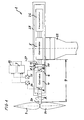
- FIG. 1 shows a schematic diagram of a stationary power generation plant 1 according to an embodiment of the invention.
- the power plant 1 converts mechanical energy of a rotor 3 via mechanical components and a generator into electrical energy, which is delivered by means of a frequency converter, for example to a load or a network.
- a rotor 3 In contrast to the rotor shown here has dimensions that make it necessary to arrange the power plant on a tower 22. In this case, the rotor 3 is exposed with its rotor blades 23 of the wind force, which sets a drive shaft 24 in the direction of arrow A in rotation.
- This rotation in a frequency spectrum of a few tenths of Hz to a few tens of Hz is translated via a transmission gear 4, which is arranged in a nacelle 25 together with a downstream generator 5 and a frequency converter 26, to a much higher rotational frequency.
- the transmission gear 4 can thereby achieve rotational frequencies of an output shaft 6 between tens of Hz and a few hundred Hz and thus drive the generator.
- the output shaft 6 can have a significantly smaller diameter and thus a lower area moment of inertia than the drive shaft 24.
- a braking device 2 can be dimensioned with a brake disk 10 on the output shaft 6 significantly smaller than when such a braking device in the drive shaft 24 is arranged.
- the transmission shafts and gears of the transmission gear 4 must be dimensioned accordingly to be able to transmit the forces acting on the brake disk 10 via the brake shoes 11 and 12 braking forces of the braking device 2. In doing so, a maximum permissible torsion element T zul for one of these shafts must not be exceeded.
- a control unit 7 which prescribes the braking force which acts on the brake shoes 11 and 12 and thus on the brake disk 10.
- This control unit 7 can have electronically stored a threshold value table, which has the threshold values with respect to the respective maximum permissible torsional moment of the individual components and shafts in the drive train 9 of this power generation plant 1.
- the torsional moment between the drive shaft 24 and the output shaft 6 is monitored by means of the sensors 8 and 18, which rises steeply at the onset of the braking process.
- the deceleration device 2 can be converted via the supply lines 27 by the control unit 7 to minimum load.
- a redundant controller 19, which cooperates with the sensors 8 and 18 and can supply the leads 27, is provided. If the control unit 7 fails, the redundant control unit 19 can provide emergency braking of the rotor 3.
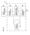
- FIG. 2 shows a scheme with function blocks 13 to 17 of the control unit 7 for a braking device 2 of the power generation plant 1 according to FIG. 1
- Block 13 supplies the sensor input signal to control unit 7.
- block 14 may consist of two control units, such as the FIG. 1 shows, exist and have a controller 7 and a redundant controller 19.
- the function block 16 outputs to the supply lines 27, the corresponding modulation of the braking force, wherein the control unit of the function block 14 via the function block 19 electrically or pneumatically causes this braking force modulation or via the function block 15, are provided in the controllable valves for inlet and outlet, the Modulation of the braking force in the function block 16 causes, so that these via the leads 27 to the in FIG. 1 shown braking device 2 can act.
- FIG. 3 shows a schematic diagram of a shutdown of a rotor of the power generation plant according to FIG. 1 ,
- the time t is plotted on the abscissa.
- an ordinate for the rotational speed n and a further ordinate for the torsional torque T are provided for this diagram.
- At time t 0 rotates the rotor of the power generation plant at a speed n, while the torsional moment the drive torque T A corresponds.
- This drive torque T A can be minimized by turning the rotary blades in a feathered position during an emergency shutdown.
- This period .DELTA.t can be determined from the forming torsional frequency by the mass moment of inertia, so that after the time interval .DELTA.t at time t 2, the braking device can be set to full load, between t 2 and t 3, the speed drops further, until finally again at t 3 the maximum permissible torsional moment T zul is reached and in turn the braking device is driven for a period .DELTA.t to minimum load until finally after the time interval .DELTA.t at time t 4, the braking device again on Full load is switched until at time t 5, the speed has dropped to zero and is maintained.
- This diagram shows that the speed curve with the speed n remains well below the aperiodic limit case and brings the rotor to a halt within the short time span of t 0 and t 5 , which can not be achieved with a gentle braking device.
Abstract
Description
Die Erfindung betrifft eine Energiegewinnungsanlage mit einer Abbremsvorrichtung. Die Energiegewinnungsanlage weist mindestens einen über ein Fluid angetriebenen Rotor und einen mit dem Rotor gekoppelten Generator auf. Die Abbremsvorrichtung ist auf einer Welle des Antriebsstranges angeordnet.The invention relates to an energy recovery system with a braking device. The energy recovery system has at least one rotor driven by a fluid and a generator coupled to the rotor. The braking device is arranged on a shaft of the drive train.
Aus der Druckschrift
Eine derartige Bremseinrichtung löst die Aufgabe zum Abbremsen eines Rotors einer Windenergieanlage, um eine leckagedichte Absperrung eines hydraulisch betätigbaren Bremszylinders zu gewährleisten. Dadurch soll eine sichere Bremsdruck- oder Bremslüftungsdruckmodulation mit hoher Genauigkeit möglich werden, so dass ein sanftes Abbremsen des Rotors sichergestellt ist.Such a braking device solves the task of braking a rotor of a wind turbine to ensure a leak-tight shut-off of a hydraulically actuated brake cylinder. As a result, a safe Bremsdruck- or brake release pressure modulation with high accuracy is possible, so that a smooth braking of the rotor is ensured.
Eine derartige Bremseinrichtung hat den Nachteil, dass sie Notsituationen, in denen ein Rotor einer Windkraftanlage in kürzest möglicher Zeit abzubremsen ist, nicht gerecht wird. Vielmehr wird durch das sanfte Abbremsen ein Abbremsvorgang vorgesehen, der theoretisch einem aperiodischen Grenzfall nahe kommt, da jedes Überschwingen unterdrückt wird, indem die Bremskraft so dosiert wird, dass ein steiler Drehmomentanstieg, wie es in Notsituationen zum Abbremsen eines . Rotors einer Windkraftanlage in kürzester Zeit erforderlich wäre, mit einer derartigen Bremseinrichtung nicht realisierbar ist.Such a braking device has the disadvantage that it emergency situations in which a rotor of a wind turbine is to be braked in the shortest possible time is not fair. Rather, the gentle deceleration is a deceleration process theoretically close to an aperiodic limit case, since any overshoot is suppressed by the braking force is metered so that a steep torque increase, as in emergency situations to decelerate a. Rotor of a wind turbine would be required in a very short time, with such a braking device is not feasible.
Um bei herkömmlichen Windkraftanlagen den Rotor in einer Notsituation abzubremsen, führt das Einfallen der Bremse aufgrund der rotierenden hohen Massen zu einem Drehmomentanstieg im Antriebsstrang, der das statische Bremsmoment überschreitet. Um diese Spitzen der Torsionsmomente beim Abbremsen eines Rotors in einer Notsituation durch den Antriebsstrang aufnehmen zu können, müssen die im Leistungsfluss liegenden Komponenten des Antriebsstranges der Energiegewinnungsanlage entsprechend überdimensioniert werden, so dass derartige Spitzendrehmomente nicht zur Beschädigung der Energiegewinnungsanlage führen. Aufgrund der bei einer derartigen Notabbremsung auftretenden Torsionsschwingungen wird bei herkömmlichen Energiegewinnungsanlagen das Übersetzungsgetriebe auf das drei- bis vierfache der Betriebsbelastung ausgelegt, was bei Windkraftanlagen nachteilig zu erheblichen Gewichten in der Generatorgondel führt.To decelerate the rotor in an emergency situation in conventional wind turbines, the collapse of the brake due to the rotating high masses leads to an increase in torque in the drive train, which exceeds the static braking torque. In order to absorb these peaks of torsional moments when braking a rotor in an emergency situation by the drive train, lying in the power flow components of the drive train of the power plant must be over-dimensioned accordingly, so that such peak torques do not lead to damage to the power plant. Due to the torsional vibrations occurring in such a Notabbremsung the transmission gear is designed to three to four times the operating load in conventional power plants, resulting in wind turbines disadvantageous leads to significant weights in the generator nacelle.
Die
Aufgabe der Erfindung ist es, eine stationäre Energiegewinnungsanlage mit einer Abbremsvorrichtung zu schaffen, die bei deutlich vermindertem Gewicht der Komponenten des Antriebsstranges eine sichere und kurzzeitige Notabschaltung des Rotors ermöglicht.The object of the invention is to provide a stationary power generation plant with a braking device, which allows for a significantly reduced weight of the components of the drive train a safe and short-term emergency shutdown of the rotor.
Diese Aufgabe wird mit dem Gegenstand des unabhängigen Anspruchs 1 gelöst. Vorteilhafte Weiterbildungen ergeben sich aus den abhängigen Ansprüchen.This object is achieved with the subject matter of independent claim 1. Advantageous developments emerge from the dependent claims.
Erfindungsgemäß wird eine stationäre Energiegewinnungsanlage mit einer Abbremsvorrichtung geschaffen. Die Energiegewinnungsanlage weist mindestens einen aerodynamisch angetriebenen Rotor und einen mit dem Rotor gekoppelten Generator auf. Die Abbremsvorrichtung ist auf einer Welle des Antriebsstranges angeordnet. Die Abbremsvorrichtung wirkt mit einem Steuergerät zusammen, wobei bei Annäherung an einen vorgegebenen Torsionsschwellwert das Steuergerät die Abbremskraft der Abbremsvorrichtung verringert.According to the invention, a stationary power generation plant with a braking device is provided. The power generation plant has at least one aerodynamically driven rotor and a generator coupled to the rotor. The braking device is on a shaft of the Drivetrain arranged. The deceleration device cooperates with a control device, wherein the control device reduces the deceleration force of the deceleration device when approaching a predetermined torsional threshold value.
Diese Lösung hat den Vorteil, dass die Abbremsvorrichtung mit Volllast auf den Abtriebsstrang einwirken kann. Da eine derartige Energiegewinnungsanlage ein schwingungsfähiges Gebilde ist, führt dieser Einsatz der Abbremsvorrichtung mit Volllast, d.h. mit höchstmöglicher Bremsstärke und höchstmöglichem Bremsmoment, zu einem steilen Anstieg der Torsionsmomente in den Wellen des Antriebsstranges. Um dennoch ein Überschwingen über das zulässige maximale Torsionsmoment einer kritischen Welle des Antriebsstranges zu vermeiden, wird ein Überschwingen des Momentes überwacht und im Fall der Annäherung an den vorgegebenen Torsionsschwellwert die Bremskraft kurz vor Erreichen des Überschwingzustands auf eine Minimallast der Rotorbremsvorrichtung vermindert. Da sich für diesen Fall die ausbildende Torsionseigenfrequenz durch das Massenträgheitsmoment und die Steifigkeit des Antriebsstranges vom Rotor bis zur Abbremsvorrichtung bestimmt, lässt sich daraus auch die Zeitspanne Δt bestimmen, nach der die Abbremsvorrichtung wieder mit Volllast gefahren werden kann.This solution has the advantage that the braking device can act on the output train with full load. Since such a power plant is a vibratory structure, this use of the braking device at full load, i. with the highest possible braking power and the highest possible braking torque, to a steep increase in the torsional moments in the shafts of the drive train. In order nevertheless to avoid overshooting the permissible maximum torsional moment of a critical shaft of the drive train, an overshoot of the torque is monitored and in the case of approaching the predetermined Torsionsschwellwert the braking force is reduced shortly before reaching the overshoot to a minimum load of the rotor brake device. Since, in this case, the forming torsional natural frequency is determined by the mass moment of inertia and the rigidity of the drive train from the rotor to the braking device, it is also possible to determine the time span Δt after which the braking device can be driven again at full load.
Dazu wertet das Steuergerät Signale von mindestens einem Sensorelement zur Torsionsmomenterfassung einer kritischen Welle des Antriebsstranges aus. Dabei wird das Bremsmoment der Abbremsvorrichtung vermindert, wenn der vorgegebene Torsionsschwellenwert in Bezug auf ein zulässiges Torsionsmoment einer kritischen Welle des Antriebsstranges erreicht wird.For this purpose, the control unit evaluates signals from at least one sensor element for torsional moment detection of a critical shaft of the drive train. In this case, the braking torque of the braking device is reduced when the predetermined Torsionsschwellenwert is achieved with respect to a permissible torsional moment of a critical shaft of the drive train.
Im Gegensatz zu der aus dem Stand der Technik bekannten sanften Abbremsmethode wird hier über das eingesetzte Steuergerät die Möglichkeit gegeben, deutlich kurzfristiger den Rotor einer Energiegewinnungsanlage in einer Notsituation zum Stehen zu bringen. Dazu kann die Abbremsvorrichtung eine auf der Abtriebswelle eines Übersetzungsgetriebes angeordnete Bremsscheibe aufweisen, die mit Bremsbacken zusammenwirkt, deren Bremskraft durch den Schwellwert in Bezug auf das zulässige Torsionsmoment Tzul mindestens der Abtriebswelle des Übersetzungsgetriebes begrenzt ist. Grundsätzlich ist es jedoch auch möglich, eine der Übersetzungswellen des Übersetzungsgetriebes oder auch die Antriebswelle selbst derart zu dimensionieren, dass diese maßgebend für den Schwellwert des zulässigen Torsionsmomentes Tzul wird.In contrast to the well-known from the prior art gentle deceleration method is given here on the controller used the opportunity to bring the rotor of an energy production plant in an emergency situation to a much shorter time. For this purpose, the braking device may have a disposed on the output shaft of a transmission gear brake disc, which cooperates with brake shoes whose braking force by the threshold value with respect to the allowable torsional moment T zul at least the output shaft of the Transmission is limited. In principle, however, it is also possible to dimension one of the transmission shafts of the transmission gear or the drive shaft itself such that it is authoritative for the threshold value of the permissible torsional moment T zul .
Vorzugsweise ist die stationäre Energiegewinnungsanlage eine Windenergieanlage, die auch WEA- bzw. WKA (Windkraftanlage) genannt und mit den
Vorzugsweise ist vor dem Erreichen des Schwellwertes in Bezug auf das zulässige Torsionsmoment Tzul der kritischen Welle die Bremskraft der Abbremsvorrichtung auf Volllast oberhalb des aperiodischen Grenzfalls gestellt und bei Erreichen des Schwellwertes ist die Bremskraft auf Minimallast heruntergefahren. Eine Bremskraft vorzusehen, die bei Volllast oberhalb des aperiodischen Grenzfalls eingestellt ist, hat den Vorteil, dass ein deutlich steilerer Abfall der Drehzahl des Rotors erreicht werden kann, als es bei einem aperiodischen Grenzfall oder bei einer aus dem Stand der Technik bekannten sanften Abbremsung erreichbar ist.Preferably, before reaching the threshold value with respect to the permissible torsional moment T zul of the critical shaft, the braking force of the braking device is set to full load above the aperiodic limit, and when the threshold value is reached, the braking force is reduced to minimum load. To provide a braking force that is set at full load above the aperiodic limit case, has the advantage that a much steeper drop in the speed of the rotor can be achieved, as it is achievable in a aperiodic limit case or in a known from the prior art gentle deceleration ,
Vorzugsweise weist die Energiegewinnungsanlage mehrere Sensorelemente zur Torsionsmomentenerfassung unterschiedlicher Wellen des Antriebsstranges auf. Wie bereits oben erwähnt, kann sich der Schwellwert für die Bremskraft nicht nur auf die Abtriebswelle des Übersetzungsgetriebes beziehen, auf dem die Bremsscheibe der Abbremsvorrichtung angeordnet ist, sondern auch auf eine der anderen Wellen, die beispielsweise als Übersetzungswellen im Übersetzungsgetriebe angeordnet sind oder als Antriebswelle zwischen Rotor und Getriebe dienen. In solchen Fällen sind die Sensorelemente zur Erfassung des Torsionsmomentes an diesen Wellen zu positionieren oder es ist ein entsprechendes Modell im Steuergerät zu speichern, das aus der Torsionsmomentendifferenz zwischen Antriebswelle und Abtriebswelle für das Getriebe auf den Zustand bzw. die Torsionsbelastung der übrigen Wellen schließen lässt. Dazu kann das Steuergerät eine Wertetabelle aufweisen, welche die zulässigen Torsionsmomente Tzul der Wellen des Antriebsstranges von dem Rotor bis zur Abtriebswelle des Übersetzungsgetriebes aufweist.Preferably, the energy recovery system has a plurality of sensor elements for Torsionsmomentenerfassung different waves of the drive train. As already mentioned above, the threshold value for the braking force can relate not only to the output shaft of the transmission gear on which the brake disc of the braking device is arranged, but also to one of the other shafts, which are arranged for example as transmission shafts in the transmission gear or drive shaft between Serve rotor and gear. In such cases, the sensor elements for detecting the torsional moment to be positioned on these waves or it is to store a corresponding model in the control unit, which can conclude from the torsional moment difference between the drive shaft and output shaft for the transmission to the state or the torsional load of the other waves. For this purpose, the control unit may have a value table which shows the permissible torsional moments T zul of the waves of the Drive train from the rotor to the output shaft of the transmission has.
Zur Steuerung der Bremskraft kann die Abbremsvorrichtung hydraulische Steuerventile aufweisen, wie sie bereits aus dem Stand der Technik gemäß
Die Steuereinheit kann separat als Zusatzgerät oder Nachrüstsatz für eine Energiegewinnungsanlage vorgesehen werden oder in einer zentralen Steuereinheit der stationären Energiegewinnungsanlage integriert sein. Da eine zentrale Steuereinheit über eine Vielzahl von Sensoren und Sensorsignalen, insbesondere zur Höhe der Torsionsbelastungen, in dem Antriebsstrang verfügt, kann in einem solchen Fall auf separate Sensoren für die Abbremsvorrichtung verzichtet werden.The control unit can be provided separately as an accessory or retrofit kit for an energy recovery system or integrated in a central control unit of the stationary power generation plant. Since a central control unit has a large number of sensors and sensor signals, in particular the magnitude of the torsional loads, in the drive train, separate sensors for the braking device can be dispensed with in such a case.
In eine Ausführungsform ist das Steuergerät zum Einstellen der Bremskraft in Abhängigkeit eines vorgegebenen Zeitprogramms eingerichtet. Damit ist es auch möglich, die Bremseinrichtung in sensorlos und gesteuert zu betreiben. Weil die Torsionseigenfrequenz des Antriebsstrangs in vielen Windenergieanlagen bekannt sind, lässt sich der Bremsvorgang auch ohne Sensor hinreichend genau zeitlich steuern.In one embodiment, the control unit is set up for setting the braking force as a function of a predetermined time program. Thus, it is also possible to operate the brake device in sensorless and controlled. Because the torsional natural frequency of the powertrain is known in many wind turbines, the braking process can be timed with sufficient accuracy even without a sensor.
In einer Ausführungsform ist das Steuergerät zum Variieren des Zeitprogramm in Abhängigkeit der Drehzahl des Rotors eingerichtet ist. Dies bedeutet, dass bei unterschiedlichen Drehzahlen unterschiedliche Zeitprogramme abgefahren werden.In one embodiment, the control unit is configured to vary the time program as a function of the rotational speed of the rotor. This means that different time programs are run at different speeds.
Ebenso wird in einer anderen Ausführung das Steuergerät zum Variieren des Zeitprogramms in Abhängigkeit der Windlast eingerichtet.Likewise, in another embodiment, the control unit is set up to vary the time program as a function of the wind load.
Ein Verfahren zur Schnellabbremsung eines Rotors einer Energiegewinnungsanlage weist die nachfolgenden Verfahrensschritte auf. Zunächst werden die zulässigen Trägheitsmomente in einem Antriebsstrang einer Energiegewinnungsanlage von einem Rotor über ein Übersetzungsgetriebe bis zu der Abbremsvorrichtung ermittelt. Daraus wird eine kritische Welle in dem Antriebsstrang zwischen Rotor und Abbremsvorrichtung definiert. Ein Sensorelement wird derart angeordnet, dass mindestens das Torsionsmoment der kritischen Welle beim Abbremsen erfasst und überwacht wird.A method for rapid deceleration of a rotor of an energy production plant has the following method steps. First, the allowable moments of inertia are determined in a drive train of an energy recovery system of a rotor via a transmission gear to the deceleration device. This defines a critical shaft in the drive train between the rotor and the braking device. A sensor element is arranged such that at least the torsional moment of the critical shaft is detected and monitored during deceleration.
Unter diesen Voraussetzungen kann nun ein Anfahren der Abbremsvorrichtung mit Volllast erfolgen, wobei diese Volllast höher als die Bremskraft beim aperiodischen Grenzfall ist, bis ein Überschwingen bevorsteht. Dann wird die Abbremsvorrichtung auf Minimallast gesteuert, sobald ein Schwellwert in Bezug auf ein zulässige Torsionsmoment Tzul der kritischen Welle erreicht ist. Schließlich wird dieser Minimalwert beibehalten, bis unter Berücksichtigung von Masseträgheitsmoment und Steifigkeit des Antriebsstranges zwischen Rotor und Abbremsvorrichtung ein erneuter Volllastbetrieb der Abbremsvorrichtung zulässig ist.Under these conditions, a start of the braking device can now be carried out at full load, this full load is higher than the braking force in the aperiodic limit case until an overshoot is imminent. Then, the deceleration device is controlled to minimum load as soon as a threshold value is reached with respect to an allowable torsional moment T zul of the critical shaft. Finally, this minimum value is maintained until, taking into account the mass moment of inertia and stiffness of the drive train between the rotor and the braking device, a renewed full-load operation of the braking device is permitted.
Dieses Verfahren hat den Vorteil, dass in deutlich kürzeren Zeitabständen ein Abbremsen des Rotors möglich wird, selbst wenn die Komponenten in dem Antriebsstrang in ihrer Steifigkeit und ihrem Masseträgheitsmoment deutlich reduziert sind. Dieses hat den weiteren Vorteil, dass eine hohe Gewichtseinsparung für beispielsweise das Übersetzungsgetriebe und eventuell auch für die Antriebs- und die Abtriebswelle des Übersetzungsgetriebes möglich wird.This method has the advantage that braking of the rotor becomes possible at significantly shorter time intervals, even if the components in the drive train are significantly reduced in their rigidity and their mass moment of inertia. This has the further advantage that a high weight saving for example, the transmission gear and possibly also for the drive and the output shaft of the transmission is possible.
Zur Steuerung der Bremskraft kann ein hydraulisches oder pneumatisches oder elektromechanisches System eingesetzt werden. Ferner ist bei dem Verfahren vorgesehen, die Bremskraft der Abbremsvorrichtung mindestens an den Schwellwert in Bezug auf das zulässige Torsionsmoment Tzul der Abtriebswelle des Übersetzungsgetriebes anzupassen. Auch können mehrere Wellen der Energiegewinnungsanlage mittels mehrerer Sensorelemente zur Torsionsmomentenerfassung des Antriebsstranges überwacht werden.To control the braking force, a hydraulic or pneumatic or electromechanical system can be used. Furthermore, it is provided in the method, the braking force of the braking device at least to the threshold value to adjust with respect to the allowable torsional moment T zul the output shaft of the transmission gear. Also, several waves of the power plant can be monitored by means of several sensor elements for Torsionsmomentenerfassung the drive train.
Vorzugsweise wird bei Erreichen eines der Schwellwerte aus einer in dem Steuergerät gespeicherten Wertetabelle, welche die zulässigen Torsionsmomente Tzul der Wellen des Antriebsstranges von dem Rotor bis zur Abtriebswelle des Übersetzungsgetriebes speichert, das Steuergerät die Volllast der Abbremsvorrichtung auf Minimallast reduzieren. Außerdem ist für eine bevorzugte Durchführungsform des Verfahrens vorgesehen, dass vor dem Erreichen des Schwellwertes in Bezug auf das zulässige Torsionsmoment Tzul der kritischen Welle die Bremskraft der Abbremsvorrichtung auf Volllast oberhalb des aperiodischen Grenzfalls eingestellt wird und erst bei Erreichen des Schwellwertes die Bremskraft auf Minimallast umgestellt wird.Preferably, upon reaching one of the threshold values from a value table stored in the control unit, which stores the permissible torsional torques T zul of the drive train from the rotor to the output shaft of the transmission, the control unit reduces the full load of the braking device to a minimum load. In addition, it is provided for a preferred implementation of the method that before reaching the threshold value with respect to the permissible torsional torque T perm of the critical shaft, the braking force of the braking device is set to full load above the aperiodic limit case and only when the threshold value is reached, the braking force to minimum load becomes.
Die Erfindung wird nun anhand der nachfolgenden Figuren näher erläutert.
- Figur 1
- zeigt eine Prinzipskizze einer stationären Energiegewinnungsanlage gemäß einer Ausführungsform der Erfindung;
- Figur 2
- zeigt ein Schema mit Funktionsblöcken eines Steuergeräts für eine Abbremsvorrichtung der Energiegewinnungsanlage gemäß
Figur 1 ; - Figur 3
- zeigt ein schematisches Diagramm einer Abschaltung eines Rotors der Energiegewinnungsanlage gemäß
Figur 1 .
- FIG. 1
- shows a schematic diagram of a stationary power generation plant according to an embodiment of the invention;
- FIG. 2
- shows a diagram with function blocks of a controller for a braking device of the power generation plant according to
FIG. 1 ; - FIG. 3
- shows a schematic diagram of a shutdown of a rotor of the power generation plant according to
FIG. 1 ,
Diese Rotation in einem Frequenzspektrum von einigen Zehntel Hz bis einigen Zehn Hz wird über ein Übersetzungsgetriebe 4, das in einer Gondel 25 zusammen mit einem nachgeschalteten Generator 5 und einem Frequenzumrichter 26 angeordnet ist, auf eine deutlich höhere Rotationsfrequenz übersetzt. Das Übersetzungsgetriebe 4 kann dabei Rotationsfrequenzen einer Abtriebswelle 6 zwischen einigen Zehn Hz und einigen Hundert Hz erreichen und damit den Generator antreiben. In Folge dieser Übersetzung kann die Abtriebswelle 6 einen deutlich geringeren Durchmesser und damit ein geringeres Flächenträgheitsmoment aufweisen als die Antriebswelle 24. Ferner kann eine Abbremsvorrichtung 2 mit einer Bremsscheibe 10 auf der Abtriebswelle 6 deutlich kleiner dimensioniert werden, als wenn eine derartige Abbremsvorrichtung im Bereich der Antriebswelle 24 angeordnet ist. Die Übersetzungswellen und Zahnräder des Übersetzungsgetriebes 4 müssen jedoch entsprechend dimensioniert werden, um die auf die Bremsscheibe 10 über die Bremsbacken 11 und 12 einwirkenden Bremskräfte der Abbremsvorrichtung 2 übertragen zu können. Dabei darf ein maximal zulässiges Torsionselement Tzul für eine dieser Wellen nicht überschritten werden.This rotation in a frequency spectrum of a few tenths of Hz to a few tens of Hz is translated via a
Um eine kurzzeitige Notabbremsung für den Rotor 3 zu gewährleisten, ist ein Steuergerät 7 vorgesehen, das die Bremskraft, welche auf die Bremsbacken 11 und 12 und damit auf die Bremsscheibe 10 wirkt, vorgibt. Dieses Steuergerät 7 kann elektronisch gespeichert eine Schwellwerttabelle aufweisen, welche die Schwellwerte in Bezug auf das jeweils maximal zulässige Torsionsmoment der einzelnen Komponenten und Wellen im Antriebsstrang 9 dieser Energiegewinnungsanlage 1 aufweist. Beim Einsetzen der Abbremsvorrichtung 2 durch das Steuergerät 7 wird zunächst, um ein kurzzeitiges Abbremsen zu erreichen, mit einem höchstmöglichen Bremsmoment gearbeitet, das über pneumatische, hydraulische oder elektrische Zuleitungen 27 von dem Steuergerät 7 aus eingestellt wird.In order to ensure a brief emergency braking for the rotor 3, a control unit 7 is provided which prescribes the braking force which acts on the
Gleichzeitig wird mit Hilfe der Sensoren 8 und 18 das Torsionsmoment zwischen Antriebswelle 24 und Abtriebswelle 6 überwacht, das beim Einsetzen des Bremsvorganges steil ansteigt. Vor Erreichen eines Überschwingfalles, der durch die Sensoren 8 und 18 mit Hilfe der Signalwandler 20 und 21 erfasst wird, kann die Abbremsvorrichtung 2 über die Zuleitungen 27 durch das Steuergerät 7 auf Minimallast umgestellt werden. Aus Sicherheitsgründen ist es in dieser Ausführungsform der Erfindung vorgesehen, ein redundantes Steuergerät 19, das mit den Sensoren 8 und 18 zusammenwirkt und die Zuleitungen 27 versorgen kann, vorgesehen. Sollte das Steuergerät 7 ausfallen, so kann das redundante Steuergerät 19 für eine Notbremsung des Rotors 3 sorgen.At the same time, the torsional moment between the
Wird ein sanftes Abschalten bzw. Abbremsen durchgeführt, das jegliches Überschwingen vermeidet, so ergibt sich ein relativ langer Zeitraum bis das maximal zulässige Torsionsmoment Tzul während eines so genannten aperiodischen Grenzfalles erreicht wird, wobei gleichzeitig ein erhebliches Zeitintervall erforderlich ist, um die Rotorblätter zum Stehen zu bringen, wie es die Kurve für die aperiodische Drehzahl nap zeigt. Um schneller und deutlich kürzer in einer Notabschaltung den Rotor zum Stehen zu bringen, wird bei den herkömmlichen Anlagen ein Überschwingen der schwingungsfähigen Energiegewinnungsanlage in Kauf genommen. Dann muss jedoch auch diese Anlage die Torsionsspitzen T1, T2 und T3 schadlos überstehen, die sich bei derartigen Schnellabschaltungen einer schwingungsfähigen Energiegewinnungsanlage aufbauen können.If a smooth shutdown or deceleration is performed, which avoids any overshoot, then there is a relatively long period until the maximum allowable torsional moment T zul is achieved during a so-called aperiodic limit case, at the same time a considerable time interval is required to the rotor blades to a standstill to bring, as it shows the curve for the aperiodic speed n ap . In order to bring the rotor to a standstill faster and significantly shorter in an emergency shutdown, in the conventional systems an overshoot of the oscillatory power generation plant is accepted. Then, however, this system must withstand the torsion peaks T 1 , T 2 and T 3 without damage, which can build up in such rapid shutdowns of a vibratory power generation plant.
Um ein kurzfristiges Abschalten zwischen t0 und t5 zu erreichen, wobei die Drehzahl von einer Anfangsdrehzahl n0 auf eine Enddrehzahl ne = 0 des Rotors abfällt, wird die erfindungsgemäße Abbremsvorrichtung zunächst mit Volllast angefahren, so dass im Zeitpunkt t1 das maximal zulässige Torsionsmoment Tzul einer kritischen Welle im Antriebsstrang erreicht wird. In diesem Augenblick t1 wird durch das Steuergerät die Abbremsvorrichtung für eine Zeitspanne Δt beispielsweise durch Öffnen der Bremse auf Minimallast gefahren.In order to achieve a short-term shutdown between t 0 and t 5 , wherein the speed drops from an initial speed n 0 to a final speed n e = 0 of the rotor, the braking device according to the invention is first approached at full load, so that at time t 1, the maximum allowable Torsion torque T perm of a critical shaft in the drive train is achieved. At this moment t 1 , the braking device is driven by the control unit for a period Δt, for example by opening the brake to minimum load.
Diese Zeitspanne Δt lässt sich aus der sich ausbildenden Torsionsfrequenz durch das Massenträgheitsmoment bestimmen, so dass nach dem Zeitintervall Δt zum Zeitpunkt t2 die Abbremsvorrichtung wieder auf Volllast gestellt werden kann, wobei zwischen t2 und t3 die Drehzahl weiter absinkt, bis schließlich erneut bei t3 das maximal zulässige Torsionsmoment Tzul erreicht ist und wiederum die Abbremsvorrichtung für einen Zeitraum Δt auf Minimallast gefahren wird, bis schließlich nach dem Zeitintervall Δt beim Zeitpunkt t4 die Abbremsvorrichtung erneut auf Volllast geschaltet wird, bis im Zeitpunkt t5 die Drehzahl auf Null abgesunken ist und beibehalten bleibt.This period .DELTA.t can be determined from the forming torsional frequency by the mass moment of inertia, so that after the time interval .DELTA.t at time t 2, the braking device can be set to full load, between t 2 and t 3, the speed drops further, until finally again at t 3 the maximum permissible torsional moment T zul is reached and in turn the braking device is driven for a period .DELTA.t to minimum load until finally after the time interval .DELTA.t at time t 4, the braking device again on Full load is switched until at time t 5, the speed has dropped to zero and is maintained.
Dieses Diagramm zeigt, dass die Drehzahlkurve mit der Drehzahl n deutlich unter dem aperiodischen Grenzfall bleibt und innerhalb der kurzen Zeitspanne von t0 und t5 den Rotor zum Stehen bringt, was mit einer sanften Abbremsvorrichtung nicht erreichbar ist.This diagram shows that the speed curve with the speed n remains well below the aperiodic limit case and brings the rotor to a halt within the short time span of t 0 and t 5 , which can not be achieved with a gentle braking device.
- 11
- EnergiegewinnungsanlageEnergy recovery plant
- 22
- Abbremsvorrichtungbraking device
- 33
- Rotorrotor
- 44
- Übersetzungsgetriebeup gear
- 55
- Generatorgenerator
- 66
- Abtriebswelleoutput shaft
- 77
- Steuergerätcontrol unit
- 88th
- Sensorelementsensor element
- 99
- Antriebsstrangpowertrain
- 1010
- Bremsscheibebrake disc
- 1111
- Bremsbackebrake shoe
- 1212
- Bremsbackebrake shoe
- 1313
- Funktionsblockfunction block
- 1414
- Funktionsblockfunction block
- 1515
- Funktionsblockfunction block
- 1616
- Funktionsblockfunction block
- 1717
- Funktionsblockfunction block
- 1818
- Sensorelementsensor element
- 1919
- redundantes Steuergerätredundant controller
- 2020
- Signalwandler bzw. SignalverstärkerSignal converter or signal amplifier
- 2121
- Signalwandler bzw. SignalverstärkerSignal converter or signal amplifier
- 2222
- Turmtower
- 2323
- Rotorblattrotor blade
- 2424
- Antriebswelledrive shaft
- 2525
- Gondelgondola
- 2626
- Frequenzumrichterfrequency converter
- 2727
- Zuleitungsupply
- AA
- Pfeilrichtungarrow
- Tzul T perm
- maximal zulässiges Torsionsmomentmaximum permissible torsional moment
- TB T B
- Bremsmomentbraking torque
- Δt.delta.t
- Zeitspanne der MinimallastTime span of the minimum load
- tt
- ZeitTime
Claims (18)
- Stationary energy production plant having a braking device (2), wherein the energy production plant (1) has the rotor (3) which is driven by means of a fluid and a generator (5) which is coupled to the rotor, and wherein the braking device (2) is arranged on a shaft of the drive train (9) and interacts with a control device (7), wherein, when a torsion threshold value is approached, the control device (7) reduces the braking force of the braking device (2),
characterized
in that the control device evaluates signals of at least one sensor element (8) for sensing the torsion torque of a critical shaft of the drive train (9), wherein a threshold value is predefined with respect to a permissible torsion torque (Tperm) of the critical shaft for the braking torque (TB) of the braking device (2). - Energy production plant according to Claim 1,
characterized
in that the braking device (2) has a brake disc (10) which is arranged on the output shaft (6) of a speed reduction gearbox (4) and which interacts with brake callipers (11, 12) whose braking force is limited by the threshold value with respect to the permissible torsion torque (Tperm) at least of the output shaft (6) of the speed reduction gearbox (4). - Energy production plant according to Claim 2,
characterized
in that, before the threshold value for the permissible torsion torque (Tperm) of the critical shaft is reached, the braking force of the braking device (2) is set to full load above the aperiodic limiting case (Tap), and when the threshold value is reached the braking force is set to a minimum load. - Energy production plant according to one of Claims 1 to 3,
characterized
in that the energy production plant (1) has a plurality of sensor elements (8, 18) for detecting the torsion torque of the drive train (9). - Energy production plant according to one of the preceding claims, characterized in that the control device (7) has a value table which has the permissible torsion torques (Tperm) of the shafts of the drive train (9) from the rotor (3) to the output shaft (6) of the speed reduction gearbox (4).
- Energy production plant according to one of the preceding claims,
characterized
in that the time period Δt for the application of a minimum load in the brake system is determined by the moment of mass inertia and the rigidity of the drive train (9) from the rotor (3) to the braking device (2) by the torsion frequency which is formed. - Energy production plant according to one of the preceding claims,
characterized
in that the braking device (2) has hydraulic control valves for controlling the braking force. - Energy production plant according to one of the preceding claims,
characterized
in that the braking device (2) has pneumatic control valves for controlling the braking force. - Energy production plant according to one of the preceding claims,
characterized
in that the braking device (2) has electromechanical actuator elements for controlling the braking force. - Energy production plant according to one of the preceding claims,
characterized in that
the control device is configured to set the braking force as a function of a predefined time programme. - Energy production plant according to Claim 10,
characterized in that
the control device is configured to vary the time programme as a function of the rotational speed of the rotor. - Energy production plant according to Claim 10,
characterized in that
the control device is configured to vary the time programme as a function of the wind load. - Method for rapid braking of an energy production plant (1), wherein- the permissible moments of inertia of the shafts in a drive train (9) of an energy production plant (1) from a rotor (3) to the braking device (2) are determined;- a critical shaft in the drive train (9) between the rotor (3) and the braking device (2) is defined;- a sensor element (8) is arranged in such a way that at least the torsion torque (Tperm) of the critical shaft is sensed during braking;- the braking device (2) is started with full load, which is higher than the braking force in the aperiodic limiting case, until harmonics are imminent, and- the braking device (2) is adjusted to minimum load as soon as a threshold value for a permissible torsion torque of the critical shaft is reached, and- the minimum load is maintained until a full load operating mode of the braking device (2) is permitted again taking into account the moment of mass inertia and the rigidity of the drive train between the rotor (3) and the braking device (2).
- Method according to Claim 13,
characterized
in that the braking force is controlled by means of a hydraulic or pneumatic or electromechanical system. - Method according to Claim 13 or Claim 14,
characterized
in that the braking force of the braking device (2) is adapted at least to the threshold value for the permissible torsion torque (Tperm) of the output shaft (6) of a speed reduction gearbox (4). - Method according to Claim 15,
characterized
in that a plurality of shafts of the energy production plant (1) are monitored by means of a plurality of sensor elements (8, 18) for sensing the torsion torque of the drive train (9). - Method according to Claim 16,
characterized
in that, when one of the threshold values from the value table which stores the permissible torsion torque (Tperm) of the shafts of the drive train (9) from the rotor (3) to the output shaft (6) of the speed reduction gearbox (4) is reached, the control device (7) adjusts the full load of the braking device (2) to minimum load. - Method according to one of Claims 13 to 17,
characterized in that
before the threshold value for the permissible torsion torque (Tperm) of the critical shaft is reached, the braking force of the braking device (2) is set to full load above the aperiodic limiting case (Tap), and the braking force is not adjusted to minimum load until the threshold value is reached.
Applications Claiming Priority (2)
| Application Number | Priority Date | Filing Date | Title |
|---|---|---|---|
| DE102009006054A DE102009006054A1 (en) | 2009-01-24 | 2009-01-24 | Stationary power generation plant with a deceleration device |
| PCT/EP2009/009164 WO2010083866A2 (en) | 2009-01-24 | 2009-12-19 | Stationary energy production plant having a braking device |
Publications (2)
| Publication Number | Publication Date |
|---|---|
| EP2389509A2 EP2389509A2 (en) | 2011-11-30 |
| EP2389509B1 true EP2389509B1 (en) | 2012-08-22 |
Family
ID=42282582
Family Applications (1)
| Application Number | Title | Priority Date | Filing Date |
|---|---|---|---|
| EP09801411A Not-in-force EP2389509B1 (en) | 2009-01-24 | 2009-12-19 | Stationary energy production plant having a braking device |
Country Status (5)
| Country | Link |
|---|---|
| EP (1) | EP2389509B1 (en) |
| DE (1) | DE102009006054A1 (en) |
| DK (1) | DK2389509T3 (en) |
| ES (1) | ES2390259T3 (en) |
| WO (1) | WO2010083866A2 (en) |
Families Citing this family (6)
| Publication number | Priority date | Publication date | Assignee | Title |
|---|---|---|---|---|
| US8047770B2 (en) * | 2009-12-30 | 2011-11-01 | General Electric Company | Methods and systems for providing variable mechanical brake torque |
| ES2400884B1 (en) * | 2011-01-03 | 2014-03-18 | Acciona Windpower, S.A. | OSCILLATION REDUCTION METHOD IN AN AIRBRUSHER |
| EP2479427A1 (en) * | 2011-01-24 | 2012-07-25 | Siemens Aktiengesellschaft | Method for attenuating the oscillation of a power train in a wind turbine, wind turbine and use of a braking device |
| US10340839B2 (en) | 2015-12-22 | 2019-07-02 | Solarcity Corporation | Dynamic damping system for solar trackers |
| US10340840B2 (en) | 2015-12-28 | 2019-07-02 | Solarcity Corporation | Oscillation brake for solar tracking system |
| DE102016013796A1 (en) * | 2016-11-21 | 2018-05-24 | Senvion Gmbh | Wind turbine with braking device and method for operating the same |
Family Cites Families (5)
| Publication number | Priority date | Publication date | Assignee | Title |
|---|---|---|---|---|
| GB8716506D0 (en) * | 1987-07-14 | 1987-08-19 | Lawson Tancred Sons & Co Ltd S | Wind turbine operating system |
| US6254197B1 (en) * | 1996-11-22 | 2001-07-03 | Svendborg Brakes A/S | Hydraulic braking system |
| DE10153798C2 (en) * | 2001-11-05 | 2003-07-31 | Norbert Hennchen | Method and device for decelerating a rotor of a wind turbine |
| US7451990B2 (en) | 2004-04-29 | 2008-11-18 | Jacobs Chuck Manufacturing Company | Chuck with torque indicator |
| DE102004057739A1 (en) | 2004-10-08 | 2006-04-13 | Bosch Rexroth Ag | Brake unit for braking of rotor of wind power plant has block valve designed as directional seating valve installed in pressure medium path between tank connection of directional valve and pressure medium sink |
-
2009
- 2009-01-24 DE DE102009006054A patent/DE102009006054A1/en not_active Withdrawn
- 2009-12-19 DK DK09801411.1T patent/DK2389509T3/en active
- 2009-12-19 WO PCT/EP2009/009164 patent/WO2010083866A2/en active Application Filing
- 2009-12-19 ES ES09801411T patent/ES2390259T3/en active Active
- 2009-12-19 EP EP09801411A patent/EP2389509B1/en not_active Not-in-force
Also Published As
| Publication number | Publication date |
|---|---|
| DE102009006054A1 (en) | 2010-07-29 |
| ES2390259T3 (en) | 2012-11-08 |
| DK2389509T3 (en) | 2012-11-12 |
| EP2389509A2 (en) | 2011-11-30 |
| WO2010083866A3 (en) | 2011-04-21 |
| WO2010083866A2 (en) | 2010-07-29 |
Similar Documents
| Publication | Publication Date | Title |
|---|---|---|
| EP2389509B1 (en) | Stationary energy production plant having a braking device | |
| EP2479428B1 (en) | Wind turbine with a brake device and method for braking as well as use of the brake device | |
| EP1286049B1 (en) | Wind turbine | |
| DE102006029640B4 (en) | Wind turbine with a machine house | |
| EP3152437B1 (en) | Vertical axis wind turbine and method for operating of such a turbine | |
| EP2929176B1 (en) | Turn drive for a wind turbine and method for rotating the rotor shaft of a wind turbine | |
| EP2058513B1 (en) | Method for operating a wind farm | |
| EP2396542A2 (en) | Brake system for a wind turbine | |
| EP1910670A1 (en) | Wind power plant comprising individual pitch devices | |
| EP2101058A2 (en) | Method and device for turning a component of a wind energy plant | |
| EP1622800B1 (en) | Braking device for a wind power plant comprising a rotor, which converts wind energy into rotational motion, and method for operating a braking device of this type | |
| DE102007040834A1 (en) | Wind energy plant operating method, involves changing operating parameter of wind energy plant corresponding to change in load, and operating brake system for changing operating parameter | |
| DE102008004948A1 (en) | Engine house rotating method for wind energy converter, involves regulating amount of holding torque exerted by brake mechanism during deviation of operating parameter from reference value such that parameter is adapted to value | |
| DE102007035598A1 (en) | Wind energy installation comprises a locking element coupled with a conversion unit to convert a rotary movement about an axis running parallel to the direction of the translation movement into the translation movement | |
| DE10153798C2 (en) | Method and device for decelerating a rotor of a wind turbine | |
| EP3495656B1 (en) | Method for determining the load dynamics of a wind power station | |
| WO2011107208A2 (en) | Method for decelerating a wind turbine and deceleration device for carrying out said method | |
| EP2698533A1 (en) | Electric hydraulic pitch drive, wind or water turbine and method for operating an electric hydraulic pitch drive | |
| EP3404256B1 (en) | Device for adjusting the rotor blades of a flow force installation | |
| EP3901453B1 (en) | Pitch drive for a rotor blade of a wind turbine and method for operating a pitch drive | |
| EP3887677B1 (en) | Method for operating a wind turbine, wind turbine, and computer program product | |
| WO2015082114A1 (en) | Brake device for a wind turbine | |
| DE102010051746A1 (en) | Wind turbine is provided with braking device and monitoring device for monitoring, actuating and controlling braking device | |
| DE102018009333A1 (en) | Method for operating a wind turbine | |
| WO2016042068A1 (en) | Positioning system, wind turbine and method for aligning and/or tracking a machine housing |
Legal Events
| Date | Code | Title | Description |
|---|---|---|---|
| PUAI | Public reference made under article 153(3) epc to a published international application that has entered the european phase |
Free format text: ORIGINAL CODE: 0009012 |
|
| 17P | Request for examination filed |
Effective date: 20111021 |
|
| AK | Designated contracting states |
Kind code of ref document: A2 Designated state(s): AT BE BG CH CY CZ DE DK EE ES FI FR GB GR HR HU IE IS IT LI LT LU LV MC MK MT NL NO PL PT RO SE SI SK SM TR |
|
| REG | Reference to a national code |
Ref country code: DE Ref legal event code: R079 Ref document number: 502009004470 Country of ref document: DE Free format text: PREVIOUS MAIN CLASS: F03D0007020000 Ipc: F03D0007040000 |
|
| DAX | Request for extension of the european patent (deleted) | ||
| GRAP | Despatch of communication of intention to grant a patent |
Free format text: ORIGINAL CODE: EPIDOSNIGR1 |
|
| RIC1 | Information provided on ipc code assigned before grant |
Ipc: F03D 7/04 20060101AFI20120426BHEP Ipc: F03D 7/02 20060101ALI20120426BHEP |
|
| GRAS | Grant fee paid |
Free format text: ORIGINAL CODE: EPIDOSNIGR3 |
|
| GRAA | (expected) grant |
Free format text: ORIGINAL CODE: 0009210 |
|
| AK | Designated contracting states |
Kind code of ref document: B1 Designated state(s): AT BE BG CH CY CZ DE DK EE ES FI FR GB GR HR HU IE IS IT LI LT LU LV MC MK MT NL NO PL PT RO SE SI SK SM TR |
|
| REG | Reference to a national code |
Ref country code: GB Ref legal event code: FG4D Free format text: NOT ENGLISH |
|
| REG | Reference to a national code |
Ref country code: CH Ref legal event code: EP |
|
| REG | Reference to a national code |
Ref country code: IE Ref legal event code: FG4D Free format text: LANGUAGE OF EP DOCUMENT: GERMAN |
|
| REG | Reference to a national code |
Ref country code: AT Ref legal event code: REF Ref document number: 572153 Country of ref document: AT Kind code of ref document: T Effective date: 20120915 |
|
| REG | Reference to a national code |
Ref country code: DE Ref legal event code: R096 Ref document number: 502009004470 Country of ref document: DE Effective date: 20121018 |
|
| REG | Reference to a national code |
Ref country code: ES Ref legal event code: FG2A Ref document number: 2390259 Country of ref document: ES Kind code of ref document: T3 Effective date: 20121108 |
|
| REG | Reference to a national code |
Ref country code: DK Ref legal event code: T3 |
|
| REG | Reference to a national code |
Ref country code: NL Ref legal event code: VDEP Effective date: 20120822 |
|
| REG | Reference to a national code |
Ref country code: LT Ref legal event code: MG4D Effective date: 20120822 |
|
| PG25 | Lapsed in a contracting state [announced via postgrant information from national office to epo] |
Ref country code: LT Free format text: LAPSE BECAUSE OF FAILURE TO SUBMIT A TRANSLATION OF THE DESCRIPTION OR TO PAY THE FEE WITHIN THE PRESCRIBED TIME-LIMIT Effective date: 20120822 Ref country code: HR Free format text: LAPSE BECAUSE OF FAILURE TO SUBMIT A TRANSLATION OF THE DESCRIPTION OR TO PAY THE FEE WITHIN THE PRESCRIBED TIME-LIMIT Effective date: 20120822 Ref country code: IS Free format text: LAPSE BECAUSE OF FAILURE TO SUBMIT A TRANSLATION OF THE DESCRIPTION OR TO PAY THE FEE WITHIN THE PRESCRIBED TIME-LIMIT Effective date: 20121222 Ref country code: NO Free format text: LAPSE BECAUSE OF FAILURE TO SUBMIT A TRANSLATION OF THE DESCRIPTION OR TO PAY THE FEE WITHIN THE PRESCRIBED TIME-LIMIT Effective date: 20121122 |
|
| PG25 | Lapsed in a contracting state [announced via postgrant information from national office to epo] |
Ref country code: LV Free format text: LAPSE BECAUSE OF FAILURE TO SUBMIT A TRANSLATION OF THE DESCRIPTION OR TO PAY THE FEE WITHIN THE PRESCRIBED TIME-LIMIT Effective date: 20120822 Ref country code: SI Free format text: LAPSE BECAUSE OF FAILURE TO SUBMIT A TRANSLATION OF THE DESCRIPTION OR TO PAY THE FEE WITHIN THE PRESCRIBED TIME-LIMIT Effective date: 20120822 Ref country code: PT Free format text: LAPSE BECAUSE OF FAILURE TO SUBMIT A TRANSLATION OF THE DESCRIPTION OR TO PAY THE FEE WITHIN THE PRESCRIBED TIME-LIMIT Effective date: 20121224 Ref country code: SE Free format text: LAPSE BECAUSE OF FAILURE TO SUBMIT A TRANSLATION OF THE DESCRIPTION OR TO PAY THE FEE WITHIN THE PRESCRIBED TIME-LIMIT Effective date: 20120822 Ref country code: GR Free format text: LAPSE BECAUSE OF FAILURE TO SUBMIT A TRANSLATION OF THE DESCRIPTION OR TO PAY THE FEE WITHIN THE PRESCRIBED TIME-LIMIT Effective date: 20121123 |
|
| PG25 | Lapsed in a contracting state [announced via postgrant information from national office to epo] |
Ref country code: NL Free format text: LAPSE BECAUSE OF FAILURE TO SUBMIT A TRANSLATION OF THE DESCRIPTION OR TO PAY THE FEE WITHIN THE PRESCRIBED TIME-LIMIT Effective date: 20120822 |
|
| PG25 | Lapsed in a contracting state [announced via postgrant information from national office to epo] |
Ref country code: EE Free format text: LAPSE BECAUSE OF FAILURE TO SUBMIT A TRANSLATION OF THE DESCRIPTION OR TO PAY THE FEE WITHIN THE PRESCRIBED TIME-LIMIT Effective date: 20120822 Ref country code: RO Free format text: LAPSE BECAUSE OF FAILURE TO SUBMIT A TRANSLATION OF THE DESCRIPTION OR TO PAY THE FEE WITHIN THE PRESCRIBED TIME-LIMIT Effective date: 20120822 |
|
| PG25 | Lapsed in a contracting state [announced via postgrant information from national office to epo] |
Ref country code: IT Free format text: LAPSE BECAUSE OF FAILURE TO SUBMIT A TRANSLATION OF THE DESCRIPTION OR TO PAY THE FEE WITHIN THE PRESCRIBED TIME-LIMIT Effective date: 20120822 Ref country code: PL Free format text: LAPSE BECAUSE OF FAILURE TO SUBMIT A TRANSLATION OF THE DESCRIPTION OR TO PAY THE FEE WITHIN THE PRESCRIBED TIME-LIMIT Effective date: 20120822 |
|
| REG | Reference to a national code |
Ref country code: SK Ref legal event code: T3 Ref document number: E 13753 Country of ref document: SK |
|
| PLBE | No opposition filed within time limit |
Free format text: ORIGINAL CODE: 0009261 |
|
| STAA | Information on the status of an ep patent application or granted ep patent |
Free format text: STATUS: NO OPPOSITION FILED WITHIN TIME LIMIT |
|
| 26N | No opposition filed |
Effective date: 20130523 |
|
| PG25 | Lapsed in a contracting state [announced via postgrant information from national office to epo] |
Ref country code: MC Free format text: LAPSE BECAUSE OF NON-PAYMENT OF DUE FEES Effective date: 20121231 Ref country code: BG Free format text: LAPSE BECAUSE OF FAILURE TO SUBMIT A TRANSLATION OF THE DESCRIPTION OR TO PAY THE FEE WITHIN THE PRESCRIBED TIME-LIMIT Effective date: 20121122 |
|
| REG | Reference to a national code |
Ref country code: DE Ref legal event code: R097 Ref document number: 502009004470 Country of ref document: DE Effective date: 20130523 |
|
| REG | Reference to a national code |
Ref country code: IE Ref legal event code: MM4A |
|
| REG | Reference to a national code |
Ref country code: FR Ref legal event code: ST Effective date: 20130830 |
|
| PG25 | Lapsed in a contracting state [announced via postgrant information from national office to epo] |
Ref country code: IE Free format text: LAPSE BECAUSE OF NON-PAYMENT OF DUE FEES Effective date: 20121219 |
|
| PG25 | Lapsed in a contracting state [announced via postgrant information from national office to epo] |
Ref country code: FR Free format text: LAPSE BECAUSE OF NON-PAYMENT OF DUE FEES Effective date: 20130102 Ref country code: MT Free format text: LAPSE BECAUSE OF FAILURE TO SUBMIT A TRANSLATION OF THE DESCRIPTION OR TO PAY THE FEE WITHIN THE PRESCRIBED TIME-LIMIT Effective date: 20120822 Ref country code: CY Free format text: LAPSE BECAUSE OF FAILURE TO SUBMIT A TRANSLATION OF THE DESCRIPTION OR TO PAY THE FEE WITHIN THE PRESCRIBED TIME-LIMIT Effective date: 20120822 |
|
| PG25 | Lapsed in a contracting state [announced via postgrant information from national office to epo] |
Ref country code: TR Free format text: LAPSE BECAUSE OF FAILURE TO SUBMIT A TRANSLATION OF THE DESCRIPTION OR TO PAY THE FEE WITHIN THE PRESCRIBED TIME-LIMIT Effective date: 20120822 |
|
| PG25 | Lapsed in a contracting state [announced via postgrant information from national office to epo] |
Ref country code: SM Free format text: LAPSE BECAUSE OF FAILURE TO SUBMIT A TRANSLATION OF THE DESCRIPTION OR TO PAY THE FEE WITHIN THE PRESCRIBED TIME-LIMIT Effective date: 20120822 Ref country code: LU Free format text: LAPSE BECAUSE OF NON-PAYMENT OF DUE FEES Effective date: 20121219 |
|
| PG25 | Lapsed in a contracting state [announced via postgrant information from national office to epo] |
Ref country code: HU Free format text: LAPSE BECAUSE OF FAILURE TO SUBMIT A TRANSLATION OF THE DESCRIPTION OR TO PAY THE FEE WITHIN THE PRESCRIBED TIME-LIMIT Effective date: 20091219 |
|
| REG | Reference to a national code |
Ref country code: CH Ref legal event code: PL |
|
| PG25 | Lapsed in a contracting state [announced via postgrant information from national office to epo] |
Ref country code: CH Free format text: LAPSE BECAUSE OF NON-PAYMENT OF DUE FEES Effective date: 20131231 Ref country code: LI Free format text: LAPSE BECAUSE OF NON-PAYMENT OF DUE FEES Effective date: 20131231 |
|
| PG25 | Lapsed in a contracting state [announced via postgrant information from national office to epo] |
Ref country code: MK Free format text: LAPSE BECAUSE OF FAILURE TO SUBMIT A TRANSLATION OF THE DESCRIPTION OR TO PAY THE FEE WITHIN THE PRESCRIBED TIME-LIMIT Effective date: 20120822 |
|
| REG | Reference to a national code |
Ref country code: DE Ref legal event code: R081 Ref document number: 502009004470 Country of ref document: DE Owner name: ZF FRIEDRICHSHAFEN AG, DE Free format text: FORMER OWNER: ROBERT BOSCH GMBH, 70469 STUTTGART, DE |
|
| PGFP | Annual fee paid to national office [announced via postgrant information from national office to epo] |
Ref country code: GB Payment date: 20151221 Year of fee payment: 7 Ref country code: DK Payment date: 20151221 Year of fee payment: 7 Ref country code: FI Payment date: 20151217 Year of fee payment: 7 |
|
| REG | Reference to a national code |
Ref country code: GB Ref legal event code: 732E Free format text: REGISTERED BETWEEN 20160225 AND 20160302 |
|
| REG | Reference to a national code |
Ref country code: ES Ref legal event code: PC2A Owner name: ZF FRIEDRICHSHAFEN AG Effective date: 20160318 |
|
| REG | Reference to a national code |
Ref country code: SK Ref legal event code: PC4A Ref document number: E 13753 Country of ref document: SK Owner name: ZF FRIEDRICHSHAFEN AG, FRIEDRICHSHAFEN, DE Free format text: FORMER OWNER: ROBERT BOSCH GMBH, STUTTGART, DE Effective date: 20160112 |
|
| PGFP | Annual fee paid to national office [announced via postgrant information from national office to epo] |
Ref country code: SK Payment date: 20161121 Year of fee payment: 8 Ref country code: CZ Payment date: 20161129 Year of fee payment: 8 |
|
| PGFP | Annual fee paid to national office [announced via postgrant information from national office to epo] |
Ref country code: ES Payment date: 20161111 Year of fee payment: 8 Ref country code: AT Payment date: 20161125 Year of fee payment: 8 Ref country code: BE Payment date: 20161024 Year of fee payment: 8 |
|
| REG | Reference to a national code |
Ref country code: AT Ref legal event code: PC Ref document number: 572153 Country of ref document: AT Kind code of ref document: T Owner name: ZF FRIEDRICHSHAFEN AG, DE Effective date: 20170314 |
|
| PG25 | Lapsed in a contracting state [announced via postgrant information from national office to epo] |
Ref country code: FI Free format text: LAPSE BECAUSE OF NON-PAYMENT OF DUE FEES Effective date: 20161219 |
|
| REG | Reference to a national code |
Ref country code: DK Ref legal event code: EBP Effective date: 20161231 |
|
| GBPC | Gb: european patent ceased through non-payment of renewal fee |
Effective date: 20161219 |
|
| PG25 | Lapsed in a contracting state [announced via postgrant information from national office to epo] |
Ref country code: GB Free format text: LAPSE BECAUSE OF NON-PAYMENT OF DUE FEES Effective date: 20161219 |
|
| PG25 | Lapsed in a contracting state [announced via postgrant information from national office to epo] |
Ref country code: DK Free format text: LAPSE BECAUSE OF NON-PAYMENT OF DUE FEES Effective date: 20161231 |
|
| PG25 | Lapsed in a contracting state [announced via postgrant information from national office to epo] |
Ref country code: CZ Free format text: LAPSE BECAUSE OF NON-PAYMENT OF DUE FEES Effective date: 20171219 |
|
| REG | Reference to a national code |
Ref country code: AT Ref legal event code: MM01 Ref document number: 572153 Country of ref document: AT Kind code of ref document: T Effective date: 20171219 |
|
| REG | Reference to a national code |
Ref country code: SK Ref legal event code: MM4A Ref document number: E 13753 Country of ref document: SK Effective date: 20171219 |
|
| REG | Reference to a national code |
Ref country code: BE Ref legal event code: MM Effective date: 20171231 Ref country code: BE Ref legal event code: PD Owner name: ZF FRIEDRICHSHAFEN AG; DE Free format text: DETAILS ASSIGNMENT: CHANGE OF OWNER(S), AFFECTATION / CESSION; FORMER OWNER NAME: ROBERT BOSCH GMBH Effective date: 20160215 |
|
| PG25 | Lapsed in a contracting state [announced via postgrant information from national office to epo] |
Ref country code: SK Free format text: LAPSE BECAUSE OF NON-PAYMENT OF DUE FEES Effective date: 20171219 Ref country code: AT Free format text: LAPSE BECAUSE OF NON-PAYMENT OF DUE FEES Effective date: 20171219 Ref country code: BE Free format text: LAPSE BECAUSE OF NON-PAYMENT OF DUE FEES Effective date: 20171231 |
|
| PGFP | Annual fee paid to national office [announced via postgrant information from national office to epo] |
Ref country code: DE Payment date: 20181204 Year of fee payment: 10 |
|
| REG | Reference to a national code |
Ref country code: ES Ref legal event code: FD2A Effective date: 20190703 |
|
| PG25 | Lapsed in a contracting state [announced via postgrant information from national office to epo] |
Ref country code: ES Free format text: LAPSE BECAUSE OF NON-PAYMENT OF DUE FEES Effective date: 20171220 |
|
| REG | Reference to a national code |
Ref country code: DE Ref legal event code: R119 Ref document number: 502009004470 Country of ref document: DE |
|
| PG25 | Lapsed in a contracting state [announced via postgrant information from national office to epo] |
Ref country code: DE Free format text: LAPSE BECAUSE OF NON-PAYMENT OF DUE FEES Effective date: 20200701 |