EP2388927A2 - Apparatus for removing transmission leakage signal in RFID system and RFID system having the same - Google Patents
Apparatus for removing transmission leakage signal in RFID system and RFID system having the same Download PDFInfo
- Publication number
- EP2388927A2 EP2388927A2 EP11165976A EP11165976A EP2388927A2 EP 2388927 A2 EP2388927 A2 EP 2388927A2 EP 11165976 A EP11165976 A EP 11165976A EP 11165976 A EP11165976 A EP 11165976A EP 2388927 A2 EP2388927 A2 EP 2388927A2
- Authority
- EP
- European Patent Office
- Prior art keywords
- signal
- leakage signal
- transmission
- controller
- canceller
- Prior art date
- Legal status (The legal status is an assumption and is not a legal conclusion. Google has not performed a legal analysis and makes no representation as to the accuracy of the status listed.)
- Withdrawn
Links
- 230000005540 biological transmission Effects 0.000 title claims abstract description 110
- 230000008859 change Effects 0.000 claims abstract description 43
- 238000000034 method Methods 0.000 claims description 3
- 230000008569 process Effects 0.000 claims description 2
- 238000010276 construction Methods 0.000 description 12
- 238000010586 diagram Methods 0.000 description 8
- 230000008878 coupling Effects 0.000 description 2
- 238000010168 coupling process Methods 0.000 description 2
- 238000005859 coupling reaction Methods 0.000 description 2
- 230000004075 alteration Effects 0.000 description 1
- 238000002955 isolation Methods 0.000 description 1
- 238000012986 modification Methods 0.000 description 1
- 230000004048 modification Effects 0.000 description 1
- 230000035945 sensitivity Effects 0.000 description 1
- 230000011664 signaling Effects 0.000 description 1
Images


Classifications
-
- G—PHYSICS
- G06—COMPUTING; CALCULATING OR COUNTING
- G06K—GRAPHICAL DATA READING; PRESENTATION OF DATA; RECORD CARRIERS; HANDLING RECORD CARRIERS
- G06K17/00—Methods or arrangements for effecting co-operative working between equipments covered by two or more of main groups G06K1/00 - G06K15/00, e.g. automatic card files incorporating conveying and reading operations
-
- H—ELECTRICITY
- H04—ELECTRIC COMMUNICATION TECHNIQUE
- H04B—TRANSMISSION
- H04B1/00—Details of transmission systems, not covered by a single one of groups H04B3/00 - H04B13/00; Details of transmission systems not characterised by the medium used for transmission
- H04B1/06—Receivers
- H04B1/10—Means associated with receiver for limiting or suppressing noise or interference
- H04B1/1027—Means associated with receiver for limiting or suppressing noise or interference assessing signal quality or detecting noise/interference for the received signal
- H04B1/1036—Means associated with receiver for limiting or suppressing noise or interference assessing signal quality or detecting noise/interference for the received signal with automatic suppression of narrow band noise or interference, e.g. by using tuneable notch filters
-
- H—ELECTRICITY
- H04—ELECTRIC COMMUNICATION TECHNIQUE
- H04B—TRANSMISSION
- H04B1/00—Details of transmission systems, not covered by a single one of groups H04B3/00 - H04B13/00; Details of transmission systems not characterised by the medium used for transmission
- H04B1/06—Receivers
- H04B1/10—Means associated with receiver for limiting or suppressing noise or interference
- H04B1/12—Neutralising, balancing, or compensation arrangements
- H04B1/123—Neutralising, balancing, or compensation arrangements using adaptive balancing or compensation means
-
- H—ELECTRICITY
- H04—ELECTRIC COMMUNICATION TECHNIQUE
- H04B—TRANSMISSION
- H04B1/00—Details of transmission systems, not covered by a single one of groups H04B3/00 - H04B13/00; Details of transmission systems not characterised by the medium used for transmission
- H04B1/38—Transceivers, i.e. devices in which transmitter and receiver form a structural unit and in which at least one part is used for functions of transmitting and receiving
- H04B1/40—Circuits
- H04B1/50—Circuits using different frequencies for the two directions of communication
- H04B1/52—Hybrid arrangements, i.e. arrangements for transition from single-path two-direction transmission to single-direction transmission on each of two paths or vice versa
- H04B1/525—Hybrid arrangements, i.e. arrangements for transition from single-path two-direction transmission to single-direction transmission on each of two paths or vice versa with means for reducing leakage of transmitter signal into the receiver
-
- H04B5/48—
Definitions
- the present disclosure relates to an apparatus for removing a transmission leakage signal of an RFID system, capable of removing a transmission leakage signal in a Radio Frequency Identification (referred to as 'RFID', hereinafter) system, and an RFID system having the same.
- 'RFID' Radio Frequency Identification
- an RFID system is widely used in a system for transmitting and receiving information in a variety of fields such as approval management, document management, distribution management, identification and radio authentication, which includes a plurality of tags on which tag information is recorded and a reader to read tag information included in the tag.
- the plurality of tags that exist in the same radio frequency field in such an RFID system are activated by the reader, the tags transmit their own tag information to the reader so that there occurs a collision among a plurality of tag information.
- the reader periodically transmits an anti-collision period that is a time when each tag can send the tag information, so as to prevent the plurality of tag information from colliding among them.
- a separate isolation device such as an isolator is used.
- the reader Since there occurs a phenomenon in which the reader cannot receive a receiving signal well due to the fact that a portion of a transmission signal is leaked and mixed into the receiving signal while the transmission signal is transmitted and a receiving signal is received, the reader includes a separate leakage canceller to cancel such a transmission leakage signal, so that it performs an adjustment task to generate a cancellation signal.
- a reader controller to control a reader in the RFID system in the art is engaged only in a task to read the tag during an anti-collision period so that there occurs a problem that the set condition cannot be changed according to a change of the RF environment.
- the present disclosure provides an apparatus for removing a transmission leakage signal of an RFID system, capable of performing a function to read an RFID tag and a function to adjust a leakage signal canceller to remove a transmission leakage signal, independently.
- the present disclosure provides an apparatus for removing a transmission leakage signal of an RFID system, capable of readjusting a leakage signal canceller according to a change of an RF environment and removing a transmission leakage signal, even in an anti-collision period.
- a n RFID system including a reader controller that sends a transmission signal to an RFID tag and receives a receiving signal transmitted from the RFID tag to read tag information, and a transmission leakage signal removing module that removes a transmission leakage signal mixed into the receiving signal, wherein the transmission leakage signal removing module may comprise a leakage signal canceller that receives a portion of the transmission signal and the receiving signal, and performs an adjustment task to generate a cancellation signal according to an adjustment value to remove a transmission leakage signal and the portion of the transmission signal, and to remove the transmission leakage signal included in the receiving signal; and a controller that continuously determines whether there is a change of an RF environment using an intensity of the receiving signal, the RFID tag being installed in the RF environment, and controls an operation of the leakage signal canceller according to the change of the RF environment.
- the controller continuously compares the intensity of the receiving signal with a reference value, and determines that there is a change in the RF environment when the intensity of the receiving signal is equal to or greater than the reference value.
- the controller detects an adjustment value that makes the intensity of the receiving signal less than the reference value and transfers the adjustment value to the leakage signal canceller when it is determined that there is a change in the RF environment, and the leakage signal canceller performs an adjustment task to generate a cancellation signal according to the adjustment value transferred and remove the transmission leakage signal included in the receiving signal.
- the controller continuously determines whether the RF environment is changed even in an anti-collision period that is set by the reader controller according to a predetermined period, the RFID tag being installed in the RF environment.
- the apparatus may further include a divider that divides a portion of the transmission signal and outputs a divided signal.
- the cancellation signal has the same amplitude and the opposite phase as the transmission leakage signal.
- the leakage signal canceller includes a first leakage signal canceller that performs an adjustment task to generate a cancellation signal according to the adjustment value and cancel the transmission leakage signal included in the receiving signal; and a second leakage signal canceller that outputs the receiving signal to the controller, after the adjustment task to generate the cancellation signal according to the adjustment value and cancel the transmission leakage signal included in the receiving signal.
- the controller determines whether the intensity of the receiving signal inputted from the second leakage signal canceller is equal to or greater than a reference value, redetects the adjustment value and applies the adjustment value to the second leakage signal canceller when the intensity of the receiving signal is equal to or greater than the reference signal, repeatedly performs the determination and application processes until the intensity of the receiving signal becomes less than the reference value, and when the intensity of the receiving signal becomes less than the reference signal, applies an adjustment value corresponding to the intensity of the receiving signal to the first leakage signal canceller.
- the controller controls an operation time of the leakage signal canceller according to an on/off control signal inputted from the reader controller.
- the controller confirms whether there is a change in the RF environment when the on control signal is input from the reader controller, the RFID tag being installed in the RF environment, and controls an operation of the leakage signal canceller according to the change of the RF environment.
- the RFID system according to the present disclosure has an advantageous effect in that a transmission leakage signal included in the receiving signal is removed more effectively when a transmission and a reception are performed together in an RFID system so that a receive sensitivity can be enhanced and a tag reading can be performed more precisely.
- the RFID system according to the present disclosure has another advantageous effect in that it is possible to enhance a reliability of both functions by independently performing a function to read a tag and a function to remove a transmission leakage signal in an RFID system.
- the RFID system according to the present disclosure has another advantageous effect in that it is possible to use a cheap CPU and accordingly enhance a competitiveness of product in price since a reader controller is wholly charged for reading a tag only.
- the RFID system according to the present disclosure has another advantageous effect in that a transmission leakage signal can be efficiently removed by readjusting a leakage signal canceller according to a change of an RF environment even in an anti-collision period in the RFID system.
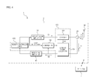
- FIG. 1 is a block diagram illustrating a construction of an apparatus for removing a transmission leakage signal of an RFID system according to a first embodiment of the present disclosure.
- the apparatus 100 for removing a transmission leakage signal of the RFID system 1 is constructed of a reader controller 110, a divider 120, a leakage signal canceller 130, and a controller 140.
- the RFID system 1 is generally constructed of an RFID reader 3 and an RFID tag 5.
- the RFID reader 3 includes the apparatus 100 for removing a transmission leakage signal, which identifies tag information stored in the RFID tag 5 by transmitting and receiving RF signal to and from the RFID tag 5.
- the RFID reader 3 outputs a transmission signal S1 so as to send it to the RFID tag 5, and receives a receiving signal S2 sent from the RFID tag 5 so as to read tag information of the RFID tag 5.
- the reader controller (CPU) 110 is a microcomputer that generally controls the RFID reader 3, outputting the transmission signal S1 to be sent to the RFID tag 5.
- the transmission signal S1 is amplified by the transmission amplifier 10 and radiated through an antenna 30 by way of the divider 120 and the isolator 20.
- the reader controller (CPU)(110) receives the receiving signal S2 through the antenna 30 and reads tag information of the RFID tag 5. At this time, the receiving signal S2 received through the antenna 30 is transferred to a receiving amplifier 40 by the isolator 20, and the receiving amplifier 40 amplifies the receiving signal S2 and then transmits it to the reader controller 110.
- the reader controller 110 periodically sets an anti-collision period in which a relevant receiving signal S2 can be sent from each RFID tag 5 in order to prevent a collision from occurring among a plurality of tag information (that is, a plurality of receiving signals sent from the RFID tag 5).
- each RFID tag 5 sends the receiving signal S2 at the anti-collision period.
- the divider 120 outputs the divided signal S4 that is a portion of the transmission signal S1 branched, to the leakage signal canceller 130.
- the leakage signal canceller 130 receive the divided signal S4 output from the divider 120 and the receiving signal S2, generates a cancellation signal and couples it with the receiving signal S2 (in which the transmission leakage signal S3 is mixed) in order to cancel the transmission leakage signal S3 included in the receiving signal S2 according to a control of the controller 140.
- the transmission leakage signal S3 included in the receiving signal S2 is cancelled by the cancellation signal so that only a pure receiving signal S2 is transferred to the receiving amplifier 40.
- the leakage signal canceller 130 generates a cancellation signal on the basis of the divided signal S4 that is divided from the transmission signal S1. At this time, the cancellation signal has the same amplitude and the opposite phase as the transmission leakage signal S3.
- an adjustment task to remove the transmission leakage signal S3 is performed when the leakage signal canceller 130 receives the divided signal S4 and the receiving signal S2, resets the adjustment condition according to an adjustment value when the adjustment value is transferred from the controller 140 and generates a cancellation signal according to the reset adjustment condition.
- the controller 140 performs an operation to search and detect an adjustment value used to prevent the transmission signal S1 from being mixed into the receiving signal S2 as much as possible, among the adjustment values.
- the adjustment value is a value that is set in the leakage signal canceller 130 to remove the transmission leakage signal S3 mixed into the receiving signal S2, which can make the receiving signal as less as possible in order to prevent the transmission signal S1 from being mixed into the receiving signal S2 (that is, in order that the transmission signal S1 affects the receiving signal as less as possible).
- the controller 140 is a means that operates separately from the reader controller 110, that is, operates independently from the reader controller 110, which controls an operation of the leakage signal canceller 130 to remove the transmission leakage signal S3 mixed into the receiving signal S2.
- the controller 140 receives the receiving signal S2 from the RFID tag 5 in the RF environment, and confirms whether there is a change of the RF environment for the RF tag 5 using the intensity of the receiving signal S2.
- the change of the RF environment means that the size and number of the RFID 5 are changed or the position of the RFID 5 is changed, which can be confirmed using the intensity of the receiving signal sent from the RFID tag 5 in the RF environment or the like.
- the controller 140 redetect an adjustment value to remove the transmission leakage signal S3 caused according to the change of the RF environment, and resets the adjustment condition by applying the redetected adjustment value to the leakage signal canceller 130, so that the controller 140 can perform the adjustment task again to generate the cancellation signal using the leakage signal canceller 130.
- the controller 140 detects the adjustment value by finding the minimum value of the intensity of the receiving signal S2, that is, the amount of the receiving signal S2, zero (0).
- the intensity of the receiving signal S2 approximates to the minimum value, zero (0).
- the controller 140 should perform an adjustment task for this according to a change of the RF environment.
- the controller 140 redetects an adjustment value to make the intensity of the receiving signal S2 minimum, and applies the redetected adjustment value to the leakage signal canceller 130, so that the intensity of the receiving signal S2 has the minimum value (that is, a value less than a reference value) even when the adjustment condition is changed and the RF environment is changed.
- the redetected adjustment value means an adjustment value detected as a result of searching an adjustment value in order that the minimum intensity of the receiving signal is found among the plurality of the adjustment values that are already stored in the controller 140.
- the intensity of the receiving signal should be checked when the RFID reader 3 is operated.
- the leakage signal canceller 130 it is possible to enable the leakage signal canceller 130 to make an adjustment task quickly by making the intensity of the receiving signal S2 checked always and the controller 140 operated separately from the reader controller 110 to make a readjustment when the intensity of the receiving signal S2 becomes higher.
- the controller 140 enables the leakage signal canceller 130 to perform an adjustment task when the RF environment changes even in an anti-collision period.
- the function to read the tag is performed in the reader controller 110 and the function to control the leakage signal canceller 130 according to the change of the RF environment is performed in the controller 140, so that it is possible to efficiently remove the transmission leakage signal according to the change of the RF environment even in the anti-collision period and accordingly to meet the change of the RF environment promptly and reduce the load of the reader controller 110.
- FIG.2 is a block diagram illustrating a construction of an apparatus for removing a transmission leakage signal of an RFID system according to a second embodiment of the present disclosure.
- an apparatus 100 for removing a transmission leakage signal of an RFID system 1 is constructed of a reader controller 110, a divider 120, a first leakage signal canceller 132, a second leakage signal canceller 134 and a controller 140.
- the first leakage signal canceller 132 receives the divided signal S4 and the receiving signal 132 in the state that an adjustment condition was set already, resets an adjustment condition according to an adjustment value transferred from the controller 140, and generates a cancellation signal according to the reset adjustment condition, so that it performs an adjustment task to remove the transmission leakage signal S3.
- the second leakage signal canceller 134 sets an adjustment condition by applying the adjustment value transferred from the controller 140, generates a cancellation signal to cancel the transmission leakage signal S3 included in the receiving signal S2 according to the set adjustment condition, performs an adjustment task to remove the transmission leakage signal using the cancellation signal, and outputs the receiving signal S2 from which the leakage signal is removed, to the controller 140.
- the controller 140 determines whether an adjustment task to cancel the cancellation leakage signal S3 is properly performed using the receiving signal S2 output from the second leakage signal canceller 134 (that is, whether the intensity of the receiving signal S2 is minimum), and enables the first leakage signal canceller 132 to perform an adjustment task to remove the transmission leakage signal S3 by applying a relevant adjustment value to the first leakage signal canceller 132 when the adjustment task was properly performed.
- the controller 140 redetects the adjustment value to apply it to the second leakage signal canceller 134, and the second leakage signal canceller 134 repeats a procedure to perform the adjustment task again using the redetected adjustment value and outputs the receiving signal S2 again that is output as a result of performing the adjustment task, so that a task to detect the optimum adjustment value is performed.
- the second leakage signal canceller 134 is used to detect an adjustment value to make the intensity of the receiving signal S2 minimum, so that an operation time can be reduced compared with when one leakage signal canceller 130 is used.
- controller 140 performs a readjustment task of the leakage signal canceller 130 when there is a change of the RF environment even in the anti-collision period.
- the reader controller 110 may be constructed to control an operation time of the controller 140.
- FIG.3 is a block diagram illustrating a construction of an apparatus for removing a transmission leakage signal of an RIFD system according to a third embodiment of the present disclosure.
- an apparatus 100 for removing the transmission leakage signal of an RFID system 1 is constructed of a reader controller 110, a divider 120, a leakage signal canceller 130 and a controller 140.
- a reader controller 110 is a microcomputer that generally controls the RFID reader, which also performs functions to output the transmission signal S1 to be sent to the RFID tag 5 and to control an operation of the controller 140 using on/off control signal in order to determine an operation point of the leakage signal canceller 130 in addition to a function to read information of the RFID tag 5.
- the controller 140 controls to perform an adjustment task to search and detect an adjustment value and apply it to the leakage signal canceller 130, so that the leakage signal canceller 130 can generate a cancellation signal corresponding to the transmission leakage signal and remove the transmission leakage signal.
- the controller 140 controls to confirm whether there is a change of the RF environment and to perform a readjustment task in the leakage signal canceller 130 according to the RF environment when it is confirmed that there is a change of the RF environment.
- FIG.4 is. a block diagram illustrating a construction of an apparatus for removing a transmission leakage signal of an RIFD system according to a fourth embodiment of the present disclosure.
- an apparatus 100 for removing transmission leakage signal of the RFID system 1 is constructed of a reader controller 110, a divider 120, a leakage signal canceller 130 and a controller 140.
- the reader controller 110 is a microcomputer to generally control the RFID reader, which performs functions to output the transmission signal S1 to be sent to the RFID tag 5, read tag information of the RFID tag 5 and determine an operation time of the leakage signal canceller 130 additionally using a portion of the transmission signal S1 as on/off control signal.
- the reader controller 110 determines whether there is a change of the RF environment, and sends the transmission signal S1 when it is confirmed that the RF environment is changed. At this time, the reader controller 110 transfers a portion of the transmission signal S1 to the controller 140. Further, when the controller 140 receives the portion of the transmission signal S1, it searches and detects an adjustment value so as to apply it to the leakage signal canceller 130 so that the leakage signal canceller 130 can perform a readjustment task according to the change of the RF environment.
- the controller 140 confirms whether there is a change of the RF environment.
- the controller searches and detects an adjustment according to the change of the RF environment so that the leakage signal canceller 130 can perform an adjustment task.
- the leakage signal canceller 130 performs the adjustment task according to the adjustment value detected so that it is possible to control the operation of the leakage signal canceller 130 more precisely according to the change of the RF environment.
- the reader controller 110 can perform an operation to cancel the transmission leakage signal, and the controller 140 can perform a function to read the tag information according a control of the controller 110.
- each leakage signal canceller performs an operation to cancel the transmission leakage signal according to an adjustment value.
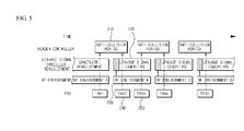
- FIG. 5 is a time chart explaining a transmission leakage signal removal in an RIFD system according to an embodiment of the present disclosure.
- a reader controller 110 sets an anti-collision period 210 according to a period set in advance.
- Each RFID tag 5 sends a receiving signal S2 to the RFID reader within each anti-collision period that is set as described above so that it is possible to prevent the plurality of receiving signals S2 from colliding among them.
- the controller 140 continuously confirms whether there is a change of RF environment 230 with which the receiving signal is received from the plurality of the RFID tags, even in each anti-collision period.
- the readjustment task of the leakage signal canceller 130 is a task to cancel the transmission leakage signal S3 included in the tag signal that is received in the RFID reader, which refers to receiving a tag signal from a tag in the changed RF environment, generating a cancellation signal to cancel the transmission leakage signal S3 included in the tag signal and coupling the cancellation signal with the received tag signal.
- the transmission leakage signal S3 included in the tag signal is removed because of the coupling so that a pure tag signal can be transferred.
- an anti-collision period has several milliseconds to tens of seconds and there may be a situation in which the leakage signal canceller 130 may not perform the readjustment task during the anti-collision period and the reader may not receive the tag signal after an RF environment change when there occurs a change of the RE environment.
Abstract
Description
- The present disclosure relates to an apparatus for removing a transmission leakage signal of an RFID system, capable of removing a transmission leakage signal in a Radio Frequency Identification (referred to as 'RFID', hereinafter) system, and an RFID system having the same.
- Generally, an RFID system is widely used in a system for transmitting and receiving information in a variety of fields such as approval management, document management, distribution management, identification and radio authentication, which includes a plurality of tags on which tag information is recorded and a reader to read tag information included in the tag.
- The plurality of tags that exist in the same radio frequency field in such an RFID system are activated by the reader, the tags transmit their own tag information to the reader so that there occurs a collision among a plurality of tag information.
- Accordingly, in order to solve the above described problem, the reader periodically transmits an anti-collision period that is a time when each tag can send the tag information, so as to prevent the plurality of tag information from colliding among them.
- Meanwhile, in order to isolate a transmission signal from a receiving signal in an RFID system in which a radio signal is transmitted and received together, a separate isolation device such as an isolator is used.
- Since there occurs a phenomenon in which the reader cannot receive a receiving signal well due to the fact that a portion of a transmission signal is leaked and mixed into the receiving signal while the transmission signal is transmitted and a receiving signal is received, the reader includes a separate leakage canceller to cancel such a transmission leakage signal, so that it performs an adjustment task to generate a cancellation signal.
- However, while a set condition of the leakage signal canceller should be changed to cancel the transmission leakage signal that changes according to an RF environment when an RF environment having tags installed therein changes, a reader controller to control a reader in the RFID system in the art is engaged only in a task to read the tag during an anti-collision period so that there occurs a problem that the set condition cannot be changed according to a change of the RF environment.
- Further, there was a limitation to suitably counteract a market requirement according to the change of RF environment since it is difficult to change a setting condition of a transmission leakage canceller to a new RF environment in an anti-collision period with the reader controller in the art, and it is not easy to correctly read tag information.
- The present disclosure provides an apparatus for removing a transmission leakage signal of an RFID system, capable of performing a function to read an RFID tag and a function to adjust a leakage signal canceller to remove a transmission leakage signal, independently.
- Further, the present disclosure provides an apparatus for removing a transmission leakage signal of an RFID system, capable of readjusting a leakage signal canceller according to a change of an RF environment and removing a transmission leakage signal, even in an anti-collision period.
- According to an aspect of the present disclosure, there is provided a n RFID system including a reader controller that sends a transmission signal to an RFID tag and receives a receiving signal transmitted from the RFID tag to read tag information, and a transmission leakage signal removing module that removes a transmission leakage signal mixed into the receiving signal, wherein the transmission leakage signal removing module may comprise a leakage signal canceller that receives a portion of the transmission signal and the receiving signal, and performs an adjustment task to generate a cancellation signal according to an adjustment value to remove a transmission leakage signal and the portion of the transmission signal, and to remove the transmission leakage signal included in the receiving signal; and a controller that continuously determines whether there is a change of an RF environment using an intensity of the receiving signal, the RFID tag being installed in the RF environment, and controls an operation of the leakage signal canceller according to the change of the RF environment.
- According to an embodiment of the present disclosure, the controller continuously compares the intensity of the receiving signal with a reference value, and determines that there is a change in the RF environment when the intensity of the receiving signal is equal to or greater than the reference value.
- According to an embodiment of the present disclosure, the controller detects an adjustment value that makes the intensity of the receiving signal less than the reference value and transfers the adjustment value to the leakage signal canceller when it is determined that there is a change in the RF environment, and the leakage signal canceller performs an adjustment task to generate a cancellation signal according to the adjustment value transferred and remove the transmission leakage signal included in the receiving signal.
- According to an embodiment of the present disclosure, the controller continuously determines whether the RF environment is changed even in an anti-collision period that is set by the reader controller according to a predetermined period, the RFID tag being installed in the RF environment.
- According to an embodiment of the present disclosure, the apparatus may further include a divider that divides a portion of the transmission signal and outputs a divided signal.
- According to an embodiment of the present disclosure, the cancellation signal has the same amplitude and the opposite phase as the transmission leakage signal.
- According to an embodiment of the present disclosure, the leakage signal canceller includes a first leakage signal canceller that performs an adjustment task to generate a cancellation signal according to the adjustment value and cancel the transmission leakage signal included in the receiving signal; and a second leakage signal canceller that outputs the receiving signal to the controller, after the adjustment task to generate the cancellation signal according to the adjustment value and cancel the transmission leakage signal included in the receiving signal.
- According to an embodiment of the present disclosure, the controller determines whether the intensity of the receiving signal inputted from the second leakage signal canceller is equal to or greater than a reference value, redetects the adjustment value and applies the adjustment value to the second leakage signal canceller when the intensity of the receiving signal is equal to or greater than the reference signal, repeatedly performs the determination and application processes until the intensity of the receiving signal becomes less than the reference value, and when the intensity of the receiving signal becomes less than the reference signal, applies an adjustment value corresponding to the intensity of the receiving signal to the first leakage signal canceller.
- According to an embodiment of the present disclosure, the controller controls an operation time of the leakage signal canceller according to an on/off control signal inputted from the reader controller.
- According to an embodiment of the present disclosure, the controller confirms whether there is a change in the RF environment when the on control signal is input from the reader controller, the RFID tag being installed in the RF environment, and controls an operation of the leakage signal canceller according to the change of the RF environment.
- The RFID system according to the present disclosure has an advantageous effect in that a transmission leakage signal included in the receiving signal is removed more effectively when a transmission and a reception are performed together in an RFID system so that a receive sensitivity can be enhanced and a tag reading can be performed more precisely.
- The RFID system according to the present disclosure has another advantageous effect in that it is possible to enhance a reliability of both functions by independently performing a function to read a tag and a function to remove a transmission leakage signal in an RFID system.
- The RFID system according to the present disclosure has another advantageous effect in that it is possible to use a cheap CPU and accordingly enhance a competitiveness of product in price since a reader controller is wholly charged for reading a tag only.
- The RFID system according to the present disclosure has another advantageous effect in that a transmission leakage signal can be efficiently removed by readjusting a leakage signal canceller according to a change of an RF environment even in an anti-collision period in the RFID system.
- The accompanying drawings, which are included to provide a further understanding of the disclosure and are incorporated in and constitute a part of this application, illustrate embodiments of the disclosure and together with the description, serve to explain the principle of the disclosure. In the drawings:
-
FIG.1 is a block diagram illustrating a construction of an apparatus for removing a transmission leakage signal of an RFID system according to a first embodiment of the present disclosure; -
FIG.2 is a block diagram illustrating a construction of an apparatus for removing a transmission leakage signal of an RFID system according to a second embodiment of the present disclosure; -
FIG.3 is a block diagram illustrating a construction of an apparatus for removing a transmission leakage signal of an RIFD system according to a third embodiment of the present disclosure; -
FIG. 4 is. a block diagram illustrating a construction of an apparatus for removing a transmission leakage signal of an RIFD system according to a fourth embodiment of the present disclosure; and -
FIG. 5 is a time chart explaining a transmission leakage signal removal in an RIFD system according to an embodiment of the present disclosure. - Hereinafter, a preferred embodiment of the present disclosure will be described with reference to the accompanying drawings. Further, when it is determined that a detailed explanation of known function or construction related when describing the present disclosure unnecessarily obscures the gist of the present disclosure, its detailed description will be omitted.
-
FIG. 1 is a block diagram illustrating a construction of an apparatus for removing a transmission leakage signal of an RFID system according to a first embodiment of the present disclosure. - Referring to
FIG.1 , theapparatus 100 for removing a transmission leakage signal of theRFID system 1 is constructed of areader controller 110, adivider 120, aleakage signal canceller 130, and acontroller 140. - The
RFID system 1 is generally constructed of anRFID reader 3 and anRFID tag 5. TheRFID reader 3 includes theapparatus 100 for removing a transmission leakage signal, which identifies tag information stored in theRFID tag 5 by transmitting and receiving RF signal to and from theRFID tag 5. - For this, the
RFID reader 3 outputs a transmission signal S1 so as to send it to theRFID tag 5, and receives a receiving signal S2 sent from theRFID tag 5 so as to read tag information of theRFID tag 5. - The reader controller (CPU) 110 is a microcomputer that generally controls the
RFID reader 3, outputting the transmission signal S1 to be sent to theRFID tag 5. The transmission signal S1 is amplified by thetransmission amplifier 10 and radiated through anantenna 30 by way of thedivider 120 and theisolator 20. - Further, the reader controller (CPU)(110) receives the receiving signal S2 through the
antenna 30 and reads tag information of theRFID tag 5. At this time, the receiving signal S2 received through theantenna 30 is transferred to areceiving amplifier 40 by theisolator 20, and thereceiving amplifier 40 amplifies the receiving signal S2 and then transmits it to thereader controller 110. - Further, the
reader controller 110 periodically sets an anti-collision period in which a relevant receiving signal S2 can be sent from eachRFID tag 5 in order to prevent a collision from occurring among a plurality of tag information (that is, a plurality of receiving signals sent from the RFID tag 5). - Then, each
RFID tag 5 sends the receiving signal S2 at the anti-collision period. - Meanwhile, there occurs a phenomenon that a portion of the transmission signal S1 is leaked so that the transmission leakage signal S3 is mixed into the receiving signal S3 while the transmission signal S1 is sent and the receiving signal S2 is received.
- As such, in order to cancel the transmission leakage signal S3 mixed into the receiving signal S2, the
divider 120 outputs the divided signal S4 that is a portion of the transmission signal S1 branched, to theleakage signal canceller 130. - The
leakage signal canceller 130 receive the divided signal S4 output from thedivider 120 and the receiving signal S2, generates a cancellation signal and couples it with the receiving signal S2 (in which the transmission leakage signal S3 is mixed) in order to cancel the transmission leakage signal S3 included in the receiving signal S2 according to a control of thecontroller 140. - By doing this, the transmission leakage signal S3 included in the receiving signal S2 is cancelled by the cancellation signal so that only a pure receiving signal S2 is transferred to the receiving
amplifier 40. - The
leakage signal canceller 130 generates a cancellation signal on the basis of the divided signal S4 that is divided from the transmission signal S1. At this time, the cancellation signal has the same amplitude and the opposite phase as the transmission leakage signal S3. - If describing the above in more detail, in the state that an adjustment condition to remove the transmission leakage signal S3 is set in advance in the
leakage signal canceller 130, an adjustment task to remove the transmission leakage signal S3 is performed when theleakage signal canceller 130 receives the divided signal S4 and the receiving signal S2, resets the adjustment condition according to an adjustment value when the adjustment value is transferred from thecontroller 140 and generates a cancellation signal according to the reset adjustment condition. - For this, the
controller 140 performs an operation to search and detect an adjustment value used to prevent the transmission signal S1 from being mixed into the receiving signal S2 as much as possible, among the adjustment values. - Here, the adjustment value is a value that is set in the
leakage signal canceller 130 to remove the transmission leakage signal S3 mixed into the receiving signal S2, which can make the receiving signal as less as possible in order to prevent the transmission signal S1 from being mixed into the receiving signal S2 (that is, in order that the transmission signal S1 affects the receiving signal as less as possible). - The
controller 140 is a means that operates separately from thereader controller 110, that is, operates independently from thereader controller 110, which controls an operation of theleakage signal canceller 130 to remove the transmission leakage signal S3 mixed into the receiving signal S2. - In more detail, the
controller 140 receives the receiving signal S2 from theRFID tag 5 in the RF environment, and confirms whether there is a change of the RF environment for theRF tag 5 using the intensity of the receiving signal S2. - Here, the change of the RF environment means that the size and number of the
RFID 5 are changed or the position of theRFID 5 is changed, which can be confirmed using the intensity of the receiving signal sent from theRFID tag 5 in the RF environment or the like. - Further, when there is a change of the RF environment, the
controller 140 redetect an adjustment value to remove the transmission leakage signal S3 caused according to the change of the RF environment, and resets the adjustment condition by applying the redetected adjustment value to theleakage signal canceller 130, so that thecontroller 140 can perform the adjustment task again to generate the cancellation signal using theleakage signal canceller 130. - Meanwhile, the
controller 140 detects the adjustment value by finding the minimum value of the intensity of the receiving signal S2, that is, the amount of the receiving signal S2, zero (0). - In more detail, since the transmission leakage signal S3 is removed from the receiving signal S2 already when it passes through the
leakage signal canceller 130, the intensity of the receiving signal S2 approximates to the minimum value, zero (0). However, since the intensity of the receiving signal S2 becomes high when the RF environment is changed even though passing through the leakage signal canceller 130 (that is, the intensity of the receiving signal is equal to or greater than a reference value), thecontroller 140 should perform an adjustment task for this according to a change of the RF environment. - Accordingly, the
controller 140 redetects an adjustment value to make the intensity of the receiving signal S2 minimum, and applies the redetected adjustment value to theleakage signal canceller 130, so that the intensity of the receiving signal S2 has the minimum value (that is, a value less than a reference value) even when the adjustment condition is changed and the RF environment is changed. - Here, the redetected adjustment value means an adjustment value detected as a result of searching an adjustment value in order that the minimum intensity of the receiving signal is found among the plurality of the adjustment values that are already stored in the
controller 140. - In order to detect the adjustment value, the intensity of the receiving signal should be checked when the
RFID reader 3 is operated. - As such, it is possible to enable the
leakage signal canceller 130 to make an adjustment task quickly by making the intensity of the receiving signal S2 checked always and thecontroller 140 operated separately from thereader controller 110 to make a readjustment when the intensity of the receiving signal S2 becomes higher. - Meanwhile, the
controller 140 enables theleakage signal canceller 130 to perform an adjustment task when the RF environment changes even in an anti-collision period. - As described above, the function to read the tag is performed in the
reader controller 110 and the function to control theleakage signal canceller 130 according to the change of the RF environment is performed in thecontroller 140, so that it is possible to efficiently remove the transmission leakage signal according to the change of the RF environment even in the anti-collision period and accordingly to meet the change of the RF environment promptly and reduce the load of thereader controller 110. -
FIG.2 is a block diagram illustrating a construction of an apparatus for removing a transmission leakage signal of an RFID system according to a second embodiment of the present disclosure. - Referring to
FIG.2 , anapparatus 100 for removing a transmission leakage signal of anRFID system 1 is constructed of areader controller 110, adivider 120, a firstleakage signal canceller 132, a secondleakage signal canceller 134 and acontroller 140. - Hereinafter, since the same function was described in the first embodiment, its description will be omitted.
- The first
leakage signal canceller 132 receives the divided signal S4 and the receivingsignal 132 in the state that an adjustment condition was set already, resets an adjustment condition according to an adjustment value transferred from thecontroller 140, and generates a cancellation signal according to the reset adjustment condition, so that it performs an adjustment task to remove the transmission leakage signal S3. - The second
leakage signal canceller 134 sets an adjustment condition by applying the adjustment value transferred from thecontroller 140, generates a cancellation signal to cancel the transmission leakage signal S3 included in the receiving signal S2 according to the set adjustment condition, performs an adjustment task to remove the transmission leakage signal using the cancellation signal, and outputs the receiving signal S2 from which the leakage signal is removed, to thecontroller 140. - The
controller 140 determines whether an adjustment task to cancel the cancellation leakage signal S3 is properly performed using the receiving signal S2 output from the second leakage signal canceller 134 (that is, whether the intensity of the receiving signal S2 is minimum), and enables the firstleakage signal canceller 132 to perform an adjustment task to remove the transmission leakage signal S3 by applying a relevant adjustment value to the firstleakage signal canceller 132 when the adjustment task was properly performed. - If the adjustment task to cancel the transmission leakage signal S3 was not properly performed, the
controller 140 redetects the adjustment value to apply it to the secondleakage signal canceller 134, and the secondleakage signal canceller 134 repeats a procedure to perform the adjustment task again using the redetected adjustment value and outputs the receiving signal S2 again that is output as a result of performing the adjustment task, so that a task to detect the optimum adjustment value is performed. - As such, the second
leakage signal canceller 134 is used to detect an adjustment value to make the intensity of the receiving signal S2 minimum, so that an operation time can be reduced compared with when oneleakage signal canceller 130 is used. - Further, the
controller 140 performs a readjustment task of theleakage signal canceller 130 when there is a change of the RF environment even in the anti-collision period. - Meanwhile, in an embodiment of the present disclosure, the
reader controller 110 may be constructed to control an operation time of thecontroller 140. -
FIG.3 is a block diagram illustrating a construction of an apparatus for removing a transmission leakage signal of an RIFD system according to a third embodiment of the present disclosure. - Referring to
FIG.3 , anapparatus 100 for removing the transmission leakage signal of anRFID system 1 is constructed of areader controller 110, adivider 120, aleakage signal canceller 130 and acontroller 140. - Hereinafter, the construction having the same function will be omitted since it was described in the first and second embodiments.
- A
reader controller 110 is a microcomputer that generally controls the RFID reader, which also performs functions to output the transmission signal S1 to be sent to theRFID tag 5 and to control an operation of thecontroller 140 using on/off control signal in order to determine an operation point of theleakage signal canceller 130 in addition to a function to read information of theRFID tag 5. - In more detail, when the
reader controller 110 outputs an on control signal to thecontroller 140, thecontroller 140 controls to perform an adjustment task to search and detect an adjustment value and apply it to theleakage signal canceller 130, so that theleakage signal canceller 130 can generate a cancellation signal corresponding to the transmission leakage signal and remove the transmission leakage signal. - Meanwhile, when the
reader controller 110 outputs an on control signal to thecontroller 140, thecontroller 140 controls to confirm whether there is a change of the RF environment and to perform a readjustment task in theleakage signal canceller 130 according to the RF environment when it is confirmed that there is a change of the RF environment. - As such, it is possible to control the operation of the
leakage signal canceller 130 more precisely when thereader controller 110 determines an operation time of theleakage signal canceller 130. -
FIG.4 is. a block diagram illustrating a construction of an apparatus for removing a transmission leakage signal of an RIFD system according to a fourth embodiment of the present disclosure. - Referring to
FIG.4 , anapparatus 100 for removing transmission leakage signal of theRFID system 1 is constructed of areader controller 110, adivider 120, aleakage signal canceller 130 and acontroller 140. - Hereinafter, the construction having the same function is omitted since it was described in the first to third embodiments.
- The
reader controller 110 is a microcomputer to generally control the RFID reader, which performs functions to output the transmission signal S1 to be sent to theRFID tag 5, read tag information of theRFID tag 5 and determine an operation time of theleakage signal canceller 130 additionally using a portion of the transmission signal S1 as on/off control signal. - In more detail, the
reader controller 110 determines whether there is a change of the RF environment, and sends the transmission signal S1 when it is confirmed that the RF environment is changed. At this time, thereader controller 110 transfers a portion of the transmission signal S1 to thecontroller 140. Further, when thecontroller 140 receives the portion of the transmission signal S1, it searches and detects an adjustment value so as to apply it to theleakage signal canceller 130 so that theleakage signal canceller 130 can perform a readjustment task according to the change of the RF environment. - Meanwhile, when the
reader controller 110 transmits the portion of the transmission signal S1 to thecontroller 140, thecontroller 140 confirms whether there is a change of the RF environment. When it is confirmed that there is a change of the RF environment, the controller searches and detects an adjustment according to the change of the RF environment so that theleakage signal canceller 130 can perform an adjustment task. - As described above, when the
reader controller 110 sends the transmission signal S1, a portion of the transmission signal S1 is transferred to thecontroller 140 so that the adjustment value can be detected. Further, theleakage signal canceller 130 performs the adjustment task according to the adjustment value detected so that it is possible to control the operation of theleakage signal canceller 130 more precisely according to the change of the RF environment. - Additionally, the
reader controller 110 can perform an operation to cancel the transmission leakage signal, and thecontroller 140 can perform a function to read the tag information according a control of thecontroller 110. - Further, it is possible to have a construction in which it includes a plurality of leakage signal cancellers and each leakage signal canceller performs an operation to cancel the transmission leakage signal according to an adjustment value.
-
FIG. 5 is a time chart explaining a transmission leakage signal removal in an RIFD system according to an embodiment of the present disclosure. - Referring to
FIG. 5 , in the RFID system according to the present disclosure, areader controller 110 sets ananti-collision period 210 according to a period set in advance. - Each
RFID tag 5 sends a receiving signal S2 to the RFID reader within each anti-collision period that is set as described above so that it is possible to prevent the plurality of receiving signals S2 from colliding among them. - At this time, the
controller 140 continuously confirms whether there is a change ofRF environment 230 with which the receiving signal is received from the plurality of the RFID tags, even in each anti-collision period. - It is for the purpose of detecting an adjustment value according to a change of the RF environment when there is a change of the RF environment and performing a
readjustment task 220 in theleakage signal canceller 130. - Here, the readjustment task of the
leakage signal canceller 130 is a task to cancel the transmission leakage signal S3 included in the tag signal that is received in the RFID reader, which refers to receiving a tag signal from a tag in the changed RF environment, generating a cancellation signal to cancel the transmission leakage signal S3 included in the tag signal and coupling the cancellation signal with the received tag signal. - The transmission leakage signal S3 included in the tag signal is removed because of the coupling so that a pure tag signal can be transferred.
- At this time, an anti-collision period has several milliseconds to tens of seconds and there may be a situation in which the
leakage signal canceller 130 may not perform the readjustment task during the anti-collision period and the reader may not receive the tag signal after an RF environment change when there occurs a change of the RE environment. - As such, it is possible to precisely identify tag information even when the RF environment changes by making the tag signal received from the tag that is in the changed RF environment when the RF environment around the tag even during the same anti-collision period.
- Therefore, it is possible to precisely receive the tag signal from the tag that is in the changed RF environment by confirming the change of the RF environment according to a period set in advance and continuously performing an readjustment task of the
leakage signal canceller 130 according to the change of the RF environment. - Hereinbefore, while the embodiments of the present disclosure are described, they are exemplary ones only and one of ordinary skill in the art may recognize that various alterations and modifications that fall within the scope of the present disclosure may be possible. Accordingly, the true technical protection scope of the present disclosure should be defined by the following claims.
Claims (10)
- An RFID system (1) including a reader controller (110) that sends a transmission signal to an RFID tag and receives a receiving signal transmitted from the RFID tag to read tag information, and a transmission leakage signal removing module that removes a transmission leakage signal mixed into the receiving signal, characterized in that the transmission leakage signal removing module characterized by:a leakage signal canceller (130) that receives a portion of the transmission signal and the receiving signal, and performs an adjustment task to generate a cancellation signal according to an adjustment value to remove a transmission leakage signal and the portion of the transmission signal, and to remove the transmission leakage signal included in the receiving signal; anda controller (140) that continuously determines whether there is a change of an RF environment using an intensity of the receiving signal, the RFID tag being installed in the RF environment, and controls an operation of the leakage signal canceller according to the change of the RF environment.
- The RFID system of claim 1, characterized in that the controller (140) continuously compares the intensity of the receiving signal with a reference value, and determines that there is a change in the RF environment when the intensity of the receiving signal is equal to or greater than the reference value.
- The RFID system of claim 2, characterized in that the controller (140) detects an adjustment value that makes the intensity of the receiving signal less than the reference value and transfers the adjustment value to the leakage signal canceller (130) when it is determined that there is a change in the RF environment, and the leakage signal canceller performs an adjustment task to generate a cancellation signal according to the adjustment value transferred and remove the transmission leakage signal included in the receiving signal.
- The RFID system of claim 1, characterized in that the controller (140) continuously determines whether the RF environment is changed even in an anti-collision period that is set by the reader controller (110) according to a predetermined period, the RFID tag being installed in the RF environment.
- The RFID system of claim 1, characterized in that the RFID system further comprises a divider (120) that divides a portion of the transmission signal and outputs a divided signal.
- The RFID system of claim 1, characterized in that the cancellation signal has the same amplitude and the opposite phase as the transmission leakage signal.
- The RFID system of claim 3, characterized in that the leakage signal canceller (130) includes:a first leakage signal canceller (132) that performs an adjustment task to generate a cancellation signal according to the adjustment value and cancel the transmission leakage signal included in the receiving signal; anda second leakage signal canceller (134) that outputs the receiving signal to the controller, after the adjustment task to generate the cancellation signal according to the adjustment value and cancel the transmission leakage signal included in the receiving signal.
- The RFID system of claim 7, characterized in that the controller (140) determines whether the intensity of the receiving signal inputted from the second leakage signal canceller (134) is equal to or greater than a reference value, redetects the adjustment value and applies the adjustment value to the second leakage signal canceller (134) when the intensity of the receiving signal is equal to or greater than the reference signal, repeatedly performs the determination and application processes until the intensity of the receiving signal becomes less than the reference value, and when the intensity of the receiving signal becomes less than the reference signal, applies an adjustment value corresponding to the intensity of the receiving signal to the first leakage signal canceller (132).
- The RFID system of claim 1, characterized in that the controller 140 controls an operation time of the leakage signal canceller (130) according to an on/off control signal inputted from the reader controller (110).
- The RFID system of claim 9, characterized in that, when the on control signal is input from the reader controller (110), the controller (140) confirms whether there is a change in the RF environment in which the RFID tag is installed, and controls an operation of the leakage signal canceller (130) according to the change of the RF environment.
Applications Claiming Priority (1)
| Application Number | Priority Date | Filing Date | Title |
|---|---|---|---|
| KR1020100046665A KR101386839B1 (en) | 2010-05-18 | 2010-05-18 | Leakage signal cancellation apparatus of rfid system |
Publications (2)
| Publication Number | Publication Date |
|---|---|
| EP2388927A2 true EP2388927A2 (en) | 2011-11-23 |
| EP2388927A3 EP2388927A3 (en) | 2014-07-30 |
Family
ID=44487202
Family Applications (1)
| Application Number | Title | Priority Date | Filing Date |
|---|---|---|---|
| EP11165976.9A Withdrawn EP2388927A3 (en) | 2010-05-18 | 2011-05-13 | Apparatus for removing transmission leakage signal in RFID system and RFID system having the same |
Country Status (5)
| Country | Link |
|---|---|
| US (1) | US8742898B2 (en) |
| EP (1) | EP2388927A3 (en) |
| JP (1) | JP5140176B2 (en) |
| KR (1) | KR101386839B1 (en) |
| CN (1) | CN102254134B (en) |
Cited By (7)
| Publication number | Priority date | Publication date | Assignee | Title |
|---|---|---|---|---|
| WO2014139579A1 (en) * | 2013-03-14 | 2014-09-18 | Telefonaktiebolaget L M Ericsson (Publ) | Transmitter receiver leakage reduction in a full duplex system without the use of a duplexer |
| US9667404B2 (en) | 2012-06-07 | 2017-05-30 | Telefonaktiebolaget Lm Ericsson (Publ) | Duplexer-less transceiver and communication apparatus |
| US9871552B2 (en) | 2013-04-30 | 2018-01-16 | Telefonaktiebolaget Lm Ericsson (Publ) | Transceiver arrangement, communication device, method and computer program |
| US9900044B2 (en) | 2014-01-21 | 2018-02-20 | Telefonaktiebolaget Lm Ericsson (Publ) | Transceiver arrangement and communication device |
| US10027465B2 (en) | 2013-04-26 | 2018-07-17 | Telefonaktiebolaget Lm Ericsson | Transceiver arrangement, communication device, method and computer program |
| US10084506B2 (en) | 2012-11-15 | 2018-09-25 | Telefonaktiebolaget Lm Ericsson (Publ) | Transceiver front-end |
| US10200079B2 (en) | 2014-10-29 | 2019-02-05 | Telefonaktiebolaget Lm Ericsson (Publ) | Transceiver arrangement and communication device |
Families Citing this family (9)
| Publication number | Priority date | Publication date | Assignee | Title |
|---|---|---|---|---|
| KR101386821B1 (en) * | 2010-05-17 | 2014-04-18 | 엘에스산전 주식회사 | Leakage signal cancellation apparatus of rfid system |
| US10374656B2 (en) * | 2012-07-30 | 2019-08-06 | Photonic Systems, Inc. | Same-aperture any-frequency simultaneous transmit and receive communication system |
| US11539392B2 (en) | 2012-07-30 | 2022-12-27 | Photonic Systems, Inc. | Same-aperture any-frequency simultaneous transmit and receive communication system |
| KR102022867B1 (en) | 2012-08-07 | 2019-09-20 | 삼성전자 주식회사 | Near field communication circuit and operating method of the same |
| CN106464616B (en) | 2014-06-26 | 2019-10-22 | 华为技术有限公司 | A kind of device and method that interference is eliminated |
| SG11201610674QA (en) * | 2014-06-26 | 2017-02-27 | Huawei Tech Co Ltd | Interference cancellation apparatus and method |
| AU2014399209B2 (en) | 2014-06-26 | 2018-03-29 | Huawei Technologies Co., Ltd. | Interference cancellation apparatus and method |
| DE102016205649A1 (en) * | 2016-04-06 | 2017-10-12 | Siemens Ag Österreich | Active antenna, in particular RFID antenna |
| CN106203222B (en) * | 2016-07-21 | 2019-06-28 | 苏州中科沿芯微电子科技有限公司 | Echo canceling method applied to remote UHF RFID reader |
Family Cites Families (22)
| Publication number | Priority date | Publication date | Assignee | Title |
|---|---|---|---|---|
| JPH08122429A (en) | 1994-10-25 | 1996-05-17 | Sumitomo Electric Ind Ltd | Interference compensator for mobile identification system |
| JPH09186626A (en) | 1995-12-28 | 1997-07-15 | Yazaki Corp | Transmission reception changeover device |
| JPH1062518A (en) | 1996-08-13 | 1998-03-06 | Kenwood Corp | Carrier phase noise-suppressing circuit |
| US5777561A (en) * | 1996-09-30 | 1998-07-07 | International Business Machines Corporation | Method of grouping RF transponders |
| JPH11308143A (en) | 1998-04-21 | 1999-11-05 | Sony Corp | Communication equipment |
| JP3896708B2 (en) | 1998-10-28 | 2007-03-22 | 株式会社デンソー | Wireless communication device |
| WO2005112285A1 (en) * | 2004-05-14 | 2005-11-24 | Brother Kogyo Kabushiki Kaisha | Radio communication device |
| US7161489B2 (en) * | 2004-09-09 | 2007-01-09 | The Gillette Company | RFID system performance monitoring |
| US20060198429A1 (en) | 2005-03-02 | 2006-09-07 | Microelectronics Technology Inc. | Isolating circuit of transmitting and receiving paths in same frequency carrier |
| JP4600114B2 (en) * | 2005-03-28 | 2010-12-15 | ブラザー工業株式会社 | Wireless tag communication device |
| KR100617322B1 (en) * | 2005-05-09 | 2006-08-30 | 한국전자통신연구원 | Receiver of rfid reader for rejection tx leakage signal |
| JP4516029B2 (en) | 2006-01-11 | 2010-08-04 | 三菱電機株式会社 | Reader / writer device |
| US8170487B2 (en) | 2006-02-03 | 2012-05-01 | Qualcomm, Incorporated | Baseband transmitter self-jamming and intermodulation cancellation device |
| KR100746747B1 (en) * | 2006-02-06 | 2007-08-06 | 삼성전자주식회사 | Rfid reader |
| US20080079547A1 (en) * | 2006-09-29 | 2008-04-03 | Sensormatic Electronics Corporation | Radio frequency identification reader having a signal canceller and method thereof |
| JP2008147934A (en) | 2006-12-08 | 2008-06-26 | Hitachi Kokusai Electric Inc | Wireless transmitter/receiver of tdd method |
| US8135348B2 (en) | 2007-03-27 | 2012-03-13 | Qualcomm, Incorporated | Rejection of transmit signal leakage in wireless communication device |
| US8410905B2 (en) * | 2007-07-10 | 2013-04-02 | Samsung Electronics Co., Ltd. | RFID reader cancelling leakage signal |
| US20090068957A1 (en) * | 2007-09-07 | 2009-03-12 | Koo Ji-Hun | Rfid reader compensating leakage signal and compensating method thereof |
| KR20090047873A (en) * | 2007-11-08 | 2009-05-13 | 한국전자통신연구원 | Method and system for removing leakage signal in rfid reader |
| JP2010102530A (en) | 2008-10-24 | 2010-05-06 | Panasonic Corp | Device for reading rfid |
| KR101386821B1 (en) * | 2010-05-17 | 2014-04-18 | 엘에스산전 주식회사 | Leakage signal cancellation apparatus of rfid system |
-
2010
- 2010-05-18 KR KR1020100046665A patent/KR101386839B1/en not_active IP Right Cessation
-
2011
- 2011-05-09 US US13/103,929 patent/US8742898B2/en not_active Expired - Fee Related
- 2011-05-13 EP EP11165976.9A patent/EP2388927A3/en not_active Withdrawn
- 2011-05-18 CN CN201110135225.4A patent/CN102254134B/en not_active Expired - Fee Related
- 2011-05-18 JP JP2011111009A patent/JP5140176B2/en not_active Expired - Fee Related
Non-Patent Citations (1)
| Title |
|---|
| None |
Cited By (12)
| Publication number | Priority date | Publication date | Assignee | Title |
|---|---|---|---|---|
| US9667404B2 (en) | 2012-06-07 | 2017-05-30 | Telefonaktiebolaget Lm Ericsson (Publ) | Duplexer-less transceiver and communication apparatus |
| US9793943B2 (en) | 2012-06-07 | 2017-10-17 | Telefonaktiebolaget Lm Ericsson (Publ) | Duplexer-less transceiver and communication apparatus |
| US10084506B2 (en) | 2012-11-15 | 2018-09-25 | Telefonaktiebolaget Lm Ericsson (Publ) | Transceiver front-end |
| WO2014139579A1 (en) * | 2013-03-14 | 2014-09-18 | Telefonaktiebolaget L M Ericsson (Publ) | Transmitter receiver leakage reduction in a full duplex system without the use of a duplexer |
| RU2615156C1 (en) * | 2013-03-14 | 2017-04-04 | Телефонактиеболагет Л М Эрикссон (Пабл) | Leakage reduction from transmitter to receiver in full-duplex system without using duplexer |
| US9923593B2 (en) | 2013-03-14 | 2018-03-20 | Telefonaktiebolaget Lm Ericsson (Publ) | Transmitter receiver leakage reduction in a full duplex system without the use of a duplexer |
| US10348356B2 (en) | 2013-03-14 | 2019-07-09 | Telefonaktiebolaget Lm Ericsson (Publ) | Transmitter receiver leakage reduction in a full duplex system without the use of a duplexer |
| US10027465B2 (en) | 2013-04-26 | 2018-07-17 | Telefonaktiebolaget Lm Ericsson | Transceiver arrangement, communication device, method and computer program |
| US9871552B2 (en) | 2013-04-30 | 2018-01-16 | Telefonaktiebolaget Lm Ericsson (Publ) | Transceiver arrangement, communication device, method and computer program |
| US9900044B2 (en) | 2014-01-21 | 2018-02-20 | Telefonaktiebolaget Lm Ericsson (Publ) | Transceiver arrangement and communication device |
| US10200079B2 (en) | 2014-10-29 | 2019-02-05 | Telefonaktiebolaget Lm Ericsson (Publ) | Transceiver arrangement and communication device |
| US10623048B2 (en) | 2014-10-29 | 2020-04-14 | Telefonaktiebolaget Lm Ericsson (Publ) | Transceiver arrangement and communication device |
Also Published As
| Publication number | Publication date |
|---|---|
| KR101386839B1 (en) | 2014-04-18 |
| JP2011244457A (en) | 2011-12-01 |
| JP5140176B2 (en) | 2013-02-06 |
| CN102254134A (en) | 2011-11-23 |
| EP2388927A3 (en) | 2014-07-30 |
| KR20110127041A (en) | 2011-11-24 |
| US8742898B2 (en) | 2014-06-03 |
| US20110285508A1 (en) | 2011-11-24 |
| CN102254134B (en) | 2014-03-26 |
Similar Documents
| Publication | Publication Date | Title |
|---|---|---|
| US8742898B2 (en) | Apparatus for removing transmission leakage signal in RFID system and RFID system having the same | |
| JP2021517693A (en) | Radio frequency identification system, how to build a relay network, readers, and repeaters | |
| EP3001533B1 (en) | Wireless power safety component | |
| EP3461018B1 (en) | Method and system for operating a communications device that communicates via inductive coupling | |
| US9098734B2 (en) | System and method for the presence recognition of a second portable data carrier by a first portable data carrier | |
| JP5744907B2 (en) | Process for performing near field communication (NFC) in an integrated circuit or package that also includes an FM receiver | |
| EP3337051B1 (en) | Method and system for operating a communications device that communicates via inductive coupling | |
| US8749354B2 (en) | RFID system and method for removing transmission leakage signal thereof | |
| EP2175568A2 (en) | Apparatus and method for transmit leakage signal suppression in RFID reader | |
| US20150257006A1 (en) | Security mechanism for short range radio frequency communication | |
| US9323965B2 (en) | Method for choosing RFID communication mode and RFID device which supports near-field and far-field communication | |
| JP4919490B2 (en) | Wireless authentication system and entrance / exit management system using the same | |
| EP2942874A1 (en) | Method for discovering a plurality of NFC-B devices by a NFC-B reader and corresponding NFC-B reader | |
| JP2008187227A (en) | Rfid reader | |
| US7579953B2 (en) | Detecting a self-jammer signal in an RFID system | |
| KR101773913B1 (en) | Nfc tag having dual mode | |
| US20220309258A1 (en) | Methods and apparatuses for deterring unauthorized rfid scanners | |
| KR101040018B1 (en) | Radio frequency communication systme and method of contorlling the same | |
| JP2008182579A (en) | Radio authentication system, and entry/exit control system using the same | |
| JP2008182565A (en) | Radio authentication system, and entry/exit control system using the same | |
| KR101787236B1 (en) | Apparatus of controlling wireless power transmitter and method of controlling wireless power transmitter | |
| JP4935719B2 (en) | Wireless tag system, wireless tag | |
| JP2008182571A (en) | Radio authentication system, and entry/exit control system using the same | |
| JP2008182572A (en) | Radio authentication system, and entry/exit control system using the same |
Legal Events
| Date | Code | Title | Description |
|---|---|---|---|
| AK | Designated contracting states |
Kind code of ref document: A2 Designated state(s): AL AT BE BG CH CY CZ DE DK EE ES FI FR GB GR HR HU IE IS IT LI LT LU LV MC MK MT NL NO PL PT RO RS SE SI SK SM TR |
|
| AX | Request for extension of the european patent |
Extension state: BA ME |
|
| PUAI | Public reference made under article 153(3) epc to a published international application that has entered the european phase |
Free format text: ORIGINAL CODE: 0009012 |
|
| PUAL | Search report despatched |
Free format text: ORIGINAL CODE: 0009013 |
|
| AK | Designated contracting states |
Kind code of ref document: A3 Designated state(s): AL AT BE BG CH CY CZ DE DK EE ES FI FR GB GR HR HU IE IS IT LI LT LU LV MC MK MT NL NO PL PT RO RS SE SI SK SM TR |
|
| AX | Request for extension of the european patent |
Extension state: BA ME |
|
| RIC1 | Information provided on ipc code assigned before grant |
Ipc: H04B 1/52 20060101ALI20140620BHEP Ipc: H04B 1/10 20060101AFI20140620BHEP Ipc: H04B 1/12 20060101ALI20140620BHEP |
|
| STAA | Information on the status of an ep patent application or granted ep patent |
Free format text: STATUS: THE APPLICATION IS DEEMED TO BE WITHDRAWN |
|
| 18D | Application deemed to be withdrawn |
Effective date: 20150131 |